1. Introduction
The precise measurement of air speed holds significant importance in both laboratory research and engineering applications [
1]. Various instruments are currently employed for this purpose, encompassing mechanical anemometers, laser Doppler anemometers, ultrasonic anemometers, particle image velocimetry, and hot-wire anemometers [
2,
3,
4,
5,
6,
7]. Among these options, hot-wire anemometers stand out due to their wide measurement range, rapid measurement capabilities, and high sensitivity, making them particularly valuable in the field of airspeed measurement [
8].
The fundamental principle underlying hot-wire anemometers involves the utilization of the heat generated when an electric current traverses a wire. When the wind flows over the heated wire, forced convection draws away the heat, leading to a reduction in the wire's temperature (and subsequently, its resistance). The airspeed is then determined by correlating these changes in temperature and resistance with relevant physical quantities. In essence, the hot-wire anemometer serves as a tool to gauge airspeed. Its accuracy, reliability, and convenience have established it as a staple in research and industrial settings [
9,
10,
11,
12,
13].
The versatility of the hot-wire anemometer can be further harnessed through computer simulations, enabling the analysis of its behavior under diverse conditions. Such simulations empower engineers to comprehend the device's performance across varying environments, thereby facilitating the more effective design of anemometers [
14,
15,
16,
17]. Scholars have extensively visualized and examined scenarios involving different types of hot wires in a range of settings [
18,
19,
20,
21]. However, commercial anemometer products based on the hot-wire approach are often highly refined and integrated, which may not readily facilitate students' grasp of the underlying physical principles.
In response, this paper introduces a novel approach by devising a multi-range anemometer. This involves self-designing both the hot wire and the measurement circuit, while simultaneously optimizing the design parameters to maintain measurement sensitivity. By taking this innovative step, we aim to bridge the gap between theoretical understanding and practical application. Our design approach not only empowers students with a deeper comprehension of the underlying physics but also exposes them to the intricacies of instrumentation design.
In conclusion, the significance of precise airspeed measurement spans both research and engineering spheres. Hot-wire anemometers offer distinct advantages in this realm, and their behavior can be effectively studied through computer simulations. However, the gap between sophisticated commercial products and fundamental principles can hinder comprehensive learning. This paper's proposed approach of developing a multi-range anemometer seeks to address this gap, fostering enhanced understanding and practical skill development among students. Through this endeavor, we strive to contribute to the advancement of airspeed measurement technology and education.
2. Theoretical Basis
In the realm of heat exchange surrounding a hot wire, a comprehensive understanding of the four distinct forms of heat transfer is essential: natural convection, forced convection, heat conduction, and thermal radiation. These intricate processes collectively shape the thermal dynamics of the hot wire system. Let's delve deeper into each mode of heat exchange to appreciate their influence on the overall behavior of the system.
Natural Convection: Natural convection involves the transfer of heat due to the movement of fluid (such as air) caused by density differences arising from temperature variations. As the hot wire heats the surrounding air, the air becomes less dense and rises, creating a convection current. Cooler air then replaces the rising air, establishing a circulation pattern. This mode of heat transfer is particularly relevant when the hot wire is positioned vertically or at an angle. The interaction between the wire's heat and the upward-moving air can significantly affect the wire's temperature and, consequently, its resistance.
Forced Convection: Forced convection occurs when an external force, such as wind or a fluid flow, enhances the movement of the surrounding fluid. In the context of a hot wire anemometer, the forced convection arises from the flow of air over the wire. The airflow, driven by the wind or other factors, forcefully removes heat from the wire's surface, leading to a reduction in temperature and, correspondingly, resistance. The velocity of the forced convection plays a crucial role in determining the rate of heat removal and, by extension, the accuracy of the airspeed measurement.
Heat Conduction: Heat conduction is the process through which heat transfers from a region of higher temperature to a region of lower temperature within a solid material or between two contacting materials. In the case of a hot wire, heat is conducted from the wire's heated portion to its cooler surroundings. The rate of heat conduction is influenced by factors such as the wire's material properties, its dimensions, and the temperature gradient. Heat conduction can contribute to both the heating of the wire and the dissipation of heat to the environment.
Thermal Radiation: Thermal radiation involves the emission of electromagnetic waves (in the form of heat) from a surface due to its temperature. In the context of a hot wire, the wire emits thermal radiation as it heats up. The amount of radiation emitted depends on the wire's temperature and its emissivity, which is a material property. Thermal radiation contributes to the overall heat loss from the wire and can have a significant impact, especially at higher temperatures.
Consider a scenario where the hot wire is externally heated by an electric current and subsequently transfers heat to its surroundings through these four modes of heat exchange. The intricate interplay between these processes determines the wire's temperature and resistance changes, which are the foundation for measuring airspeed accurately using a hot-wire anemometer. When the system reaches thermal equilibrium, the power balance equation can be expressed as
Because the length of the hot wire is much larger than its cross section, the heat transfer caused by conduction is negligible. For small temperature changes there is.
can be considered constant. Equation (2) is rewritten as:
Where: AW is the surface area of the electric heating wire; T0 is the ambient temperature, T is the temperature of the heating wire at a specific power; σ is the Stefan-Boltzmann constant, ϵ is the emissivity; ℎ is the forced convection heat conversion coefficient, ℎ′ is the equivalent heat conversion coefficient.
From King's law in thermodynamics, the following equation is known when the air speed is high.
Where: V represents air speed, H represents heat, and dH/dt represents the rate of heat dissipation. i represents the current in the resistance wire. Re represents the instantaneous resistance at a given time. T0 is the ambient temperature at that time. K, C, M, and N are constant parameters.
When the temperature of the hot wire reaches thermal equilibrium: d
H/d
t = 0, and the air speed in the high air speed case can be obtained as:
Because the resistance satisfies a linear relationship with temperature near room temperature
Substituting equation(7) into equation(6), we get
R0 is the resistance value at temperature
T0 and
is the resistance temperature coefficient. From this we can get :
In the same way, the relationship between air speed and temperature variation for smaller air speeds can be obtained as follows:
The constant parameters associated with the instrument are simplified to obtain the relationship between V and T satisfied at high and low air speeds.
Equations (12) and (13) give the relationship between air speed and temperature at different air speeds.
3. Design Scheme
3.1. Design Route
The hot-wire anemometer device is ingeniously composed of four integrated modules, each playing a pivotal role in ensuring accurate and reliable airspeed measurements. These modules are the airspeed field environment module, the standard airspeed measurement module, the temperature measurement module, and the circuit measurement module. This comprehensive arrangement caters to a holistic understanding of the airspeed measurement process and compensates for potential errors and variances.
Air speed Field Environment Module: This foundational module establishes the controlled wind field needed for precise airspeed measurement. Achieved through a blower mechanism, this adjustable wind field simulates various airspeed conditions. Such an environment ensures that the hot-wire anemometer's performance can be assessed across a range of realistic scenarios, contributing to a more comprehensive evaluation of the device's capabilities.
Standard Airspeed Measurement Module: In order to validate the accuracy of the hot-wire anemometer, a standard anemometer is incorporated within this module. Placed strategically within the wind field, the standard anemometer gauges the airspeed at the exact location of the hot wire. This comparison allows for calibration and verification, guaranteeing that the hot-wire measurements are in line with established industry standards.
Temperature Measurement Module: Accurate temperature measurements are imperative in understanding the intricacies of heat exchange involving the hot wire. An infrared thermal imaging camera is employed to capture the temperature fluctuations of the hot wire. This information aids in assessing the heat dissipation dynamics and the resulting changes in wire resistance. By monitoring the temperature, the device can account for thermal effects on the wire's properties, contributing to precise airspeed calculations.
Circuit Measurement Module: The heart of the measurement process lies in this module, where electrical circuitry translates temperature-induced resistance changes into measurable current variations. The designed circuit converts the change in wire resistance, which is correlated with temperature change, into a corresponding change in current. This conversion process is central to quantifying the alterations in airspeed. The module establishes a clear correlation between the circuit's output current and the airspeed, making the measurements interpretable and applicable.
The design of the device is meticulously conceived, taking into account potential sources of error and limitations. Systematic errors are minimized through careful instrument selection, which considers the sensitivities of various components, such as the microamp file of the digital multimeter. This selection process ensures that the measurements are accurate, reliable, and free from undue influences.
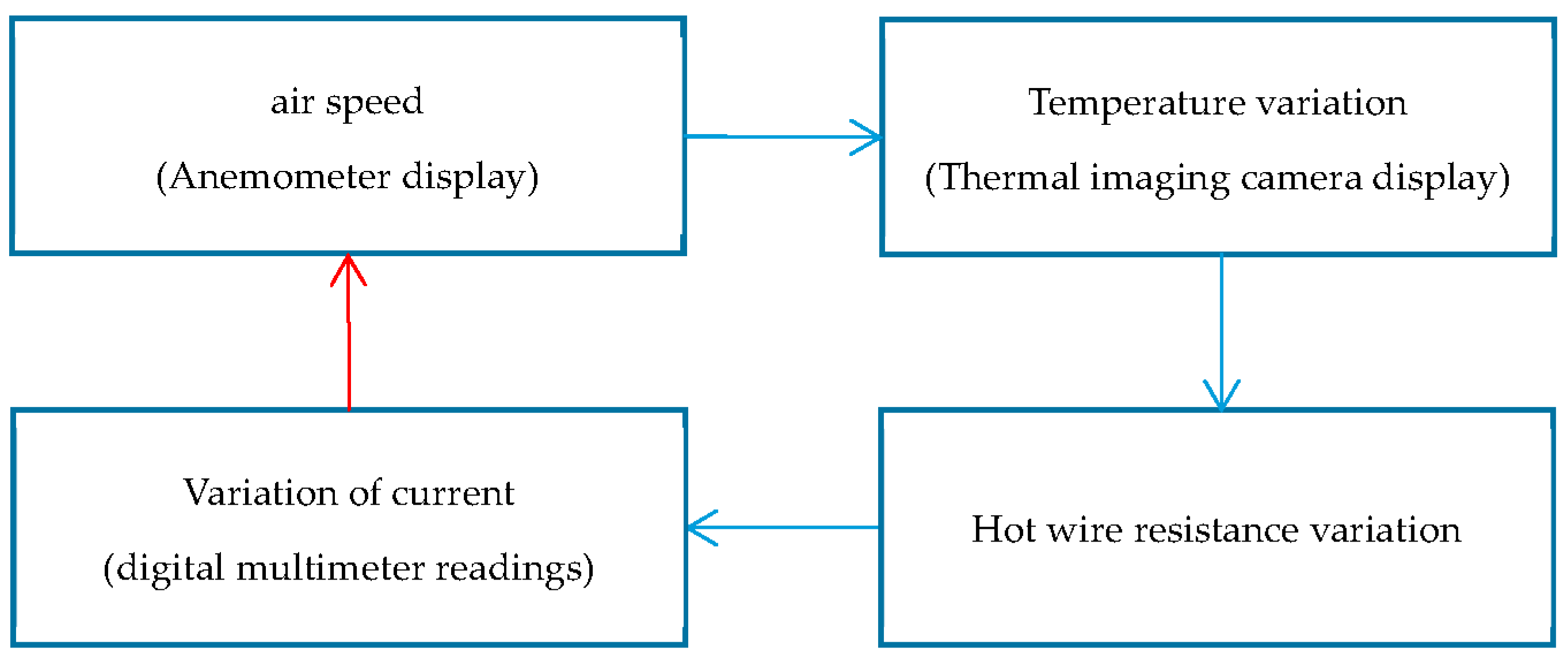
By addressing each module comprehensively, the hot-wire anemometer device not only demonstrates its capabilities in airspeed measurement but also showcases a holistic approach to scientific instrumentation. This comprehensive design bridges theoretical principles with practical applications, offering a valuable tool for both educational and research purposes. Through a synthesis of controlled environmental conditions, comparative measurements, precise temperature tracking, and accurate circuitry, the device stands as a testament to the synergy between engineering ingenuity and scientific understanding. The detailed design ideas are as follows
Figure 1.
The hot wire is connected in parallel with a resistor box, a digital multimeter and an adjustable voltage source are connected in series with the resistor box branch, and then a current source is used to supply current to the whole circuit. The current in the resistor box is measured by the micro-ampere of the digital multimeter, and the change in resistance of the hot wire is obtained. The circuit design is shown in
Figure 2. The system of equations (14) can be obtained from the relationship between the voltages at the ends of the two branches and the current in the circuit.
The digital multimeter's microamp setting reads:
is the current of the current source; ' is the current of the digital multimeter; is the current flowing through the hot wire; r is the resistance of the hot wire; R is the resistance value of the resistance box; is the internal resistance of the digital multimeter; U is the voltage of the voltage source.
Adjust the voltage source so that when there is no wind the digital multimeter microamp gear indicates 0. Then there is
. Assume that when there is a wind field, the electric heating wire resistance changes to Δ
r, the digital multimeter microamp gear indicates the following:
Therefore, the variation of the resistance of the hot wire can be obtained as:
By analyzing Equation (16), it can be found that the value of the resistance R in this circuit has a great influence on the measurement sensitivity of the circuit. When R is small, the change in resistance caused by a unit change in current is smaller and more sensitive, but it causes a larger measurement uncertainty. When R is larger, the circuit measurement uncertainty is smaller, but its sensitivity is reduced. Therefore, the uncertainty needs to be analyzed to get the appropriate value of R. The relative uncertainty of equation (17) is found as follows.
The uncertainties of the relevant instruments are known from the sensitivity of the instruments as follows:
After bringing them into equation (18), we get:
The sensitivity of hot wire resistance measurement can be obtained from Equation (17):
Considering that the resolution of the multimeter is 0.1 μA, it is necessary to control ∆I in the range of 0~500 μA. Therefore, the measurement sensitivity is. When the sensitivity and uncertainty are equal, R≈104Ω, the measurement sensitivity of the resistance is obtained as 10-3Ω. When gradually increasing the air speed, there is an extremely obvious change in the current expression. Therefore, it shows that the circuit and the experimental setup can be used to measure the air speed.
3.2. Apparatus and Materials
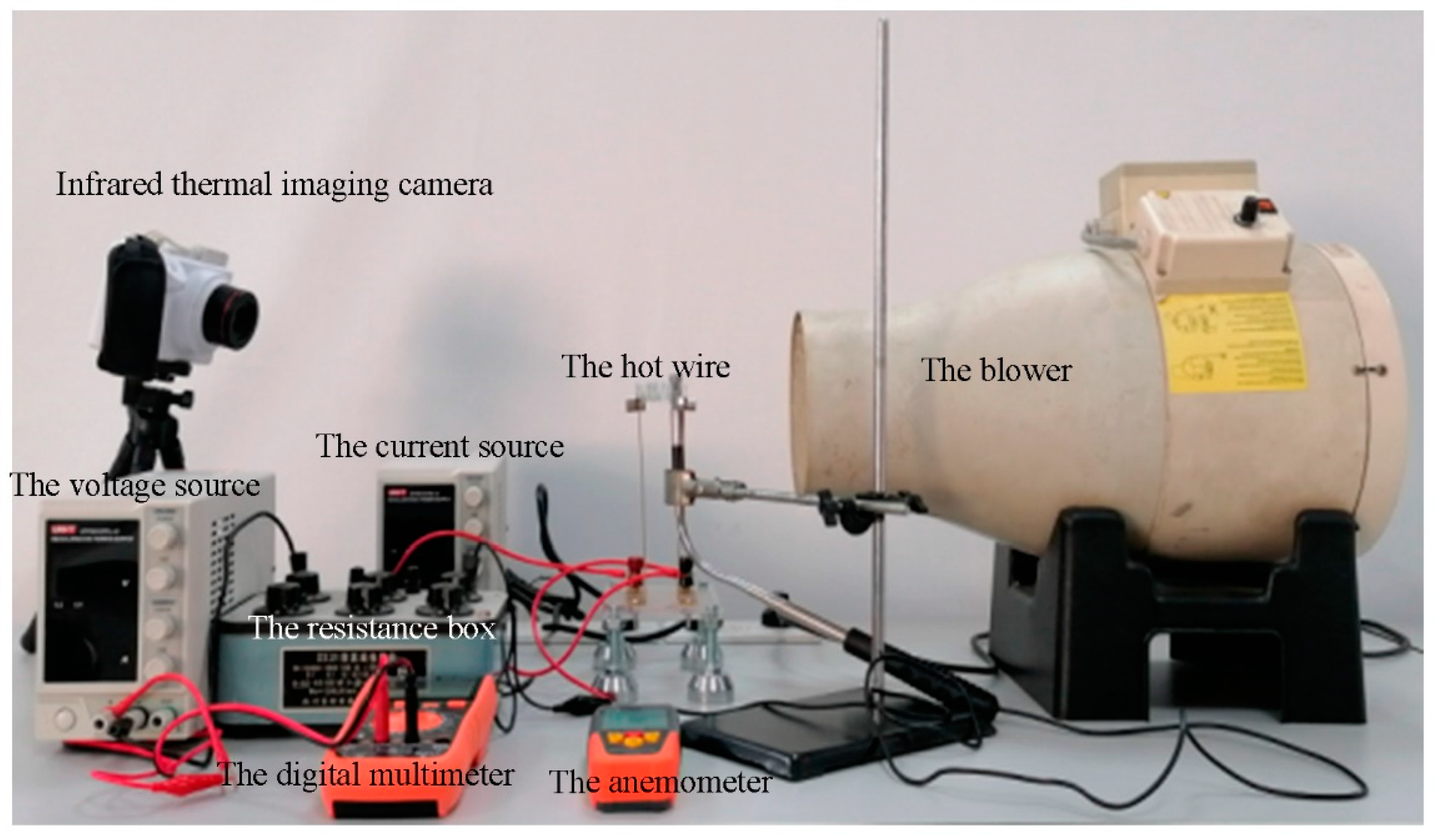
The experimental apparatus is shown in
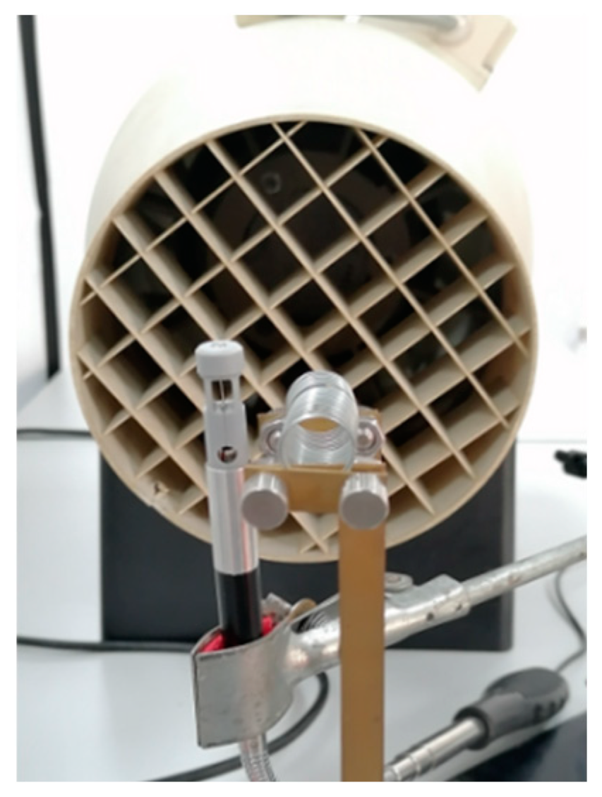
Figure 3. The instruments and materials used are as follows: a blower with adjustable air speed (LEYBOLD DIDACTIC GMBH, 37304) was used as the air speed field environment module. An anemometer (SMART SENSOR, ST866A) measures the actual air speed near the hot wire as the standard air speed measurement module and is placed as shown in
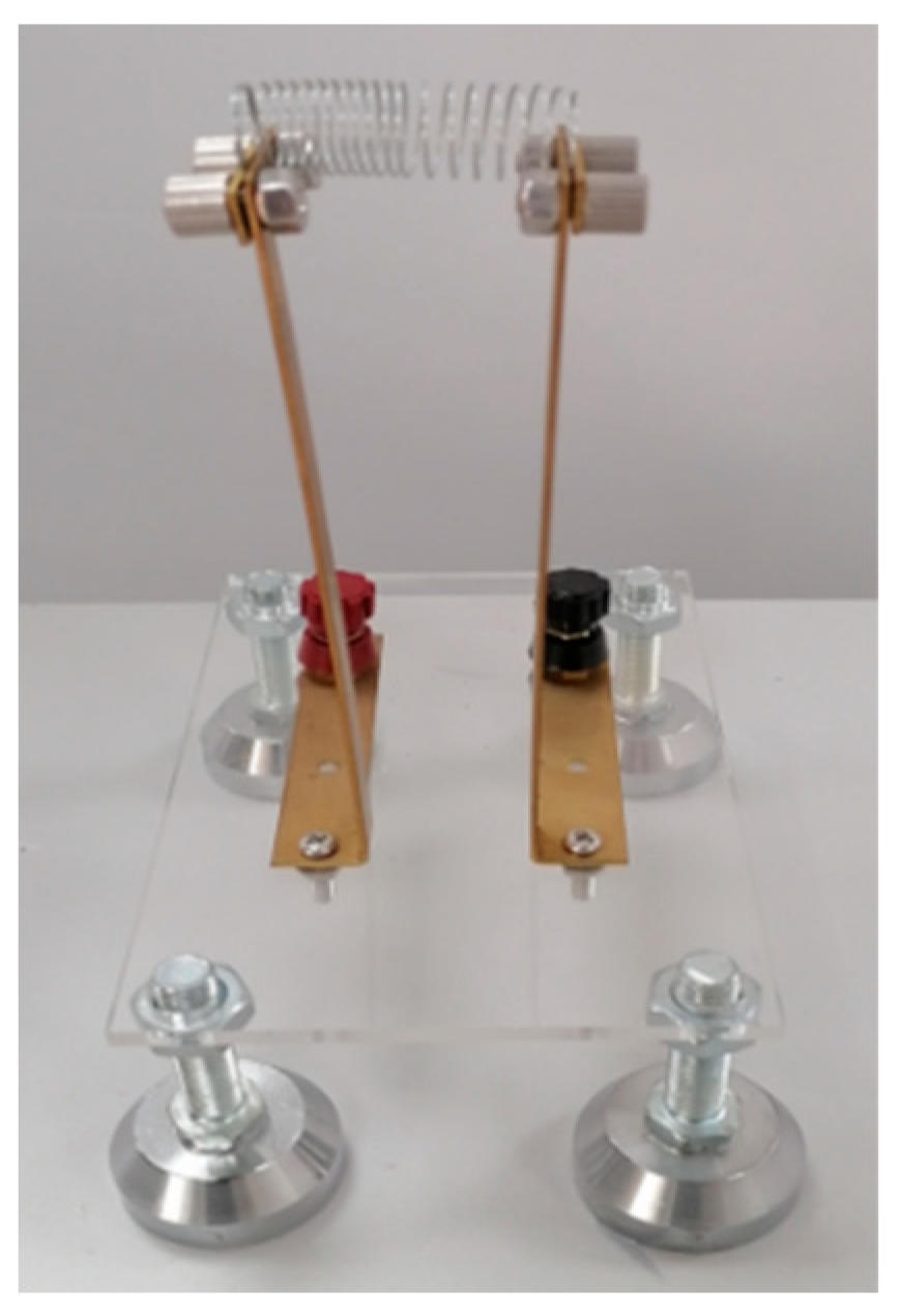
Figure 4. an infrared thermal imaging camera (FOTRIC, 224s) is used to photograph the overall temperature change of the hot wire as the temperature measurement module. The circuit measurement module consists of the following parts: two power supplies (UNI-T,3315TFL-II) as a constant current source to provide a stable current for the whole circuit and a constant voltage source to provide a reverse voltage to make the current adjustable on the branch, a digital multimeter (VICTOR, VC9805A) to measure the weak current on the branch where it is located, a resistor box with adjustable resistance according to the design accuracy The resistor box with adjustable resistance value according to the design accuracy, an iron wire of 0.200mm diameter wound into a spiral-shaped hot wire of 8.00mm diameter and 35.00mm length. The hot wire is fixed on the bracket as shown in
Figure 5. experimental environment temperature: 25.0°C, humidity: 58%-63%.
4. Results and Discussion
4.1. Relationship between Current and Temperature
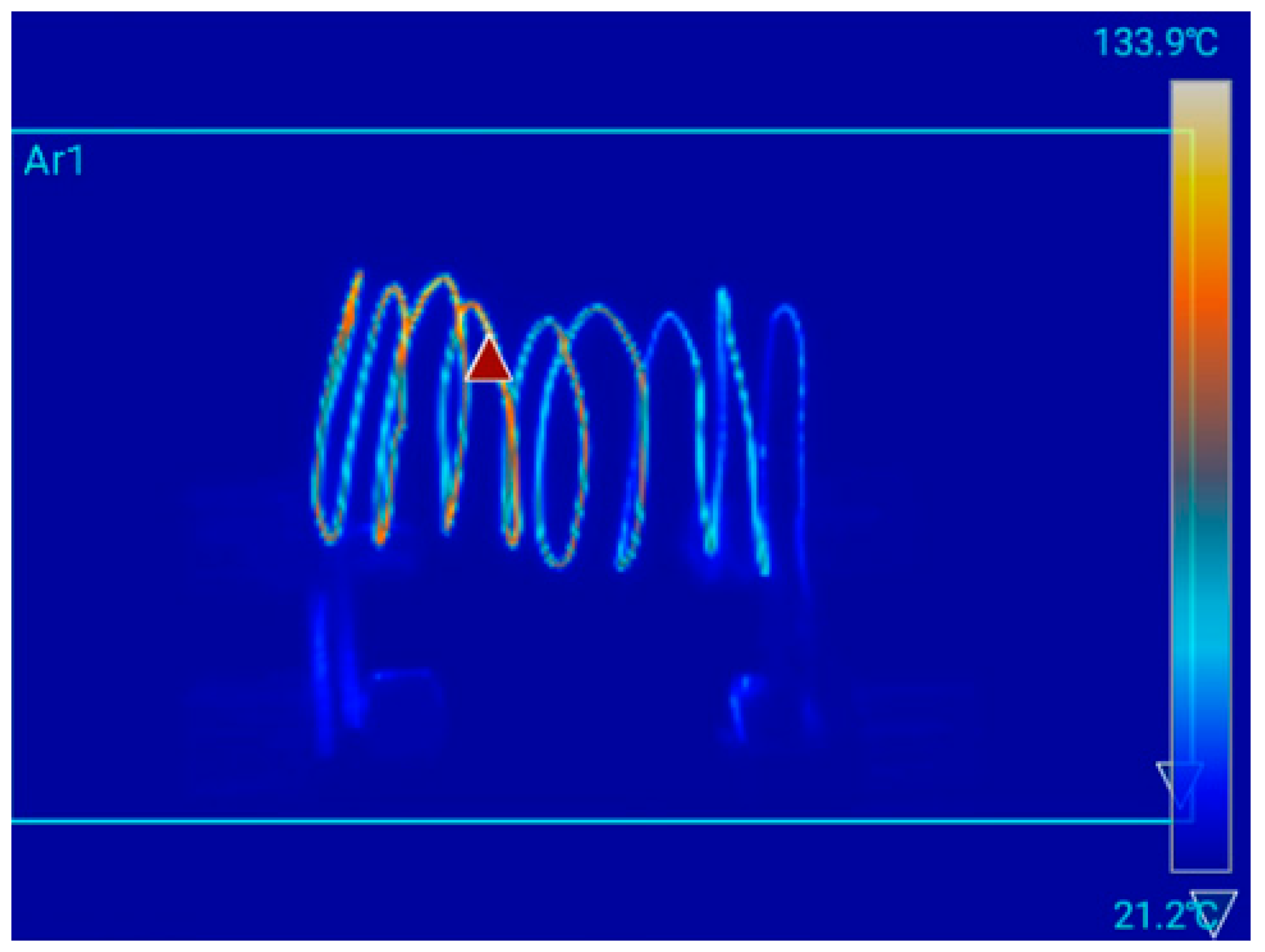
The hot wire was photographed with an infrared thermographic camera and its temperature was recorded. The hot wire temperature recorded by the thermal imaging camera is shown in
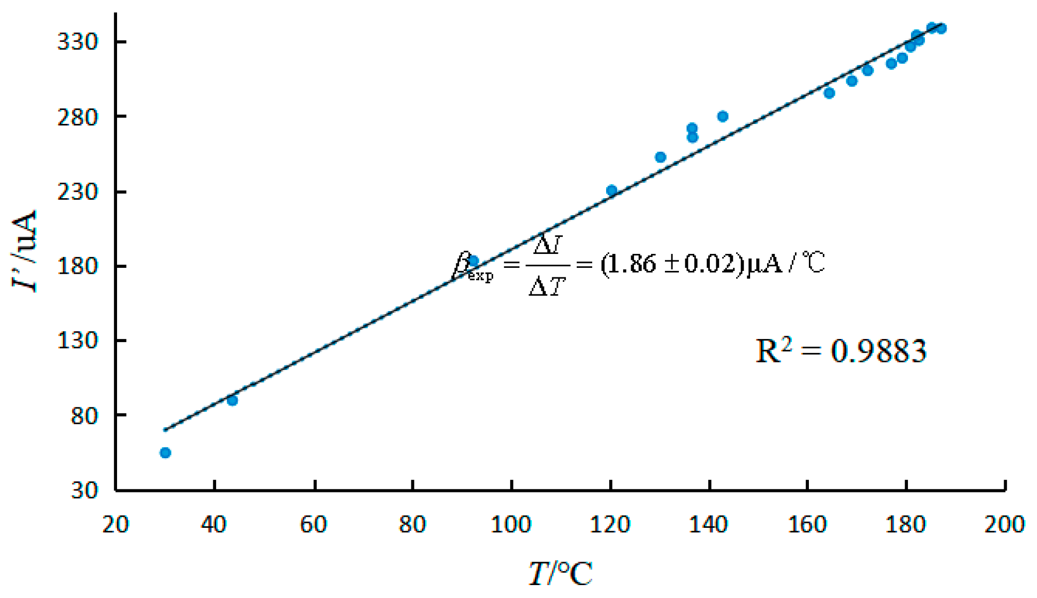
Figure 6. The current was recorded with the current mode of digital multimeter. A graph of temperature versus current for different air speed conditions was made, as shown in
Figure 7. The current was linearly fitted to the temperature to obtain its slope
. The theoretical value
can be obtained from equations (7) and (17), and the two results are more consistent. Because the current and temperature satisfy the linear relationship and the theoretical and experimental values agree within the error range, it indicates that the current can be used to characterize the temperature and further analyze the relationship between air speed and temperature experimentally.
4.2. Relationship between the Air Speed and Hot Wire Temperature
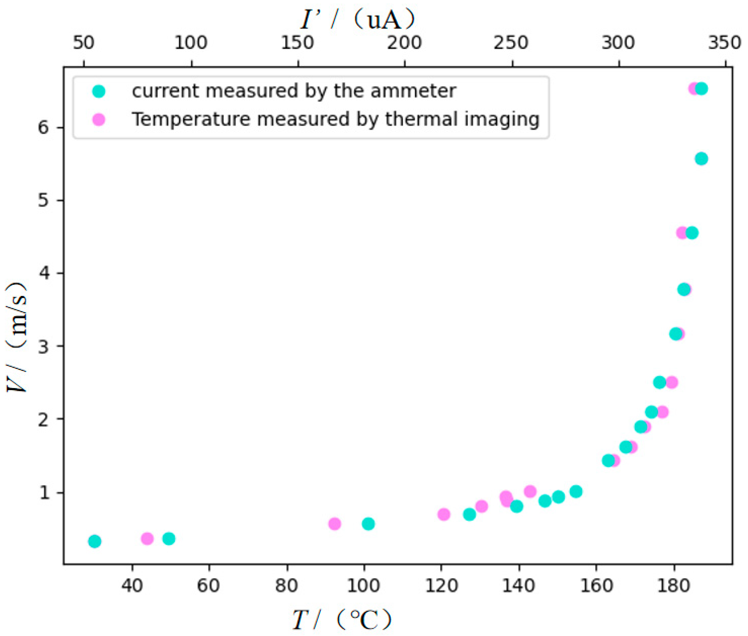
The air speed at the hot wire was measured with an anemometer, the temperature of the hot wire was recorded with a thermal imaging camera, and the current flowing through the constant value resistor box was recorded with a digital multimeter in the microamp class. The current and temperature data measured at different air speeds are plotted in
Figure 8.
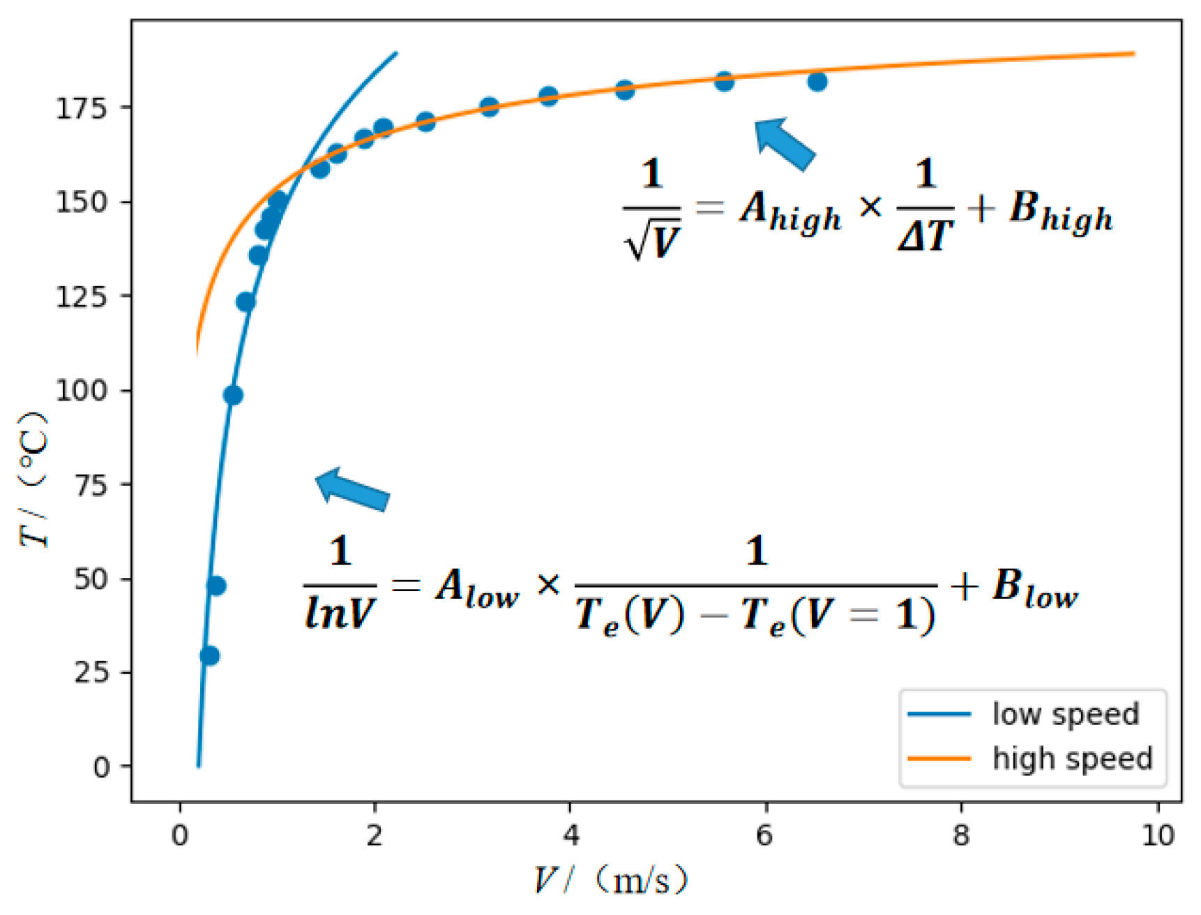
According to the equations (12) and (13) the digital multimeter microamp gear indication and the thermal wire temperature taken by the infrared camera were fitted in two different intervals of low and high air speed, as shown in
Figure 9. The correlation coefficients and expressions can be obtained as follows.
High air speed:
Low air speed:
From the correlation coefficient R2 it can be seen that the data fitting results are in general agreement with the theoretical formula. Therefore, the hot wire anemometer can be designed for different air speed intervals according to this formula.
4.3. Anemometer Sensitivity Analysis
From the previous analysis of the sensitivity of resistance measurement, it is clear that the minimum division of temperature is:
When the air speed is in the range of 0~1.00m/s, the measurement sensitivity is
When the air speed is greater than 1.00m/s:
The relationship between air speed measurement sensitivity and air speed range can be obtained by equation(21). The simple anemometer has different sensitivity in different air speed intervals, and the higher the air speed the lower the sensitivity. According to the worst sensitivity in the interval can set three different measurement sensitivity in the air speed interval. The results are shown in
Table 1 below.
5. Conclusion
The paper calculated the relationship between hot wire temperature and air speed based on the theory of thermal equilibrium, constructed a variable air speed field, produced a homemade hot wire, designed a measurement circuit, and assembled it into a air speed meter. The relationship between current and temperature in the microampere meter under different air speeds was explored using a standard anemometer and an infrared thermal imager. Based on the resulting data, the relationship between air speed and current in different ranges was obtained and agreed well with theoretical predictions. The measurement sensitivity of the designed air speed meter in different ranges was calculated based on the smallest scale of the selected instruments and the uncertainty of the theoretical formula. The experimental results show good agreement with the theoretical predictions.
Based on the results of our experiments and analysis, we conclude that the air speed meter developed in this study is an effective tool for measuring air speed. The device has a high measurement sensitivity and can obtain reliable data on air speeds in different ranges. Additionally, our study confirmed the linear relationship between temperature and current in the microampere meter, demonstrating the potential for using electric current to accurately measure temperature in similar experiments.
Funding
Experimental Technology Research Project of Zhejiang University in 2022 (SYBJS202205)
Conflicts of Interest
On behalf of all authors, the corresponding author states that there is no conflict of interest.
References
- Ligza, P. Method of testing fast-changing and pulsating flows by means of a hot-wire anemometer with simultaneous measurement of voltage and current of the sensor. Measurement 2022, 187, 110291. [Google Scholar] [CrossRef]
- Ligza, P.; Jamróz, P.A. Hot-wire anemometer with automatically adjusted dynamic properties for wind energy spectrum analysis. Energies 2022, 15. [Google Scholar] [CrossRef]
- Gucyetmez, M.; Keser, S.; Hayber, S.E. Air speed measurement with a low-cost polymer optical fiber anemometer based on fresnel reflection. Sensors and Actuators, A. Physical 2022, 339. [Google Scholar]
- Canut, G.; Couvreux, F.; Lothon, M.; Legain, D.; Piguet, B.; Lampert, A.; et al. Turbulence fluxes and variances measured with a sonic anemometer mounted on a tethered balloon. Atmospheric Measurement Techniques 2016, 9, 4375–4386. [Google Scholar] [CrossRef]
- Liu, G.; Hou, W.; Qiao, W.; Han, M. Fast-response fiber-optic anemometer with temperature self-compensation. Optics Express 2015, 23, 13562. [Google Scholar] [CrossRef] [PubMed]
- Johnson, D.A.; Rose, W.C. Laser velocimeter and hot-wire anemometer comparison in a supersonic boundary layer. Aiaa Journal 2015, 13, 512–515. [Google Scholar] [CrossRef]
- Thielicke, W.; WHübert UMüller Eggert, M.; Wilhelm, P. Towards accurate and practical drone-based wind measurements with an ultrasonic anemometer. Atmospheric Measurement Techniques(2) 2021. [CrossRef]
- Adamec, R.J.; Thiel, D.V. Self heated thermo-resistive element hot wire anemometer. IEEE Sensors Journal 2010, 10, 847–848. [Google Scholar] [CrossRef]
- Kovasznay, L. The hot-wire anemometer in supersonic flow. Journal of the Aeronautical Sciences 2015, 17, 565–572. [Google Scholar] [CrossRef]
- Fischer, A. Hot wire anemometer turbulence measurements in the wind tunnel of lm wind power. technical univ.of denmark.dtu wind energy roskilde. 2012.
- Doolan, C.; Coton, F.; Galbraith, R. Measurement of three-dimensional vortices using a hot wire anemometer. Fluid Dynamics Conference. 2013.
- Zhang, J.; Gao, G.; Huang, S.; Liu, T. Effect on measurements of anemometers due to a passing high-speed train. Wind & Structures An International Journal 2015, 20, 549–564. [Google Scholar]
- Durì, D.; Baudet, C.; Moro, J.P.; et al. Hot-wire anemometry for superfluid turbulent coflows 2015, 86, 167–231.
- Mikheev, N.I.; Sakhovsky, A.V.; Khairnasov, K.R.; Kratirov, D.V. Heat-transfer regularities of the anemometric wire. Thermophysics and Aeromechanics, 2010, 17, 173–180. [Google Scholar] [CrossRef]
- Kielbasa, J. The hot-wire anemometer. Archives of Mining Sciences = Archiwum Górnictwa, 2014, 59, 467–475. [Google Scholar] [CrossRef]
- Ligeza, P. Modeling of complex hot-wire measuring system. Optoelectronic and Electronic Sensor IV 2001, 4516, 131–138. [Google Scholar]
- Coffaro, J.; Richardson, M.; Bernath, R.; Crabbs, R. Sonic anemometer data processing for comparison to optical turbulence theory and simulation. Journal of the Optical Society of America, A. Optics, image science, and vision(4) 2022, 39. [Google Scholar] [CrossRef] [PubMed]
- King, L.V. On the Convection of Heat from Small Cylinders in a Stream of Fluid : Determination of the Convection Constants of Small Platinum Wires with Applications to Hot-Wire Anemometry. Philos. Trans. Roy. Soc. London, Ser. A 1914, 214, 373–432. [Google Scholar]
- Lundstrm, H. Investigation of heat transfer from thin wires in air and a new method for temperature correction of hot-wire anemometers. Experimental Thermal and Fluid Science (EXP THERM FLUID SCI) 2021, 110403. [Google Scholar] [CrossRef]
- EÖÖÇY GündoǧduSimple methods for low speed calibration of hot-wire anemometers. Flow Measurement and Instrumentation 2010.
- Kaplan, H. Practical applications of infrared thermal sensing and imaging equipment. SPIE Press, 2007.
|
Disclaimer/Publisher’s Note: The statements, opinions and data contained in all publications are solely those of the individual author(s) and contributor(s) and not of MDPI and/or the editor(s). MDPI and/or the editor(s) disclaim responsibility for any injury to people or property resulting from any ideas, methods, instructions or products referred to in the content. |
© 2023 by the authors. Licensee MDPI, Basel, Switzerland. This article is an open access article distributed under the terms and conditions of the Creative Commons Attribution (CC BY) license (https://creativecommons.org/licenses/by/4.0/).
