Submitted:
08 August 2023
Posted:
09 August 2023
You are already at the latest version
Abstract
Keywords:
1. Introduction
2. Materials and Methods
2.1. Materials
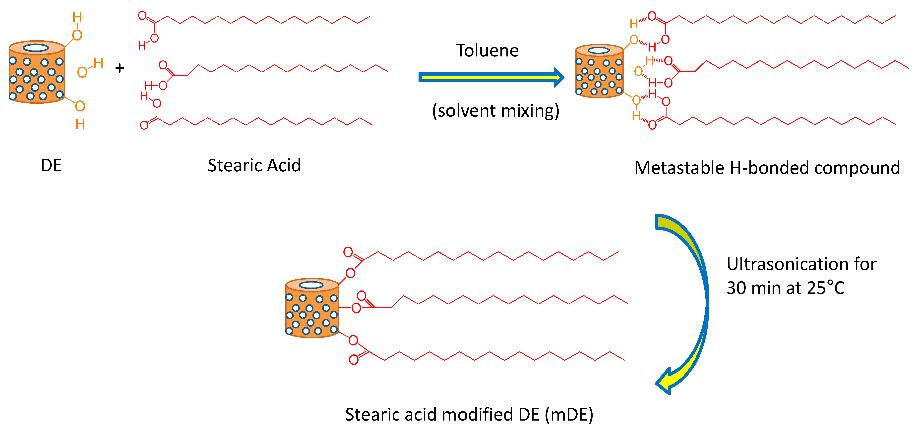
2.2. Stearic acid treatment of diatomaceous earth
2.3. Characterizations of fillers
2.4. Fabrication of rubber composites.
2.5. Mechanical properties
2.6. Swelling properties
2.7. Electrical and electromechanical sensing properties
3. Results and discussion
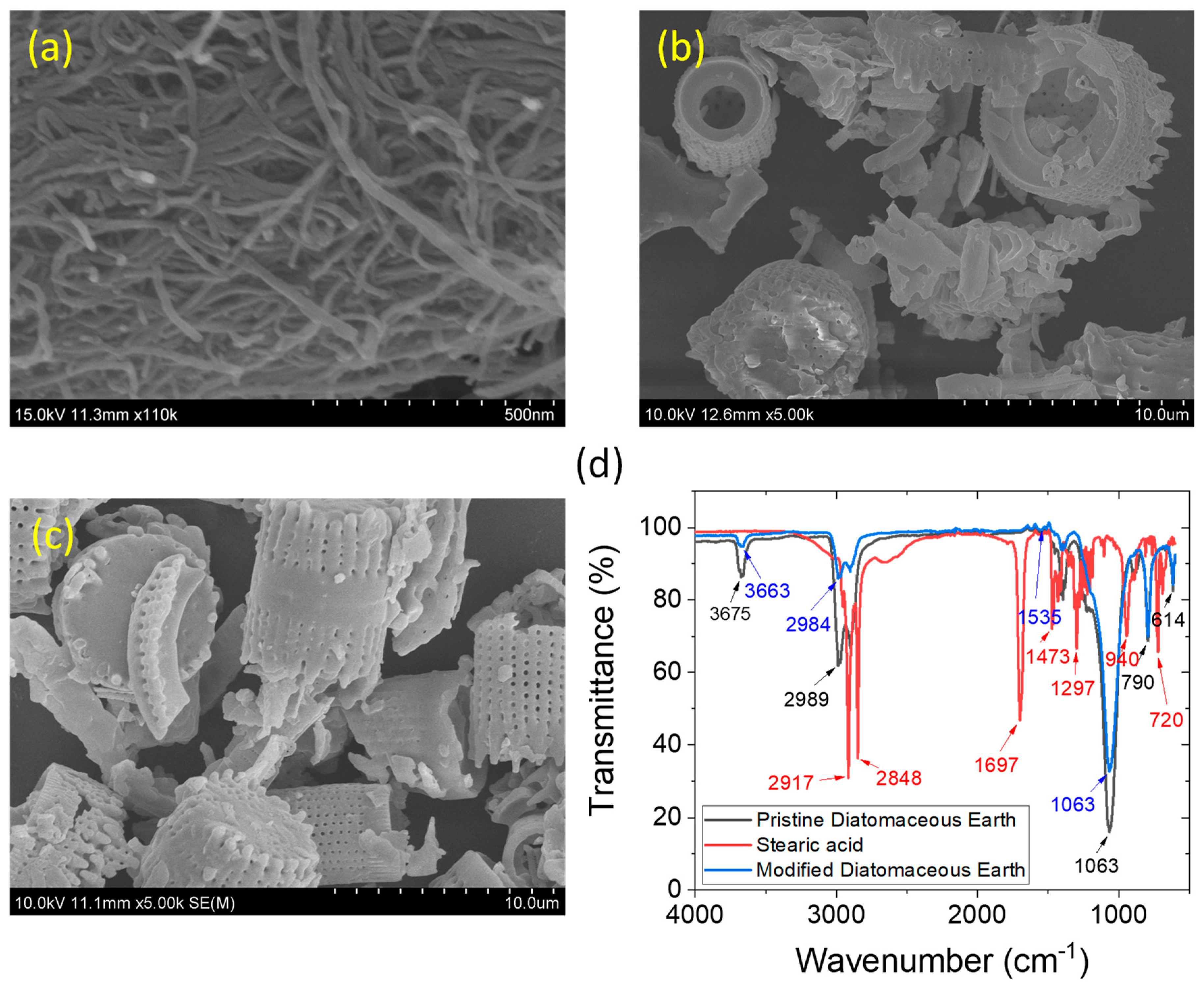
3.1. Characteristics of the filler materials
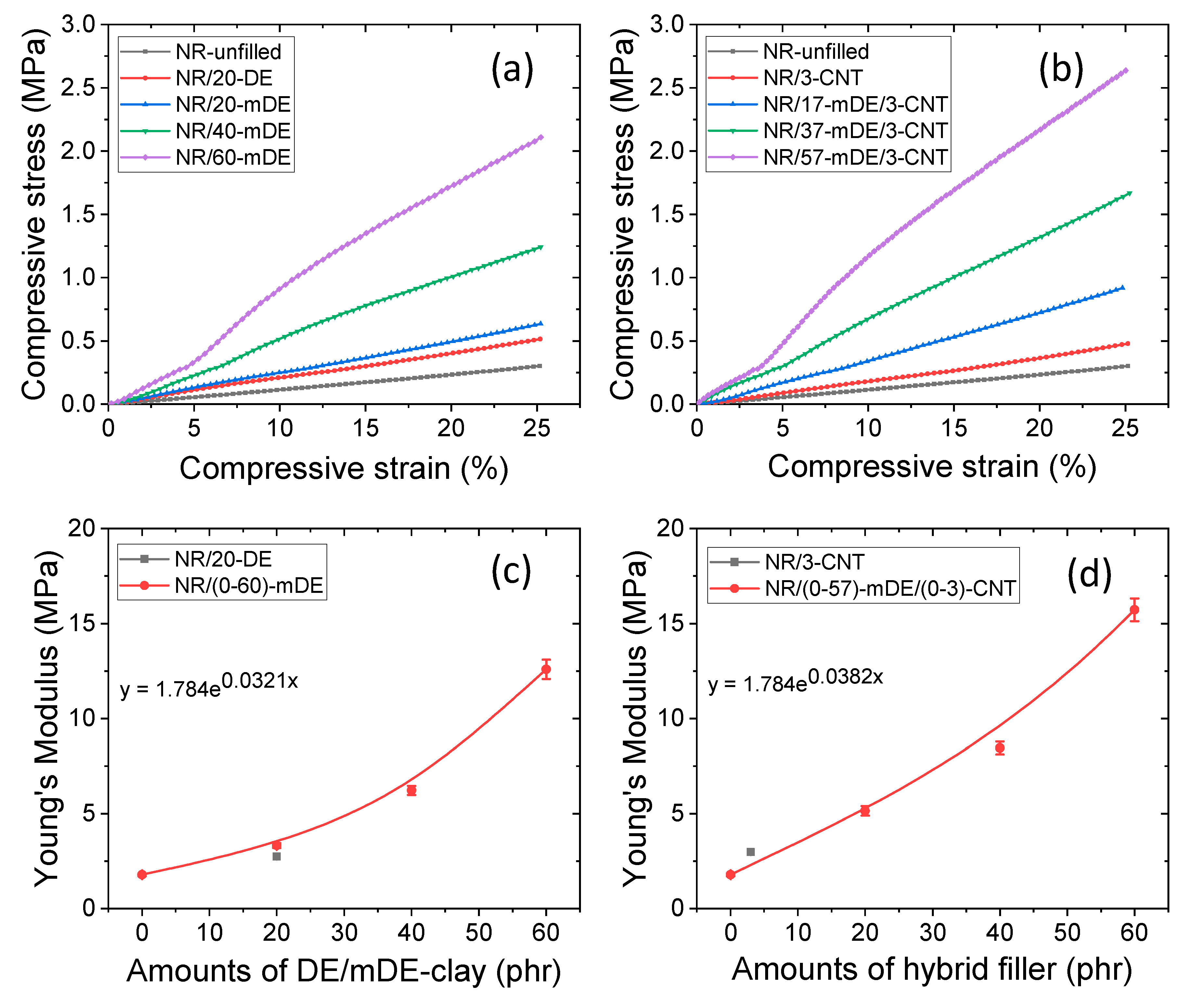
3.2. Mechanical and physical properties of the rubber composites
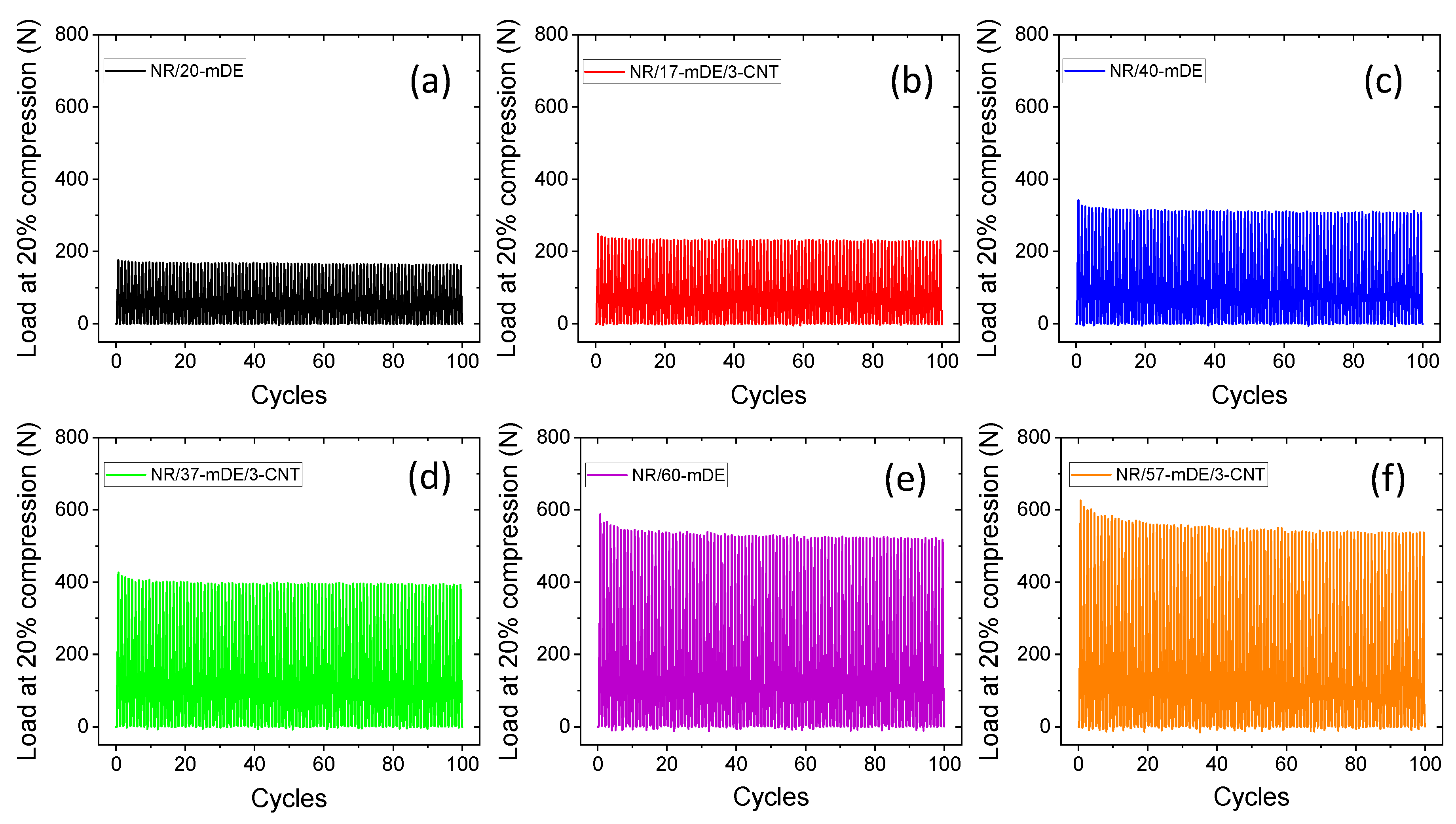
3.3. Electrical and energy harvesting performances of the rubber composites
4. Conclusions
Author Contributions
Funding
Institutional Review Board Statement
Data Availability Statement
Acknowledgments
Conflicts of Interest
References
- Progress in Rubber Nanocomposites; Thomas, S., Maria, H.J., Eds.; Woodhead Publishing: Cambridge, UK, 2017. [Google Scholar]
- Shahapurkar, K.; Gelaw, M.; Tirth, V.; Soudagar, M.E.M.; Shahapurkar, P.; Mujtaba, M.A.; MC, K.; Ahmed, G.M.S. Comprehensive Review on Polymer Composites as Electromagnetic Interference Shielding Materials. Polymers and Polymer Composites 2022, 30, 09673911221102127. [Google Scholar] [CrossRef]
- Zhan, Y.; Oliviero, M.; Wang, J.; Sorrentino, A.; Buonocore, G.G.; Sorrentino, L.; Lavorgna, M.; Xia, H.; Iannace, S. Enhancing the EMI Shielding of Natural Rubber-Based Supercritical CO2 Foams by Exploiting Their Porous Morphology and CNT Segregated Networks. Nanoscale 2019, 11, 1011–1020. [Google Scholar] [CrossRef]
- Zhang, X.; Fan, C.; Ma, Y.; Zhao, H.; Sui, J.; Liu, J.; Sun, C. Elastic Composites Fabricating for Electromagnetic Interference Shielding Based on MWCNTs and Fe3O4 Unique Distribution in Immiscible NR/NBR Blends. Polymer Engineering & Science 2022, 62, 2019–2030. [Google Scholar]
- Kim, H.J.; Thukral, A.; Yu, C. Highly Sensitive and Very Stretchable Strain Sensor Based on a Rubbery Semiconductor. ACS Applied Materials & Interfaces 2018, 10, 5000–5006. [Google Scholar]
- Souri, H.; Banerjee, H.; Jusufi, A.; Radacsi, N.; Stokes, A.A.; Park, I.; Sitti, M.; Amjadi, M. Wearable and Stretchable Strain Sensors: Materials, Sensing Mechanisms, and Applications. Advanced Intelligent Systems 2020, 2, 2000039. [Google Scholar] [CrossRef]
- Alam, M.N.; Kumar, V.; Lee, D.J.; Choi, J. Synergistically Toughened Silicone Rubber Nanocomposites Using Carbon Nanotubes and Molybdenum Disulfide for Stretchable Strain Sensors. Composites Part B: Engineering 2023, 259, 110759. [Google Scholar] [CrossRef]
- Zhang, H.; Yao, L.; Quan, L.; Zheng, X. Theories for Triboelectric Nanogenerators: A Comprehensive Review. Nanotechnology Reviews 2020, 9, 610–625. [Google Scholar] [CrossRef]
- Yi, F.; Lin, L.; Niu, S.; Yang, P.K.; Wang, Z.; Chen, J.; Zhou, Y.; Zi, Y.; Wang, J.; Liao, Q.; Zhang, Y. Stretchable Rubber-Based Triboelectric Nanogenerator and Its Application as Self-Powered Body Motion Sensors. Advanced Functional Materials 2015, 25, 3688–3696. [Google Scholar] [CrossRef]
- Li, Y.; Li, J.; Li, W.; Du, H. A State-of-the-Art Review on Magnetorheological Elastomer Devices. Smart Materials and Structures 2014, 23, 123001. [Google Scholar] [CrossRef]
- Alam, M.N.; Kumar, V.; Jo, C.R.; Ryu, S.R.; Lee, D.J.; Park, S.S. Mechanical and Magneto-Mechanical Properties of Styrene-Butadiene-Rubber-Based Magnetorheological Elastomers Conferred by Novel Filler-Polymer Interactions. Composites Science and Technology 2022, 229, 109669. [Google Scholar] [CrossRef]
- Liu, Y.; Pharr, M.; Salvatore, G.A. Lab-on-Skin: A Review of Flexible and Stretchable Electronics for Wearable Health Monitoring. ACS Nano 2017, 11, 9614–9635. [Google Scholar] [CrossRef]
- Alam, M.N.; Kumar, V.; Debnath, S.C.; Jeong, T.; Park, S.S. Naturally Abundant Silica-Kaolinite Mixed Minerals as an Outstanding Reinforcing Filler for the Advancement of Natural Rubber Composites. Journal of Polymer Research 2023, 30, 59. [Google Scholar] [CrossRef]
- Ma, P.C.; Siddiqui, N.A.; Marom, G.; Kim, J.K. Dispersion and Functionalization of Carbon Nanotubes for Polymer-Based Nano-composites: A Review. Composites Part A: Applied Science and Manufacturing 2010, 41, 1345–1367. [Google Scholar] [CrossRef]
- Mensah, B.; Kim, H.G.; Lee, J.H.; Arepalli, S.; Nah, C. Carbon Nanotube-Reinforced Elastomeric Nanocomposites: A Review. International Journal of Smart and Nano Materials 2015, 6, 211–238. [Google Scholar] [CrossRef]
- Geetha, S.; Satheesh Kumar, K.K.; Rao, C.R.; Vijayan, M.; Trivedi, D.C. EMI Shielding: Methods and Materials-A Review. Journal of Applied Polymer Science 2009, 112, 2073–2086. [Google Scholar] [CrossRef]
- Park, M.; Park, J.; Jeong, U. Design of Conductive Composite Elastomers for Stretchable Electronics. Nano Today 2014, 9, 244–260. [Google Scholar] [CrossRef]
- Zhao, Y.; Yin, L.J.; Zhong, S.L.; Zha, J.W.; Dang, Z.M. Review of Dielectric Elastomers for Actuators, Generators, and Sensors. IET Nanodielectrics 2020, 3, 99–106. [Google Scholar] [CrossRef]
- Park, K.I.; Jeong, C.K.; Kim, N.K.; Lee, K.J. Stretchable Piezoelectric Nanocomposite Generator. Nano Convergence 2016, 3, 12. [Google Scholar] [CrossRef] [PubMed]
- Koh, S.J.A.; Keplinger, C.; Li, T.; Bauer, S.; Suo, Z. Dielectric Elastomer Generators: How Much Energy Can Be Converted? IEEE/ASME Transactions on Mechatronics 2010, 16, 33–41. [Google Scholar] [CrossRef]
- Chiba, S.; Waki, M.; Jiang, C.; Takeshita, M.; Uejima, M.; Arakawa, K.; Ohyama, K. The Possibility of a High-Efficiency Wave Power Generation System Using Dielectric Elastomers. Energies 2021, 14, 3414. [Google Scholar] [CrossRef]
- Di, K.; Bao, K.; Chen, H.; Xie, X.; Tan, J.; Shao, Y.; Li, Y.; Xia, W.; Xu, Z.; E, S. Dielectric Elastomer Generator for Electromechanical Energy Conversion: A Mini Review. Sustainability 2021, 13, 9881. [Google Scholar] [CrossRef]
- Uyor, U.O.; Popoola, A.P.I.; Popoola, O.M.; Aigbodion, V.S. Thermal, Mechanical, and Dielectric Properties of Functionalized Sandwich BN-BaTiO3-BN/Polypropylene Nanocomposites. Journal of Alloys and Compounds 2022, 894, 162405. [Google Scholar] [CrossRef]
- Zeng, Y.; Xiong, C.; Li, W.; Rao, S.; Du, G.; Fan, Z.; Chen, N. Significantly Improved Dielectric and Mechanical Performance of Ti3C2Tx MXene/Silicone Rubber Nanocomposites. Journal of Alloys and Compounds 2022, 905, 164172. [Google Scholar] [CrossRef]
- Salaeh, S.; Muensit, N.; Bomlai, P.; Nakason, C. Ceramic/Natural Rubber Composites: Influence Types of Rubber and Ceramic Materials on Curing, Mechanical, Morphological, and Dielectric Properties. Journal of Materials Science 2011, 46, 1723–1731. [Google Scholar] [CrossRef]
- Chang, B.P.; Gupta, A.; Muthuraj, R.; Mekonnen, T.H. Bioresourced Fillers for Rubber Composite Sustainability: Current Development and Future Opportunities. Green Chemistry 2021, 23, 5337–5378. [Google Scholar] [CrossRef]
- Bhagavatheswaran, E.S.; Das, A.; Rastin, H.; Saeidi, H.; Jafari, S.H.; Vahabi, H.; Najafi, F.; Khonakdar, H.A.; Formela, K.; Jouyandeh, M.; Zarrintaj, P. The Taste of Waste: The Edge of Eggshell over Calcium Carbonate in Acrylonitrile Butadiene Rubber. Journal of Polymer and the Environment 2019, 27, 2478–2489. [Google Scholar] [CrossRef]
- Ten Brinke, J.W.; Debnath, S.C.; Reuvekamp, L.A.; Noordermeer, J.W. Mechanistic Aspects of the Role of Coupling Agents in Silica-Rubber Composites. Composites Science and Technology 2003, 63, 1165–1174. [Google Scholar] [CrossRef]
- Mora-Barrantes, I.; Rodríguez, A.; Ibarra, L.; González, L.; Valentín, J.L. Overcoming the Disadvantages of Fumed Silica as Filler in Elastomer Composites. Journal of Materials Chemistry 2011, 21, 7381–7392. [Google Scholar] [CrossRef]
- Sarkawi, S.S.; Kaewsakul, W.; Sahakaro, K.; Dierkes, W.K.; Noordermeer, J.W. A Review on Reinforcement of Natural Rubber by Silica Fillers for Use in Low-Rolling Resistance Tires. Journal of Rubber Research 2015, 18, 203–233. [Google Scholar]
- Beidaghy Dizaji, H.; Zeng, T.; Hartmann, I.; Enke, D.; Schliermann, T.; Lenz, V.; Bidabadi, M. Generation of High-Quality Biogenic Silica by Combustion of Rice Husk and Rice Straw Combined with Pre-and Post-Treatment Strategies-A Review. Applied Sciences 2019, 9, 1083. [Google Scholar] [CrossRef]
- Choophun, N.; Chaiammart, N.; Sukthavon, K.; Veranitisagul, C.; Laobuthee, A.; Watthanaphanit, A.; Panomsuwan, G. Natural Rubber Composites Reinforced with Green Silica from Rice Husk: Effect of Filler Loading on Mechanical Properties. Journal of Composites Science 2022, 6, 369. [Google Scholar] [CrossRef]
- Sardo, A.; Orefice, I.; Balzano, S.; Barra, L.; Romano, G. Mini-Review: Potential of Diatom-Derived Silica for Biomedical Applications. Applied Sciences 2021, 11, 4533. [Google Scholar] [CrossRef]
- Reka, A.A.; Smirnov, P.V.; Belousov, P.; Durmishi, B.; Abbdesettar, L.; Aggrey, P.; Kabra Malpani, S.; Idrizi, H. Diatomaceous Earth: A Literature Review. Journal of Natural Sciences and Mathematics 2022, 7, 256–268. [Google Scholar]
- Scotti, R.; Conzatti, L.; D'Arienzo, M.; Di Credico, B.; Giannini, L.; Hanel, T.; Stagnaro, P.; Susanna, A.; Tadiello, L.; Morazzoni, F. Shape Controlled Spherical (0D) and Rod-like (1D) Silica Nanoparticles in Silica/Styrene Butadiene Rubber Nanocomposites: Role of the Particle Morphology on the Filler Reinforcing Effect. Polymers 2014, 55, 1497–1506. [Google Scholar] [CrossRef]
- Fröhlich, J.; Niedermeier, W.; Luginsland, H.D. The Effect of Filler-Filler and Filler-Elastomer Interaction on Rubber Reinforcement. Composites Part A: Applied Science and Manufacturing 2005, 36, 449–460. [Google Scholar] [CrossRef]
- Olewnik-Kruszkowska, E.; Brzozowska, W.; Adamczyk, A.; Gierszewska, M.; Wojtczak, I.; Sprynskyy, M. Effect of Diatomaceous Biosilica and Talc on the Properties of Dielectric Elastomer-Based Composites. Energies 2020, 13, 5828. [Google Scholar] [CrossRef]
- Kucuk, F.; Sismanoglu, S.; Kanbur, Y.; Tayfun, U. Optimization of Mechanical, Thermo-Mechanical, Melt-Flow, and Thermal Performance of TPU Green Composites by Diatomaceous Earth Content. Clean Engineering and Technology 2021, 4, 100251. [Google Scholar] [CrossRef]
- Marković, G.; Marinović-Cincović, M.; Jovanović, V.; Samaržija-Jovanović, S.; Budinski-Simendić, J. NR/CSM/Biogenic Silica Rubber Blend Composites. Composites Part B: Engineering 2013, 55, 368–373. [Google Scholar] [CrossRef]
- Porobić, S.J.; Marković, G.; Ristić, I.; Samaržija-Jovanović, S.; Jovanović, V.; Budinski-Simendić, J.; Marinović-Ćinčović, M. Hybrid Materials Based on Rubber Blend Nanocomposites. Polymers and Composites 2019, 40, 3056–3064. [Google Scholar] [CrossRef]
- Kucuk, F.; Sismanoglu, S.; Kanbur, Y.; Tayfun, U. Effect of Silane-Modification of Diatomite on its Composites with Thermoplastic Polyurethane. Materials and Chemistry Physics 2020, 256, 123683. [Google Scholar] [CrossRef]
- Wu, W.L.; Chen, Z. Modified-diatomite Reinforced Rubbers. Materials Letters 2017, 209, 159–162. [Google Scholar] [CrossRef]
- Arias, M.; Van Dijk, P. What is Natural Rubber and Why Are We Searching for New Sources. Frontiers for Young Minds 2019, 7, 100. [Google Scholar] [CrossRef]
- Bokobza, L. Natural Rubber Nanocomposites: A Review. Nanomaterials 2018, 9, 12. [Google Scholar] [CrossRef]
- Sethulekshmi, A.S.; Saritha, A.; Joseph, K. A Comprehensive Review on the Recent Advancements in Natural Rubber Nanocomposites. International Journal of Biological Macromolecules 2022, 194, 819–842. [Google Scholar] [CrossRef]
- Ambegoda, V.T.; Egodage, S.M.; Blum, F.D.; Maddumaarachchi, M. Enhancement of Hydrophobicity of Natural Rubber Latex Films Using Diatomaceous Earth. Journal of Applied Polymer Science 2021, 138, 50047. [Google Scholar] [CrossRef]
- Alam, M.N.; Kumar, V.; Ryu, S.R.; Ko, T.J.; Lee, D.J.; Choi, J. Synergistic Magnetorheological NR-NBR Elastomer Blend with Electrolytic Iron Particles. Rubber Chemistry and Technology 2021, 94, 642–656. [Google Scholar] [CrossRef]
- Alam, M.N.; Choi, J. Highly Reinforced Magneto-Sensitive Natural-Rubber Nanocomposite Using Iron Oxide/Multilayer Graphene as Hybrid Filler. Composites Communications 2022, 32, 101169. [Google Scholar] [CrossRef]
- Flory, P.J.; Rehner Jr, J. Statistical Mechanics of Cross-Linked Polymer Networks I. Rubberlike Elasticity. Journal of Chemical Physics 1943, 11, 512–520. [Google Scholar] [CrossRef]
- Ilia, I.; Stamatakis, M.; Perraki, T. Mineralogy and Technical Properties of Clayey Diatomites from North and Central Greece. Open Geosciences 2009, 1, 393–403. [Google Scholar] [CrossRef]
- Balan, E.; Saitta, A.M.; Mauri, F.; Calas, G. First-Principles Modeling of the Infrared Spectrum of Kaolinite. American Mineralogist 2001, 86, 1321–1330. [Google Scholar] [CrossRef]
- Madejová, J.; Janek, M.; Komadel, P.; Herbert, H.J.; Moog, H.C. FTIR Analyses of Water in MX-80 Bentonite Compacted from High Salinity Salt Solution Systems. Applied Clay Science 2002, 20, 255–271. [Google Scholar] [CrossRef]
- Zeng, Y.X.; Zhong, X.W.; Liu, Z.Q.; Chen, S.; Li, N. Preparation and Enhancement of Thermal Conductivity of Heat Transfer Oil-Based MoS2 Nanofluids. Journal of Nanomaterials 2013, 2013, 270490. [Google Scholar] [CrossRef]
- Li, Z.; Shen, S.Y.; Peng, J.R.; Yang, C.R. Mechanochemical Modification of Wollastonite and Its Application to Polypropylene. Key Engineering Materials 2003, 249, 409–412. [Google Scholar] [CrossRef]
- Sari, A.; Işildak, Ş. Adsorption Properties of Stearic Acid onto Untreated Kaolinite. Bulletin of the Chemical Society of Ethiopia 2006, 20, 259–267. [Google Scholar] [CrossRef]
- Kumar, R.M.; Sharma, S.K.; Kumar, B.M.; Lahiri, D. Effects of Carbon Nanotube Aspect Ratio on Strengthening and Tribological Behavior of Ultra High Molecular Weight Polyethylene Composite. Composites Part A: Applied Science and Manufacturing 2015, 76, 62–72. [Google Scholar] [CrossRef]
- Kucherskii, A.M. Hysteresis Losses in Carbon-Black-Filled Rubbers Under Small and Large Elongations. Polymer Testing 2005, 24, 733–738. [Google Scholar] [CrossRef]
- Alam, M.N.; Kumar, V.; Potiyaraj, P.; Lee, D.J.; Choi, J. Mutual Dispersion of Graphite-Silica Binary Fillers and Its Effects on Curing, Mechanical, and Aging Properties of Natural Rubber Composites. Polymer Bulletin 2022, 79, 2707–2724. [Google Scholar] [CrossRef]
- Ivanoska-Dacikj, A.; Bogoeva-Gaceva, G.; Vali?, S.; Wießner, S.; Heinrich, G. Benefits of Hybrid Nano-Filler Networking Between Organically Modified Montmorillonite and Carbon Nanotubes in Natural Rubber: Experiments and Theoretical Interpretations. Applied Clay Science 2017, 136, 192–198. [Google Scholar] [CrossRef]
- Mazzotta, M.G.; Putnam, A.A.; North, M.A.; Wilker, J.J. Weak Bonds in a Biomimetic Adhesive Enhance Toughness and Performance. Journal of the American Chemical Society 2020, 142, 4762–4768. [Google Scholar] [CrossRef]
- Yuan, J.K.; Li, W.L.; Yao, S.H.; Lin, Y.Q.; Sylvestre, A.; Bai, J. High Dielectric Permittivity and Low Percolation Threshold in Polymer Composites Based on SiC-Carbon Nanotubes Micro/Nano Hybrid. Applied Physics Letters 2011, 98, 032901. [Google Scholar] [CrossRef]
- Zeng, Y.; Xiong, C.; Li, W.; Rao, S.; Du, G.; Fan, Z.; Chen, N. Significantly Improved Dielectric and Mechanical Performance of Ti3C2Tx MXene/Silicone Rubber Nanocomposites. Journal of Alloys and Compounds 2022, 905, 164172. [Google Scholar] [CrossRef]
- Zang, Y.; Zhang, F.; Di, C.A.; Zhu, D. Advances of Flexible Pressure Sensors toward Artificial Intelligence and Health Care Applications. Materials Horizons 2015, 2, 140–156. [Google Scholar] [CrossRef]
- Alam, M.N.; Kumar, V.; Jeong, T.; Park, S.S. Nanocarbon Black and Molybdenum Disulfide Hybrid Filler System for the Enhancement of Fracture Toughness and Electromechanical Sensing Properties in the Silicone Rubber-Based Energy Harvester. Polymers 2023, 15, 2189. [Google Scholar] [CrossRef] [PubMed]
- Wang, L.; Choi, J. Highly Stretchable Strain Sensors with Improved Sensitivity Enabled by a Hybrid of Carbon Nanotube and Graphene. Micro Nano System Letters 2022, 10, 1–9. [Google Scholar] [CrossRef]
- Persons, A.K.; Ball, J.E.; Freeman, C.; Macias, D.M.; Simpson, C.L.; Smith, B.K.; Burch V, R.F. Fatigue Testing of Wearable Sensing Technologies: Issues and Opportunities. Materials 2021, 14, 4070. [Google Scholar] [CrossRef] [PubMed]
| Formulations | Masterbatch | Amounts of DE/mDE (phr) | Amounts of CNT (phr) |
|---|---|---|---|
| NR-unfilled | 100 | - | - |
| NR/20-DE | 100 | 20 | - |
| NR/20-mDE | 100 | 20 | - |
| NR/40-mDE | 100 | 40 | - |
| NR/60-mDE | 100 | 60 | - |
| NR/3-CNT | 100 | - | 3 |
| NR/17-mDE/3-CNT | 100 | 17 | 3 |
| NR/37-mDE/3-CNT | 100 | 37 | 3 |
| NR/57-mDE/3-CNT | 100 | 57 | 3 |
Disclaimer/Publisher’s Note: The statements, opinions and data contained in all publications are solely those of the individual author(s) and contributor(s) and not of MDPI and/or the editor(s). MDPI and/or the editor(s) disclaim responsibility for any injury to people or property resulting from any ideas, methods, instructions or products referred to in the content. |
© 2023 by the authors. Licensee MDPI, Basel, Switzerland. This article is an open access article distributed under the terms and conditions of the Creative Commons Attribution (CC BY) license (http://creativecommons.org/licenses/by/4.0/).


