Preprint
Article

Observing Material Properties in Composite Structures from Actual Rotations

Altmetrics

Downloads

99

Views

24

Comments

0

A peer-reviewed article of this preprint also exists.

Submitted:

14 August 2023

Posted:

16 August 2023

You are already at the latest version

Alerts
Abstract
Shear deflection effects are traditionally neglected in most structural system identification methods. Unfortunately, this assumption might lead to significant errors in some structures, like deep beams. Although some inverse analysis methods based on the stiffness matrix method including shear deformation effects have been presented in the literature, none of these methods is able to deal with actual rotations in their formulations. Recently, the observability techniques, one of the first methods for the inverse analysis of structures included the shear effects into the system of equations. In this approach, the effects of shear rotation are neglected. When actual rotations on site are used to estimate the mechanical properties in the inverse analysis, it can result in serious errors in the observed properties. This characteristic might be especially problematic in structures such as deep beams where only rotations can be measured. To solve this problem and increase the observability techniques' applicability, this paper proposes a new approach to include shear rotations into the inverse analysis by observability techniques. This modification is based on the introduction of a new iterative process. To illustrate the applicability and potential of the proposed method, the inverse analysis of several examples of growing complexity is presented.
Keywords: 
Subject: Engineering  -   Civil Engineering

1. Introduction

Structural modeling is associated with the simulation of structural response. This goal is traditionally achieved by transforming physical problems into mathematical ones based on a number of assumptions and hypotheses. Many studies are performed on the model of the beam structural response [1,2,3,4] and most of them are based on either Euler-Bernoulli’s beam theory [5] or Timoshenko’s beam theory (known as first-order shear deformation theory) [6]. Due to the plain section deformation assumption, shear deformations are neglected by Euler-Bernoulli’s beam theory [7,8]. This theory states that plane sections remain perpendicular to the neutral axis during and after bending deformation [9], and accordingly that shear forces and stresses are zero. Euler-Bernoulli’s beam theory only holds for cases wherein constant bending moments are applied alongside the structures. Therefore, Euler-Bernoulli’s beam theory is usually applied to slender beams with negligible shear deformations and in this approach, shear effects are considered modeling errors [10]. Nevertheless, in some structures (such as deep beams), the shear deformation cannot be neglected and it must be included into the formulation [11,12]. The definition of these deep beams might differ slightly from one code to the other. For example, on the one hand, Eurocode EN 1992-1-1 [13] characterizes deep beams as beams with slenderness wherein the beam span is three times less than the overall section depth. On the other hand, ACI committee 318 [14] describes these beams as beams with spans equal to or less than four times the beam's depth.
Timoshenko [15] was the first one who introduced the shear effects into beams with the so-called first-order shear deformation theory. In fact, the shear effects are included in his theory in both the vertical deflections and the rotations. In Timoshenko’s beam theory rotation due to the bending, wb, and rotation due to the shear, wr are considered separately and analyzed independently. In this theory rotation between the cross-section and the bending line is allowed. The differences between methods in a simply supported beam with concentrated load, V at mid-span are presented in Figure 1. Where Euler-Bernoulli’s beam theory (Figure 1(b)) and Timoshenko’s beam theory (Figure 1(c)) at the zoomed support of Figure 1(a) can be seen.
Finite Element Method (FEM) is a numerical problem-solving method based on a concept in which large equations are divided into smaller and simpler equations. This technique is a common method for computer-based analysis in engineering [16]. The Stiffness Matrix Method (SMM) is one of the major methods of the FEM approach for analyzing the structural Response of beam-like structures. The literature review showed that a number of SMM approaches included shear rotation into their SMM formulations [17,18,19,20,21,22]. However, most of these methods fail to simulate structural cases with discontinuities in the cross-sections, with non-collinear elements, or with non-uniform loads. The only SMM that is able to analyze these models is the FEMs in which nodal variables are bending rotation and transverse displacement (the effects of shear rotation are neglected in this SMM formulation). Many works, for instance, in Przemieniecki [23], contain a detailed formulation of the common Timoshenko beam theory SMM. The stiffness matrix presented in this approach overlooks the effect of shear rotation. Emadi [24] highlighted the neglect of shear rotation effects in some widely used commercial simulation software that rely on the stiffness matrix, such as SAP 2000, CSI 2016, and Midas Civil 2015. In fact, these programs only include the shear effects into the vertical deflections. However, it has been traditionally assumed that shear rotations have minimal practical significance in most structures. This assumption can introduce significant errors in the determination of mechanical properties during the inverse analysis of structures that lack a unidimensional geometry, such as deep beams, laminated composite walls, or sandwich structures. In such cases, shear deformation can play a crucial role, and it is essential to incorporate its effects into the formulation.
System Identification (SI) represents a modeling process for unknown variables in a certain system of equations used in numerous engineering fields [25,26,27]. The SI goal is to be able to characterize adequately the parameters of a certain system. Since its introduction, SI has been extended to most engineering fields [18,28]. Structural System Identification (SSI) can be framed in the context of the SI that deals with the design of mathematical models for identifying structural parameters (such as the flexural or the axial stiffnesses) [29]. In the literature, many methods for SSI are proposed. Most of them are based on the SMM (see e.g. [30,31,32,33,34]. The details of the main SSI methods are shown in the literature and addressed by [35]. Most SSI methods are not able to quantify correctly the structural parameters when shear effects are not negligible. This can be explained by the fact that most SSI methods based on SMM normally use Euler-Bernoulli’s beam theory (see e.g. [36,37,38], this assumption underestimates deflections and overestimates the natural frequencies since the shear effects are disregarded [39]. The effects of shear deformations in their SMM models are studied by some authors [8,40]. Although the assumption of neglecting shear rotations may lead to wrong estimations for mechanical properties in SSI methods, normally these effects are overlooked. Nevertheless, in some structures (such as deep beams) shear effects might play an important role. In these cases, shear effects should be introduced into the formulation in order to reduce the errors of SSI methods, and the inability of considering these effects should be considered a modeling error (error in the modeling of structures).
The observability method (OM) is an SSI method based on the system of equations of the SMM. In this procedure, the mechanical properties (e.g. Flexural stiffness, EI) can be quantified from the deformations measured in static tests. OM has proved its efficiency in different structural typologies (such as trusses, beams, frame structures, and cable-stayed bridges) [41,42]. The analysis of these structures is based on polynomial systems of equations, and it is not as simple as it may look due to the coupled equations. To solve this problem, a numerical optimization approach (constrained observability method (COM)) can be used to decouple the coupled linearized variables. Recently, Emadi et al. [43] included the effects of shear deformations into the COM. Unfortunately, this application (like other SSI methods based on SMM in the literature) is not able to take into account the actual rotations as shear rotation effects are not included into the formulation. Because of the inability of this method to consider shear rotations in SMM, COM is not able to observe the value of mechanical properties correctly, when actual rotations are included into the measurement sets. For this reason, this procedure is not suitable for actual structures as wrong results are obtained even when noise-free measurements are considered.
This paper aims to fill this gap by presenting a new method based on COM to observe the structural properties from actual rotations measured on-site for any kind of structure (even in those where shear rotations are not negligible). To do so, the use of an iterative process is proposed. In this process, estimated shear rotations are subsequently subtracted from the actual rotations on site. Then the normal COM can be performed in terms of bending rotations and bending and shear vertical deflections. Also, throughout iterative steps, the structural properties are successively updated from the inverse observations.
This article is organized as follows: In Section 2, a brief explanation of both the OM and the COM are presented and the importance of shear rotation is discussed. Also, a new method for analyzing the effects of the shear rotation in COM is presented. In Section 3, different structures are analyzed to show the important role that shear rotations might play in some geometries. Moreover, the applicability and accuracy of the new method in different structures are presented. Finally, the conclusions obtained are drawn in Section 4.

2. Materials and Methods

For the SMM, the equations of nodal equilibrium might be written as:
[ K ] { δ } = { f } ,  
where the horizontal, u, vertical, v and rotational displacements, w are parts of {δ}, the stiffness matrix [K] covers information about axial stiffness EA, flexural stiffness EI and the length of the element L. The horizontal forces, vertical forces, and moments are included in the external force vector {f}.
The main disadvantages of this method are the complexity in the system of equations might lead to the following problems: (1) they are not able to include the effect of shear rotation into the SMM methods, these methods are considered as common Timoshenko’s beam theory SMM (e.g., [23]). (2) Methods, which consider the effects of shear rotation due to some assumptions, are not applicable in general complex structures [44]. In the OM, as in any inverse tool, some parameters of the nodal displacements {δ} are measured on-site to identify the unknown mechanical properties in the SMM when the geometry, the boundary conditions, and the load case in a certain static load test are determined. To do so, equation 1 can be rewritten as presented in Eq. (2), where all the known quantities are collected into the coefficient matrix [B] and the vector {D}. Therefore, [B] and {D} are known, while all the unknowns are placed into the vector {Z}. Equation (2) can be solved to observe unknown equations with the help of algebraic operations. For more information, readers are recommended to review [42].
[ B ] { z } = { D } ,  
In the OM the linearity of the system is assumed and coupled product of variables (and products of variables such as Young Modulus E and Inertia I are considered as a unique variable EI). Where NA is the unknown axial stiffnesses and NF is the unknown flexural stiffnesses. Theoretically, the number of measurements should be at least equal to the number of unknowns; therefore, NA + NF measurements are expected to be enough to observe all unknown parameters. Lei et al. [42] found that due to the lack of nonlinear constraints among product variables in OM, in most cases, it is not able to observe material properties with minimum required measurements. Lei et al. [42] proposed COM which solves the system of equations numerically after including the nonlinear constraints. This is to say that COM does not provide any symbolic solution. As they are only based on the numerical solution of the system. In order to apply the optimization process, the objective function of COM can be defined as follow:
{ z } = [ B ] { z } - { D } ,  
Where {∈} is the residual of the equations which is a vector with the same number of rows as the original vector {Z}. The objective function of the optimization process is to minimize the square sum of the residuals, ∈ in Eq. (3). MATLAB and Optimization Toolbox Release [45] are used to obtain the optimal solution of the objective function. Before starting the optimization process, the objective function should be normalized. The algorithm for SSI by COM is summarized as follows:
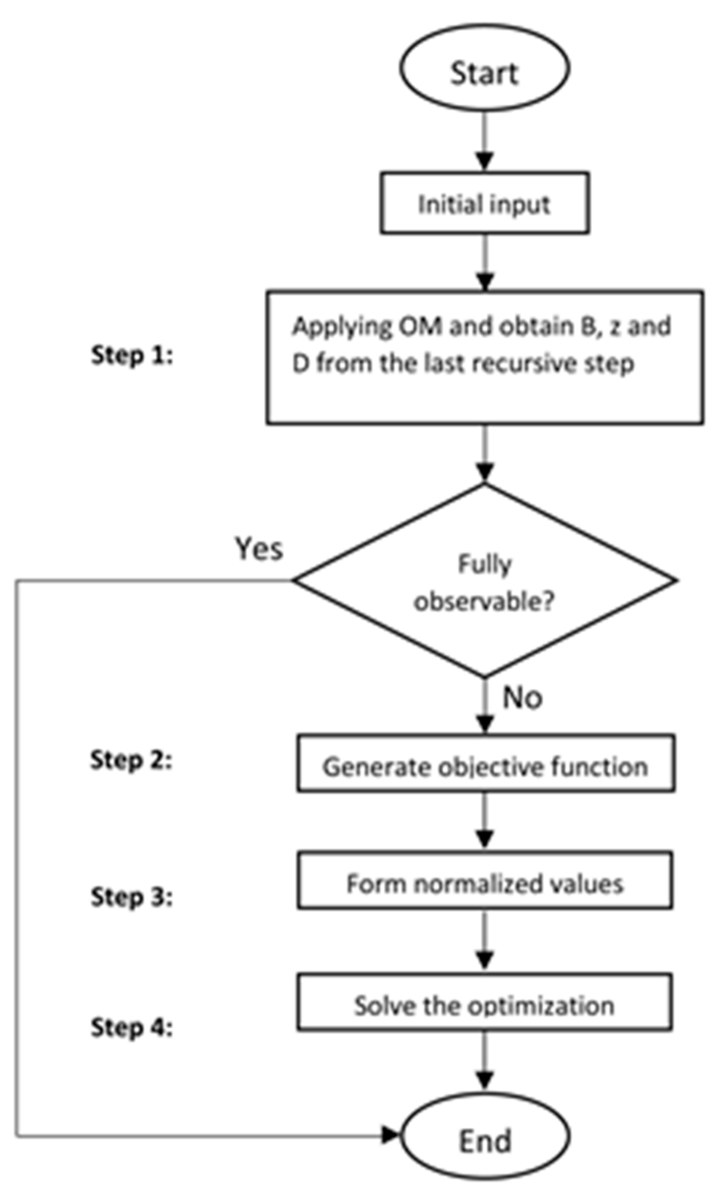
Step 1: Apply SSI by OM to check whether any variable is observed. If all unknown parameters are observed, there is no need to go to the COM process, otherwise, go to step 2.
Step 2: Obtain Eq. (2) from the OM and generate the objective function.
Step 3: Obtain the normalized unknown parameters.
Step 4: Guess the unknown parameters' initial values, apply bounds for the solution and solve the optimization process, in order to find the least acceptable value for vector {∈}.
A summary of the procedure is shown in the flow chart in Fig 2. For more information about the COM, the reader is addressed to [42].
Since the COM method was based on Euler-Bernoulli’s SMM, it was not able to consider the effects of shear deflections. This problem was solved by Emadi et al. [43] who introduced the effects of shear deformation into the COM process. Due to a lack of considering shear rotation in SMM, COM is not able to observe the value of material properties correctly, when rotations are included into the measurement sets. This method is not suitable for measuring rotations as wrong results are obtained even in noise-free measurements when these types of deformations are considered. Emadi studied the effects of this impotence in considering shear rotations in SSI methods based on SMM [44]. It showed the effects of neglecting shear rotation in the inverse analysis were not negligible, even in the cases where beams cannot be considered deep beams (based on Eurocode EN [13] and by the ACI Committee 318 [14]).
In this section, a new procedure is developed to take into account the effects of shear rotations in the SSI of 2-dimensional structures modeled with beam elements.
Providing that a static load test is performed in a structure and measurements are taken from some nodal displacements (total deflections and rotations including bending and shear displacements and rotations), the first step will be trying to separate the bending and shear rotations. Then, firstly, direct analysis is performed assuming those beam elements have their theoretical mechanical properties. Then, the shear rotation of each element is calculated based on the assumed mechanical properties. Equation (4) can be used to calculate shear rotation, vs in each element based on Timoshenko's beam theory.
W s = Q A v G
where Av is the shear area, Q is the shear force and the shear modulus G might be written as:
G = E 2 1 + v
where the coefficient v refers to the Poisson’s ratio. According to Eq. (4), the shear rotation for each element only depends on shear forces, shear area and shear modulus. On the other hand, shear area and shear modulus are directly obtained from the assumed mechanical properties of the structure, while the shear forces can be obtained from the results of the direct SMM analysis. By subtracting the value of shear rotation from the measured rotation of each node the bending rotation can be obtained (it is important to highlight that the measured rotation can be expressed as the sum of shear and bending rotations). Therefore, the COM process can be used as it is based on neglecting shear rotation effects. Once COM provides an estimate of the mechanical properties of the structure, these can be used to calculate new shear rotations. In this way, an iterative process should be performed until the adequate structural response of all the elements is satisfied. In order to limit the computational cost of the optimization process, the stopping criteria are defined: 1) when the iterative process is performed more than 200 times without getting improvement of the solution, and 2) when the difference between values of the observed structural properties in 2 subsequent iterative steps are less than 1e-3.
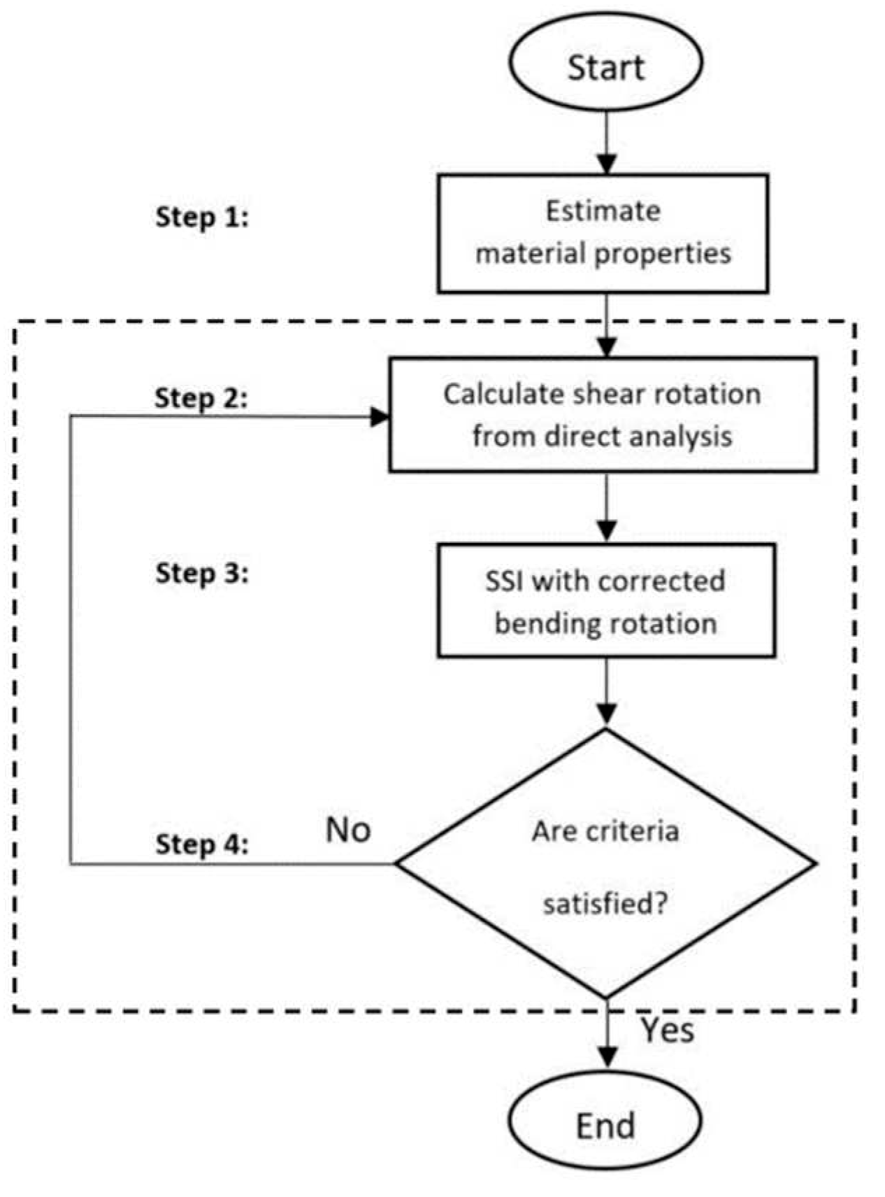
The main steps of this procedure are described as follows:
Step 1: Assumption of the initial values of structural properties, as the theoretical ones
Step 2: Calculate the shear rotation of each element from the assumed structural properties and static loads. It is important to highlight that the stiffness properties can be obtained through either theoretical values (for the first time) or observed structural properties provided by the COM optimization (in the iterative process).
Step 3: Obtain the bending rotation from the calculated shear rotation in Step 2 and perform COM analysis. It is to say that the value of bending rotation for the measured nodes is calculated by subtracting the actual value (measured on-site) from the theoretical shear rotation calculated in Step 2.
Step 4: Check the stopping criteria. If one of them is satisfied, the process stops, otherwise, go to Step 2.
A summary of the procedure is shown in the flow chart in Figure 3. In the following section, a set of structures are analyzed to illustrate the applicability and potential of the proposed method. This will be called 2COM as COM is applied in two steps.

3. Results

To show the applicability of the new method, several academic examples are analyzed in this section. It is important to highlight that in these simulations, no horizontal forces are considered and therefore, the axial resistant mechanisms are not studied as they are not excited. In addition, measurement errors are neglected in the simulations.

3.1. Example 1: simply supported beam with 2 iteration processes

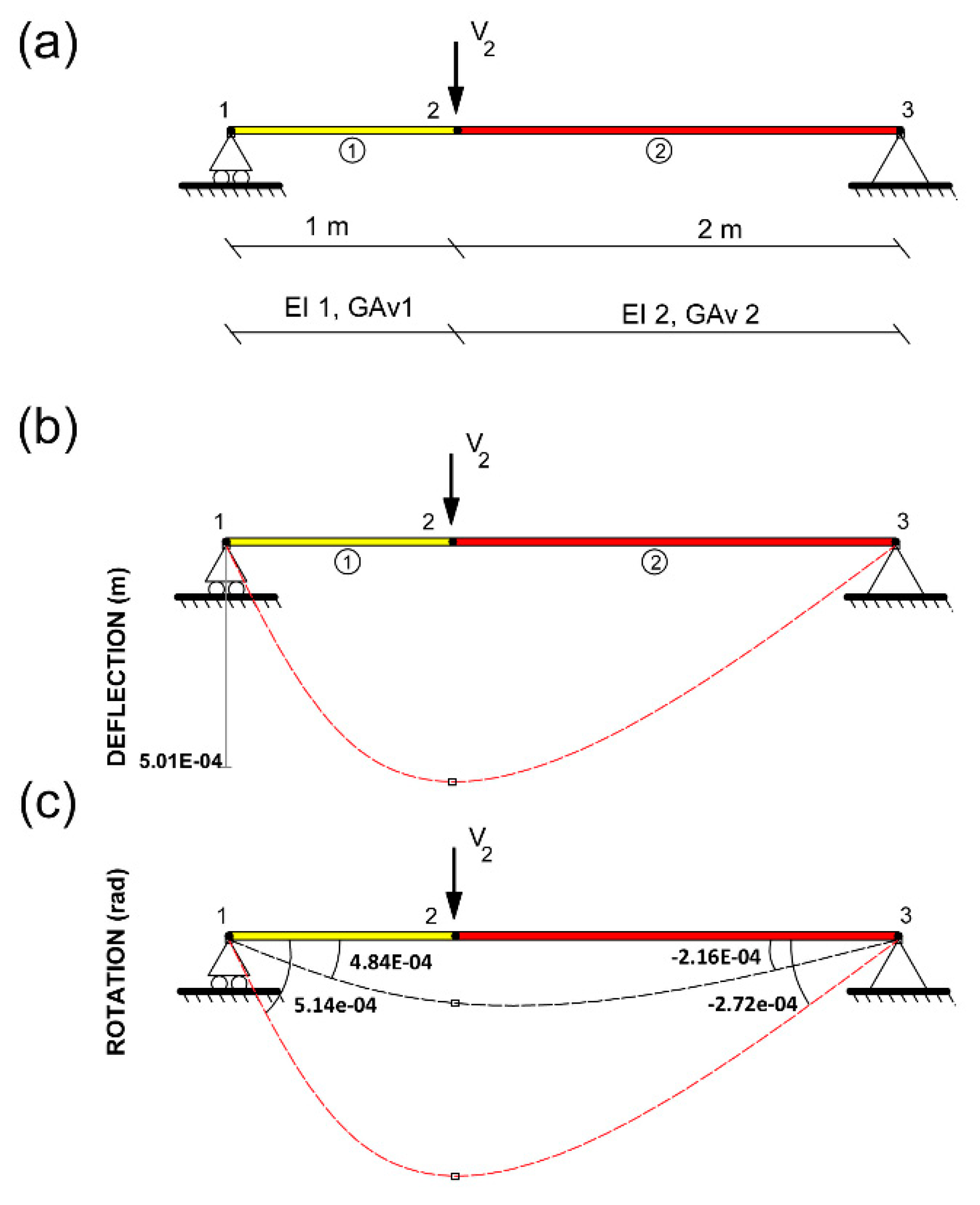
Consider the 4 m long and 0.2 m wide simply supported beam modeled with 3 nodes and 2 beam elements depicted in Figure 4(a). This beam has a constant cross-section and its mechanical properties are listed in Table 1. The boundary conditions of the structure are horizontal and vertical displacements restricted in node 1 and vertical displacement restricted in node 3 (this is to say, u1=v1=v3= 0). The beam is subjected to a concentrated vertical force in node 2 of 100kN (V2= 100kN).
For the inverse analysis of the structure, the load V2, the length of the elements, Poisson’s ratio and Young modulus E are assumed as known, while the inertia, I and the shear area Av for both elements are assumed as unknown. To identify the two unknown parameters (Av and I) a measurement set of at least four rotations is required to identify the values of unknowns. Nevertheless, the analysis of the traditional OM of this model proves that no set of four rotations in OM enables the proper identification of the unknown parameters. Therefore, a set of vertical deflection and a rotation should be measured together (it is to say w1, w2, w3 and v2). The values of the measurement set obtained from Timoshenko’s beam theory simulation can be seen in Figure 4(b) and Figure 4(c).
To check the robustness of the method, a set of random values is chosen for Inertia and Shear area to be used to calculate the hypothetical site measurements. 50 different random sets of the initial value coefficients for the inertia and the shear area were randomly chosen between 0.8 and 1.2 of the theoretical values. These initial parameters are successively updated throughout the iterative process. From 50 analyses, in 3 analyses the optimization process was not convergent to the solution and no result was acquired. The normalized average, standard deviation and coefficient of variation of the remaining results as well as the mode are presented in Table 2.
These results prove the adequate convergence of the proposed methodology in simply supported beams for random initial values of the Inertia. The reason for the flaw in the observed value of GAv2 is that the measuring on node 2 cannot provide sufficient information for covering the shear area of beam number 2. Therefore, the value of the shear area cannot be observed properly. It should be said that even in this situation the new method is able to observe Inertia properly. For the same measurement set, the results of traditional COM (without the ability to consider shear rotations) in this example lack physical meaning. These values illustrate the inability of traditional COM to identify the correct value of parameters as it is not able to identify shear rotations.

3.2. Example 2: Cantilever beam with 2 iteration processes

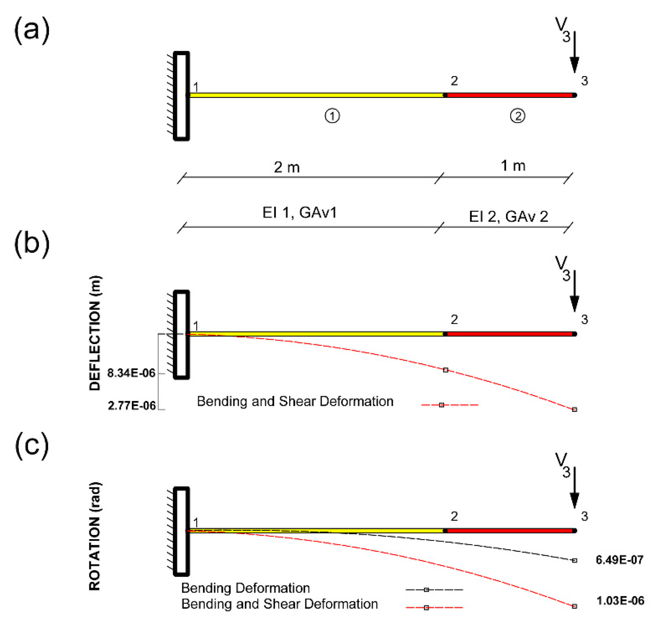
Consider a cantilever beam with the same cross-section and same properties as in Example 3.1 modeled with one beam element and 2 nodes as it is presented in Figure 5. The boundary conditions of the structure are total horizontal and vertical displacements and rotation due to bending restricted in node 1 (this is to say, u1=v1=wb1= 0). The only external force applied is assumed as a concentrated vertical force in Node 3 of 100kN (V3= 100kN). As in the previous example, the length of the elements, L, the Poisson’s ratio and the Young modulus E are assumed as known in the inverse analysis, while the inertia I and the shear area Av for elements 1 and 2 are assumed as unknown. To obtain these four unknown parameters the measurement set should include at least four rotations. Nevertheless, the analysis of the traditional OM proves that no set of four rotations in COM enables the proper identification of the unknown parameters. Therefore, a set of vertical deflection and rotation should be measured together in this example. To perform the COM2, a measurement set that consists of two rotations and two vertical deflections (w2, w3 and v2, v3) is employed. The rotations and the vertical deformations including shear effects of this structure are presented in Figure 5.
To check the robustness of the method, a set of random values is chosen for Inertia and Shear area to be used to calculate the hypothetical site measurements. 50 different random sets of the initial value coefficients for the inertia and the shear area were randomly chosen between 0.8 and 1.2 of the theoretical values. Also, no matter what set of the initial value is chosen, in all circumstances, the obtained values of 2 iterative process have proper convergence to real values of mechanical properties. The normalized average, standard deviation and coefficient of variation of the remaining results as well as the mode are presented in Table 3.
These results prove the adequate convergence of the proposed methodology in cantilever beams for random initial values of the unknown parameters. These results show the applicability of the proposed methodology in cantilever structures. It is important to highlight that obtained results of the original COM process for this example lack physical meaning as ratios of 0.562 and 3.000 were obtained for the Inertia in I1 and I2, respectively.

3.3. Example 3: Application to a composite bridge

To show the application of the proposed methodology to a real structure, the problem of the construction of a bridge by the balanced cantilever method is studied in section 4.
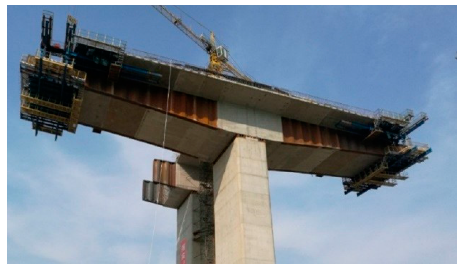
In these structures, deflections should be anticipated in advance in order to calculate how to build the precamber structures in the different segments. To update this precamber structure for every step during construction, complete topographic surveying is usually performed. Therefore, an inverse analysis can be employed for providing information for this model updating process. However, shear effects might not play a very important role for a full developed cantilever, neglecting the effects of shear rotation in the first segment will lead to the unreliable estimation of the bending stiffness. A simplified model of the Yunbao Bridge over the Yellow River in China (see Figure 6) is studied in this section to show the Applicability of the new method to solve this problem. The structure span is 90m long, but only an intermediate construction stage is considered in this example. The studied construction stage includes the construction of two symmetric cantilevers. The length of each deck segment is 4.5m and the length of the segment over the pile is 2.5m. The total length of the model is 29.5 m. The mechanical and material properties defined by the method of the transformed section are listed in Table 4 [46].
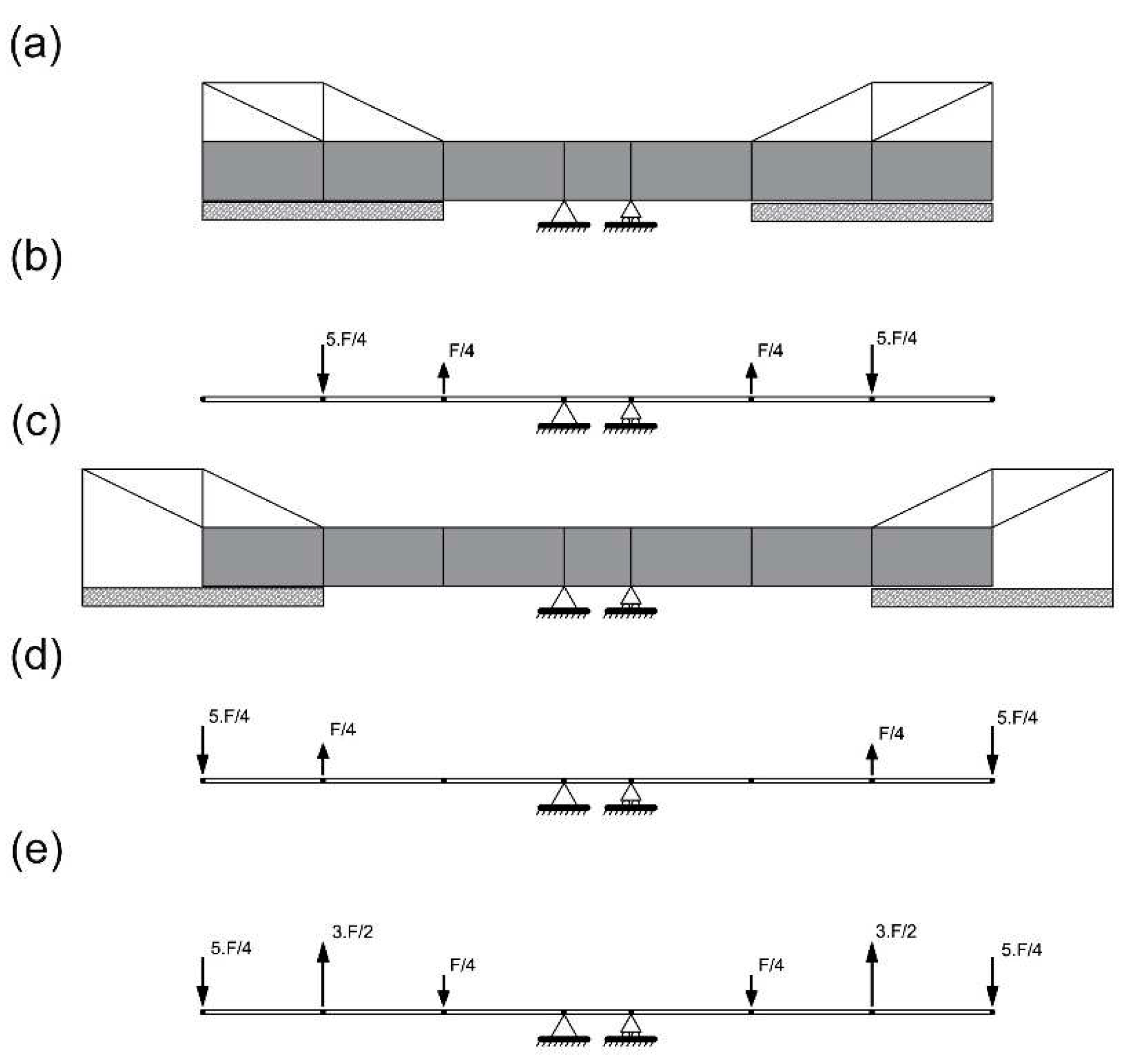
Actual site data is not considered in this structure and the structural response is simulated numerically. The effects of creep and shrinkage in concrete are neglected. The load test used simulates the movement of the formwork traveler (Figure 7). The weight F of the formwork traveler (weight of formwork included) is considered 60 % of the weight of the segment (1041 kN). The effect of each form traveler in the deck is considered two vertical forces. The values of these two forces are 0.25F and 1.25F (226 kN, upwards and 1267 kN, downwards). Load case of the bridge model is calculated by reducing the effects of stage i (Figure 7(a)), from stage i+1 (Figure 7(c)), wherein the formwork traveler is moved forward to the next segment. Load cases of the stages i and i+1 are expressed in Figure 7(b) and 7(d), respectively. The consequent load case introduced in the simulation is shown in Figure 8(e). It is to highlight that the vertical resultant of such forces on each side of the cantilever is zero.
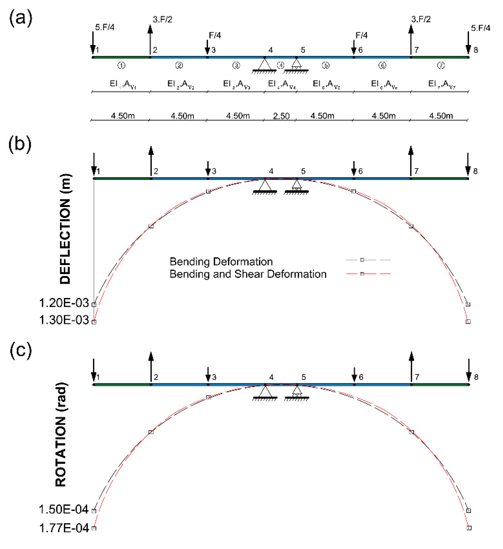
The simplified FEM of this structure is presented in Figure 8. This FEM includes 7 elements and 6 concentrated loads Since there is no axial load, the axial stiffness is not activated in this example; therefore, only flexural and shear behavior is analyzed. As shear stiffness and bending stiffness from elements 2, 3, 4, 5 and 6 are supposed to be observed from the previous construction steps, such properties are considered as known. Hence, shear and bending stiffness of the new built elements are the targets of the analysis (this is to say I1, I7 and Av1, Av7) and are assumed as unknowns.
In this example, there are 4 unknowns (it is to say EI1, GAv1 and EI7, GAv7). In order to identify the 4 unknown mechanical properties, a set of at least 4 measurements is required. The analysis of the OM proves that the COM is not able to observe any structural properties by only measuring rotations in this example. To observe the structural parameters with the proposed methodology, the variation of deflection and rotation should be taken into account (it is to say, w1, v2 and w7, v6). The value of theoretical rotation and vertical deflection of node 1 are presented in Figure 8(b) and 8(c). Timoshenko's beam theory is used to calculate the values of measured variables in node number 1 (the value at node number 7 is the same).
The initial value coefficients of unknown inertia and shear area (I1, I7 and Av1, Av7) were randomly chosen between a ratio of 0.8 and 1.2 of the theoretical values. The 50 analyzed random initial values are performed. Also, no matter what set of the initial value is chosen, in all circumstances, the obtained values of 2 iterative processes have proper convergence to real values of Inertia. The normalized average, standard deviation and coefficient of variation of the remaining results as well as the mode are presented in Table 5.
These results prove the adequate convergence of the proposed methodology in a bridge structure for random initial values of the unknown parameters. These results prove the efficiency of the proposed COM to estimate the inertia when the effects of shear rotations are considered, in case that the shear area cannot be observed by the proposed method. It is to say that traditional COM is not able to identify the value of mechanical properties and it lacks physical meaning when theoretical rotations are measured. In addition, it is important to highlight that, as far as the authors know, no other SSI method based on SMM in the literature is able to include the effects of these rotations in the inverse simulation.

4. Discussion

All Structural System Identification (SSI) methods based on Stiffness Matrix Method (SMM) in the literature neglect shear rotations. This limitation might lead to significant errors when the structural parameters of some structures (such as deep beams) are obtained from actual rotations on site. To fill this gap, the formulation of the Constrained observability method (COM) is updated to include the effects of the shear rotations. This application leads to an iterative process where the initial values of the estimates are successively updated. The applicability of the proposed methodology is illustrated by several academic examples. In addition, to illustrate the applicability of the proposed method on actual structures, a simplified model of an intermediate construction stage of a cantilever composite bridge in China is studied. The results of this study show how the value of structural properties can be observed by COM when the actual rotations are included into the measurement set. This research presents the application of the method for error-free measurement sets. Possible modeling errors have been also neglected.

Author Contributions

Conceptualization, methodology, software, writing—original draft preparation, formal analysis and validation, S.E.; investigation and writing—review and editing, J, L.; resources, funding, and writing—review and editing Y.S.; supervision and project administration, J.T. All authors have read and agreed to the published version of the manuscript.

Funding

The authors are indebted to the National Natural Science Foundation of China (52278308) directed by Yuan Sun; the Spanish Ministry of Economy and Competitiveness for the funding provided through the research project BIA2017-86811-C2-1-R directed by José Turmo and BIA2017-86811-C2-2-R directed by José Antonio Lozano-Galant, and all these projects are funded with FEDER funds. Authors are also indebted to the Secretaria d’ Universitats i Recerca de la Generalitat de Catalunya for the funding provided through Agaur (2017 SGR 1481).

Institutional Review Board Statement

Not Applicable.

Informed Consent Statement

Not Applicable.

Data Availability Statement

The data presented in this study are available on reasonable request from the corresponding author.

Conflicts of Interest

The authors declare no conflict of interest. The funders had no role in the design of the study; in the collection, analyses, or interpretation of data; in the writing of the manuscript; or in the decision to publish the results.

References

  1. Albero, V., Espinós, A., Serra, E., Romero, M.L., Hospitaler, A. Numerical study on the flexural behaviour of slim-floor beams with hollow core slabs at elevated temperature, Engineering Structures, 2019, 180, 561-573. [CrossRef]
  2. C. Turgut, L. Jason, L. Davenne, Structural-scale modeling of the active confinement effect in the steel-concrete bond for reinforced concrete structures, Finite Elements in Analysis and Design, Volume 172, 2020, 103386, ISSN 0168-874X. [CrossRef]
  3. Weaver W., Were J.M. Computer-Oriented Direct Stiffness Method. In: Matrix Analysis of Framed Structures, Springer, Boston, MA, 1990. [CrossRef]
  4. Adam J. Sadowski, On the advantages of hybrid beam-shell structural finite element models for the efficient analysis of metal wind turbine support towers, Finite Elements in Analysis and Design, Volume 162, 2019, Pages 19-33, ISSN 0168-874X. [CrossRef]
  5. Kawano, A., Zine, A. Reliability evaluation of continuous beam structures using data concerning the displacement of points in a small region, Engineering Structures. 2019, 80, 379-387. [CrossRef]
  6. Aguirre, R. Codina, J. Baiges, A variational multiscale stabilized finite element formulation for Reissner–Mindlin plates and Timoshenko beams, Finite Elements in Analysis and Design, Volume 217, 2023, 103908, ISSN 0168-874X. [CrossRef]
  7. Ozdagli, A. I., Liu, B., Moreu, F. Measuring Total Transverse Reference-Free Displacements for Condition Assessment of Timber Railroad Bridges: Experimental Validation, Journal of Structural Engineering, 2018, 144, 040180471.
  8. Liu, S., D Ziemian, R., Chen, L., Chan, S-L. Bifurcation and large-deflection analyses of thin-walled beam-columns withnon-symmetric open-sections, Thin-walled structures, 2018, 132, 287-301.
  9. Dahake, A., Ghugal, Y., Uttam, B., Kalwane, Dr. Displacements in Thick Beams using Refined Shear Deformation Theory, 2014, Proceedings of 3 rd International Conference on Recent Trends in Engineering & Technology.
  10. Tomas, D., Lozano-Galant, J.A., Ramos, G., Turmo, J. Structural system identification of thin web bridges by observability techniques considering shear deformation, Thin-Walled Structures, 2018, 123 282-293.
  11. Dym, C.L., Williams, H.E. Estimating Fundamental Frequencies of Tall Buildings, Journal of Structural Engineering, 2007, 133 1479-1483.
  12. Jun Yan, Baoshun Zhou, Zhixun Yang, Liang Xu, Haitao Hu, Mechanism exploration and effective analysis method of shear effect of helically wound structures, Finite Elements in Analysis and Design, Volume 212, 2022, 103840, ISSN 0168-874X. [CrossRef]
  13. EN 1992-1-1 (2002) Eurocode 2: Design of concrete structures - Part 1-1: General rules and rules for buildings. CEN, Brussels, 2002, Belgium.
  14. ACI committee 318 (2000), Building code requirements for structural concrete and commentary. American Concrete Institute, Detroit, USA.
  15. Timoshenko, S. P. On the correction for shear of the differential equation for transverse vibrations of prismatic bars, Philosophical Magazine, 1921, 41 (6), 742–746.
  16. CSI, (2016), CSI Analysis Reference Manual for SAP2000, ETABS, SAFE and CSiBridge, Berkeley, California, USA.
  17. Pisey Keo, Quang-Huy Nguyen, Hugues Somja, Mohammed Hjiaj, Derivation of the exact stiffness matrix of shear-deformable multi-layered beam element in partial interaction, Finite Elements in Analysis and Design, Volume 112, 2016, Pages 40-49, ISSN 0168-874X. [CrossRef]
  18. Pisano, A.A (1999), “Structural System Identification: Advanced Approaches and Applications”. PhD. Ph.D. Dissertation, Università di Pavia, Italy.
  19. Zhang, F., Yang, Y., Xiong, H., Yang, J., & Yu, Z. Structural health monitoring of a 250-m super-tall building and operational modal analysis using the fast bayesian FFT method, Structural Control and Health Monitoring, 2019, 26(8), e2383. [CrossRef]
  20. Lu, Y., Panagiotou, M. (2014) Three-Dimensional Cyclic Beam-Truss Model for Nonplanar Reinforced Concrete Walls. Journal of Structural Engineering. 140. 04013071. [CrossRef]
  21. Reddy, J. N. (2006) An introduction to the finite element method, McGraw-Hill Education, ISBN: 9780072466850.
  22. Pickhaver, J.A. (2006) Numerical modelling of building response to tunneling. Ph.D. thesis, University of Oxford.
  23. Przemieniecki, J.S. (1968), “Theory of Matrix Structural Analysis”, Library of Congress Catalog Card Number 67, 19151.
  24. Emadi, S.; Ma, H.; Lozano-Galant, J.A.; Turmo, J. Simplified Calculation of Shear Rotations for First-Order Shear Deformation Theory in Deep Bridge Beams. Appl. Sci. 2023, 13, 3362. [CrossRef]
  25. Sirca Jr, G.F., & Adeli, H. System identification in structural engineering, Scientia Iranica, 2012, 19(6), 1355-1364.
  26. Rodrigo L. Pereira, Heitor N. Lopes, Renato Pavanello, Topology optimization of acoustic systems with a multiconstrained BESO approach, Finite Elements in Analysis and Design, Volume 201, 2022, 103701, ISSN 0168-874X. [CrossRef]
  27. Rujie Sun, Guoping Chen, Huan He, Baoqiang Zhang, The impact force identification of composite stiffened panels under material uncertainty, Finite Elements in Analysis and Design, Volume 81, 2014, Pages 38-47, ISSN 0168-874X. [CrossRef]
  28. Gevers, M. A personal view of the development of system identification: A 30-year journey through an exciting field, IEEE Control Systems, 2006, 26(6), 93-105.
  29. Hoang, T., Foret, G., Duhamel, D. Dynamical response of a Timoshenko beams on periodical nonlinear supports subjected to moving forces, Engineering Structures, 2018, 176, 673-680. [CrossRef]
  30. Kim, N. (2009) Dynamic stiffness matrix of composite box beams. Steel and Composite Structures 9(5) 473-497. [CrossRef]
  31. Yildirim Serhat Erdogan, F. Necati Catbas, Pelin Gundes Bakir, Structural identification (St-Id) using finite element models for optimum sensor configuration and uncertainty quantification, Finite Elements in Analysis and Design, Volume 81, 2014, Pages 1-13, ISSN 0168-874X. [CrossRef]
  32. Chatzieleftheriou, S., & Lagaros, N. D. A trajectory method for vibration based damage identification of underdetermined problems, Structural Control and Health Monitoring, 2017, 24(3). [CrossRef]
  33. Hau T. Mai, Tam T. Truong, Joowon Kang, Dai D. Mai, Jaehong Lee, A robust physics-informed neural network approach for predicting structural instability, Finite Elements in Analysis and Design, Volume 216, 2023, 103893, ISSN 0168-874X. [CrossRef]
  34. Yunzhen He, Zi-Long Zhao, Kun Cai, James Kirby, Yulin Xiong, Yi Min Xie, A thinning algorithm based approach to controlling structural complexity in topology optimization, Finite Elements in Analysis and Design, Volume 207, 2022, 103779, ISSN 0168-874X. [CrossRef]
  35. Catbas, Necati & kijewski-correa, tracy & Aktan, A. Structural Identification of Constructed Systems: Approaches, Methods, and Technologies for Effective Practice of St-Id, American Society of Civil Engineers, USA, 2013. [CrossRef]
  36. Dincal, S., & Stubbs, N. Nondestructive damage detection in euler-bernoulli beams using nodal curvatures - part I: Theory and numerical verification, Structural Control and Health Monitoring, 2014, 21(3), 303-316. [CrossRef]
  37. Guoqiang Wei, Pascal Lardeur, Frédéric Druesne, A new solid-beam approach based on first or higher-order beam theories for finite element analysis of thin to thick structures, Finite Elements in Analysis and Design, Volume 200, 2022, 103655, ISSN 0168-874X. [CrossRef]
  38. Ngoc-Tuan Nguyen, Nam-Il Kim, Jaehong Lee, Mixed finite element analysis of nonlocal Euler–Bernoulli nanobeams, Finite Elements in Analysis and Design, Volume 106, 2015, Pages 65-72, ISSN 0168-874X. [CrossRef]
  39. Leblouda, M., Junaid, M.T., Barakat, S., Maalej, M. Shear buckling and stress distribution in trapezoidal web corrugated steel beams, Thin-walled structures, 2017, 113, 13-26.
  40. Emadi, S., Lozano-Galant, J. A. & Turmo, J. Analyzing the effects of shear deformations on the constrained observability method, Bridge Maintenance, Safety, Management, Life-Cycle Sustainability and Innovations, CRC Press, 2021, 3755-3762.
  41. Lozano-Galant JA, Nogal M, Castillo E, Turmo J. Application of observability techniques to structural system identification”, Computer-Aided Civil and Infrastructure Engineering, 2013, 28, 434–450.
  42. Lei, j., Nogal, M., Lozano-Galant, J.A., Xu, D. and Turmo, j. Constrained observability method in static structural system identification, Structural Control and Health Monitoring, 2017, 25 (1), e2040. [CrossRef]
  43. Emadi, S., Lozano-Galant, J. A., Xia, Y., Ramos, G., & Turmo, J. Structural system identification including shear deformation of composite bridges from vertical deflections, Steel and Composite Structures, 2019, 32(6), 731-741. [CrossRef]
  44. Emadi, S. (2020), “Application of observability techniques to structural system identification including shear effects”. PhD. Ph.D. Dissertation, Universitat Politècnica de Catalunya-BarcelonaTech, Barcelona, Spain.
  45. MATLAB and Optimization Toolbox Release (2017b), The MathWorks, Inc., Natick, Massachusetts, United States.
  46. Chen, Y.S. and Yen, B. T. (1980), “Analysis of Composite Box Girders, Fritz Engineering Laboratory Library”, Report N0 380.12.
  47. Dong, X. Zhao, L. Xu, Z. Du, S. Wang, S. Wang, X. and Jin, W. (2017), “Construction of the Yunbao Bridge over the yellow river”, EASEC-15, October 11-13, Xi’an, China.
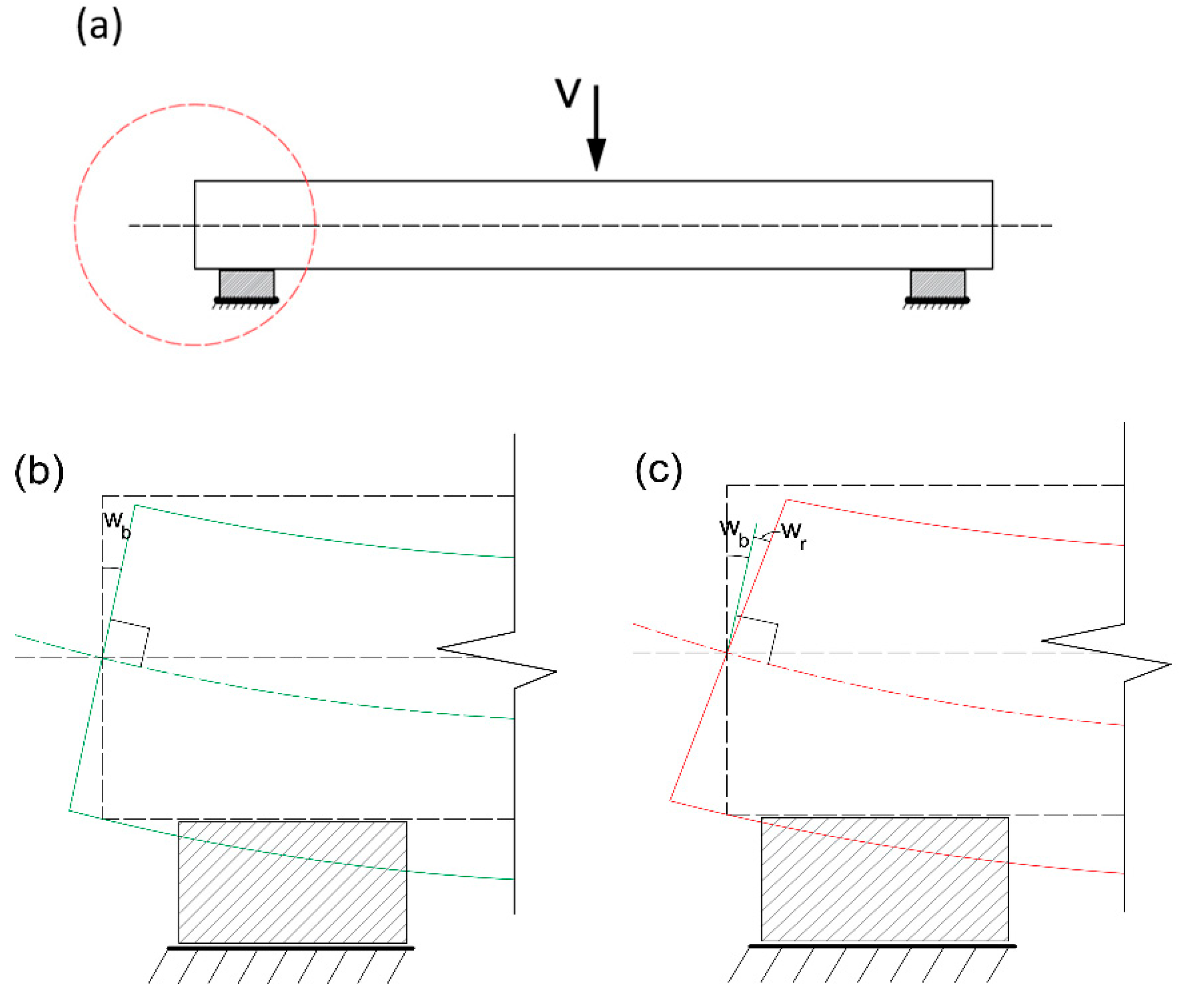
Figure 1. (a) A simply supported beam with a zoomed support. (b) Euler-Bernoulli’s beam theory on the beam support. (c) Timoshenko's beam theory on the beam support.
Preprints 82379 g001
Figure 2. Flow chart of structural system identification by COM.
Preprints 82379 g002
Figure 3. Flowchart of 2COM.
Preprints 82379 g003
Figure 4. Example 1. (a) FEM for a simply supported beam. (b) Deformed shape with the value of bending vertical deformation and with bending and shear vertical deformation at Node 2. (c) Deformed shape with bending rotation and with bending and shear rotation at Node 1.
Preprints 82379 g004
Figure 5. Example 2. (a) FEM for a cantilever beam. (b) Deformed shape with the value of bending vertical deformation and with bending and shear vertical deformation at Node 2. (c) Deformed shape with bending rotation and with bending and shear rotation at Node 2.
Preprints 82379 g005
Figure 6. Composite bridge on-site [47]
Preprints 82379 g006
Figure 7. Definition of the load case: (a, b) Stage i. (c, d) Stage i+1. (e) Load case used for the inverse analysis.
Preprints 82379 g007
Figure 8. Example 3. FEM of the bridge with load case used for inverse analysis. (b) Deformed shape with the value of bending vertical deformation and with bending and shear vertical deformation at Node 1. (c) Deformed shape with bending rotation and with bending and shear rotation at Node 1.
Preprints 82379 g008
Table 1. Properties of the FEM of the simply supported beam.
Properties Value
axial stiffness [GPa·m2] 440.65
shear stiffness for node 1 [GPa·m2] 344.05
shear stiffness for node 2 [GPa·m2] 385
flexural stiffness for node 1 [GPa·m4] 1,246.7
flexural stiffness for node 2 [GPa·m4] 1,120
Table 2. Obtained results from random initial values
parameter average CoV standard deviation
EI1 1.000 8.791e-7 8.791e-7
EI2 1.000 9.114e-7 9.114e-7
GAv1 1.000 0.000 0.000
GAv2 0.910 0.128 0.116
Table 3. Obtained results from random initial values.
parameter average CoV standard deviation
EI1 1.000 8.783e-7 8.783e-7
EI2 1.000 9.118e-7 9.117e-7
GAv1 1.000 0.000 0.000
GAv2 1.000 0.000 0.000
Table 4. Properties of the Finite Element Model of the Bridge.
Properties Value
area [m2] 12.52
shear area [m2] 9.83
inertia [m4] 35.62
steel young’s modulus [GPa] 210
concrete young’s modulus [GPa] 35
poisson’s ratio γ 0.3
Table 5. Obtained results from random initial values.
parameter average CoV standard deviation
EI1 1.000 8.237e-7 8.237e-7
EI2 1.000 8.903e-7 8.903e-7
GAv1 0.617 0.740 0.456
GAv2 0.256 0.305 0.078
Disclaimer/Publisher’s Note: The statements, opinions and data contained in all publications are solely those of the individual author(s) and contributor(s) and not of MDPI and/or the editor(s). MDPI and/or the editor(s) disclaim responsibility for any injury to people or property resulting from any ideas, methods, instructions or products referred to in the content.
Copyright: This open access article is published under a Creative Commons CC BY 4.0 license, which permit the free download, distribution, and reuse, provided that the author and preprint are cited in any reuse.
Prerpints.org logo

Preprints.org is a free preprint server supported by MDPI in Basel, Switzerland.

Subscribe

© 2024 MDPI (Basel, Switzerland) unless otherwise stated