1. Introduction
The process of harvesting infrared (IR) energy involves capturing IR radiation and converting it into renewable energy. The benefits of IR energy scavenging are numerous and include wide availability, high energy density, low cost, sustainability, and low maintenance, as evidenced by several studies [
1,
2]. As a cost-effective and sustainable alternative to traditional energy sources, it is gaining popularity in various renewable energy applications, especially in comparison to commonly used photovoltaic solar cells. However, despite its advantages, solar technology for IR energy harvesting has its limitations, including weather dependence, limited efficiency, high initial cost, large surface area requirement, environmental impact, and storage and transmission complexity, making it unsuitable for all locations [
3,
4]. Additionally, a significant portion of the sun's energy in the IR band (700 nm - 106 nm) remains untapped by conventional solar panels.
MIM or metal-insulator-metal rectennas are developed for the harvesting of IR energy at 10.6 µm (maximum emissivity point in IR band) [
3]. The antenna arms act as the metal components while the insulator is placed between the feeding point of the used antenna structure to make it a MIM rectenna for THz operation. Nano-optical antennas absorb the energy at 10.6 µm which is then rectified by the tunneling diodes. The literature contains various optical antenna structures [
2,
5,
6,
7,
8,
9,
10,
11] for IR energy harvesting in the THz band. Array-based antenna configurations are reported to increase the receiver antenna gains with more captured solar radiations [
12,
13]. However, despite of feeding of more energy to the rectifier by the large size of such structures [
12,
13], rectification stage losses reduce the overall conversion efficiency.
MIIM rectenna, or metal-insulator-insulator-metal rectenna, is an advanced type of rectifying antenna that offers several advantages over traditional MIM rectennas [
14,
15]. These advantages include (i) higher efficiency because of more absorption of electromagnetic energy, (ii) better impedance matching and thus less energy loss during conversion with higher rectification efficiency or responsivity (iii) better tolerance to fabrication variations, (iv) more stable output for consistent output power generation, (v) wider operational frequency range, (vi) potential for integration with other semiconductor materials because of an additional insulator layer, and (vii) low power consumption [
14,
16,
17].
The performance of a MIIM rectenna can be further enhanced by combining it with a metasurface superstrate. The metasurfaces can be used to focus the incoming infrared and light waves for enhanced energy conversion [
18,
19,
20,
21]. The localized surface plasmons can be achieved using metasurfaces in the infrared range [
19,
22,
23] and this too decreases the overall harvester structure as compared to reported large-size array configurations [
12,
13] for the same purpose.
Manar
et al. [
23,
24] reported various slit-based metasurface structures to study the absorption of 9 µm and 10 µm IR radiations using the phase modulation technique. The proposed structures in [
23,
24] achieved transmission efficiencies of 46% and 74.33% for the harvesting of energy from the Earth’s back radiations at 10 µm. Authors in [
25] demonstrated a thermal MIM integrated metasurface with peak emissivity resonances at 5.21 µm and 3.54 µm respectively for scavenging of joules heating. A chiral L-shaped metasurface designed for the localization of IR radiations at 45.2 THz and 53.15 THz based on a phase cancellation approach is reported in [
22]. The study reported the only absorption characteristics of the designed structure in the range of 40-55 THz. An all-dielectric single-layer germanium-based metasurface absorber working in the range of 800 -1600 nm is presented in [
26]. Dorodnyy
et al. [
27] employed a circuit analysis approach for the absorption characteristics analysis of a large-scale model of the Al-SiO
2-Al metasurface. A circular MIIM plasmonic resonator with indium tin oxide (ITO) and SiO
2 as gating material with a DC biasing of metasurface structure is reported in [
19] for the enhanced transmission characteristic at 1650 nm. Recently Yahyaoui
et al. [
14] discussed the field enhancement and rectification characteristics of a log-spiral-based MIIM rectenna only. The existing literature primarily focuses on individual MIM/MIIM structures or metasurface analysis, leaving a gap in the comprehensive characterization of the combination of MIIM structures with integrated metasurfaces. Furthermore, even studies that incorporate MIIM structures and metasurfaces have largely only analyzed their absorption properties, as seen in [
19]. This highlights the need for a more thorough investigation of the MIIM-metasurface combination for a broader range of performance metrics.
This study presents a novel approach for enhancing the harvesting of infrared radiations through the design of a MIIM rectenna with an integrated metasurface (meta lens) as a superstrate. By incorporating a resonating meta lens at 28.3 THz with the rectenna, the captured solar radiation levels are significantly improved. The helical (log-spiral) nanoantenna with the meta lens on top of it generates coherent localized plasmonic oscillations when excited by the incident IR radiations. The resonance frequency of these oscillations depends on the metasurface structure and the surrounding materials [
22,
25,
26]. The MIIM-based rectification structures then efficiently scavenge energy from these localized surface plasmonic waves. The study also thoroughly analyzes the impact of different MIIM materials configurations on the received electric field and rectification parameters (I/V characteristics, resistivity, and responsivity) for four symmetric and asymmetric metals combinations (gold (Au), aluminum (Al), silver (Ag), and copper (Cu)) and four pairs of insulators (aluminum oxide – copper oxide, aluminum oxide – titanium oxide, aluminum oxide – zinc oxide, and titanium oxide -copper oxide), with and without the added meta lens. These pairs of insulators are selected based on their superior performance from the analysis of ten different insulator combinations in a previous study [
14]. The numerical analysis is carried out using CST microwave studio software for the frequency range of 28 to 29 THz.
Further details about the design, analysis, and characterization of the proposed log-spiral-based MIIM structure with meta-lens are presented in the subsequent sections.
2. MIIM Rectenna with a Meta Lens
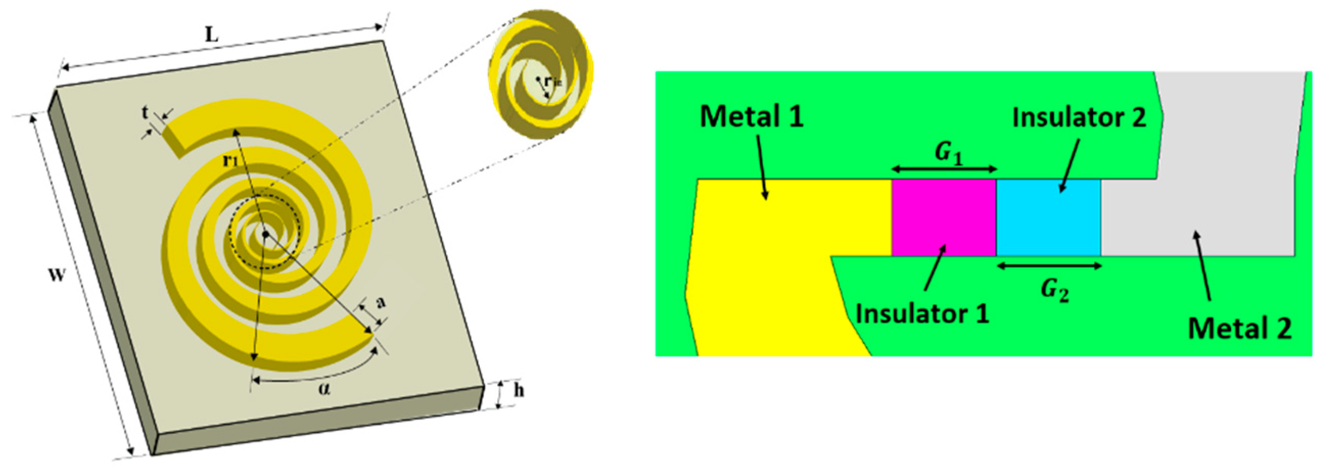
An optimized MIIM rectenna using a log-spiral antenna as an energy-capturing terminal is designed and is shown in
Figure 1. A helical antenna exhibiting resonating wideband operation around 28.3 THz is realized. The illustrated design parameters of the nanoantenna in
Figure 1(a and b) are further optimized from [
14] structure for enhanced field enhancement characteristics. Table 1 lists the optimized geometrical parameters of
Figure 1(a) log-spiral IR antenna. The metal arms of the antenna, acting as metals in MIIM rectenna, are engraved on a quartz substrate (ε = 3.78 and tan δ = 0.0001) of the same length and width of 7.37 µm. The insulators (insulator 1 and insulator 2) are sandwiched between the antenna feeding point of the antenna with widths G
1 and G
2 (see
Figure 1-b). The optimized insulator dimensions are 1 nm (Y
G) and 2 nm (G
1 and G
2). The thickness of the quartz substrate is 99.1 µm. Further details about the rectenna design can be seen in [
14].
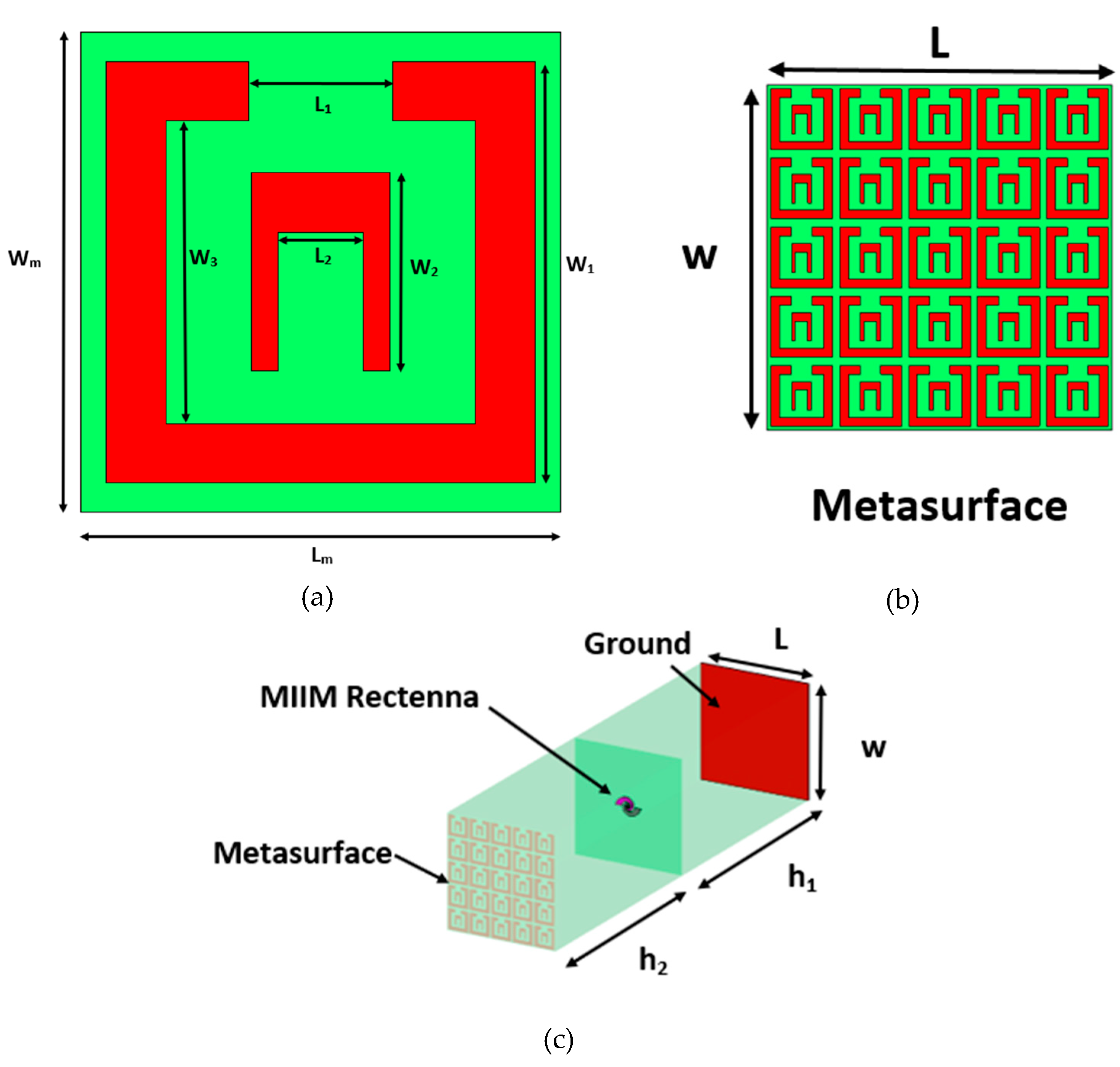
Next, a square split ring unit cell is designed to focus the illuminating IR radiation with a wavelength of 10.6 µm.
Figure 2(a) shows the designed unit cell. The optimized dimensions of unit cell are W
m = 1.4 µm, L
m = 1.4 µm, W
1 = 1.29 µm, W
2 = 0.6 µm, W
3 = 0.92 µm. L
1 = 0.44 µm, and L
2 = 0.26 µm. A metasurface lens constituting a period structure of a realized unit cell is designed and is depicted in
Figure 2(b). This meta lens of 7.37 µm x 7.37 µm is engraved on a quartz substrate and is placed on the top of the MIIM rectenna as shown in
Figure 2(c). In addition, a ground plane is added at the back of the MIIM rectenna for the enhanced absorption of the incoming IR radiations.
Firstly, the full-wave numerical analysis of
Figure 1 (a) structure for four different combinations of used high conductivity and thermally stable metals (Au, Al, Ag, and Cu) with and without added meta lens is performed for the captured field levels. After that two insulators are inserted in the gap between the antenna terminals and the characterization of field enhancement, current/voltage, resistivity, and responsivity of the designed MIIM rectenna with the added metasurface superstrate is done. The localized transfer of captured IR radiations through the insulators for the rectification purpose minimizes the impedance mismatching and thus enhances the overall conversion efficiency [
15,
28].
The numerical analysis is performed in the frequency range of 28 to 29 THz using CST Microwave Studio software. CST employs the finite integration (FIT) method for the electromagnetic and optical characterization of the designed structure. The behavior of metals and insulator vary with the increase in the frequency range. For this purpose, the Drude-Lorentz model has been used for the modeling of the optical frequency-dependent properties of metals at the analyzed THz frequencies. It is a classical model that describes the free electrons in a metal as a gas of oscillators with a frequency-dependent damping term which is critical for the modeling of plasmonic properties of tunneling electrons for the analysis frequency range [
5,
6]. The model is often used to describe the absorption and reflection of THz radiation by metal surfaces and is particularly useful for understanding the behavior of metal surfaces in rectennas. The Drude-Lorentz model is used to optimize the design of the rectenna antenna, and MIIM structure with and without the added meta lens to maximize its performance and efficiency.
3. Field Characterization of Nano-Antenna
The field absorption properties of the structure are analyzed for both symmetric and asymmetric
Figure 1(a) design. For the symmetric design, both spiral arms are assigned gold (Au) material. The second arm metal properties are changed to aluminum (Al), silver (Ag), and copper (Cu) to get the asymmetric configurations of Au-Al, Au-Ag, and Au-Cu.
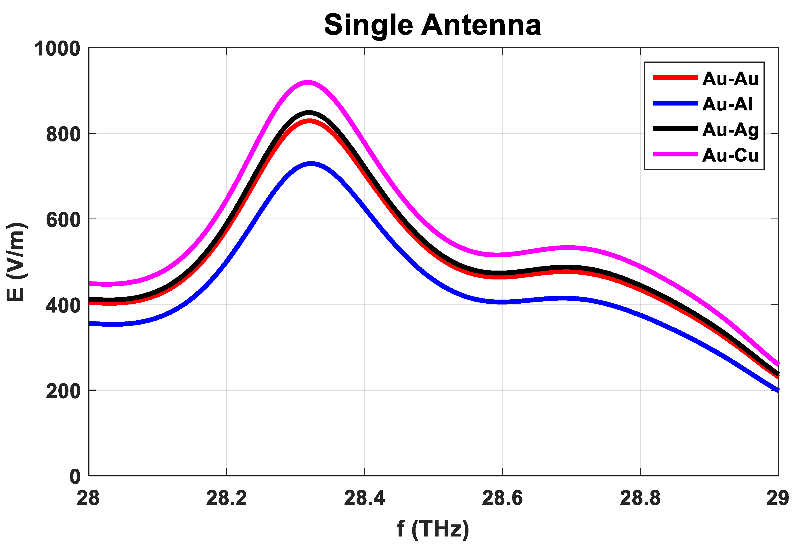
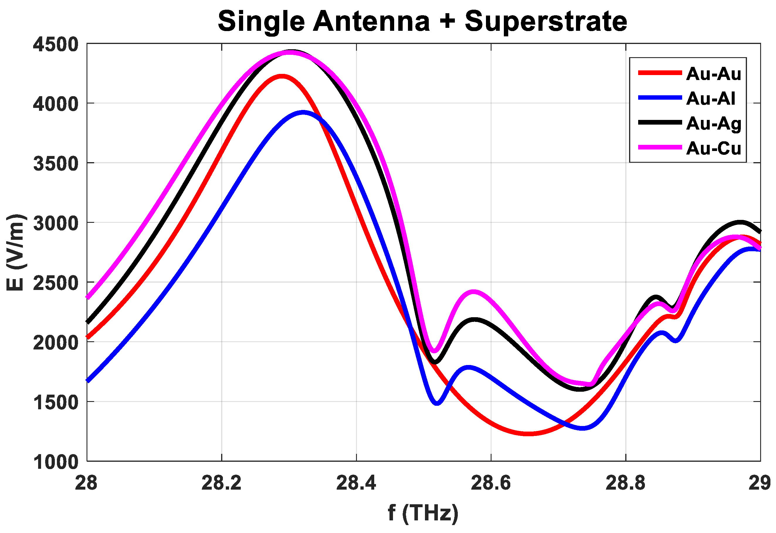
Figure 3 and
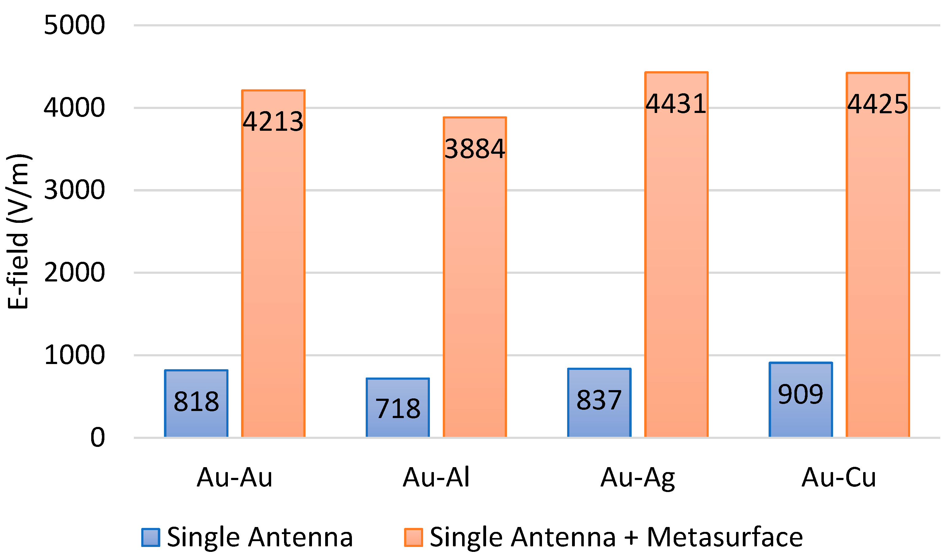
Figure 4 present the comparison of the captured electric field by the spiral antenna only with and without the metasurface superstrate. At the maximum emissivity point of 28.3 THz, the recorded values of the field for symmetric cases with and without added metasurface are 818 V/m and 4213 V/m. This shows the meta lens is successfully focusing the incident IR radiations to the antenna terminal which has resulted in significant improvement (415 %) in the induced E-field levels. The comparison of maximum captured E-field levels for the simulated cases is reflected in
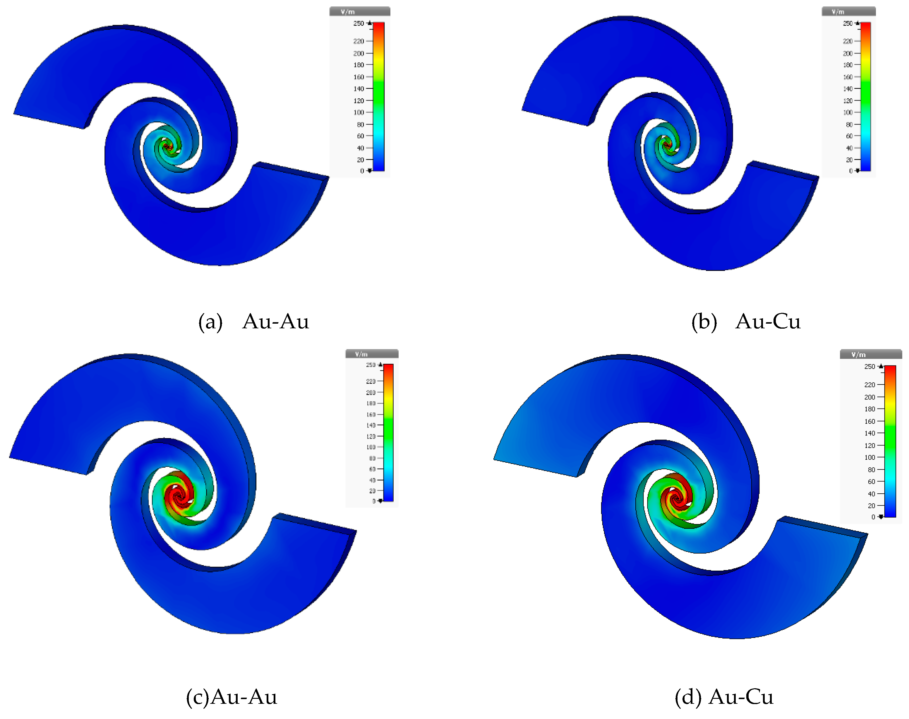
Figure 5. It can be noted that the addition of a meta lens is handy as it produces huge improvement in the field enhancement levels of the antenna for all cases. This can be confirmed by comparing the electric field distributions of log-spiral antenna for selective metal pairs in
Figure 6 with and without added meta lens. For brevity, the E-field spreading on antenna structure at 28.3 THz is reported only for selective pairs of Au-Au and Au-Cu for both with and without metasurface cases.
The higher concentration of induced E-field between the antenna arms gap (G) can be noted in
Figure 6c,d for the case of the antenna when the metasurface is used as a superstrate.
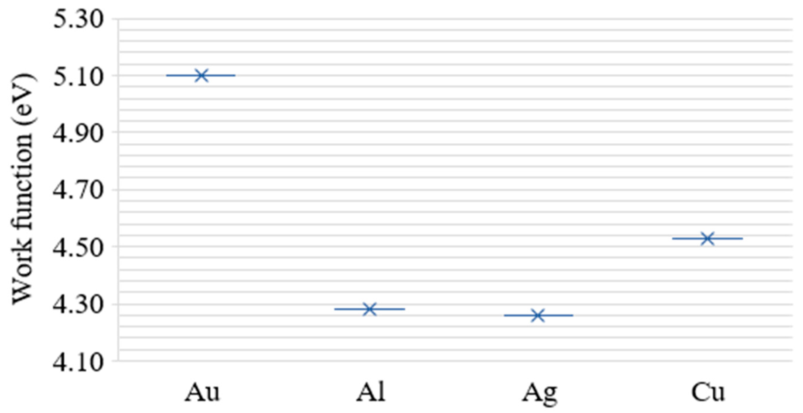
The asymmetric configuration of gold (Au) and copper (Ag) as the antenna arm material is the best case that reported the maximum captured E-field level of 4431 V/m. There is an improvement of 430% for this case. This can be attributed to the larger difference (~0.84 eV) between the works functions of these high conductivity metals (Au, and Ag).
Figure 7 compares the work functions of used high-conductivity metals [
14]. The relatively higher work function of Au makes it less efficient for electron emissions as compared to other used metals. However, combing it with lower work function metals (Al, Ag, and Cu) produces a balance of properties that makes them suitable for the THz antenna terminals. The observed field enhancement in the case of Au-Al is around 440% (the difference of work function is around 0.82 eV) with the addition of the meta lens on the top of the THz spiral antenna. The difference in work function between Au and Cu is smaller (0.57 eV) as compared to Au-Al and Au-Ag pairs. This makes it less efficient than Al and Ag for the electron emissions and thus produces lesser enhancement in the field as compared to those pairs.
4. Field Characterization of MIIM Rectenna with Meta Lens
The double insulator M-I1 I2-M rectenna is formed by sandwiching the two insulators with a width of G1 and G2 between the antenna feeding points as depicted in
Figure 1(b). The chosen insulators for this study are aluminum oxide (Al
2O
3), copper oxide (Cu
2O), titanium oxide (TiO
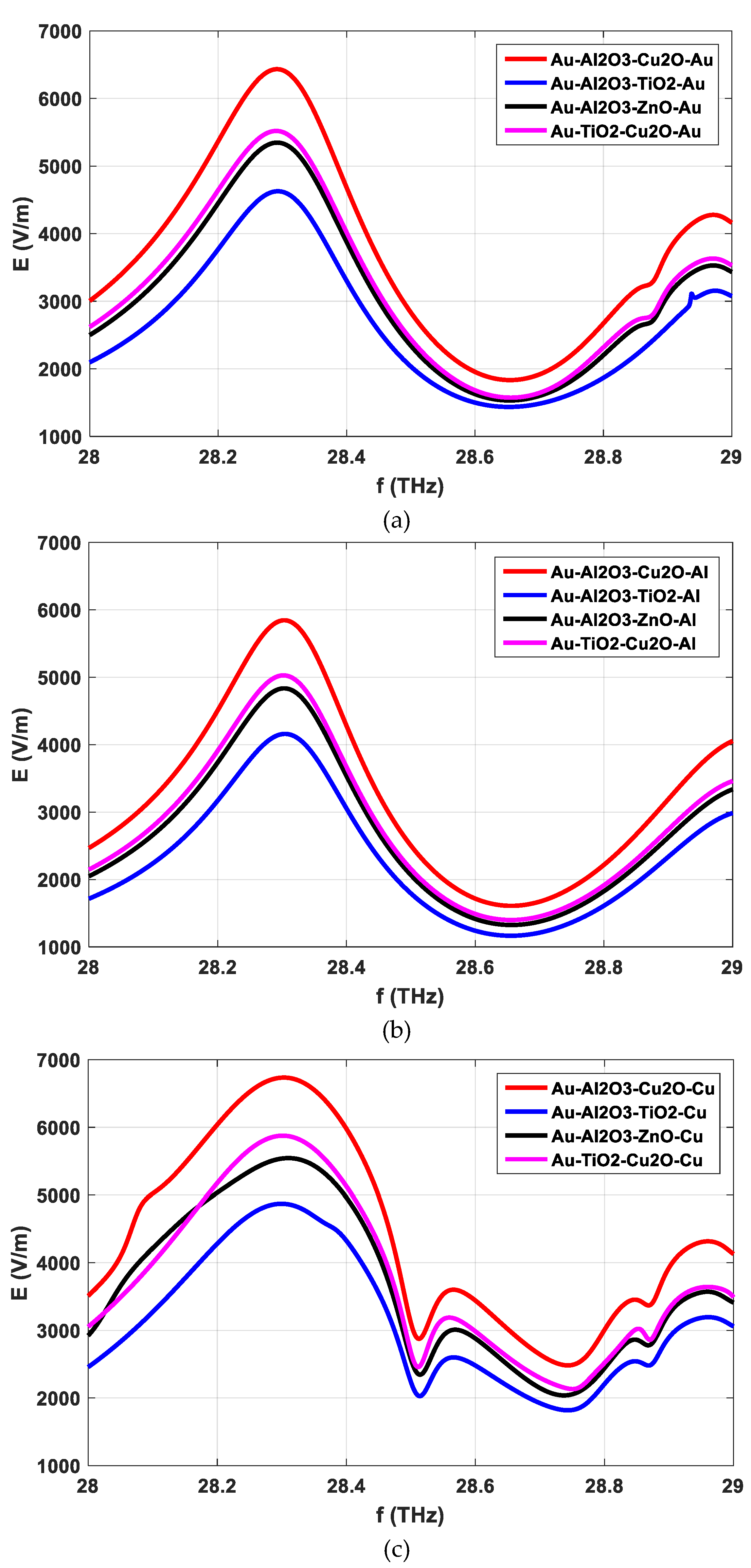
2), and zinc oxide (ZnO). The E-field characterization (see comparison curves in
Figure 8) of the M-I1 I2-M rectenna with integrated metasurface on top of it, is done by using the Al
2O
3 – Cu
2O, Al
2O
3 – TiO
2, Al
2O
3 – ZnO, and TiO
2 - Cu
2O as the double insulator’s combinations. These four insulator and metal combinations are chosen as these are the best-performing pairs among the analyzed ten different such pairs in [
14] for a MIIM rectenna only. The used insulator has electron affinities of 2.58 (Al
2O
3) [
29], 3.2 eV (Cu
2O) [
30], 3.9 eV (TiO
2) [
31], and 4.1 eV (ZnO) [
31] respectively.
The comparison waveforms of induced E-field levels for Au-I1 I2-Ag are not reported here for brevity as the trend of curves is similar to those in
Figure 8 results. It can be noted from
Figure 8 curves that the maximum values of the incoming IR radiation are recorded at 28.3 THz for all the analyzed combinations of metals and insulators. For Au-I1 I2-Au MIIM rectenna with metasurface, the insertion of Al
2O
3 – Cu
2O, Al
2O
3 – TiO
2, Al
2O
3 – ZnO, and TiO
2 - Cu
2O as insulator pairs produces the peak E-field levels of 6431 V/m, 4623 V/m, 5344 V/m, and 5516 V/m. These maximum values changed to 5845 V/m, 4159 V/m, 4834 V/m, and 5026 V/m with the change in metals to Au and silver as depicted in
Figure 8b waveforms. A similar trend of variations in peak E-values is noticed in
Figure 3c curves.
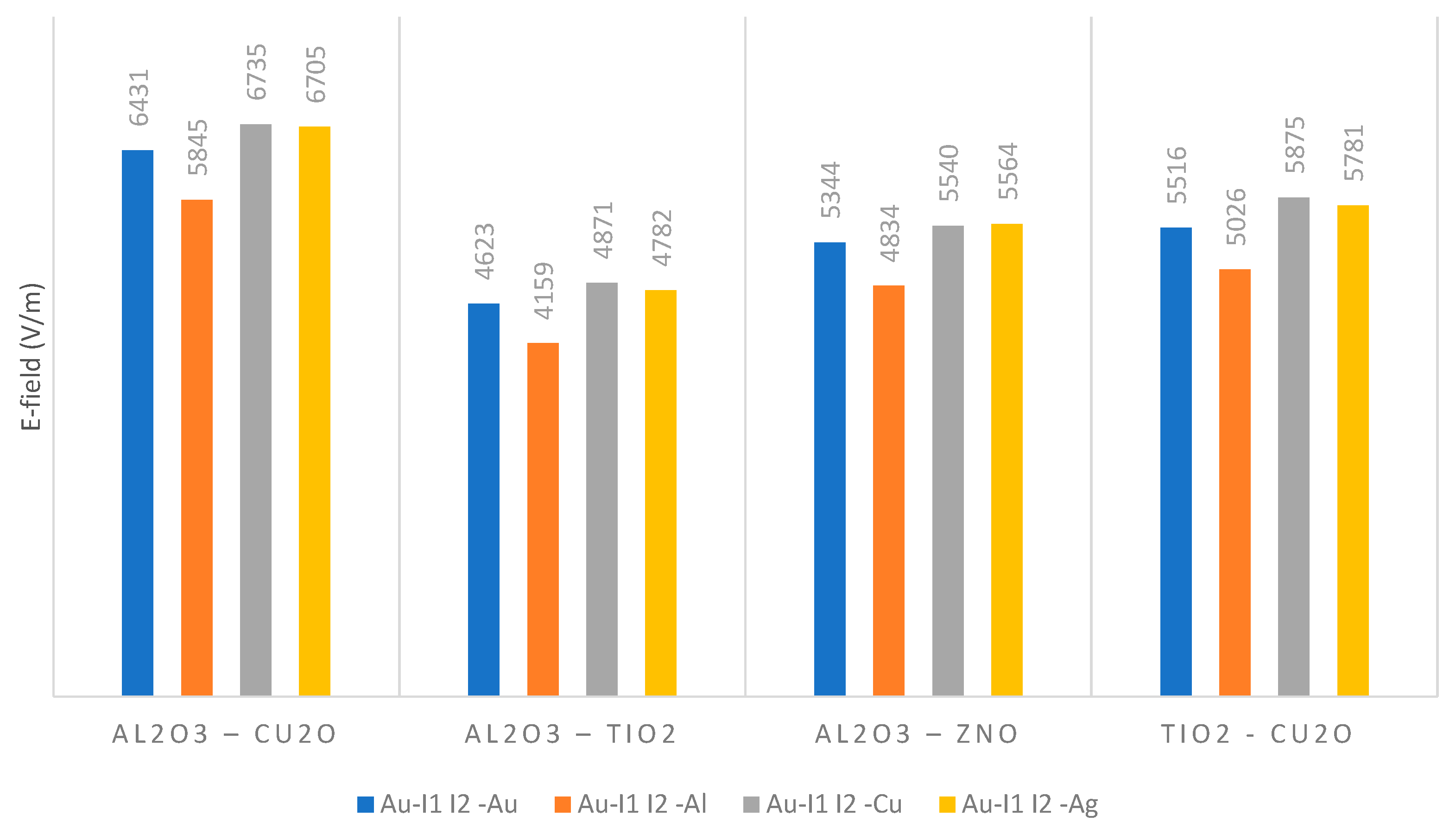
The comparison of the maximum induced E-field at 28.3 THz for all analyzed metal combinations of M-I1 I2-M is presented in
Figure 9. This comparison reflects that the overall best-performing insulator pairs in analyzed MIIM rectenna configurations are Al
2O
3 – Cu
2O and TiO
2 - Cu
2O respectively. The performance of Au-Al
2O
3 – Cu
2O-Au, Au-Al
2O
3 – Cu
2O-Al, Au-Al
2O
3 – Cu
2O -Cu, and Au-Al
2O
3 – Cu
2O-Ag MIIM configurations is superior with recorded E-field levels of 6431 V/m, 5845 V/m, 6735 V/m, and 6705 V/m respectively. As like without insulator cases in
Figure 6, the asymmetric metal combinations of Au-Ag and Au-Cu as MIIM metals reported the highest level of captured electric fields. It is observed from
Figure 9 that the worst filed enhancement characteristics are obtained when the combination of aluminum oxide and titanium oxide is used as insulators in the MIIM rectenna.
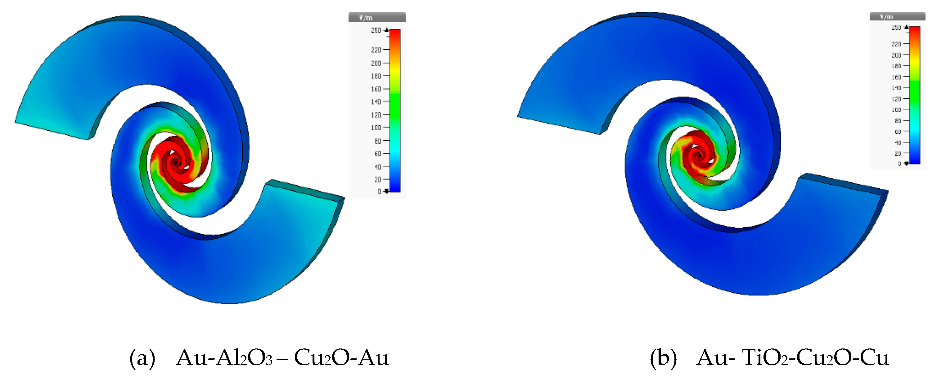
The comparison of the electric field distribution of two cases (Au-Al
2O
3 – Cu
2O-Au, Au- TiO
2-Cu
2O-Cu) of
Figure 9 combinations is reflected in
Figure 10. For brevity, the spreading of E-field is not reported here for the rest of the cases. This confirms that even with the symmetric metal choices, the rectenna performs well in terms of absorbed E-field concentration around the antenna gap with aluminum oxide and copper oxide as insulators. These results are per
Figure 9 where the observed peak E-field values for these cases are 6431 V/m (Au-Al
2O
3 – Cu
2O-Au) and 5875 V/m (Au-TiO
2-Cu
2O-Cu) respectively.
The results of the E-field characterization of the MIIM structure with a metasurface support the findings of a previous study [
14]. In [
14], it was observed that the top-performing pairs of insulators in a MIIM rectenna without a metasurface were Al
2O
3-Cu
2O and TiO
2-Cu
2O. However, the maximum field enhancement levels reported in [
14] for a similar MIIM rectenna structure without an added meta lens were approximately 70% lower compared to the results shown in
Figure 9 of this study. This observation underscores the significance of the proposed design of the MIIM rectenna with the resonating metasurface as its superstrate.
5. Rectification Characterization of MIIM Rectenna
This section provides a detailed analysis of the rectification performance of the MIIM rectenna design proposed in this study. The rectification characterization is conducted by computing the current voltage (I/V), resistivity (R), and responsivity (S) [
17] of the discussed rectenna configurations. The I/V characteristics are used to determine the flowing current through the rectifier for the applied voltage. The resistivity analysis is performed to assess the impedance-matching properties of the rectifier, which are essential for reducing power loss [
32]. The non-linear characteristics of the rectifier are determined through its responsivity, which measures the ability of the rectifier to convert the absorbed IR radiations into an electrical signal. The formulas and procedures described in [
14,
17,
32] are used to compute the aforementioned performance metrics shown in
Figure 2 for the proposed MIIM rectenna design.
The I/V, R, and S characterization of the designed MIIM rectenna is done for different metals and insulator combinations as in
Section 3 and
Section 4. However, here the rectification waveform results are only reported for the top-performing insulator combinations i.e. Al
2O
3-Cu
2O and TiO
2-Cu
2O.
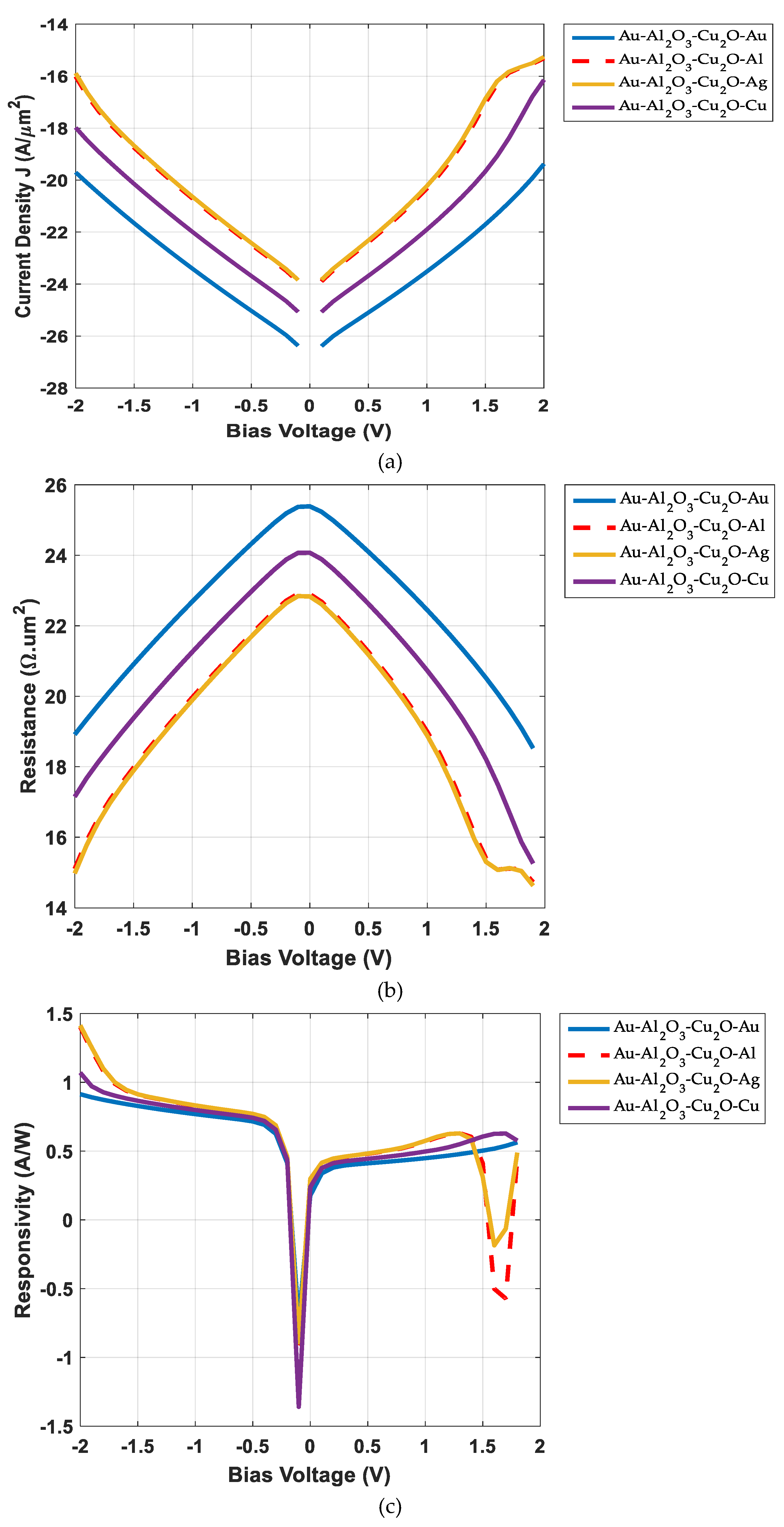
Figure 11 presents the I/V, R, and S waveforms of the M-Al
2O
3-Cu
2O-M rectenna. The depicted waveforms in
Figure 11 are in log scale (log10(J), log10(R), and log10(S)) for better illustration and comparison. The comparison of current density versus biasing voltage is shown in
Figure 11(a) with the change in the second arm material of the log spiral from gold to aluminum, silver, and copper. The biasing voltage is varied within the range of -2 V to 2V for all characterizations. The maximum values of current densities for Au-Al
2O
3-Cu
2O-Au, Au-Al
2O
3-Cu
2O-Al, Au-Al
2O
3-Cu
2O-Ag, and Au-Al
2O
3-Cu
2O-Cu cases are 4.16 x 10
-20 A/µm
2 (-19.3 dB A/µm
2), 4.8 x 10
-16 A/µm
2 (-15.3 dB A/µm
2), 5.53 x 10
-16 A/µm
2 (-15.26 dB A/µm
2), and 7.17 x 10
-17 A/µm
2 (-16.14 dB A/µm
2) respectively. These peak values are obtained for the biasing voltage of 2V. It can be noted from
Figure 11(a) that the integration of the same metals (Au) at both electrodes of the MIIM rectenna with added metasurface produces the worst I/V performance. The work functions of aluminum (Al) and silver (Ag) are similar (see
Figure 7). This resulted in similar I/V curves for the cases of Au-Al
2O
3-Cu
2O-Al and Au-Al
2O
3-Cu
2O-Ag as shown in
Figure 11(a).
The inverse of the first derivative of the average current with respect to the biasing voltage (-2 V to 2V) is taken to compute the resistivity performance of the rectenna.
Figure 11(b) compares the resistivity (in log scale) of the analyzed cases of the MIIM rectenna with the aluminum oxide and copper oxide as the sandwiched insulators. The maximum resistivity is observed at near-zero bias operations in all cases. The peak R values for Au-Al
2O
3-Cu
2O-Au, Au-Al
2O
3-Cu
2O-Al, Au-Al
2O
3-Cu
2O-Ag, and Au-Al
2O
3-Cu
2O-Cu configurations are 2.45 x 10
25 Ω.µm
2 (25.3 dB Ω.µm
2), 8.01x 10
22 Ω.µm
2 (22.9 dB Ω.µm
2), 6.96 x 10
22 Ω.µm
2 (22.84 dB Ω.µm
2), and 1.18 x 10
24 Ω.µm
2 (24.07 dB Ω.µm
2) respectively. Contrary to the I/V performance, the symmetric MIIM structure (Au-Al
2O
3-Cu
2O-Au) has higher near zero-bias resistivity. The performance of the gold and copper metals as the electrodes of the M- Al
2O
3-Cu
2O-M rectenna with metasurface is better than the cases when the second electrode of the rectenna constitutes Al or Ag metals. A relative decrease in the maximum resistivity is noted with the change in second antenna aram metals to Al, Ag and Cu. As with I/V characteristics, the resistivity curves of rectenna with aluminum and silvers as the second electrodes are similar.
The rectification efficiency in terms of the responsivity of the rectenna is calculated by multiplying the resistivity with the second derivate of DC with respect to the biasing voltage [
1,
14]. The variations in the non-linear characteristics of the rectennas for the analyzed four cases can be observed from the curves of
Figure 11(c). The peak S values, as depicted in
Figure 11(c) waveforms, are 3.65 A/W @ 1.8 V (Au-Al
2O
3-Cu
2O-Au), 4.26 A/W @ 1.3 V (Au-Al
2O
3-Cu
2O-Al), 4.25 A/W @ 1.3 V (Au-Al
2O
3-Cu
2O-Ag), and 4.24 A/W @ 1.7 V (Au-Al
2O
3-Cu
2O-Cu) respectively. It is pertinent to mention here that
Figure 11(c) waveforms are in log scale (log10(S)). The comparison reflects that the non-linear properties (S) of the analyzed MIIM rectenna with asymmetric metal choices are relatively independent of the metal's characteristics with the Al
2O
3-Cu
2O as the insulators.
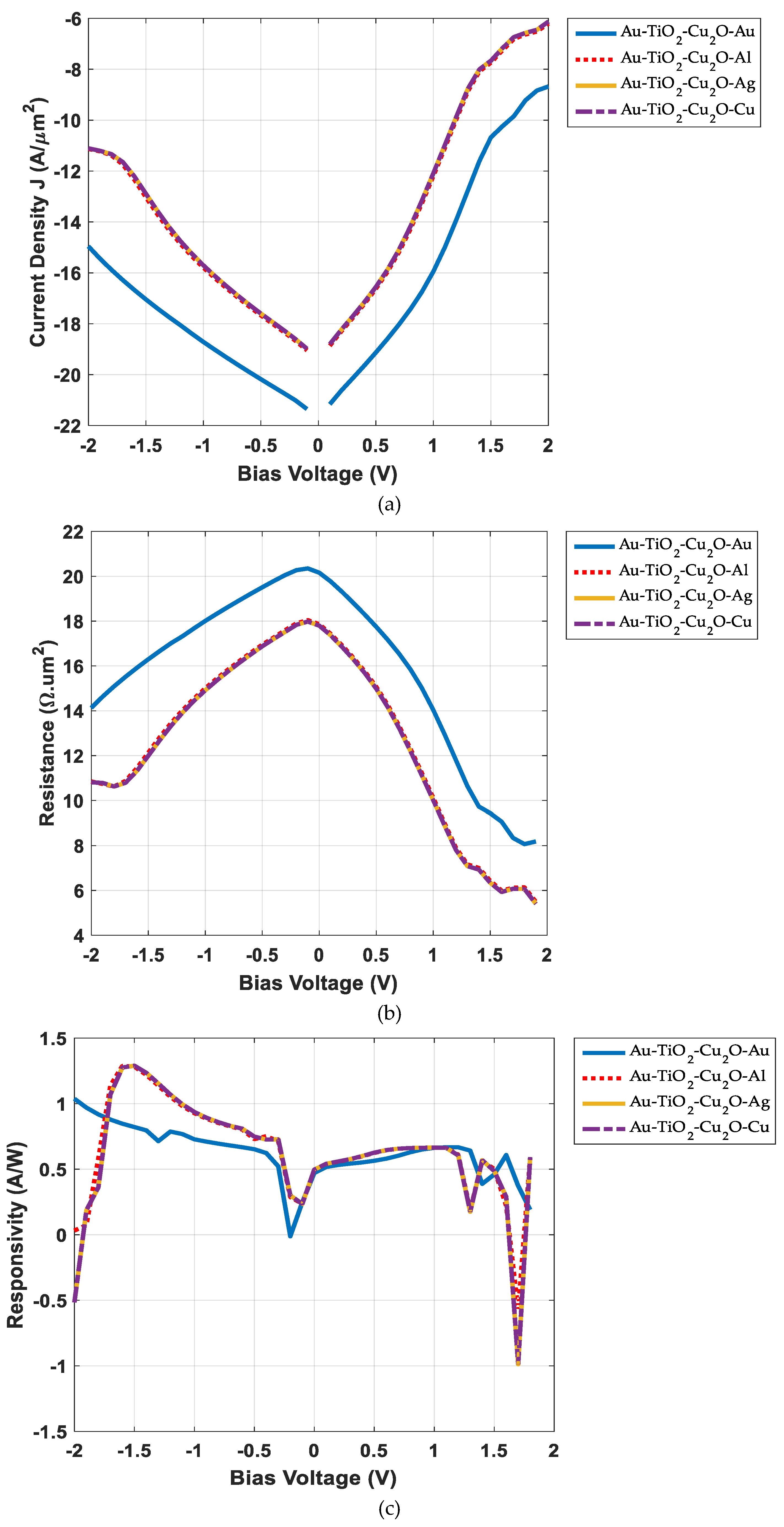
Figure 12 shows the comparison of I/V, R, and S characteristics of the M-TiO
2-Cu
2O-M rectenna. The changes in the insulator configuration vary the dielectric constant and electron affinity of materials that impact the rectenna characterization as can be noted easily by comparing the
Figure 11 and
Figure 12 curves. The insertion of titanium oxide and copper oxide between the spiral antenna feeding point produces the peak current densities of -8.67 dB A/µm
2 (Au--Au), -6.2 dB A/µm
2 (Au--Al), -6.12 dB A/µm
2 (Au--Ag), and -6.12 dB A/µm
2(Au--Cu).
The comparison reflects that for all figures of merits, the best and worst results are noticed for the insulator pairs of Al
2O
3 – Cu
2O and Al
2O
3 – TiO
2 respectively. Also, the asymmetric configuration of Au-Al2O3-Cu2O-Cu shows superior characteristics among all compared configurations. The lesser difference of bandgap and electron affinities of used metals and insulators (see
Table 2 [
33,
34,
35,
36]) for the symmetric metals case i.e. Au-Al2O3-Cu2O-Au configuration makes it less efficient. It has been proven in [
1,
14,
17,
37] that the asymmetric MIIM configurations with different metal electrodes perform better than symmetric configurations because of the difference in their band gap and electron affinities.
The reason for the best overall performance of Al
2O
3 – Cu
2O and TiO
2 - Cu
2O as insulator pairs in MIIM configurations is the lesser difference in their electron affinities as depicted in
Table 2. Also, both aluminum oxide and titanium oxide have high dielectric constant and low loss tangent, and their combination with copper oxide as an insulator increases the rectenna efficiency which produces the best field enhancement characteristics with these insulator pairs. This can also be confirmed by comparing the electric field distributions in
Figure 6 and
Figure 10.
The analysis reflects that both aluminum oxide and titanium oxide are good options with the pairing copper oxide as the insulators in MIIM rectenna at THz frequencies for IR energy harvesting. Although the rectification characteristics of both Al2O3 – Cu2O and TiO2 - Cu2O are similar, the preference could be given to Al2O3 – Cu2O pair as aluminum oxide is much cheaper than titanium oxide. Although titanium oxide has a higher dielectric constant (better rectenna efficiency) than aluminum oxide but is more expensive than aluminum oxide. The high availability of aluminum oxide at a lower cost makes it the better choice for the fabrication of the efficient MIIM rectenna for IR energy harvesting at 28.3 THz. The findings of this study can also be used for the analysis and realization of array configuration of the MIIM rectennas with best-performing metals and insulators for the increase in the rectified harvesting power.
