Preprint
Article

The Influence of TiO2 Nanoparticles Morphologies on the Performance of Lithium-Ion Batteries

Altmetrics

Downloads

92

Views

31

Comments

0

A peer-reviewed article of this preprint also exists.

Submitted:

16 August 2023

Posted:

17 August 2023

You are already at the latest version

Alerts
Abstract
Anode materials based on TiO2 nanoparticles of different morphologies were prepared using the hydrothermal method and characterized by various techniques, such as X-ray diffraction (DRX), scanning electron microscopy (FE-SEM), and N2 absorption. The TiO2 nanoparticles prepared were used as anode materials for lithium-ion batteries (LIBs), and their electrochemical properties were tested using discharging/charging measurements. The results showed that the initial morphology of the nanoparticles plays a minor role in battery performance after the first few cycles and that better capacity was achieved for TiO2 nanobelt morphology. The sharp drop in the specific capacity of LIB during their first cycles is examined considering changes in the morphology of TiO2 particles and their porosity properties in terms of shape and connectivity.
Keywords: 
Subject: Chemistry and Materials Science  -   Nanotechnology

1. Introduction

Renewable energies are increasingly becoming an alternative solution for overcoming the problems of fossil fuel pollution and meeting the growing demand for energy from human activity. However, to overcome the problem of intermittency, which limits their use when needed, renewable energy storage systems are currently emerging as credible and effective solutions. This concern has motivated the development of various storage systems, such as batteries [1,2] and supercapacitors [3,4]. Among these energy storage technologies, batteries appear to be the most promising.
Today, of all secondary batteries, lithium-ion batteries (LIBs) are the most widely used technology and have attracted a great deal of attention from the scientific community. This is due to their excellent performance, such as compactness, high-power, high-energy density, and high cycling capacity. LIBs are the most widely used secondary batteries as energy sources in portable technologies and electric vehicles [5,6] and as energy storage systems in solar and wind power plants [7]. Research into overcoming the difficulties associated with the limitations of LIBs and improving their performance is a hot topic in materials science. Although some limitations have been overcome, others are still being researched. Recent progress has focused on the preparation of innovative anode materials with optimized properties, which help to maintain the battery's capacity during its cycle. It is well known that electrode materials play a major role in determining battery efficiency. The main drawback of anode materials is that their volume expands and contracts during the battery cycle, which can lead to cracking of the anode materials. This can lead to a drastic reduction in capacity, as well as the battery exploding due to the overcharging [8,9].
Various strategies have been reported to overcome the reduction in anode volume expansion, including a better choice of material composition and/or architecture. In terms of material composition, TiO2 polymorphs have been used for LIB applications and have been shown to exhibit a small volume change, less than 4%, during Li+ lithiation/delithiation (insertion/extraction) [10,11]. TiO2 polymorphs have other advantages that make them an ideal candidate for LIB applications, such as high mechanical and chemical stability, environmental friendliness, low cost, high cyclability, a relatively high theoretical capacity of 335 mA h g-1 (anatase phase), and a flat operating potential (more than 1.7 V versus Li+/Li) [12,13]. The theoretical capacity of TiO2 is never reached due to various phenomena occurring during the LIB cycle. In fact, in most of the results reported in the literature, the capacity drops drastically after the first few cycles, and this is due both to the formation of a solid electrolyte interphase (SEI) layer on the surface of the anode materials resulting from the reaction of the electrolyte with the anode surface and to the disintegration of the anode material due to the stress induced by its volume variation during LIB cycles. To maintain a higher capacity and ensure longer reversible charge and discharge cycles, it is important to solve these problems. Identifying the morphology and architecture of materials that could accommodate the variation in anode volume and, consequently, reduce the stresses experienced by the materials during battery cycling, is of paramount importance in solving this problem. The aggregation of nanoparticles has proved to be a promising approach for obtaining materials with the desired architecture to attenuate the volume variation during LIB charge/discharge cycles [14]. Assemblies of nanoparticles of different sizes offer numerous possibilities for tailoring the porosity of agglomerated materials, in terms of pore size and morphology [15,16]. In addition, nanoparticle assemblies give rise to several cases of pore connectivity [17]. This type of material architecture is more flexible, making it possible to combine several material properties, even if they are of a conflicting nature [15]. For LIB application, the porous materials and particularly aggregate of nanoparticles offer the possibility to accommodate the structural stress of the anode material, induced by lithium insertion, which improves the stability of LIB recycling [16,18]. In addition, the agglomerated porous material offers a high interface surface area in contact with the electrolyte, which greatly reduces the diffusion pathways of Li+ ions into the material lattice [16,18].
In the present work, TiO2 materials with micro- and nano- structures made by TiO2 nanoparticles of different morphologies, as building unit, have been prepared using the hydrothermal method. Furthermore, on the light of the LIBs literature and the present results, the capacity decreasing with the number of discharging and charging cycles was discussed in terms of the evolution of TiO2 nanoparticles morphology, and the properties of their assembly with the LIB cycles. TiO2 materials were used as a model system to explore the underlying mechanisms behind the capacity decreasing with the first charging and discharging cycles.

2. Materials and Methods

2.1. Synthesis of TiO2 nanoparticles and aggregates

The hydrothermal method was used to synthesize TiO2 nanoparticles in the form of urchins, nanotubes, and belts. TiO2 aggregates were used as precursors and prepared according to previously published protocols [19]. For nanoparticle synthesis, 0.5 g of TiO2 aggregate precursor powder was introduced into a Teflon-lined autoclave with a capacity of 23 ml. The autoclave was then filled with a 10 M NaOH solution to 80% of the autoclave's capacity. Depending on the desired morphology, the synthesis temperature was maintained at different temperatures of 100, 150 and 220°C with a heating rate of 2.5°C/min and synthesis times of 360, 180 and 15 min. The nanoparticle powders obtained were then subjected to washing and annealing protocols to obtain the final stage in these processes: sodium titanate. The latter product was washed several times with a dilute HCl solution to reach a pH of 1, then with distilled water to reach a pH of 7. At the final stage of the synthesis process, the powder obtained was dried in an oven overnight, then annealed in air at a temperature of 500°C for 30 minutes, at a heating rate of 5°C/min. All the chemicals used were of analytical grade and were used as purchased, without further purification. The water used was purified by the Milli Q system (Millipore, electrical resistivity 18.2 MΩ.cm).
Four powders were prepared with different morphologies depending on the synthesis temperature and time. The powders are named TiO2-NU-100°C (nanourchin-like nanoparticles prepared at a synthesis temperature of 100°C), TiO2-NU-150°C (nanourchin-like nanoparticles prepared at a synthesis temperature of 150°C), TiO2-NT-200°C (nanotube-like nanoparticles prepared at a synthesis temperature of 200°C and a synthesis time of 15 min) and TiO2-NT-200°C (nanobelt-like nanoparticles prepared at a synthesis temperature of 200°C and a synthesis time of 360 min).

2.2. Characterization of prepared TiO2 nanoparticles and aggregates

The morphological investigations of the prepared TiO2 nanoparticles and aggregates were achieved with a high-resolution Ultra 55 Zeiss FEG scanning electron microscope (FEGSEM) operating at an acceleration voltage of 10 kV.
The crystalline structure of TiO2 was determined by an X-ray diffractometer (Siemens D5000 XRD unit) in 2θ range from 20 to 80 by 0.07 s−1 increasing steps, operating at 40 KV accelerating voltage and 40 mA current using Cu Kα radiation source with λ= 1.5406 Å. The average TiO2 crystallite sizes were calculated using Scherer formula: (D = 0.9λ / Bcosθ), and the analysis of the full width at half maximum of the intense peak corresponding to (020) crystallographic plane.
Nitrogen adsorption-desorption isotherms were measured at liquid nitrogen temperature on a BelSorp Max apparatus. Before analysis, the samples were degassed at 120°C for 10 hours. The specific surface area (SBET) was evaluated using the Brunauer-Emmett-Teller (BET) method in the P/P° range of 0.05-0.25. The pore size distribution was determined from the desorption branch of the isotherm using the NLDFT method (cylindrical pores; oxide materials). The total pore volume was determined from the amount of N2 adsorbed up to P/P°=0.98.
The chemical compositions of all the samples were determined by the FEGSEM using a Princeton Gamme-Tech PGT, USA, spirit energy dispersive spectrometry EDS system.
The electrochemical tests were performed in Teflon Swagelok half-cells, where TiO2 composite was used as a working electrode and a Li metal foil (Sigma Aldrich) as a reference, and a counter electrode in a battery grade electrolyte having the composition: 1M LiPF6 ethylene carbonate, propylene carbonate and dimethyl carbonate (1:1:1, v/v/v) with 1%wt vinylene carbonate, purchased from Solvionic, (France). The TiO2 composite electrode was prepared using a mortar, from a mixture of prepared TiO2 active material (80 wt %), 7 wt % of mesoporous carbon, 7% of graphite powder, and 6 wt % of poly (tetrafluoroethylene) (PTFE). The prepared homogenous mixture is uniformly pressed onto a stainless-steel foil substrate with a pressure of 125 bar. Thirdly, this electrode was dried in the oven for the whole night at the temperature of 80℃. Glass microfiber filter (Grade GF/D (Whatman)) 0.67 mm thick, with a pore size of 2.7 um (GmF) was used as a separator. The Swagelok cells were assembled in the MBraun Glove Box (with H2O < 1 ppm and O2 < 1 ppm). Assembled batteries were galvanostatically cycled in the voltage range between 3 - 1.0 V vs Li/Li+ at a charge/discharge rate of C/10 (full charge or discharge in 10 h), using a VMP3 Biologic multi-channel potentiostat/galvanostat.

3. Results and discussion

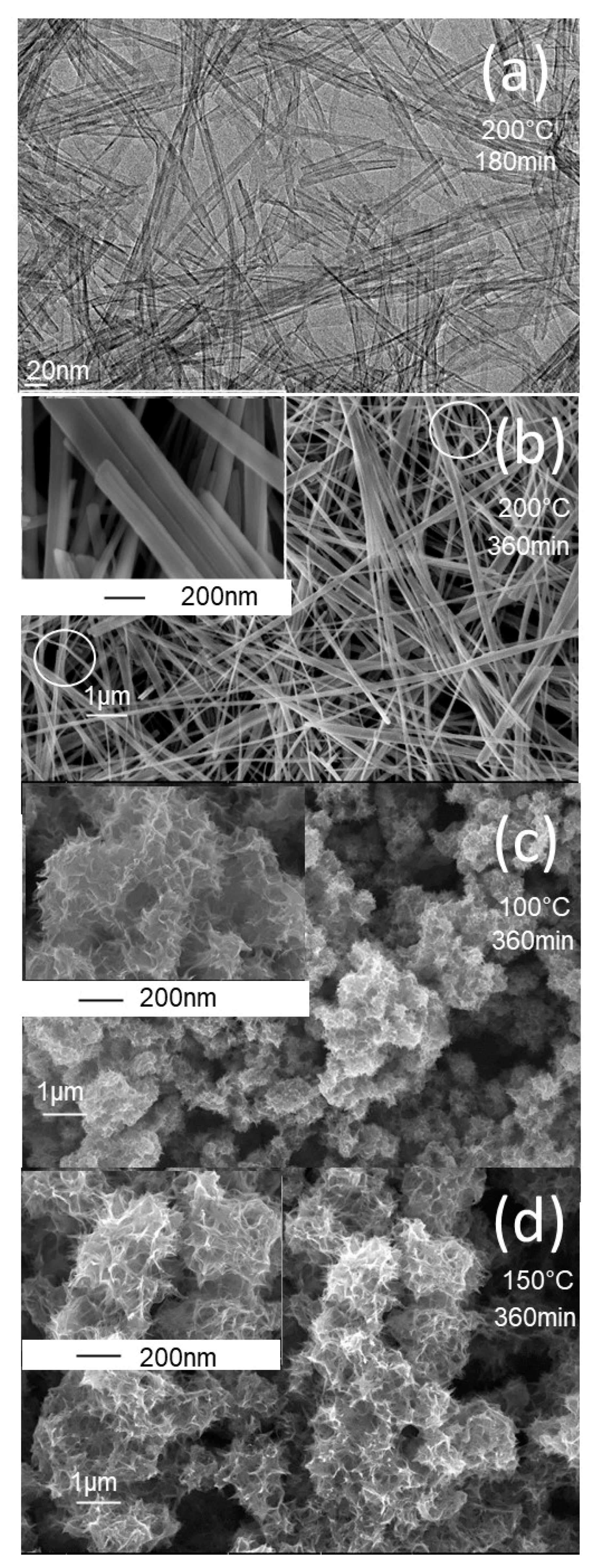
The synthesis protocols described in the experimental section yielded white powders that were characterized using a variety of techniques. The morphology of the prepared powders was characterized by FEGSEM, and the images obtained are shown in Figure 1. At a higher synthesis temperature of 200°C (Figure 1a,b), the TiO2 powder exhibits a nanotube morphology at a short synthesis time of 180 min, and a nanobelt morphology at a longer synthesis time of 360 min. The insert in Figure 1b shows a bundle of several nanobelts stacked along their longitudinal axis. It can also be seen that the nanobelts prepared have a homogeneous thickness of around 10 nm, a diameter ranging from 50 to 100 nm, and a length of more than 10 micrometers. At higher magnifications, the nanobelts have a smooth surface with no contamination. In addition, the regions shown in Figure 1b display curved nanobelts, illustrating their high elasticity. At the synthesis temperature of 100°C, the prepared powder has a sea-urchin-like morphology, with stretched sheets connected to form a randomly connected network (Figure 1c). At the synthesis temperature of 150°C, the morphology is like that obtained at a temperature of 150°C, but with more coiled sheets (Figure 1d).
The EDS spectrometry was used to analyze the chemical composition of prepared TiO2 powders, just after synthesis (Figure 2a) and after the washing and annealing steps (Figure 2b). The EDS spectra show the peak corresponding to Na just after synthesis Figure 2a, whereas after washing and annealing steps, the Na peak is completely absent (Figure 2b), which indicates the complete exchange of Na+ ions by H+ during the washing step.
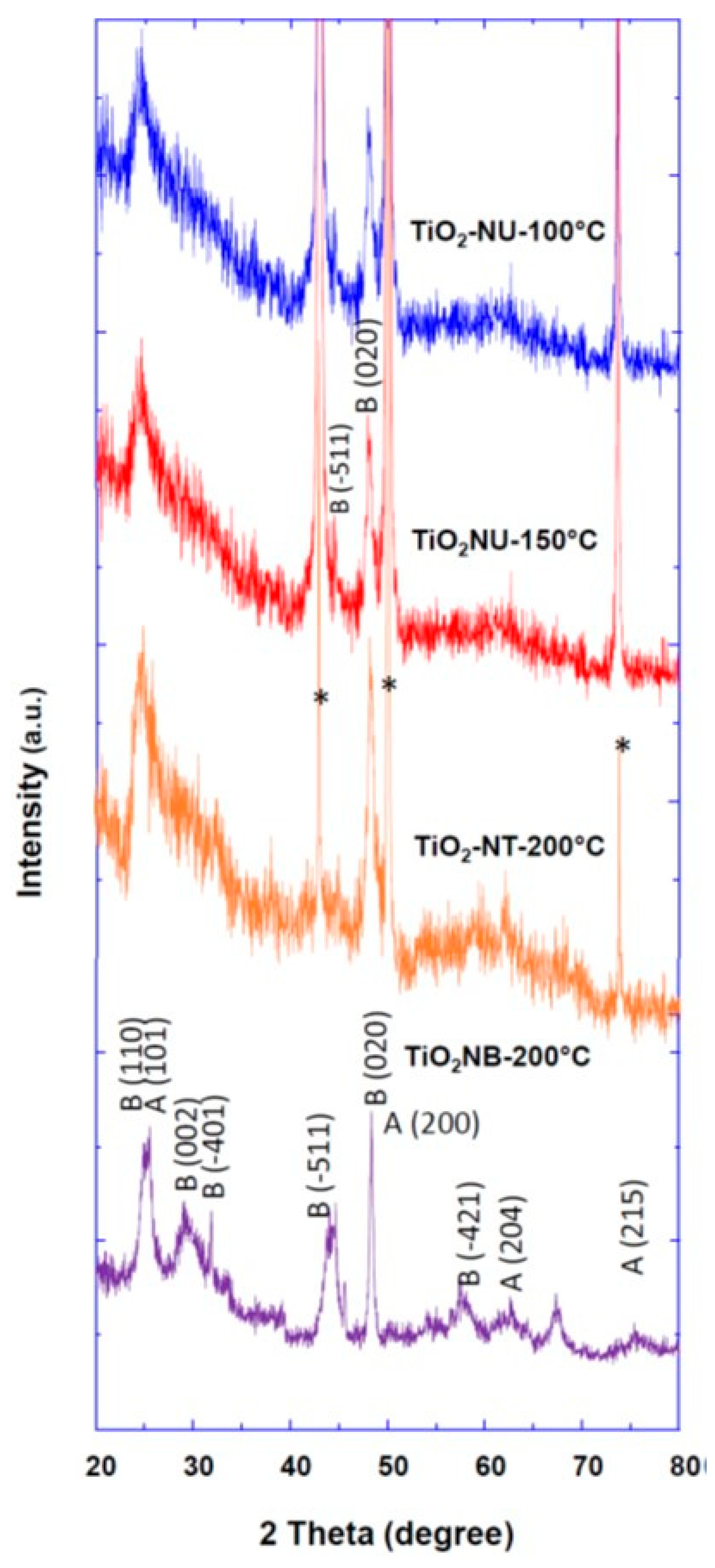
The crystalline structure and phase of prepared TiO2 powder with different morphologies were investigated by the XRD method, and the obtained patterns are depicted in Figure 3. In the case of TiO2 nanourchin and nanotube morphologies (TiO2-NT-200°C, TiO2-NU-150°C and TiO2-NU-100°C), well-pronounced peaks were observed and were assigned to (-511) and (020) crystallographic planes of pure TiO2 (B) phase (JCPDS No. 35-008) (Figure 3). In the case of TiO2 nanobelt morphology (TiO2-NB-200°C), the well-resolved XRD peaks were attributed to a mixture of anatase (JCPDS 83-2243) and brookite (JCPDS 29-1360) phases (Figure 3).
The properties of prepared TiO2 powders in terms of specific surface area, and the average pore size, were evaluated by analyzing the nitrogen adsorption-desorption isotherms. From the isotherm curves (Figure 4), the specific surface areas (BET model) were calculated to be 270 m2g−1, 329 m2g−1, 434 m2g−1 and 335 m2g−1, for respectively the TiO2 powder morphology of nanobelt (TiO2-NB-200°C), nanotube (TiO2-NT-200°C), nano-urchin((TiO2-NU-100°C), and (TiO2-NU-150°C). For most of the samples a multiscale porosity is observed: the smaller pores (2.5-3 nm) are likely due to the intrinsic porosity of the particles (porosity of the nanotube, nanobelt, or nanosheet), while the porosity leading to the second maximum in the pore size distribution (about 5 nm) is probably related to pores resulting from the aggregation of the primary particles. Lastly, the larger pores (between 10 and 20 nm) could result from the flexible porosity formed between particles that are not chemically linked. It is worth noting that the porosity of TiO2-NU-150°C is like that of TiO2-NT-200°C, which is consistent with the fact that the nanotube particles are obtained by nanosheets enrolling as reported previously [19]. It is commonly accepted that the large surface area enhances the material contact surface with the electrolyte, and the large pore size favors fast diffusion and transfer toward the material surface [5,16,18]. These characteristics favor the improvement of LIB rate capability.
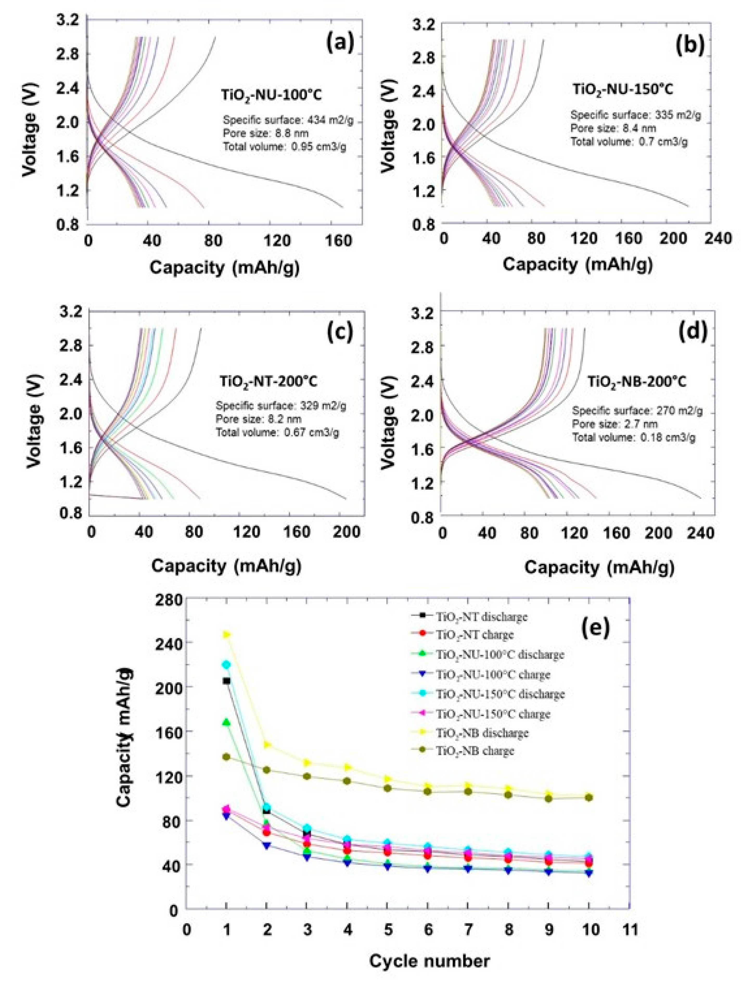
The electrochemical characterizations of prepared TiO2 powders with different morphologies were performed. The obtained discharging/charging curves at a current rate of C/10 are shown in Figure 5.
It can be observed that the specific capacity decreases as a function of the number of discharging/charging cycles (Figure 5e). At the first initial discharging process, the highest capacity of about 250 mAh/g was observed for the nanobelt morphology. For the other morphologies, this initial capacity was about 210 mAh/g, 170 mAh/g and 220 mAh/g for respectively the TiO2 powder morphologies of nanotube (TiO2-NT-200°C), and nanourchin (TiO2-NU-100°C and TiO2-NB-150°C). It is important to note that the specific capacities corresponding to the different morphologies are lower than the theoretical capacity of TiO2, which is approximately 336 mA h g-1. One could expect that higher capacities are associated to materials with a higher specific surface, which provide a higher contact surface area with the electrolyte. For example, it can be observed that TiO2 powders of nanotube and nanourchin-150 morphologies show similar specific capacity, which could be explained by their similar specific surface area. Moreover, TiO2 powder with nanourchin morphology shows more enrolled nanosheets (TiO2-NU-150°C) which resembles that of the nanotube morphology. However, the TiO2-NU-100°C powder has a higher specific surface than nanourchin-150 (434 vs 335 m2/g), and should, normally, exhibit a higher capacity. The electrochemical measurements show a lower capacity, which is very surprising, if only the specific surface parameter is considered. After the first discharging step, the specific capacity decreases very fast for all prepared TiO2 powder morphologies, and it reaches a plateau after a few numbers of discharging/charging cycles. To understand this behavior, another phenomenon of individual nanoparticles should be discussed to explain the observed variation of the specific capacity versus the number of discharging/charging cycles. It was reported that the anode material expansion and shrinkage during the lithiation/dilithiation induces the formation of cracks and the initial TiO2 particles disintegration into small nanoparticles. This in turn provokes the electric disconnection between the current collector and the anode materials. This lowers the LIB cycling stability and specific capacity [2]. Furthermore, the observed irreversible capacity during the first cycle could be explained mainly by the formation of the passivating layer named solid electrolyte interphase layer (SEI) on the electrode surface because of the electrolyte reduction [20,21,22], and the trapping of the inserted lithium in the crystal lattice defects or on the electrode surface sites [23]. This explains the low capacity observed than the theoretical calculated capacity which is equal to 335 mA h g-1 [12,24,25].
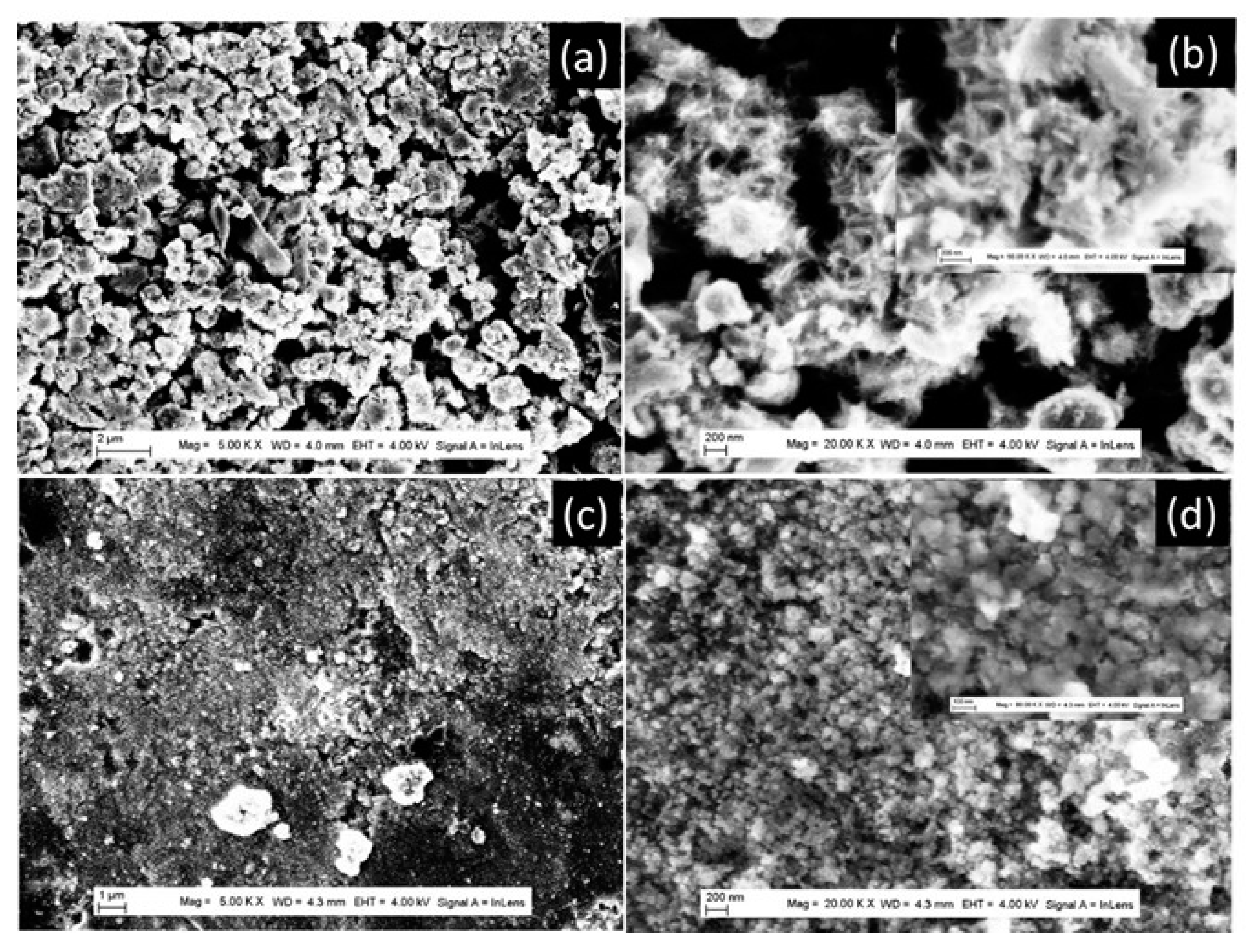
Hereafter, we will discuss how the control over the TiO2 powder morphology may be used to improve the Li-ion batteries' performance. It is well accepted that the pore properties (size and connectivity) and the specific surface depend on the prepared TiO2 powder morphology, and it plays a crucial role in the optimization of the Li-ion batteries' specific capacity [26]. To understand how these parameters are behind the observed decrease of the specific capacity, versus the discharging/charging cycles, we must investigate the evolution of the TiO2 powder morphology during the cycling process. To check this point, the FEGSEM characterization was performed just after the preparation of the anode for battery testing and after 10 discharging/charging cycles. The results are presented in Figure 6, Figure 7 and Figure 8, for prepared TiO2 powders with different morphologies. The TiO2-NU-100°C powder, with stretched nanosheets, starts to collapse during the preparation of the anode electrode (Figure 6a,b), inducing the decrease of the anode-specific surface. After the 10th discharging cycle, it can be observed that the nanosheets of nano-urchin morphology did mostly collapse, to form aggregates of around 100 nm diameter (Figure 6c,d). The observed peculiarity with the TiO2-NU-100°C powder, in terms of low specific capacity (Figure 5), despite that it is characterized by the highest specific surface just after synthesis, could be explained by the fact that the stretched sheet forming nano-urchin morphology is easy to collapse, during the battery’s fabrication process. After their preparation, the nanourchin morphology evolves to a denser structure with a lower specific surface than that of nanobelt morphology. Similar nanosheets collapse behavior was previously observed with TiO2 powders of nano-urchin morphology by Tian-Hui et al [27].
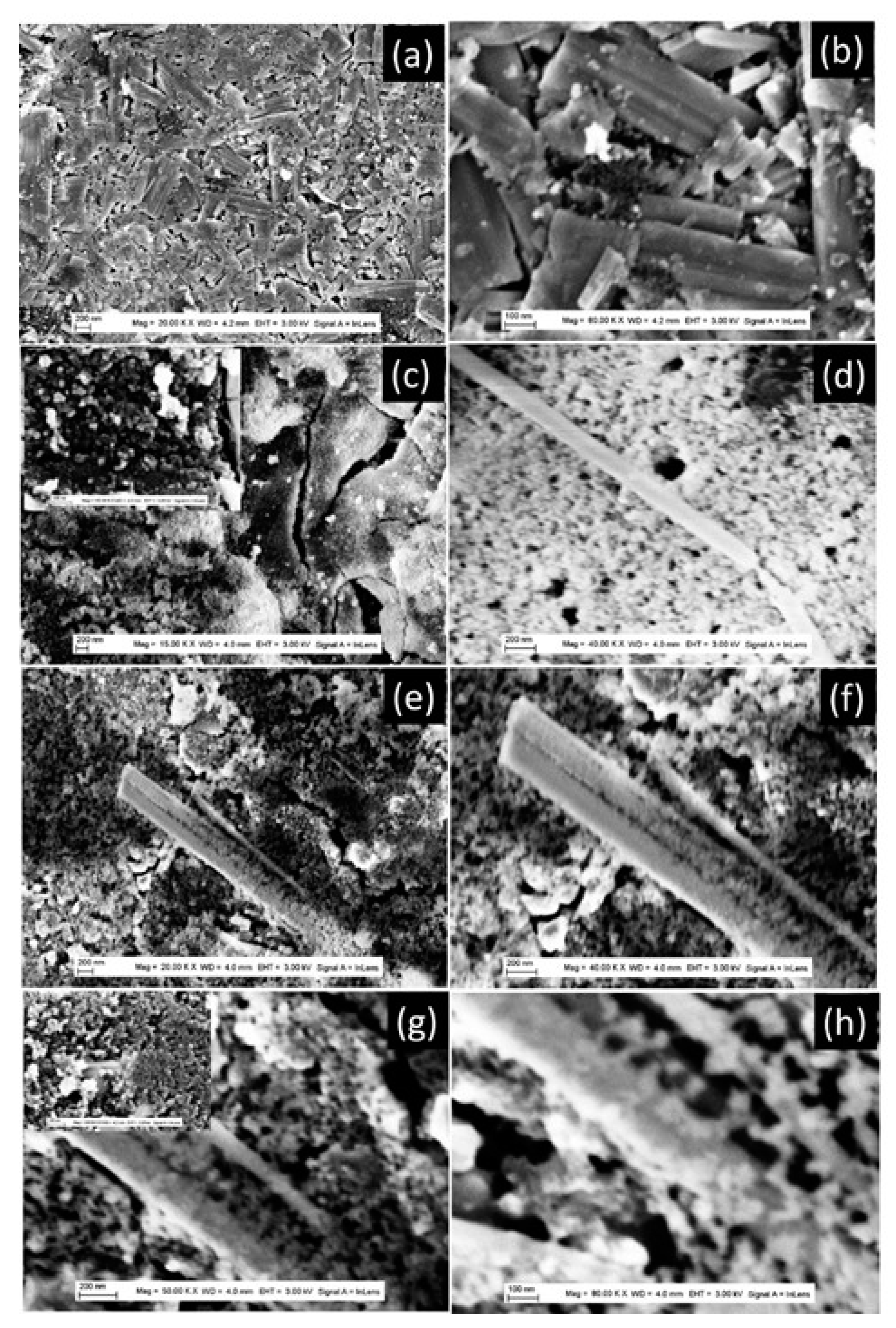
Similar behavior was observed with TiO2-NB-200°C powder, in terms of a strong decrease of the LIB-specific capacity between the first and the 10th discharging cycle (Figure 5). To understand this behavior in the case of nanobelt morphology, we analyzed closely the FEGSEM characterization before batteries testing, and after the 10th discharging cycle (Figure 8). Just after the preparation of the anode, the TiO2 powder keeps its nanobelt morphology as it can be identified in the FEGSEM pattern of Figure 7a,b. After the 10th cycle, only the aggregates with diameters ranging from 50 nm to 200 nm could be observed, in addition to a few nanobelts (Figure 7c–h). Further analysis of the FEGSEM images (Figure 7e–h) shows a belt-shaped nanoparticle that is in the process of disintegrating with a coexistence of a part of the particle that is transformed into particle aggregates and another that is not yet. This clearly shows that the aggregates observed are the result of the disintegration of the belt-shaped nanoparticles under the effect of the stress generated by the lithium-ion insertion/extraction process during the charge and discharge cycles. (Figure 7e–h). It is well known that lithium storage capacity in the anode material induces its expansion during the lithium insertion, which can provoke mechanical fracture in individual nanobelts, and its disintegration into aggregates.
With TiO2-NT-200°C powder, aggregates are formed during the battery’s fabrication process (Figure 8a,b). At high magnification in Figure 8b and the insert, TiO2 nanotubes could be observed. After the 10th cycle, cracks are formed (Figure 8c,d), and aggregates of nanotubes could be observed with diameter ranging from 20nm to 50nm (Figure 8e,f). Regarding, TiO2-NU-150°C powder, it collapses during the battery’s fabrication process but with less intensity than in the case of TiO2-NU-100°C. This is due to its nanosheet enrolled structure, which provides more resistance to the change of the powder’s morphology during the fabrication process. TiO2 nanotubes and their aggregation led to a reduction in surface area, which explains its lower capacity compared to that of nanobelt powder.
It is well known that nanoparticle aggregates are usually a porous materials characterized by pore size, size distribution, connectivity, and specific surface. Furthermore, it is well accepted that these parameters affect the Li-ion diffusion within the LIB electrode and are also behind the volume accommodation during the insertion/extraction cycle of Li-ion [2,16,18]. The obtained results are very surprising if we consider only the geometrical model in which the reduction of the pore size induces the enhancement of the specific surface, and in turn the specific capacity as previously observed by Lin et al [14].
In addition, the pore's connectivity should play an important role in the optimization of energy storage of porous electrodes [28]. However, during the first discharging cycle, the TiO2 powders are keeping different morphologies and probably different connectivity, which could also explain the observed difference in specific capacities for all the TiO2 powders, in addition to their specific surface. The small variation in capacity in the form of plateaus observed in Figure 5e can be explained by the fact that, for all the samples except the nanobelt nanoparticles, the shapes, sizes, and connectivity of the pores are the same for the disintegrated nanoparticles after 10 charge/discharge cycles. In addition, this very small variation in the specific capacity is the signature of a reversible charge/discharge process. This could be explained by the architecture of the anode materials in terms of the pore properties (size, shape, and connectivity), which successfully mitigate the impact of the variation in anode volume on capacity during charge/discharge cycles.
These results were confirmed by XRD experiments (Table 1), which show that the crystallite size decreases between the 1st and the 10th cycle. This confirms that during the discharging/charging cycles, large particles were disintegrated into small ones. Furthermore, by comparing the crystallite size after the 10th cycle, we note that the nanobelt morphology shows small crystallite, which should have a high specific surface, explaining the corresponding high specific capacity. In addition, the other morphologies show more or less the same crystallite size, which explains their closer specific capacity. These results also confirm that the size of nanoparticles after the same number of LIB charge-discharge cycles depends on the properties of the powders used as active electrode materials, such as morphology, size, crystallinity, and the nature of the phases.
4. Conclusions

The large variation of the LIB capacity between the first and the 10th cycle was demonstrated to be attributed to the morphology evolution during the battery’s preparation process and the first discharging/charging cycles, which prone that the pores size and connectivity play a major influence on the LIB capacity. This in addition to the formation of cracks, because of volume expansion during the LIB discharging/charging cycles, which provokes the disintegration of individual particles into aggregates of smaller crystallites. Furthermore, the observed plateau in the capacity versus the number of discharging/charging cycles was attributed to the properties of formed aggregates in terms of pores size, specific surface, and their capability to accommodate the volume variation and ensure reversibility of charging and discharging processes of the LIB. It has been shown that aggregates with a small crystallite size have a higher capacity with a small decrease as a function of the number of cycles, indicating better reversibility of the LIB discharge/charge processes. Furthermore, controlling the pore characteristics of porous materials is a key issue to better accommodate the anode volume variation for improving LIBs performance.
These results will make a significant contribution to the understanding of the cyclability of LIBs and the variation of their specific capacity during early discharging/charging cycles, bringing new thinking to the design of the best electrode material architectures for improved LIBs performance.

Author Contributions

Conceptualization, A.T.; methodology, A.T.; validation, A.T., formal analysis, A.T.; J.B.; W.L.; Y.X.; investigation, W.L.; J. B.; resources, A.T.; data curation, W. L.; J. B.; writing—original draft preparation, A. T.; W.L.; writing—review and editing, A.T.; J. B.; Y. X.; supervision, A.T.; project administration, A.T.; funding acquisition, A.T.; All authors have read and agreed to the published version of the manuscript.

Funding

This research was funded by the European Union′s Horizon 2020 research and innovation program under the Marie Sklodowska-Curie grant agreement No 734276.

Data Availability Statement

The data presented in this study are available on request from the corresponding author.

Acknowledgements

The authors would like also to thank the Chinese Scholar Council for supporting Wenpo Luo with a scholarship.

Conflicts of Interest

The authors declare no conflict of interest. The funders had no role in the design of the study; in the collection, analyses, or interpretation of data; in the writing of the manuscript, or in the decision to publish the results.

References

  1. Qu, J.; Ding, J.; Yuan, N. The synthesis of four morphologies of TiO2 through temperature control and their electrochemical performance, Int. J. Elecrochem. Sci. 2015, 10, 8385–8394. [Google Scholar] [CrossRef]
  2. Lu, J.; Chen, Z.; Pan, F.; Cui, Y.; Amine, K. High-Performance anode materials for rechargeable lithium-ion batteries, Electrochem. Energy R. 2018, 1, 35–53. [Google Scholar] [CrossRef]
  3. Zhao, Z.; Tian, J.; Sang, Y.; Cabot, A.; Liu, H. Structure, synthesis, and applications of TiO2 nanobelts, Adv. Mater. 2015, 27, 2557–582. [Google Scholar] [CrossRef]
  4. Xiang, C.; Li, M.; Zhi, M.; Manivannan, A. ; Wu, N Reduced graphene oxide/titanium dioxide composites for supercapacitor electrodes: shape and coupling effects J. Mater. Chem. 2012, 22, 19161. [Google Scholar] [CrossRef]
  5. Tarascon, J. M.; Armand, M. Issues and challenges facing rechargeable lithium batteries. Nature 2001, 41, 359–367. [Google Scholar] [CrossRef] [PubMed]
  6. Scrosati, B. ; Challenge of portable power, Nature 1995, 373, 557–558. [CrossRef]
  7. Liu, Y.; Wu, X.; Du, J.; Song, Z.; Wu, G. Optimal sizing of wind-energy storage system considering battery life, Renew. Energy 2020, 147, 247–2483. [Google Scholar] [CrossRef]
  8. Yazami, R. Surface chemistry and lithium storage capability of the graphite lithium electrode. Electrochem. Acta 1999, 45, 87–97. [Google Scholar] [CrossRef]
  9. Pupus, A.; Varna, J. modeling mechanical stress and exfoliation damage in carbon fiber electrodes subjected to cyclic intercalation/deintercalation of lithium ions. Comp Part B 2014, 65, 69–79. [Google Scholar] [CrossRef]
  10. Li, X.; Zhang, X.; Li, T.; Zhong, Q.; Li, H.; Huang, J. Graphene nanoscrolls encapsulated TiO2 nanowires for lithium storage. J. Power Sources 2014, 268, 372–378. [Google Scholar] [CrossRef]
  11. Jin, J.; Huang, S. Z.; Liu, J. , Design of new anode materials based on hierarchical three-dimensional ordered macro mesoporous TiO2 for high performance lithium-ion batteries, J. Mater. Chem. A, 2014, 2, 9699–9708. [Google Scholar] [CrossRef]
  12. Ming, H.; Yan, Y.; Ming, J.; Li, X.; Zhou, G.; Huang, H.; Zheng, J. Porous TiO2 nanoribbons and TiO2 nanoribbon/carbon dot composites for enhanced Li-ion storage. RSC Adv. 2014, 4, 12971. [Google Scholar] [CrossRef]
  13. Deng, D.; Kim, M.; Lee, J. Y.; Cho, J. Green energy storage materials: Nanostructured TiO2 and Sn-based anodes for lithium-ion batteries, Energ. environ. Sci. 2009, 2, 818. [Google Scholar] [CrossRef]
  14. Lin, Z.; Zheng, M.; Zhao, B.; Wang, G.; Pu, L.; Shi, Y. Influence of the pore structure parameters of mesoporous anatase microsphereson their performance in Lithium-ion batteries. J. Solid state Electrochem 2014, 18, 1673–1681. [Google Scholar] [CrossRef]
  15. Taleb, A.; Mesguich, F.; Hérissan, A.; Colbeau-Justin, C.; Xue, Y.; Dubot, P. Optimized TiO2 nanoparticle packing for DSSC photovoltaic applications. Solar Energy Materials & Solar Cells 2016, 148, 52–59. [Google Scholar] [CrossRef]
  16. Luo, W.; Blanchard, J.; Tonelli, D.; Taleb, A. Synthesis of TiO2 Nanobelt Bundles Decorated with TiO2 Nanoparticles and Aggregates and Their Use as Anode Materials for Lithium-Ion Batteries. Micromachines 2023, 14, 243. [Google Scholar] [CrossRef] [PubMed]
  17. Vasilyev, O. A.; Kornyshev, A. A.; Kondrat, S. Connections Matter: On the importance of pore percolation for nanoporous supercapacitors, ACS Appl. Energy Mater. 2019, 2, 5386–5390. [Google Scholar] [CrossRef]
  18. Vu, A.; Qian, Y.; Stein, A. Porous Electrode Materials for Lithium-Ion Batteries-How to Prepare Them and What Makes Them Special. Adv. Energy Mater. 2012, 2, 1056–1085. [Google Scholar] [CrossRef]
  19. Luo, W.; Taleb, A. Large-Scale Synthesis Route of TiO2 Nanomaterials with Controlled Morphologies Using Hydrothermal Method and TiO2 Aggregates as Precursor. Nanomaterials 2021, 11, 365. [Google Scholar] [CrossRef] [PubMed]
  20. Lee, K.H.; Song, S.W. One-step hydrothermal synthesis of mesoporous anatase TiO2 microsphere and interfacial control for enhanced lithium storage performance. ACS Appl. Mater. Interfaces 2011, 3, 3697–3703. [Google Scholar] [CrossRef]
  21. Dongqing Liu, Qipeng Yu, Shuai Liu, Kun Qian, Shuwei Wang, Wei Sun, Xiao-Qing Yang, Feiyu Kang, Baohua Li, Evolution of Solid Electrolyte Interface on TiO2 Electrodes in an Aqueous Li-Ion Battery Studied Using Scanning Electrochemical Microscopy. J. Phys. Chem. C, 2019, 20, 12797–12806. [CrossRef]
  22. Wang, A.; Kadam, S.; Li, H.; Shi, S.; Qi, Y. Review on modeling of the anode solid electrolyte interphase (SEI) for lithium-ion batteries. npj Computational Materials 2018, 4, 15. [Google Scholar] [CrossRef]
  23. Kang, J.W.; Kim, D.H.; Mathew, V.; Lim, J.S.; Gim, J.H.; Kim, J. Particle size effect of anatase TiO2 nanocrystals for lithium-ion batteries. J. Electrochem. Soc. 2011, 158, A59–A62. [Google Scholar] [CrossRef]
  24. Sourav, P.; Md. Arafat, R.; Md. Saiful, I.; Md. Rasidul, I.; Safina-E-Tahura S. Nanostructured anatase TiO2 as anode of high performance lithium-ion batteries. Battery Energy. 2022, 1, 20220018. [CrossRef]
  25. Liang, S.; Wang, X.; Qi, R.; Cheng, Y-J.; Xia, Y.; Müller-Buschbaum, P.; Hu, X. Bronze-Phase TiO2 as Anode Materials in Lithium and Sodium-Ion Batteries. Adv. Fun. Mater. 2022, 32, 2201675. [CrossRef]
  26. Mehraz, S.; Luo, W.; Swiatowska, J.; Bezzazi, B.; Taleb, A. Hydrothermal Synthesis of TiO2 Aggregates and Their Applications as Negative Electrodes for Lithium-ion Batteries: The Conflicting Effects of Specific Surface and Pore Size. Materials 2021, 14, 916. [Google Scholar] [CrossRef] [PubMed]
  27. Tian-Hui, Z.; Ling-Yu, P.; Su-ling, Z.; Zheng, X.; Qian, W.; Chao, K. application of TiO2 with different structures in soar cells. Chin. Phys. B 2012, 21, 118401. [Google Scholar] [CrossRef]
  28. Lin, Z.; Yue, W.; Huang, D.; Hu, J.; Zhang, X.; Yuan, Z.; Yang, X. Pore length control of mesoporous Co3O4 and its influence on the capacity of porous electrodes for lithium-ion batteries. RSC Adv. 2012, 2, 1794–1797. [Google Scholar] [CrossRef]
Figure 1. FEGSEM and TEM images of TiO2 powder of different morphologies prepared at different synthesis times and temperatures. (a) TEM image of TiO2-NT-200°C powder prepared at synthesis temperature of 200°C, over 180min, (b) FEGSEM image of TiO2-NB-200°C powder prepared at synthesis temperature of 200°C over 360min, (c) FEGSEM image of TIO2-NU-100°C powder prepared at synthesis temperature of 100°C, over 360min and (d) FEGSEM image of TiO2-NU-150°C powder prepared at synthesis temperature of 150°C, over 360min. the inserts are the corresponding high magnifications.
Preprints 82534 g001
Figure 2. EDS spectrum images of prepared TiO2 powders (a) just after synthesis and (b) after washing and annealing processes.
Preprints 82534 g002
Figure 3. XRD pattern of TiO2 powders with different morphologies prepared at different synthesis temperatures as indicated. The peaks with stars correspond to the substrate.
Preprints 82534 g003
Figure 4. (a): N2 physisorption isotherm of TiO2 powders with different morphologies as indicated; (b): the corresponding pore size distribution (NLDFT).
Preprints 82534 g004
Figure 5. the potential-capacity curves corresponding to discharge/charge cycles of the first 10 cycles for different TiO2 powder morphologies (a-d), The curves of specific capacity versus the number of charge/discharge cycles for different TiO2 powder morphologies (e).
Preprints 82534 g005
Figure 6. FEGSEM images of TiO2 powder with nano-urchin100 morphology (a) and (b) different magnifications of the anode materials after preparation (c) and (d) different magnifications de anode materials after 10 discharging/charging cycles. The inserts are the corresponding high magnification.
Preprints 82534 g006
Figure 7. FEGSEM images of TiO2 powder with nanobelt morphology (a) and (b) different magnifications of the anode materials after preparation (c)-(h) different magnifications de anode materials after 10 discharging/charging cycles. The inserts are the corresponding high or low magnification.
Preprints 82534 g007
Figure 8. FEGSEM images of TiO2 powder with nanotube morphology (a) and (b) different magnifications of the anode materials after preparation (c) - (f) different magnification de anode materials after 10th discharging/charging cycles. The inserts are the corresponding high magnification.
Preprints 82534 g008
Table 1. Crystallite sizes (nm) of TiO2 powders after preparation of the anode electrode and after 10 discharging/charging cycles.
Preprints 82534 i001
Disclaimer/Publisher’s Note: The statements, opinions and data contained in all publications are solely those of the individual author(s) and contributor(s) and not of MDPI and/or the editor(s). MDPI and/or the editor(s) disclaim responsibility for any injury to people or property resulting from any ideas, methods, instructions or products referred to in the content.
Copyright: This open access article is published under a Creative Commons CC BY 4.0 license, which permit the free download, distribution, and reuse, provided that the author and preprint are cited in any reuse.
Prerpints.org logo

Preprints.org is a free preprint server supported by MDPI in Basel, Switzerland.

Subscribe

© 2024 MDPI (Basel, Switzerland) unless otherwise stated