Submitted:
17 August 2023
Posted:
18 August 2023
You are already at the latest version
Abstract
During the development of horizontal wells in bottom water reservoirs, the strong heterogeneity of reservoir permeability leads to premature bottom water breakthrough at locations with high permeability in the horizontal wellbore, and the water content rises rapidly, which seriously affects production. In order to cope with this problem, a new technology has emerged in recent years that utilizes gravel filling to block the flow in the annulus between the horizontal well and the borehole, and utilizes the Inflow Control Device (ICD) completion tool to carry out segmental water control in horizontal wells. Unlike conventional horizontal well ICD completions that use packers for segmentation, gravel pack combined with ICD completions breaks the original seg-mentation routine and increases the complexity of production dynamic simulation. In this paper, the flow in different spatial dimensions such as reservoir, gravel packed layer, ICD completion section and horizontal wellbore is modeled separately, and the annular pressure at different locations is used as the solution variable for the coupled solution, which realizes the prediction of oil production, water production and water content of gravel pack combined with ICD completions of horizontal wells. The model was used to calculate the effects of different crude oil viscosities, different reservoir permeabilities, different permeabilities of gravel packed layers, and different development stages on the water control effects of gravel pack combined ICD completions and conventional ICD completions at field conditions. This study provides a basis for using gravel pack combined ICD completions in horizontal wells in bottom water reservoirs.
Keywords:
inflow control device
; horizontal wells
; bottom water reservoir
; gravel pack
1. Introduction
In light of recent strides in drilling and completion technologies, horizontal wells have emerged as the predominant well configuration employed for the exploitation of bottom water reservoirs [1]. The elongation of horizontal well trajectories augments the interfacial expanse connecting the wellbore and the reservoir, thereby amplifying well productivity. However, concomitant with these enhancements, a suite of challenges emerges. Primarily, the protracted wellbore length engenders friction-induced pressure differentials within the horizontal conduit. Consequently, a discernible pressure deficit manifests at the "heel" segment relative to the "toe" counterpart, engendering disparately distributed inflow along the wellbore trajectory. Secondarily, the reservoir's inherent heterogeneity bestows non-uniform fluid influx longitudinally within the horizontal wellbore, hastening premature incursion of bottom water. This influx disparity precipitates escalated aqueous encroachment, thereby engendering elevated aqueous content and a precipitous diminution in oil production rates [2].
1.1. ICD Types
To address this quandary, the adoption of inflow control devices (ICDs) is progressively gaining traction within horizontal wells situated in bottom water reservoirs, offering a singular pathway toward attaining precision control and optimization of subsurface hydrodynamics within an individual well or reservoir milieu. The underlying premise of effectuating an ICD completion resides in the endeavor to orchestrate uniformity in inflow traversing the longitudinal expanse of the horizontal wellbore, a feat facilitated through the judicious application of the choke phenomenon intrinsic to the ICD apparatus, thereby ameliorating the manifestations stemming from the oscillations between the "heel" and "toe" and permeability gradients [3]. It is imperative to underscore that the deployment of ICDs necessitates meticulous consideration of inaugural reservoir parameters and assumes an immutability post-installation, precluding any subsequent adjustments or replacements.
Diverse variants of inflow control devices (ICDs) exist, each predicated upon distinct mechanisms to induce the requisite pressure decrement concomitant with fluid flow. Among these, the prevailing archetypes encompass the channel and nozzle configurations, prominently featured as the two principal categories. While nuanced discrepancies in design characterize these divergent ICD types, it remains salient to underscore that their underlying operational tenets converge upon a shared foundational principle [4].
The channel-type inflow control device (ICD) stands as an inaugural manifestation within the pantheon of ICD categories, characterized by the utilization of distinct channel lengths to modulate fluid dynamics [5]. Fundamentally rooted in its design, the channel-type ICD harnesses an extended conduit, thereby engendering an augmented pressure differential consequent to fluid traversal. This orchestrated pressure dichotomy engenders a correspondingly subdued flow velocity, thereby mitigating the propensity for erosive and obstructive events. Nonetheless, concomitantly, in scenarios typified by heightened oil-water viscosity ratios, the emergent frictional interactions furnish a pronounced pressure differential variance, as visually depicted in Figure 1.
The nozzle-type inflow control device (ICD) constitutes an alternative category, characterized by the employment of diminutive nozzles or orifices to effectuate a targeted pressure descent [6]. In stark contradistinction to the channel-type ICD archetype, the nozzle-type variant pivots upon the dynamic interplay of fluid density and velocity, rather than being predominantly contingent upon viscosity. This design paradigm, notable for its conceptual simplicity and malleability, accommodates facile reconfiguration. However, it also manifests heightened vulnerability to abrasion stemming from sand particulates.
In addition, an array of alternative ICD typologies augments the landscape, encompassing the nozzle-channel hybrid ICD, labyrinthine iterations, among others [7].
1.2. Horizontal Well Gravel Pack
Gravel packing constitutes a strategic completion methodology harnessed for the management of formation sand mobilization within unobstructed wellbores. This technique entails the emplacement of a screen encircling the perforated base pipe, succeeded by the injection of high-permeability gravel into the wellbore, executed through a recirculatory modality. This procedural configuration engenders the meticulous occupation of the interstitial zone between the screen and the reservoir formation, culminating in the establishment of a resilient subterranean milieu, characterized by sustained fluid production devoid of entrained formation sand. The assimilation of gravel-packing technology within conventional oil wells has reached a state of pronounced maturity, progressively extending its purview to horizontal well configurations within bottom water reservoirs [8]. Antecedently, early endeavors in horizontal well sand management entailed the integration of prepacked screens within unobstructed wellbores, thereby orchestrating sand production control. However, the efficacy of this approach was swiftly overshadowed by mounting challenges, as evinced by a disconcerting failure incidence, peaking at 25% for prepacked screen completions in the Gulf of Mexico [9]. Subsequent contemplation precipitated the realization that an open hole gravel packing regimen engenders an efficacious conduit toward enhancing the dependability, efficacy, and enduring viability of horizontal well sand control [10].In preliminary forays aimed at imbuing horizontal wells with gravel packing, the density-balancing paradigm was embraced to counteract the adversarial influences of gravity. Alas, the outcome was met with limited success [11]. Thereupon, the alpha/beta wave methodology emerged as a pervasive and efficacious approach, extensively deployed to effectuate gravel packing across a diverse spectrum of horizontal wells, reaping augmented triumph. This methodology effectually curtails the risk of erosive manifestations, concurrently augmenting the tractability of the circulation pathway, attributed to a continuum of enhancements iteratively infused into the constituent tool architecture [12].
The amalgamation of gravel pack and inflow control device (ICD) completion embodies a synergistic fusion of gravel packing technology and the ICD completion strategy. This composite approach entails the deposition of gravel materials within the annular interstice that resides between the ICD completion tubing and the circumferential borehole wall. The resultant configuration engenders an axial confinement, effecting a circumferential seal within the annular void. This seal exerts a localized impediment upon the ingress of influxing fluids across discrete well segments. Functionally akin to the deployment of multiple packers, this integrated methodology assumes a multifaceted role, prominently encompassing the attenuation of inflow emanating from high-permeability strata. Additionally, it assumes the mantle of a selective flow regulator, culminating in the attainment of a dualistic objective: controlling water encroachment while concurrently augmenting oil productivity [13]. In the context of bottom water reservoirs, the fusion of gravel pack and inflow control device completion method extends its purview to encompass sand prevention endeavors. This inclusive methodology is constituted by a composite assemblage, encompassing a packing assembly, a blind tube, a screen tube string, and a double-stage filtering floating shoe. Of these components, the screen tube string emerges as a pivotal constituent, comprising a foundational base tube, a filtrative screen element, a protective screen shield, and a water control apparatus, as visually delineated in Figure 2.
1.3. Mathematical Method
The amalgamation of gravel pack and inflow control device (ICD) completion methodology has hitherto manifested a partial implementation within the ambit of the South China Sea, yielding discernible outcomes. However, the comprehensive elucidation of this amalgam's efficacy remains delimited by a paucity of mathematical models proficiently encapsulating both the granular comportment of gravel packing and the intricate attributes inherent to ICD-driven water control completions. Presently, commercially available software platforms amenable to dynamic prognostication of water control completions within horizontal wells ensconced in bottom water reservoirs encompass the Eclipse and Netool software suites. Eclipse software embodies a multifaceted framework engendering coupled simulations, encompassing both the fluid dynamics within horizontal wellbore conduits and the reservoir seepage phenomena, conjoined within the ambit of a segmented well mathematical model, depicted visually in Figure 2. To meet the variegated exigencies of water control completions, Eclipse software has burgeoned to encompass an augmented simulation functionality for an assorted array of ICD completion tools, thereby affording users the prerogative of tailored tool selection. Specifically, the labyrinth-type ICD and spiral channel-type ICD are denoted by the keywords WSEGLABY and WSEGSICD, respectively [14]. Conversely, the Netool software augments predictive capabilities by invoking a steady-state production model to unravel the reservoir inflow dynamics vis-à-vis the horizontal wellbore. This is further complemented by a multiphase flow model that effectively unravels the intricate nuances governing variable mass flow within the horizontal wellbore. A network of nodes underpins the amalgamation of diverse flow paradigms, enabling an integrated solution. Facilitated by its nodal architecture, Netool extends an extensive repertoire of well completion simulations, encompassing openhole configurations, perforated completions, water-controlled methodologies, gravel-packed implementations, and more [15].
Numerous investigations have been disseminated on the matter of water control within horizontal wells situated in bottom water reservoirs, stratified mainly into analytical, semi-analytical, and numerical simulation paradigms. The analytical framework for comprehending water control completions in bottom water reservoirs is predicated upon a steady-state production-centric mathematical scaffold, distinguished for its expeditiousness and adaptability. Wang et al. delved into the inquiry of variable mass flow dynamics in the context of horizontally disposed wellbores, establishing an analytical foundation for comprehending the interplay between wellbore and reservoir. This study encompasses an assessment of the fluid production profile variations in horizontal wells, duly accounting for the mitigating influences engendered by ICD-based water control under conditions of steadiness [16]. In a parallel vein, Rao et al. orchestrated the establishment of an experimental simulation setup, encapsulating dual porosity formations and wellbore dynamics, and subsequently conceived an integrated model thereof. Comparative investigations encompassing scenarios devoid of water control, alongside instances employing packers and ICDs, as well as gravels and ICDs, were undertaken. These analyses were underscored by a foundation of steady-state mathematical modeling, engendering a comprehensive perspective [17]. Meanwhile, the semi-analytical realm embodies a computational methodology, an outcome of fusing an analytical framework grounded in point-source solutions with an iterative-based numerical framework. This composite platform, endowed with the capacity to integrate considerations pertaining to permeability proximate to the wellbore, skin factor influences, and diverse water control tools operational across heterogeneous well segments, furnishes a rapid avenue for the dynamic prognostication of horizontal or multi-lateral well behaviors. Ozkan et al. articulated a semi-analytical mathematical architecture underpinned by point-source solutions, encompassing reservoir-wellbore interplay, thus enunciating determinants influencing wellbore flow and pressure profiles, spanning the gamut from steadiness to dynamic conditions [18]. The tandem articulation of unsteady and steady-state solutions has been effectuated by Lian et al., wherein a novel integrated construct was devised catering to the nuanced particulars of fractured horizontal wells, invoking Green's functions and Newman's product principle. The resultant model, tailored for finite conductivity scenarios, converges through a combination of quasi-Newton methodology and Particle Swarm Optimization algorithm, thus encapsulating a holistic perspective [19]. Explorations by Ouyang et al. were dedicated to the scrutiny of single-phase and multi-phase flow dynamics within horizontal wellbores, centrally addressing the quandary of pressure dissipation within such scenarios [20]. In a parallel endeavor, Zhang et al. elucidated a theoretical construct facilitating optimal water control completion design, predicated upon the framework of source functions and a network model. This model, distinguished by its incorporation of parameters spanning well trajectory, heterogeneity, skin factor, and annulus flow considerations, embodies a comprehensive vista [21]. The realm of reservoir numerical simulation entails the solution of the reservoir mass conservation equation, predicated upon finite difference techniques, thereby simulating subsurface oil-water transport and prognosticating the spatiotemporal distribution of hydrocarbons within the reservoir at distinct junctures. While numerical simulation methods offer a versatile purview, they necessitate extensive data and computationally intensive processes. An et al., adopting a tripartite perspective spanning reservoir, ICD, and horizontal wellbore, undertook a pioneering endeavor. Their approach entailed the construction of a Jacobi matrix that interlinked pressure attributes across the three spatial scales, culminating in an integrated model for ICD-driven water control completions in horizontal wells, realized through a fully implicit solution approach [22].
As regards the amalgamation of gravel packing and inflow control device (ICD) completion, this innovative paradigm for horizontal well water control represents a nascent venture. However, predictive methodologies for ascertaining its production capacity remain limited. To address this lacuna, while concurrently catering to considerations of computational efficiency and expediency, we proffer an innovative mathematical framework conjoining the intricacies of flow within bottom water reservoirs, gravel packing, and ICD characteristics. The intricacies of horizontal wellbore flow are thereby elucidated through an iterative solution methodology.
2. Flow Modeling in Different Spatial Dimensions
During the production phase, the interplay of biphasic oil-water fluids within the confines of the bottom water reservoir necessitates negotiating the intricate labyrinth of flow resistance manifest across multiple spatial scales. These scales encompass the macroscopic dimensions of the reservoir itself, the mesoscopic stratification of the gravel-packed stratum, the distinct ICD completion segment, and the longitudinal expanse of the horizontal wellbore. Therefore, as a fundamental prerequisite, the formulation of flow models spanning diverse dimensional domains assumes paramount significance.
2.1. Bottom Water Reservoirs Flwo Model
For the sake of expediency, we adopt a stratagem rooted in semi-analytical and numerical simulation methodologies to discretize the horizontal well configuration. In doing so, we purposefully omit consideration of inter-segment perturbations, thereby allowing us to treat each horizontal segment in isolation. Employing analytical expressions tailored to the specifics of each distinct horizontal segment, we diligently resolve their individual productivity equations, as graphically depicted in Figure 3.
We postulate a scenario wherein the upper reservoir surface serves as a confined boundary, while the lower surface persists as a constant-pressure demarcation. Within this contextual backdrop, the reservoir is treated as an anisotropic entity, while the prevailing regime sustains a condition of steady-state flow, with capillary pressure effects duly disregarded. To render tractable analysis, we approximate the intricate three-dimensional seepage field as two discrete two-dimensional counterparts: one operating in the vertical plane and the other in the horizontal plane. The ensuing evaluation furnishes distinct seepage resistances within the vertical and horizontal domains, harmoniously amalgamated to engender the production capacity equation governing a designated section of a submerged reservoir's horizontal wellbore [23].
where Q is the volume flow; pe is the reservoir pressure; and pwf is the bottom hole pressure; Rh is resistance to seepage in a horizontal plane; Rv is resistance to seepage in a vertical plane volume flow; K is the permeability of the reservoir; h is the thickness of the reservoir; μo is the viscosity of the oil; Bo is the volume factor of the oil; kro is the relative permeability of the oil; μw is the viscosity of the water; Bw is the volume factor of the water; krw is the relative permeability of the water; a is the long half-axis of the elliptical drain area; L is the length of the horizontal well; Zw is the vertical position of the horizotal well; rw is the radius of the horizotal well.
2.2. ICD Flow Model
As previously delineated, an assortment of inflow control device (ICD) variants exists, encompassing channel-type ICDs, nozzle-type ICDs, labyrinth-type ICDs, among others. Research investigations have consistently underscored a discernible trend: irrespective of the specific ICD taxonomy, the governing principles dictating the pressure drop resultant from the passage of a given fluid flow rate through an ICD demonstrate a fundamental uniformity.
The formula for the characteristic curve of the ICD is [24]:
where ΔPICD is the pressure drop across the ICD; ρm is the density of the oil–water mixture; K is the coefficient of ICD (obtained by experimentation).
2.3. Gravel Packed Layers Flow Model
Upon the comprehensive imbuing of the annular cavity between the base pipe and the lateral wellbore wall with gravel, a distinctive scenario materializes, giving rise to a high-permeability domain orchestrated by the gravel's strategic placement within the axial extent of the horizontal borehole. Notably, manufacturer specifications indicate that ultralight gravels within the 20-40 mesh classification engender an exceptional permeability of up to 27.5 Darcy units, while their 40-60 mesh counterparts confer a commendable permeability of up to 17.7 Darcy units. Evidently, the augmentation in permeability ensuing gravel packing does not substantively engender a state of pipe flow within the overall annular expanse of the horizontal well. Rather, this annulus predominantly accommodates seepage. As such, the canonical Darcy's law is aptly invoked to underpin the formulation of the pertinent flow mathematical model.
where Δpwb is the pressure drop across the packed gravels; μm is the viscosity of the oil–water mixture; Aanu is the area of the annulus of the horizontal well; L is the length of the horizontal well.
2.4. Horizontal Wellbore Flow Model
The dynamics governing the biphasic flow of oil and water within the horizontal wellbore invariably elicit pressure differentials. These differentials emanate from an array of causative agents; for instance, the undulating trajectory of the horizontal section precipitates a gravitational pressure decrement, disparities in the smoothness of the wellbore wall or elevated fluid viscosity give rise to frictional losses, and alterations in the fluid flow rate within the wellbore introduce acceleration-induced pressure fluctuations. The cumulative effect of these influences imparts a non-uniform pressure distribution spanning the wellbore's trajectory, extending from its inception at the heel to its termination at the toe. In light of this intricacy, our approach is predicated upon the formulation of distinct mathematical models, each circumscribing the distinct impact of gravity-induced pressure attenuation, friction-induced pressure diminution, and the acceleration-induced pressure fluctuations.
In this study, it was assumed that the fluid within the wellbore behaves as a one-dimensional, isothermal, incompressible fluid and the horizontal wellbore was divided into n small segments with an equal length of L.
(1) Gravity Pressure Drop
During the oil-water two-phase flow in a horizontal wellbore, the pressure loss caused by the wellbore undulation can be expressed as:
where Δph is the pressure drop due to gravity; Δh is the vertical height of wellbore between different segments; i is the horizontal well segment.
(2) Friction pressure drop
The frictional pressure drop of each section of the horizontal well wall is:
where Δpf is the pressure drop due to friction; f is the friction factor, Δx is the length of a wellbore segment.
(3) Acceleration pressure drop
The pressure due to the change of oil-water two-phase kinetic energy can be expressed as:
where Δpa is the pressure drop due to acceleration; min is the mass flow rate of the mixture, and A is cross-sectional area of wellbore in horizontal segment.
In almost all well flow conditions, the acceleration pressure drop is very small which often can be ignored.
3. Integrated Coupling Model
The comprehensive depiction of distinct flow models within diverse spatial dimensions coalesces around the intricate interplay connecting flow and pressure phenomena. Consequently, the crux of achieving a synergistic solution across disparate flow fields resides in the astute identification of nexus points engendering the fusion of these domains. In this investigative pursuit, our focus is squarely fixed upon the conjunctive articulation of bottom water reservoir flow, the gravel packing dynamics, and the underpinning influences exerted by the ICDs. Our methodology commences with the assimilation of these interconnected components, facilitating the determination of production rates contingent upon the initial pressure distribution prevalent within the incipient horizontal well section. Subsequently, a judicious application of an iterative algorithm is harnessed to distill the precise pressure distribution pervading the horizontal section, while concurrently discerning the concomitant production rate.
3.1. Assumption
The coupled model was established based on the following assumptions:
- Bottom water reservoirs are equal-thickness reservoirs where the top boundary is a closed boundary and the bottom boundary is driven by bottom water, which satisfies Darcy seepage and ignores the effect of capillary forces.
- Bottom water reservoir permeability is heterogeneous but isotropic, and the near-well zone permeability corresponding to each horizontal well section is uniform.
- Reservoir fluids are two-phase oil-water flows, where the fluid is incompressible, has constant viscosity and volume coefficient, and is pressure independent.
- The flow process was assumed to be isothermal, with no heat exchange with the external environment.
- Each horizontal well section is independent of and does not interfere with each other's production during the production process.
- The density of the fluid flowing into the ICD is assumed to be the mixed density at 50% water content.
- Only the axial resistance of the gravel packed layer is considered, and the effect of the radial resistance of the gravel packed layer is neglected.
3.2. Model Coupling
In this study, a coupling method for flow models of different spatial dimensions was proposed based on the node analysis method, as shown in Figure 3. As can be seen from the figure, the reservoir fluid first enters the gravel packed layer, and then passes through the ICDs to enter the horizontal wellbore. Since the gravel-packed layer itself has a certain permeability, the fluid will choose the entry route according to the difference of the entry resistance.
Taking the horizontal well in the bottom water reservoir in the figure as an example, there are four water-control screen tubes, and one ICD is installed in each water-control screen tube, so it can be assumed that the horizontal well is divided into four segments, and each segment corresponds to one reservoir pressure, one pressure of the gravel-packed layer, and one bottom hole pressure. Therefore, the following equation can be listed:
where pwb is the gravel packed layer pressure of each segment; pwf is the bottom hole pressure of each segment; i is segment number.
We first calculate the case of constant bottom hole pressure and set the initial value of bottom hole pressure for each horizontal segment, take the corresponding gravel packed layer pressure of each horizontal segment as an unknown, and carry out a joint solution to calculate the gravel packed layer pressure of each horizontal well segment. Calculate the horizontal section pressure drop using the production rate of each horizontal section, and obtain the flow pressure of each horizontal section under the current production rate. Compare the initial value of the bottom hole pressure, and if the error is large, repeat the above process with the calculated bottom hole pressure as the initial value again until the error requirement is met. Given different bottom hole pressures, the above steps can be repeated to obtain production at different bottom hole pressures, and the corresponding oil production, water production and water content can be obtained, as shown in Figure 4.
Two salient considerations warrant explication herein. Firstly, the resolution of Eq. (7) engenders a nonlinear system of equations demanding adept handling. Employing the Newton-Raphson method for linearization emerges as a judicious avenue for attaining the sought-after solution. Secondly, when confronted with an operational scenario defined by a fixed production rate, an efficacious approach entails a sequential computation strategy. Initially, the production rate is estimated across diverse flow pressure regimes, and thenceforth, the ensuing inverse analysis furnishes the corresponding subterranean pressures. This achieved, the method outlined above can be adroitly wielded to ascertain pivotal parameters, including oil production rate, water production rate, and the water content manifest within the horizontal well configuration.
4. Case Study
Utilizing a representative horizontal well within a bottom water reservoir as a pivotal case study, we have orchestrated the employment of a coupling model emblematic of horizontal wells seamlessly integrating gravel packing and inflow control device (ICD) completions in the context of bottom water reservoirs. This paradigmatic construct has been harnessed as the fulcrum for our comprehensive computational endeavors. Within this investigative ambit, we have embarked upon an intricate array of sensitivity analyses, systematically probing the nuanced ramifications stemming from diverse oil viscosities, reservoir permeabilities, gravel packed layer permeabilities, and water saturations at distinctive production stages. This systematic exploration casts an illuminating spotlight on the efficacy underpinning water control measures. A comprehensive juxtaposition of strategies, including gravel pack combined with ICD completions, conventional ICD completions, and traditional screen tube completions, has been rigorously conducted. Inherently, the horizontal wells probed herein exhibit an extended length of 500 meters, with water control production aptly governed by nozzle-type ICDs. The horizontal well configuration is thoughtfully segmented into 50 discrete sections, undergirded by meticulous alignment with ICD design parameters, grounded in the horizontal well permeability profile. Moreover, conventional ICD completions have been adroitly applied, featuring the imposition of dual packers to effectively seal the horizontal well conduit, as vividly illustrated in Figure 5.
Table 1 illustrates the basic parameters.
4.1. Oil Viscosity
Oil viscosity stands as a pivotal determinant exerting substantive influence over the efficacy of reservoir recovery mechanisms in the context of bottom water reservoirs. In the realm of horizontal wells, endowed with the amalgamation of gravel packing and inflow control device (ICD) completion methodologies, the augmentation in oil viscosity assumes a paramount significance. A cardinal implication of heightened oil viscosity resides in its catalytic role in amplifying pressure differentials. This manifests as a tangible escalation in the requisite pressure drop, whereby a commensurate output mandates an augmented pressure gradient. The consequential impact of elevated oil viscosity assumes palpable dimensions: a discernible surge in pressure drop accompanied by a concomitant diminution in bottom hole pressure. These intricate dynamics, in turn, promulgate a notable escalation in the interstitial pressure discrepancies traversing distinct locations ensconced within the confines of the packed gravels. This cascading effect duly extends to encompass the inter-segmental flow dynamics unfurling within the expanse of the gravel-packed strata. An incisive elucidation of the water control ramifications, encapsulated within diverse oil viscosity scenarios, has been adroitly conducted leveraging the framework of our coupled model. The outcomes of this analytical venture are eloquently presented in Figure 6.
The graphical representation lucidly attests to the conspicuous superiority of water control outcomes within bottom water reservoirs, as achieved through the fusion of gravel pack combined with inflow control devices (ICDs) and conventional ICDs, in comparison to conventional screen tube completions. Intriguingly, the interplay of escalating oil viscosity manifests as a discernible determinant, precipitating a gradual ascent in water content ratios across distinct completion methodologies. This trend, in turn, coincides with a gradual attenuation in the efficacy of water control endeavors. Notably, the ascent in water content ratios within the domain of gravel pack combined ICDs exhibits an accelerated trajectory relative to conventional ICDs. However, an intriguing inflection point emerges as the viscosity of subsurface crude oil surpasses the threshold of 160 mPa.s. At this juncture, the water control performance of gravel pack combined ICDs begins to diverge unfavorably from the benchmarks established by conventional ICD completions.
4.2. Reservoir Permeability
Reservoir permeability stands as a consequential determinant critically influencing the developmental efficacy of bottom water reservoirs. In accordance with established tenets, heightened permeability imparts a cascading series of benefits. These encompass augmented production rates coinciding with attenuated pressure drop phenomena. Specifically, within the confines of the packed gravels, the interstitial pressure disparities are diminished in magnitude, concurrently engendering reduced flow rates through the packed gravels under conditions of minimal pressure gradients. This corollary bears significance, as it underscores an amplified efficacy in the blocking function of the gravels. Employing our interlinked model, we systematically unravel the implications stemming from divergent reservoir permeabilities. A comprehensive synthesis of these insights is visually conveyed within Figure 7.
Evidently discernible within the graphical representation, a positive correlation unfolds between the augmentation of reservoir permeability and the progressive attenuation of water content within both gravel pack combined ICDs and conventional ICDs. This trend inescapably culminates in the augmentation of the water control efficacy of the well, signifying a marked improvement relative to conventional screen tube completions. However, a noteworthy pivot materializes as the permeability ventures below the threshold of 200 mD. At this juncture, the efficacy of gravel pack combined ICDs completion begins to manifest a gradual decline conventional ICDs completion.
4.3. Gravel Packed Layer Permeability
The permeability of the gravel-packed layer hinges upon both the gravel composition and the degree of packing. Specifically, a discernible inverse correlation manifests between the mesh number of the gravels and the resultant permeability of the gravel-packed stratum. Finer gravels, typified by higher mesh numbers, invariably yield lower permeability within the gravel-packed layer. This phenomenon aligns with a prevailing trend wherein, given an equivalent pressure drop, diminished fluid flow rates through the gravel-packed stratum conduce to a more efficacious sealing effect. The orchestrated evaluation of water control outcomes across varied gravel-packed layer permeabilities, facilitated by our interlinked model, unfolds with clarity through the presentation of findings depicted in Figure 8.
The graphical representation depicts the relationship between gravel-packed layer permeability and ensuing outcomes. Notably, the water content of screen tube and conventional ICDs exhibits a consistent stability across diverse permeabilities. Conversely, a discernible upward trend is observed in the water content of gravel pack combined ICDs, correlating with a concomitant decline in water control effectiveness. Intriguingly, this trend assumes an accentuated trajectory, culminating in a substantial deterioration in water control outcomes as the permeability of the gravel-packed layer surpasses the threshold of 40D. Importantly, within this context, the water control efficacy of gravel pack combined ICDs markedly lags behind that achieved by conventional ICDs.
4.4. Production Stage
In the early production stage of horizontal wells in bottom water reservoir, water saturation of the reservoir is relative low. In the middle production stage, water cones begin to appear where permeability is high. In the late production stage, most of the horizontal wells are in the high water-containing area. The saturation distribution along the direction of the horizontal wells in different stages is shown in Figure 9. Calculation of water control effects under different production stage using the coupled model. The result is shown in Figure 10.
The graphical elucidation distinctly portrays the evolving water control efficacy across distinct production stages. During the initial production phase, gravel pack combined with ICDs demonstrably outperforms conventional ICDs, yielding a notable differential. Advancing into the intermediate production stage, this comparative effectiveness persists, albeit with a gradually narrowing gap. However, as the production trajectory transitions to the latter phase, a remarkable shift emerges. Herein, the water control effectiveness of conventional ICDs supersedes that of gravel pack combined with ICDs. Furthermore, it is pertinent to observe that the water control effectiveness of gravel pack combined with ICDs even surpasses that achieved by screen tubes within this context. This observed phenomenon predominantly stems from the late-stage production dynamics wherein, in pursuit of heightened production outcomes, an expansion in pressure drop ensues. Regrettably, this amplified pressure drop precipitates a decline in the sealing efficacy of the packed gravels, a trend contributing to the observed variations.
5. Conclusion
In this paper, we delve into the intricate dynamics of a novel paradigm – the gravel pack combined with inflow control device (ICD) completion for horizontal wells within bottom water reservoirs. Our comprehensive analysis underscores the transformative impact of this pioneering water control completion, engendering heightened complexity in the flow patterns characterizing horizontal wells within such reservoirs. To rigorously comprehend and predict the nuanced outcomes of this innovation, we systematically devise distinct mathematical models encapsulating the intricate flow dynamics across bottom water reservoirs, ICD completions, gravel packed layers, and horizontal wellbores. A pivotal facet of our study lies in the synthesis of these diverse flow models across varying spatial dimensions, facilitated through a novel coupling approach. The resultant solutions thus unveiled further illuminate the multifaceted interactions underlying this intricate confluence of flows. Our investigations extend to diverse scenarios, encompassing the influences of oil viscosity, reservoir permeability, gravel packed layer permeability, and production stage. Impressively, our findings underscore the robust applicability of the proposed mathematical model. It emerges as an adept tool for effectively prognosticating the performance of gravel pack combined with inflow control device completions within horizontal wells within bottom water reservoirs, characterized by its expeditious and adaptable attributes.
Acknowledgments
This research is part of the National Major Project, “Research on Simulation Method and Evaluation System of a New Type of Water-controlled Completion with Continuous Packer” (CCL2022SZPS0285).
Conflicts of Interest
The authors declare that they have no known competing financial interests or personal relationships that could have appeared to influence the work reported in this paper.
References
- Economides, M.J., Hill, A.D., Ehligeconomides, C., Ding, Z., 2013. Petroleum Production Systems, second ed. Prentice Hall.
- Fernandes, P., Li, Z.Y., Zhu, D. Understanding the Roles of Inflow-Control Devices in Optimizing. Paper SPE 124677 presented at the 2009 Annual Technical Conference and Exhibition, New Orleans, Louisiana, USA, 4-7 October.
- Alkhelaiwi, F. T. and Davis, D. R. Inflow Control Devices, Application and Value Quantification of a Developing Technology. Paper SPE 108700 presented at the 2007 International Oil Conference and Exhibition in Mexico, Veracruz, Mexico, 27-30 June.
- Coronado, M.P., Garcia, L., Russell, R. D., Garcia, G. A. and Peterson, E. R. New Inflow Control Device Reduces Fluid Viscosity Sensitivity and Maintains Erosion Resistance. Paper OTC 19811 presented at the 2009 Offshore Technology Conference, Houston, USA, 4-7 May.
- Visosky J , Clem N , Coronado M ,et al.Examining Erosion Potential of Various Inflow Control Devices To Determine Du-ration of Performance. Paper SPE 110667 presented at the SPE Annual Technical Conference and Exhibition, Anaheim, Cali-fornia, U.S.A., November 2007.
- Shad S , Yazdi M M .Wellbore Modeling and Design of Nozzle-Based Inflow Control Device (ICD) for SAGD Wells. Paper SPE 170145 presented at the SPE Heavy Oil Conference-Canada, June 10–12, 2014.
- Al Madan M A , Gohari K , Galimzyanov A ,et al.Optimum Lower Completion Design and Implementation for a Highly Fractured Carbonate Reservoir. Paper SPE 166798 presented at the SPE/IADC Middle East Drilling Technology Conference & Exhibition, October 7–9, 2013.
- Martin, P.; T., Gary Corbett. Beta-wave Pressure Control Enables Extended-Reach Horizontal Gravel Packs. Paper SPE 71668 presented at the 2001 SPE Annual Technical Conference and Exhibition held in New Orleans, Louisiana, 30 September–3 October.
- Perdue, J.M. Completion Experts Study Gulf of Mexico Horizontal Screen Failures,. Pet. Eng. Intl. (Jun. 1996) 31.
- Duhon, P., Holley, A., Gardiner, N., Grigsby, T. New Completion Techniques Applied to a Deepwater Gulf of Mexico TLP Completion Successfully Gravel Pack an Openhole Horizontal Interval of 2,400 ft. Paper SPE 50146 presented at the 1998 Asia Pacific Oil and Gas Conference, Perth, Australia, Oct. 12-14.
- Hudson, T.E. and Martin, J.W. Use of Low-Density Gravel-Pack Material Provides Placement Efficiency,. paper SPE 17169 presented at the 1988 Formation Damage Control Symposium, Bakersfield, CA, Feb. 8-9.
- Foster, J., Grigsby, T., and Lafontaine, J.: .The Evolution of Horizontal Completion Techniques for the Gulf of Mexico. Where Have We Been and Where Are We Going?. paper SPE 53926 presented at the 1999 Asia Pacific Oil and Gas Conference Jakarta, Indonesia, Apr. 20-22.
- Shi, Z.Z., Wang, X.D., C, B. Research and application of sand control technology of continuous packer in Bohai Oilfield. Journal of Petrochemical Industry Technology. vol. 27, no. 2, pp. 70–71, 2020.
- Schlumberger. 2015. Product Sheet: ICD Advisor. (20 October 2014) http://www.slb.com/resources/other_resources/product_sheets/sand_control/icd_advisor_ps.aspx.
- Halliburton.2007. Netool technical manual(version 2.9) https://www.docin.com/p-174893868.html.
- Wang, X.Q., Wang, Z.M., Wei, J.G. Study on variable mass flow low of horizontal well under coupling condition of wellbore and reservoir. Journal of Hydrodynamics. vol. 20, no. 3, pp. 326–331, 2005.
- Rao, Z.H., Xue, L., Shan, Y.K. Experiment of dual water control by ICD screen annular continuous packing + fracture filling: taking fractured reef limestone reservoir of X oilfield in east of South China Sea as an example. Journal of Petrochemical Industry Technology. vol. 42, no. 1, pp. 83–90, 2023.
- Ozkan, E., Sarica, C., Haci, M. Influence of pressure drop along the wellbore on horizontal-well productivity. SPEJ. vol. 4, no. 3, pp. 288–301,1999. [CrossRef]
- Lian, P., Cheng, L., Cui, J. A new computation model of fractured horizontal well coupling with reservoir. Numerical Method in Fluid. Vol. 67, no. 9, pp. 1047-1056, 2011. [CrossRef]
- Ouyang, L.B. Practical consideration of an inflow control device application for reducing water production. Paper SPE 124154 presented at the SPE Annual Technical Conference and Exhibition, New Orleans, Louisiana, U.S.A., 4-7 October 2009.
- Zhang, N., Li, H.T., Dong, W.Q. The optimal model of water control completion based on source function and network model. Journal of Petroleum Science and Engineering. Vol. 213, no. 9, pp. 1-14, 2022. [CrossRef]
- An, Y.S., Zhang, N., Zhang, H. Numerical simulation study on coupling of horizontal wells with ICD water control completion. Journal of China Offshore Oil and Gas. vol. 29, no. 2, pp. 109–113, 2017.
- Zhang, J.B., An, Y.S., Wang, H.L. Study on numerical simulation method for production performance of ICD completion with continuous packer in horizontal well. Journal of China Offshore Oil and Gas vol. 33, no. 3, pp. 121–125, 2021.
Figure 1.
Schematic diagram of channel type ICD.
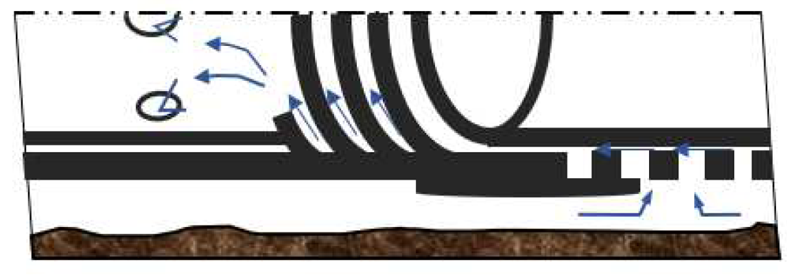
Figure 2.
Schematic diagram of multi-segment method.
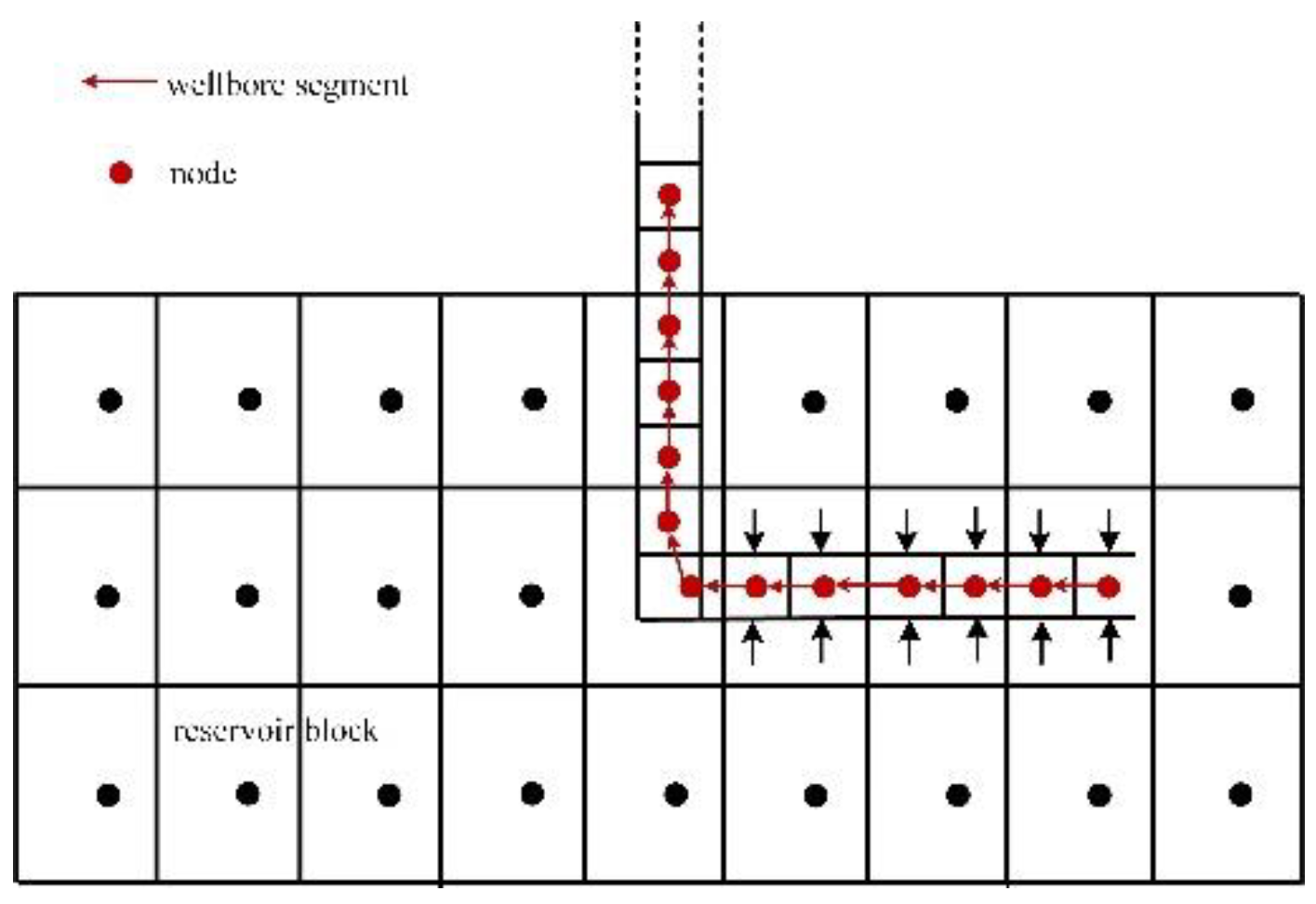
Figure 3.
Schematic diagram of horizontal well with gravel pack combined with ICDs.
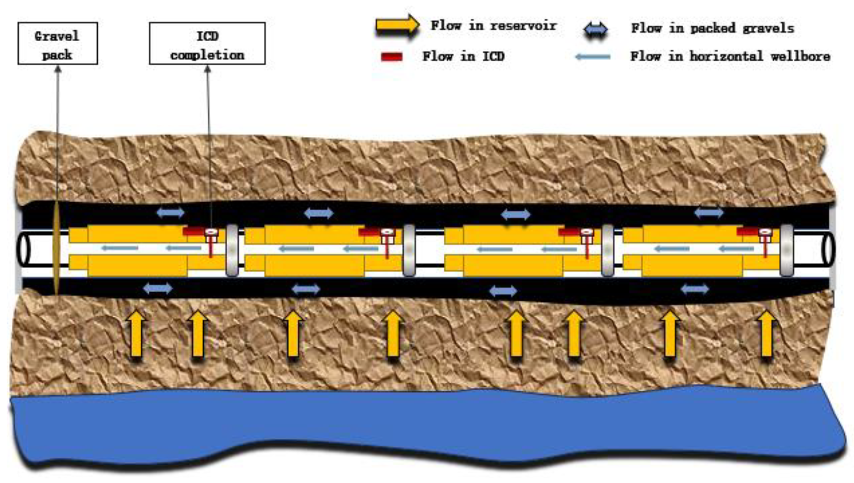
Figure 4.
Flow chart for solving the coupled model.
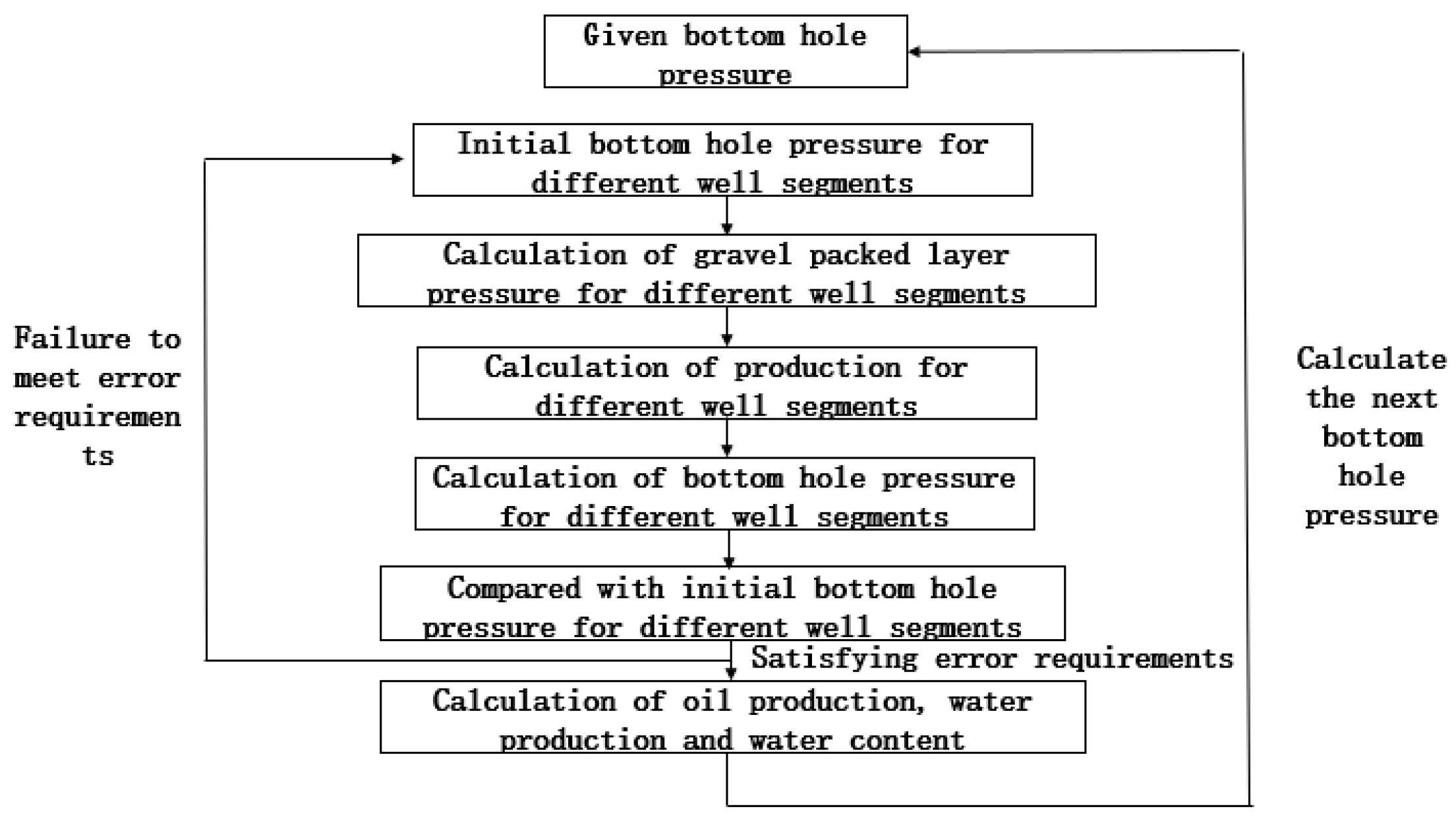
Figure 5.
Flow chart for solving the coupled model.
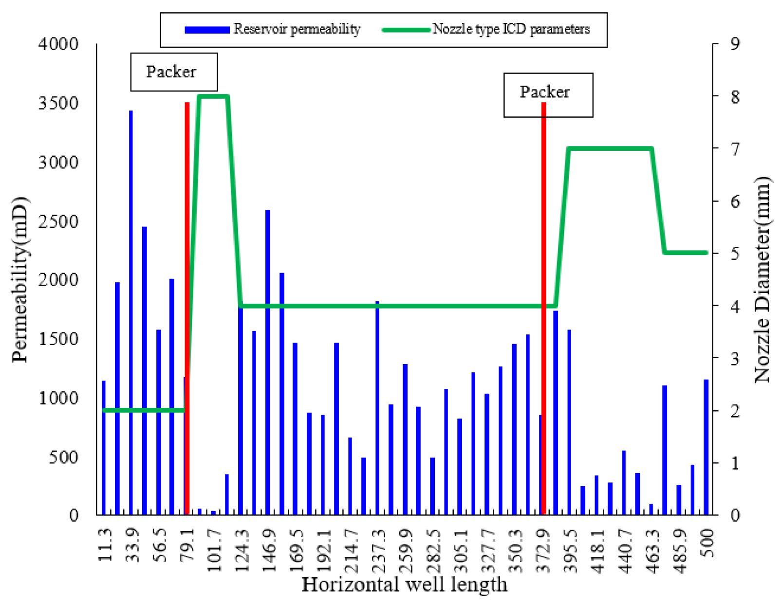
Figure 6.
Comparison of water control effects of different oil viscosities.
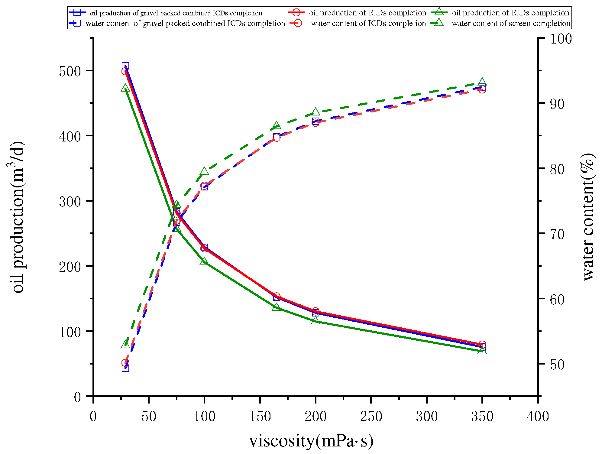
Figure 7.
Comparison of water control effects of different reservoir permeability.
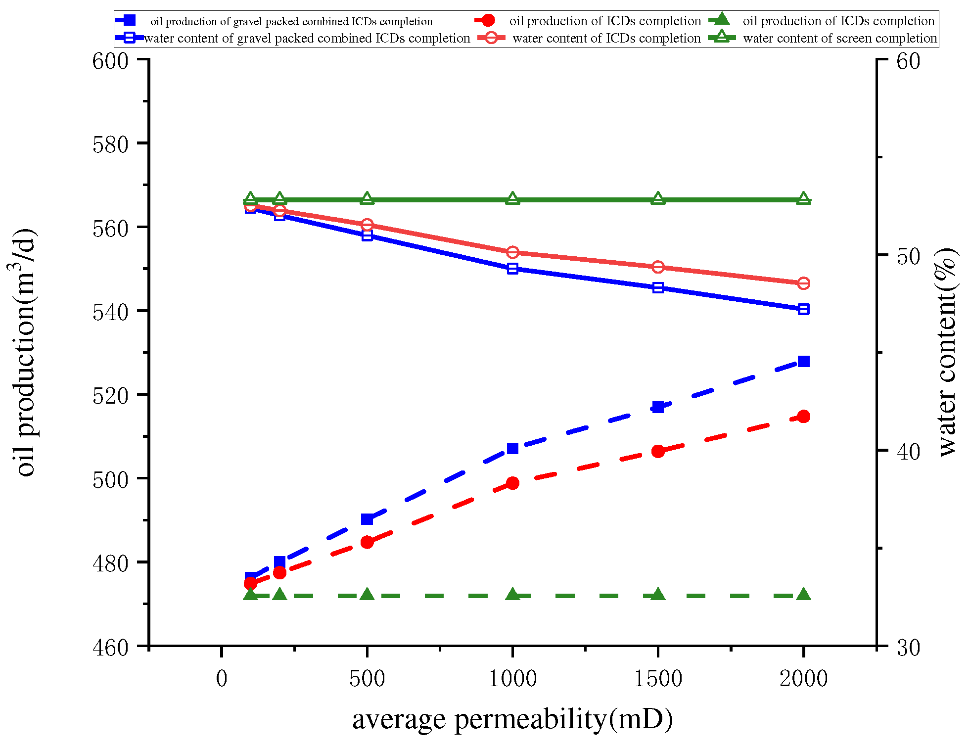
Figure 8.
Comparison of water control effects of different gravel packed layer permeability.
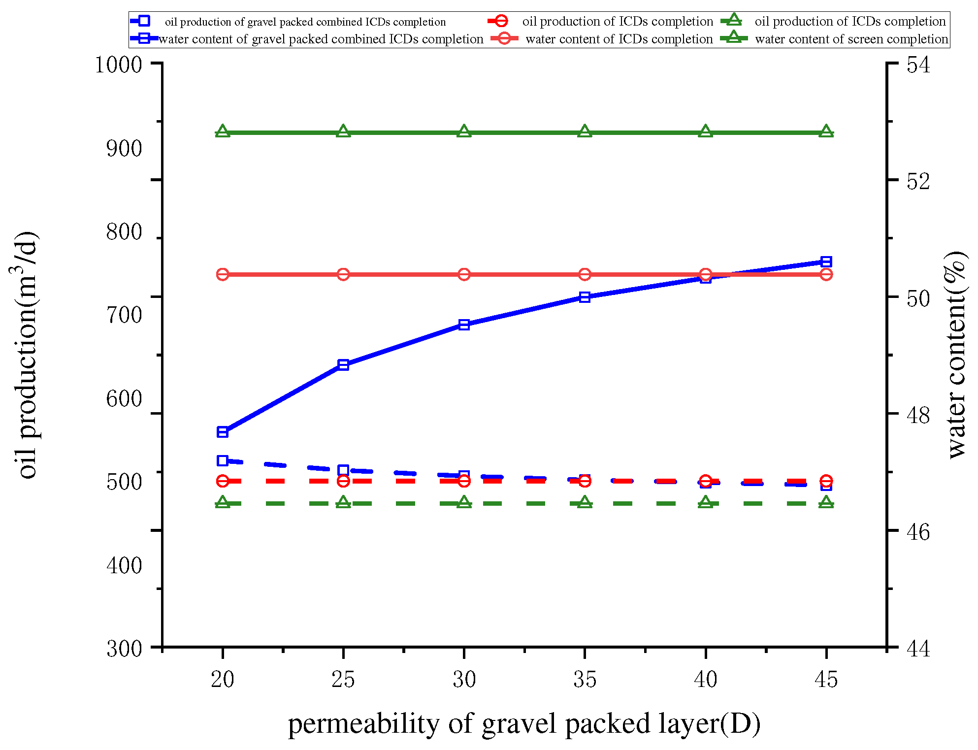
Figure 9.
Distribution of saturation at different production stages.
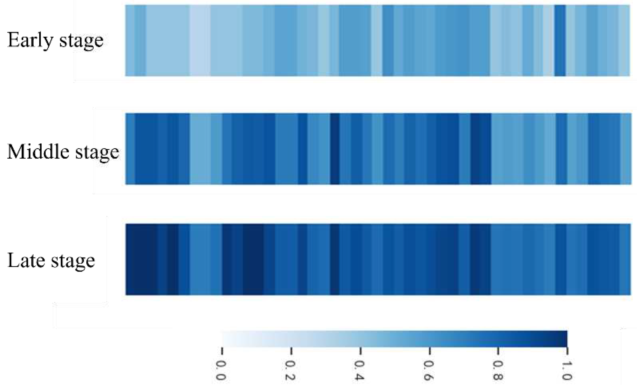
Figure 10.
Comparison of water control effects of different production stage
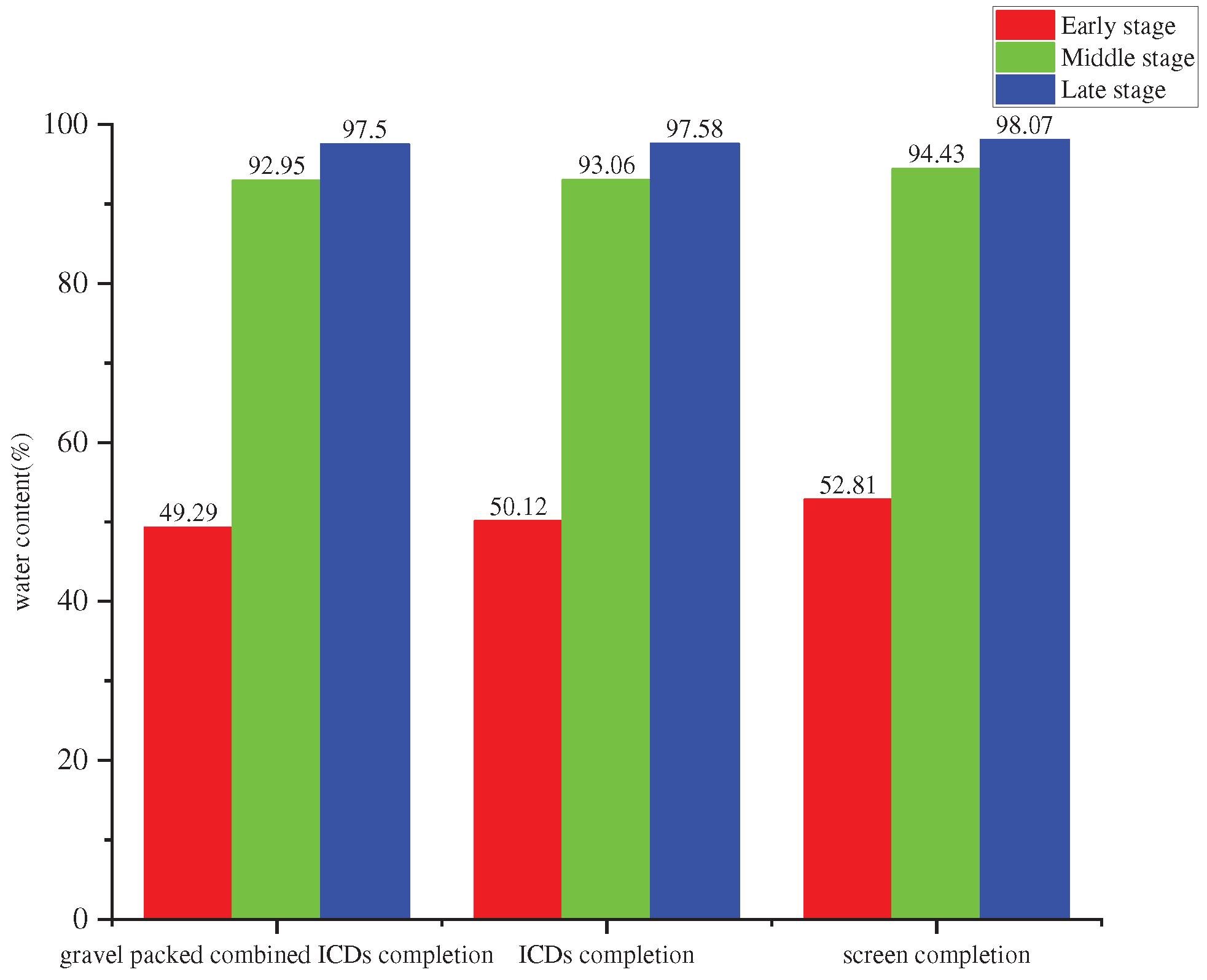

Table 1.
Basic reservoir and fluid parameters.
| Parameters | Values |
|---|---|
| Formation temperature(℃) | 85 |
| The thickness of the reservoir(m) | 11 |
| original formation pressure(MPa) | 18 |
| Porosity(%) | 25 |
| Viscosity of oil (mPa⋅s) | 30 |
| Density of oil (kg/m3) | 800 |
| Viscosity of water (mPa⋅s) | 0.5 |
| Density of water (kg/m3) | 1000 |
| Initial water Saturation | 0.2 |
| Volume factors of oil | 1.05 |
| Gravel packed layer permeability(μm2) | 25 |
Disclaimer/Publisher’s Note: The statements, opinions and data contained in all publications are solely those of the individual author(s) and contributor(s) and not of MDPI and/or the editor(s). MDPI and/or the editor(s) disclaim responsibility for any injury to people or property resulting from any ideas, methods, instructions or products referred to in the content. |
© 2023 by the authors. Licensee MDPI, Basel, Switzerland. This article is an open access article distributed under the terms and conditions of the Creative Commons Attribution (CC BY) license (http://creativecommons.org/licenses/by/4.0/).
Copyright: This open access article is published under a Creative Commons CC BY 4.0 license, which permit the free download, distribution, and reuse, provided that the author and preprint are cited in any reuse.


