1. Introduction
Current trend in noise control engineering is to design compact and lightweight absorbing partitions able to lower the transmission of low frequency noise components, typically lower than 500 Hz, while minimizing their reflection on one side or on both sides of the structure. In the aeronautical industry, this would help to design fuselage panels that could block during cruise conditions the external low-frequency jet noise components (and the turbulent boundary layer noise that peaks at 600 Hz), but also to improve the cabin acoustical comfort by reducing reflections on the panel internal side. This scenario also occurs at low speed flows in the automotive industry in order to reduce the boundary layer noise transmitted from the roof in a car cabin while achieving modal control of the interior noise, which is a challenging task without active systems at low frequencies. This problem obviously appears in building acoustics when designing an insulating wall, that should also be able to provide boundary absorption in the adjacent rooms, and so to lower their reverberation times and improve speech intelligibility. In both cases, a strong constraint is to use compact and lightweight materials to reduce the embarked mass and fuel consumption in the transportation sector or the cost of the infrastructures in the building sector.
Of interest is to design acoustic metamaterials that can be engineered at subwavelength scales to control sound transmission and reflection on selective spectral bands, especially at low frequencies. The current study considers the optimization of multi-layered (micro-)perforated panels in order to achieve these goals. However, we only consider normally incident plane waves unlike in the previously quoted applications where the excitation impinges from various incidences (jet noise), is modal (car cabin) or is spatially random for both the acoustic and turbulent length scales (boundary layer noise). The normal incidence assumption is expected to provide an upper bound on the acoustical performance that can be achieved. Also, we consider partitions of infinite lateral extent that allow analytical tractability, but the structures are in practice of finite extent with effects of the lateral modes, here included through a lumped impedance formulation.
Previous works have focussed on sound transmission blockage by multi-layer perforates under normal or oblique incidence. The study of two thick perforates separated by a thin air gap of the order or smaller than the holes pitch, the so-called double acoustic fishnet, showed a transmission blockage at a frequency scaling on the inverse of the holes pitch, for a wide range of panel thicknesses and air gap widths [
1,
2]. This blockage is due to coupling between the odd-order modes of the open-ended pipes, constituted by two aligned holes, with the resonant side-branch due to the air gap at the pipe mid-point. However, because of millimetric hole spacing, this blockage occurs at high frequencies, typically 17 kHz in [
2]. Moreover, in the blocked zone of low transmission, large reflections occur on the acoustic fishnet incident side, so that the system is insulating, but also highly reflecting.
In order to broaden the frequency bandwidth of transmission blockage, a structure composed of multilayer periodically-spaced perforated panels has been studied [
3] and its transmission properties verified experimentally under normal incidence. Sound transmission stop bands and pass bands were predicted by Bloch-Floquet analysis and observed up to 20 kHz when increasing the number of perforated panels. Parametric studies showed that the broadest stop band occurred for equal panel and gap thicknesses and for panels with a low perforation ratio. However, it is accompanied by a frequency zone of large back-reflection toward the incident side. Also, the sound transmission at low frequencies in the first pass band is still significant. In order to further reduce the low-frequency sound transmitted in the first pass-band, membrane-coated multi-layer perforates have been studied [
4]. It was shown that the ultrathin membranes become very rigid at low frequencies so that they efficiently block the low-frequency sound transmitted on the first pass band, but this is made at the expense of large back reflections.
Recent studies have addressed the challenging problem of designing meta-materials of sub-wavelength thickness able to reduce both sound reflection and transmission, the so-called acoustic leakages. An idea is to design a functionally-graded partition that traps and fully dissipates these leakages by visco-thermal effects. A criterion, the critical coupling condition, has been formulated [
5] that would be useful to analyse this effect. If the visco-thermal losses in the material exactly compensate the amount of leakages out of the system, then the incident power is fully dissipated within the system. In other words, the incident acoustical energy enters and is fully trapped and absorbed within the material, so that no energy comes out of the system, either from reflection or transmission. This has been applied for rigidly-backed systems such as slits loaded by Helmholtz resonators [
6] whose neck dissipative properties balance the amount of energy back-reflected. More recently, the critical coupling condition has been used to limit both reflection and transmission assuming a one-sided excitation of the system, e.g., to achieve a unidirectional perfect absorber. This has been applied to the design of a chirped multi-layer porous material [
7] and of a rainbow trapping absorber made up of a series of Helmholtz resonators whose cavity depth monotonically increases in order to fulfil the critical coupling condition at each resonator position [
8]. Note that these two latter configurations are special cases of axial functionally-graded materials, e.g., materials whose inner geometrical or mechanical properties gradually vary along the main propagation direction in order to achieve a given acoustical performance. Lately, a 3D printed functionally graded material (2.4 cm thick) has been designed constituted of two porous sections of increasing filling fraction backed by a plain panel to ensure near zero transmission. Impedance tube measurements showed that both reflection and transmission were near zero around 3 kHz [
9]. Optimizing parallel arrays of coiled quarter-wavelength resonators from causal-based constraints also enabled to achieve broadband high dissipation, with however ripples that can be smoothed out by adding either porous foam on the resonators apertures [
10] or suitably-tuned micro-perforated panels [
11] as a more robust solution.
The current study builds upon the idea of enhancing over a large bandwidth the absorption and transmission properties of a functionally-graded material made up of alternating layers of thin air and (micro-)perforated plates whose filling fraction, that depends on the perforation ratio, can be optimized along the propagation direction across the material. A key constraint is to achieve a unidirectional perfect absorber at low- to mid- frequencies, below 1 kHz, whilst keeping a subwavelength overall thickness of the system. The novelty is to assess the vibrational effect of limp membranes or resonating thin panels on the optimized acoustical performance of the multi-layered partition. It has essentially been addressed on micro-perforated absorbers when analysing the interaction between the first micro-perforated panel modes and a single Helmholtz resonance [
12,
13], but not a set of Helmholtz-type resonances, as those induced by acoustic fishnet or functionally-graded metamaterials. Dampening of panel vibrations by the micro-perforations themselves has also been studied [
14].
Section 2 presents the cost-efficient impedance translation method used to predict the dissipative and reactive properties of multi-layered (micro-)perforated partitions and to account for elastic or resonating panels. It is shown how unit dissipation peaks can be analysed by a scattering matrix approach.
Section 3 shows through parametric studies the performance of acoustic fishnets made up of identical (micro-)perforated thin membranes or panels and the influence of their vibrations.
Section 4 extends these parametric studies to the case of functionally-graded elastic (micro-)perforates whose broadband dissipative properties are optimized by simulated annealing method.
Section 5 analyses how the vibrational effects of elastic limp membranes or of thin resonant panels favors or impede the broadband acoustical performance of acoustic fishnets or functionally-graded (micro-) perforated partitions.
2. Methods
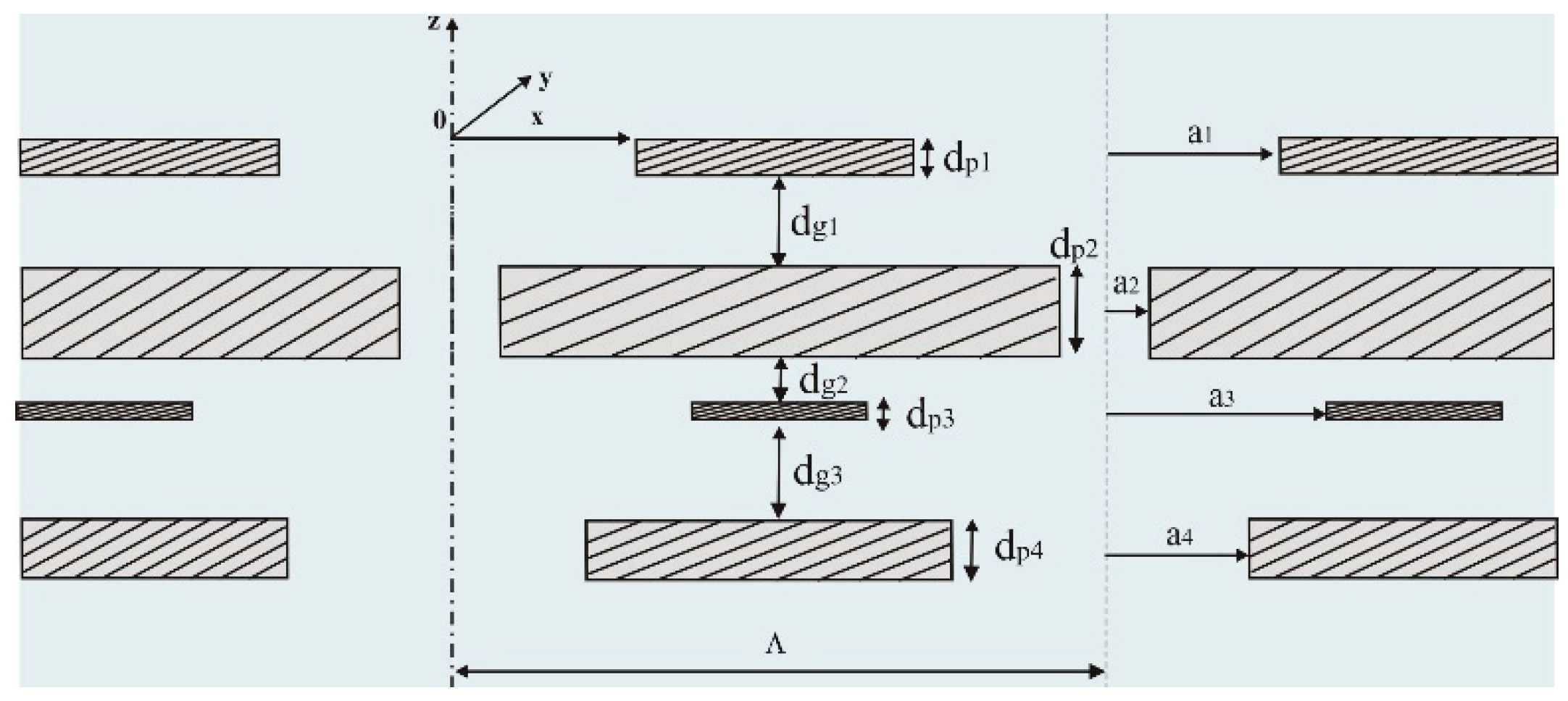
The following methods are described, the impedance translation technique and the scattering matrix formulation, that will be respectively used to simulate, optimize and analyse the acoustical performance of unbacked multi-layer (micro-) perforated partitions. The studied partitions consists of an arbitrary sequence of
thin rigid perforated panels of thickness
separated by
air gaps of depth
, as depicted in
Figure 1 for an unbacked double-layer partition.
The panels are coined micro-perforated when the radius of the circular perforations is lower than 0.5 mm. The holes pitch of the nth panel is denoted , with , and the corresponding perforation ratio reads , assuming aligned holes over each panel. The N-layered partition is assumed to be laterally of infinite extent and undergoes normal plane wave incidence.
2.1. Impedance Translation Method
The impedance translation method (ITM) considers each (micro-)perforated panel, termed (M)PP, as an element characterized by its effective transfer impedance
, assuming a sufficient number of holes per acoustic wavelength
, typically
. The
nth (M)PP has circular holes that can be assimilated to short narrow tubes whose inner acoustic axial velocity
, averaged over the hole surface, is driven by the pressure difference
on either side of the holes, so that
. Assuming viscous losses within the holes and an omitted time-dependence
, with
the angular frequency, Maa’s formulation [
15] for the effective transfer impedance of the
nth (M)PP takes the form
as a function of
the Shear number, ratio of the holes radius to the in-hole viscous boundary layer thickness
with
the air dynamic viscosity and
the air density. Equation (1) can be rewritten as
where the inner term,
with
, accounts for viscous dissipation and inertial effects inside the holes, whereas the outer terms,
and
, gathered in
, respectively account for outer frictional losses and air motion inertial effects at the inlet/outlet of the holes, with
the added-length correction factor neglecting holes interaction. If
, e.g., when
, acoustic flow interaction between the holes lowers the external added-length induced by the outer inertial effects. This correction is accounted for through Fok’s function
[
16], a monotonically decreasing function of
, in the added-length correction factor such that
in the general case.
In the ITM, incident and reflected travelling wave solutions are written separately within each of the air layers in terms of the acoustic pressure and particle velocity. Boundary conditions such as jump of pressure,
, and continuity of the surface-averaged axial velocity
are applied across each (M)PP, leading to recursive expressions for the input impedance of the first panel in terms of the transfer impedance of the first panel, plus the input impedance of the first air gap, itself a function of the second panel input impedance, and so on, until the last panel backed by the air characteristic impedance
with
the sound speed. The input impedances,
, at the surfaces of each panel-cavity section (
) are thus related by
with
the acoustic wavenumber and
. The transfer impedance,
, across the multilayered partition is obtained as
The absorption coefficient of the partition in the impedance translation method is defined as , with , the normal incidence reflection coefficient and obtained from Equation (2). The transmission loss (TL) is defined by , with and , the normal incidence transmission coefficient. Part of the incident power not reflected, nor transmitted, is dissipated through the partition and is calculated as .
2.2. Scattering Matrix Formulation
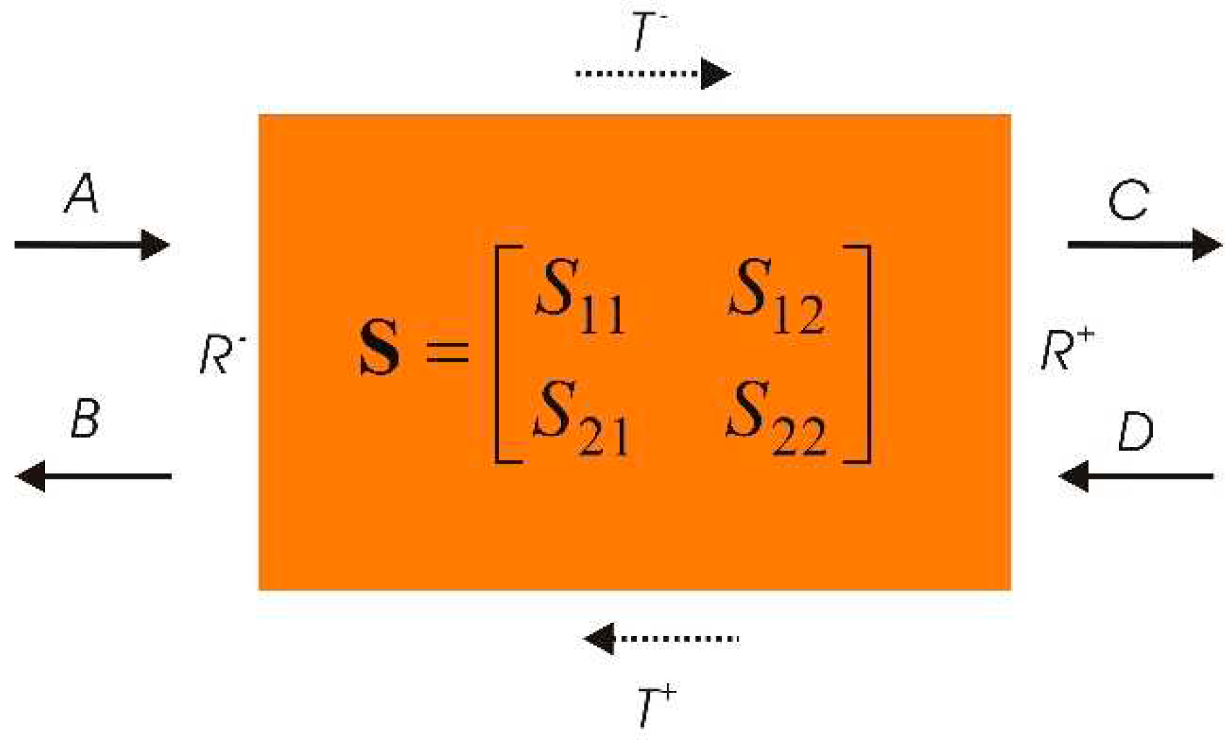
The acoustic performance of the multi-layered (M)PP partition can be analysed from the algebraic properties of its scattering matrix, sketched in
Figure 2. Given a dissipative system such as the (M)PP partition, when critical coupling is achieved at a specific frequency, then the dissipation is equal to one. All the incident energy entering the system is dissipated by visco-thermal effects and there are no waves going out of the system. Following the notations of
Figure 2, A and D denote the incident waves entering the system from either side and B, C the waves, respectively reflected and transmitted, going out of the system. It is then necessary that B=0 and C=0 to achieve the critical coupling condition (CCC).
More precisely, the outgoing wave amplitudes [C B] are related to the ingoing waves amplitudes [A D] by the scattering matrix
S as follows:
where
depends on the left (
), right (
) reflection coefficients and of the transmission coefficient
. This last property is true, even if the system is not symmetric whereas
is only valid if the system is symmetric.
The CCC requires that
, which can also be formulated as the following eigenvalue problem
, with
, the eigenvalues of
, and
the eigenvectors associated to the null eigenvalues of
. CCC is achieved when
, e.g., when the two eigenvalues are zero-valued at the same frequency. Previous works [
5] have further considered a complex frequency that reads
to account for losses in the system. CCC is then achieved in the complex frequency plane when
while
, e.g., when the losses equate the amount of leakages (reflection, transmission). This approach will be useful to interpret the resonance redistribution of optimized FGPs in subsection 4.3.
3. Acoustic Performance of Multi-Layered Identical (M)PPs
The ITM is used to predict the acoustical performance (dissipation, reflection, transmission under normal incidence) of a partition of overall depth 43 mm, made up of 6 identical rigid (M)PPs of thickness 0.5 mm, holes pitch 8 mm, separated by small air gaps of 8 mm (
). Such holey partition with identical (M)PPs separated by thin air gaps is also coined acoustic fishnet [
1]. Its performance are examined in
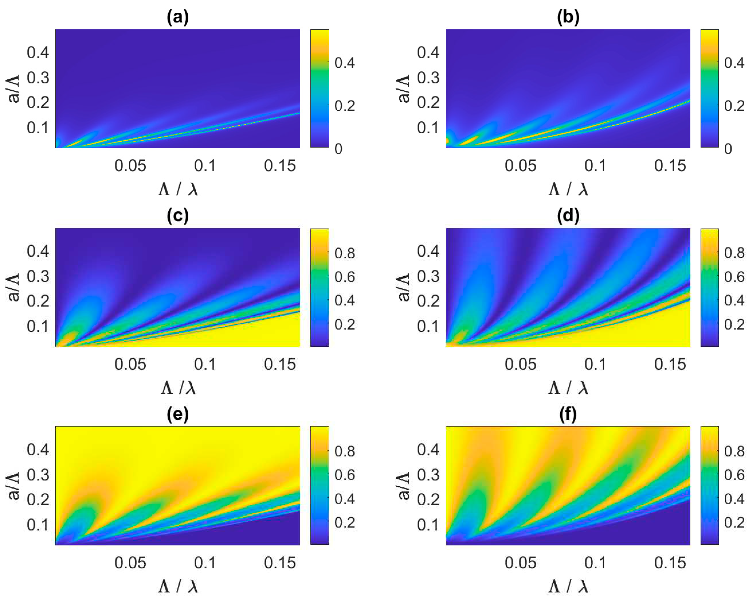
Figure 3,
Figure 4 and
Figure 5 over a broad range of frequencies from 10 Hz to 7 kHz, e.g., from
2.3 10
−4 to 0.1633 with
the acoustic wavelength, when varying the holes radius of each (M)PP from 0.1 mm to 3.9 mm, e.g., from
0.0125 to 0.4875 in units of
. Note that the effective Maa’s model described in
Section 2 fails to be valid if there are less than 4 holes per wavelength, e.g., when
.
3.1. The Acoustic Fishnet Performance
One observes in
Figure 3a band gap structure whose bandwidth broadens when the holes radius increases. For instance, the first pass-band extends up to
(3400 Hz) for
(
) whereas it goes up to
(6375 Hz) when
(
).
Figure 3b,d,f show that, beyond the first pass-band, a first stop-band occurs with total reflection, no transmission and no dissipation. This band gap pattern is typical of periodic multi-layer partitions made up of
panels, leading here to
Hole-Cavity (HC) resonances in each pass band. These HC resonances appear in the first pass-band through peaks of dissipation and transmission whereas they result in dips of reflection. The HC resonances are due to air mass in the panel holes coupled to air stiffness in the gap. They increase when the holes radius increases. Indeed, from Equation (1), the effective mass in the holes,
, decreases (as
) so that the HC resonance frequencies increase.
Comparing
Figure 3a,c,e obtained from the enhanced modal matching (EMM) method [
17], respectively to
Figure 3b,d,f obtained from the ITM, shows a very good correlation as long as
(
), e.g., for a partition made up of MPPs. For perforated partitions (
), the trends are still captured by the ITM, although with a power law dependence of the HC resonance frequency with respect to
, all the more than the panels porosity is high. Indeed, the EMM, validated against Finite Element visco-thermal modelling of multi-layered (M)PP partitions [
17], fully accounts for non-planar in-hole modes and evanescent waves in the air gaps whereas only normal plane waves are assumed in the ITM. The latter method is computationally much less expensive than the former, thus more conducive to optimization studies.
3.2. Influence of the (M)PP Vibrations on the Acoustic Fishnet Performance
In order to describe the effect of the (M)PP vibrations on the acoustical performance of the multi-layered partition, the ITM has been extended to account for thin elastic limp sheets (panels or membranes) and for the first volumetric mode of the panels.
Under normal incidence, the transfer impedance of the
nth elastic panel of density
reduces to
. As the lightweight panel vibrates due to the pressure difference
, the acoustic particle velocity at the holes wall is not anymore zero (as is the case for rigid panels), but equates the panel normal velocity. It results in the following modified expression of Equation (1) for the overall transfer impedance a thin elastic panel or membrane [
18]
A second modified version of Equation (1) is proposed accounting for the effect of the first volumetric resonance of the vibrating panels when it falls within the efficiency bandwidth of the multi-layered partition. It results in the modified overall transfer impedance in which is the transfer impedance of the rigid (micro-)perforated panel given by Equation (1) and in which is the nth panel first mode impedance with the corresponding squared norm of the mode, the damping ratio of the first panel mode and the first mode angular resonance frequency of the nth panel.
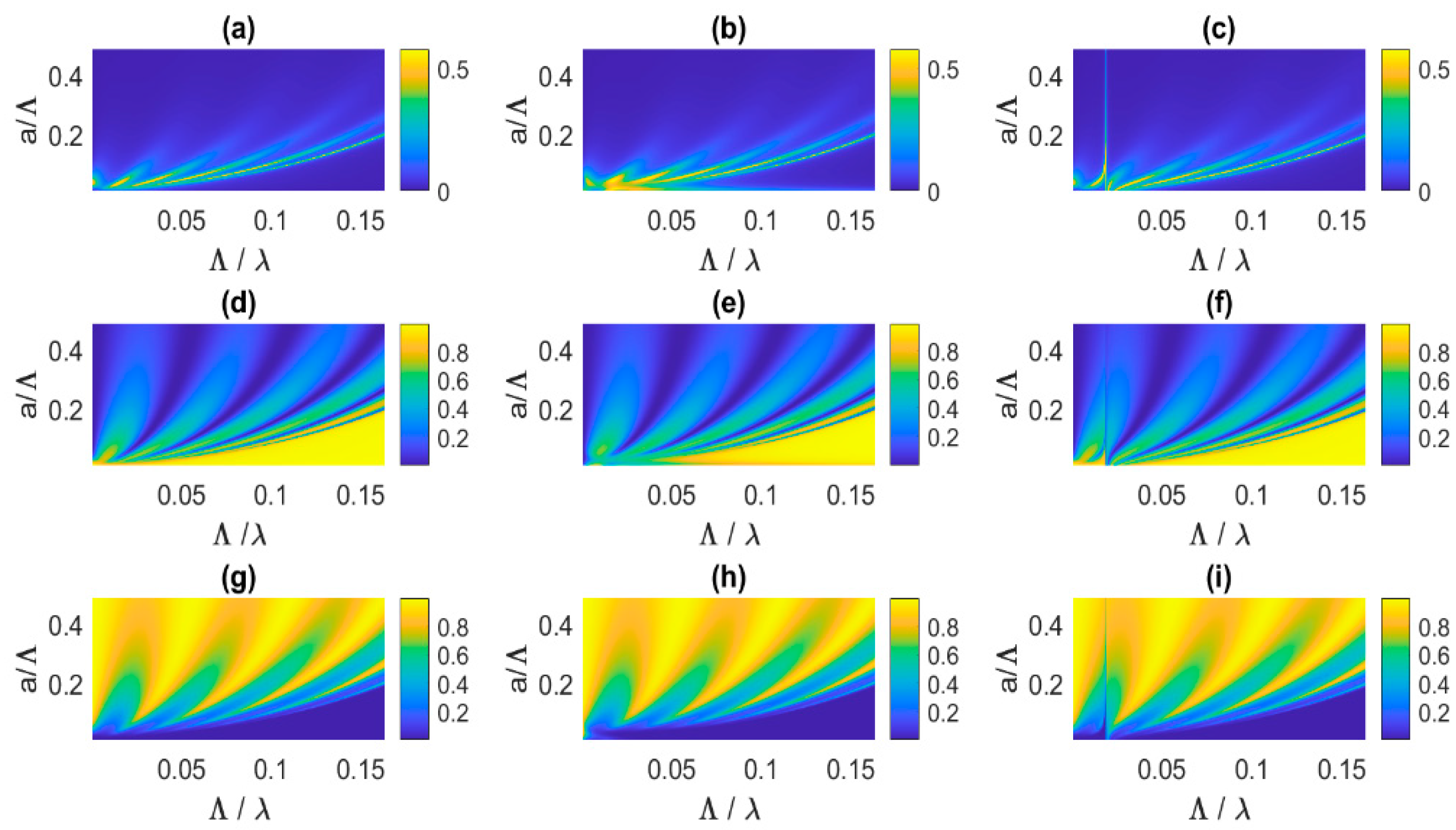
Figure 4 shows the effect of elasticity and modal vibrations on the acoustic performance (dissipation, reflection, transmission) of the 5-layer acoustic fishnet for a broad range of variations in
in units of
.
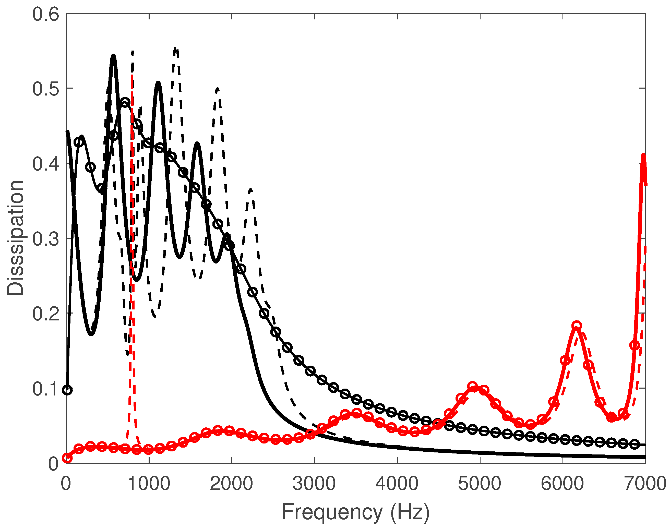
Figure 5 shows these effects on the dissipation spectra assuming micro-perforated panels with
and perforated panels with
. The elastic limp membranes have a surface density of 0.08 kg/m
2, typical of low density polyethylene films, whereas the resonant vibrating panels in aluminum have a surface density of 1.25 kg/m
2 and a resonance frequency of the first volumetric mode set to
. A damping ratio of
1% has been chosen and
calculated [
19] assuming a circular panel clamped along its edges.
It can be seen from
Figure 4b,b,h and
Figure 5 that the limp membranes dampen the dissipation peaks that contribute to the first pass-band of the micro-perforated acoustic fishnet as long as
(
) and
. It can be shown from Equations (1) and (5) that the inertial membrane impedance
contributes to increase the overall specific resistance of
, thereby broadening and merging the first pass-band resonances, as seen in the black curves with circles of
Figure 5. Meanwhile, the transmission peaks and the reflection dips are also dampened. However, for perforated acoustic fishnets (
), the limp membranes have minute effects whatever
due to the already low resistances of the rigid perforates with large perforation ratio, as seen in the red curves with circles of
Figure 5.
Figure 4c,f,i and
Figure 5 show that the panels first mode produces a narrowband dissipation peak around 800 Hz whatever
, associated to a sharp reflection and transmission dip. However, this volumetric mode has different effects over the pass-band whether the fishnet is made up of microperforates or perforates. As for microperforates (
,
), its resonance frequency at 800 Hz falls within the half-bandwidths of the HC acoustical resonances gathered in the first pass-band. It results in a strong coupling with these resonances, upshifting (resp. downshifting) the HC resonances above (resp. below) 800 Hz, as it decreases (resp. increases) their acoustic reactance. As a result, accounting for the panels first volumetric mode enlarges the first pass-band. It also tends to lower (resp. increase) the acoustic resistance of the HC resonances located above (resp. below)
. This is accompanied by a decrease (resp. increase) of the associated reflection dips and an increase (resp. decrease) of the transmission peaks of the HC resonances above (resp. below)
. As for perforates (
,
), the panels volumetric mode weakly cross-couples with the neighboring HC resonances, much widely spaced in frequency. It still contributes as a sharp dissipation peak at
but with a dampening and downshifting effect on the HC resonances all the more low that
increases. It can be seen from
Figure 5 (red dashed curve) that the latter effect is negligible for
.
4. Acoustic Performance of Multi-Layered Functionally-Graded (M)PPs
Imposing constant holes radius and perforation ratio for all the panels of the partition ensures the occurrence of pass-bands and stop-bands. However, the stop-band occurs at quite high frequencies (above 3 kHz as seen in
Section 3 for
) and the pass-band is made up of narrow peak distribution induced by the HC resonances, that may merge due to vibration effects. As such, the acoustical performance of acoustic fishnets thus appear to be moderate at low-mid frequencies below 1 kHz. Better performance could be obtained over this frequency range with a proper selection of the holes radii for each panel constituting the partition. A key idea would be to achieve both impedance matching and high visco-thermal dissipation as the incident wave enters the partition through the holes. This could be obtained by letting the holes radii decreasing across the fishnet following a chirp distribution that has to be optimised for any of the (micro-) perforated plates constituting the complete partition. A constraint would be to keep the partition overall length subwavelength, thus leading to a compact multi-layered functionally-graded partition, coined FGP. This objective will be carried out through an optimization study that takes into consideration both the transmitted and reflected powers to ensure maximum dissipation of the incident power inside the partition.
4.1. Broadband Optimization of FGPs
A proper selection of the optimal holes radii distribution across the FGP is a combinatorial optimization problem where all the physical parameters are cross-related in the sense that variation of any of the parameters may significantly affect the others. The selected cost function, the frequency-averaged dissipation in the low frequency range, can also present many sub-optimal maxima and classical gradient-based optimization algorithms take the risk of being trapped in these non-optimal solutions. It is then necessary to use other optimization techniques, such as natural algorithms, a special class of global metaheuristic optimization processes, that reproduce physical selection mechanisms present in real life. In this work, we have used the simulating annealing (SA) optimization method [
20] to find the optimal holes radii distribution that globally maximise the total sound power dissipated by the FGP between 10 Hz and 1 kHz.
The fixed parameters for the FGP are the panels thickness, set to 0.5 mm, the holes pitch set to 20 mm and the overall thickness of the system, 300 mm, that stays subwavelength up to 1150 Hz. This leads to an air gap thickness 15.3 mm. Twenty perforated panels were used, assuming a monotonically decreasing chirped distribution of the holes radii along the direction of wave propagation such as with and the chirp parameter being optimised.
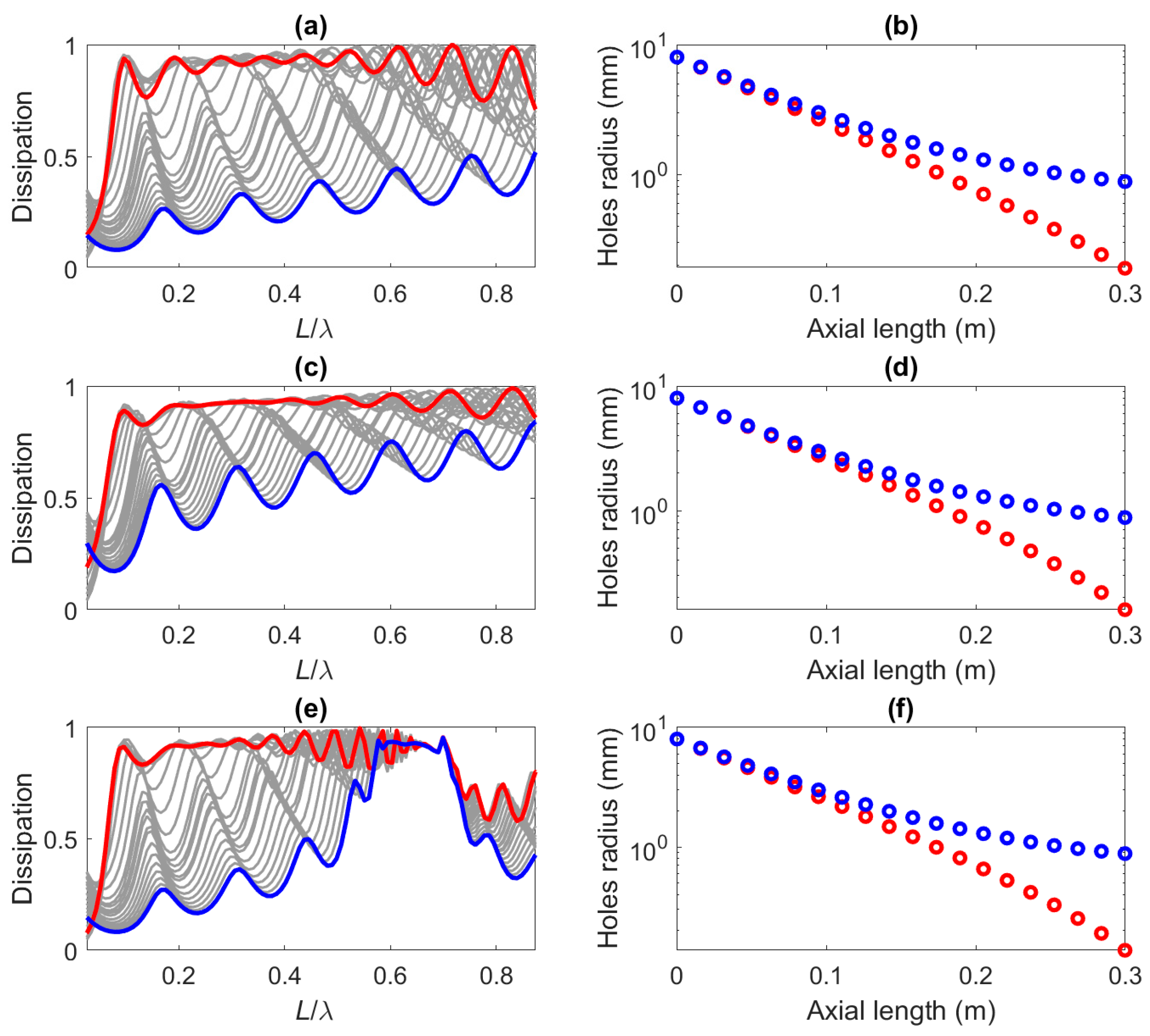
Figures 6a presents the dissipation of the rigid partition over the optimization bandwidth for a number of holes radii distributions selected while the SA algorithm was running (shown as grey curves). It can be seen that wide differences can be found in the performance results depending on a proper selection of the holes radii. The red curve corresponds to the optimal dissipation results, that maximise the average dissipation of the system in the targeted frequency range, leading to a broadband dissipation coefficient that stays above 0.7 between 88 Hz and 990 Hz, with perfect dissipation at 820 Hz (
). On the other hand, the blue curve corresponds to the holes radii distribution that provides the worst results. The holes radii distributions of both extreme physical configurations are presented in
Figure 6b along the axial length of the partition. It should be pointed out that the best and worst solutions start with identical holes radii on the front perforated panel (
8 mm), but the differences between both solutions become more important as one progresses towards the partition transmitting side. The worst solution is conducive to a fully-perforated FGP (
0.9 mm), whereas the best solution exhibits an almost linear decay of the holes radii across the partition with only the four last panels micro-perforated (down to
0.2 mm). Thus, a proper selection of the FGP holes radii distribution plays a crucial role that makes the optimization procedure unavoidable when tailoring the FGP noise control performance towards specific frequency bands.
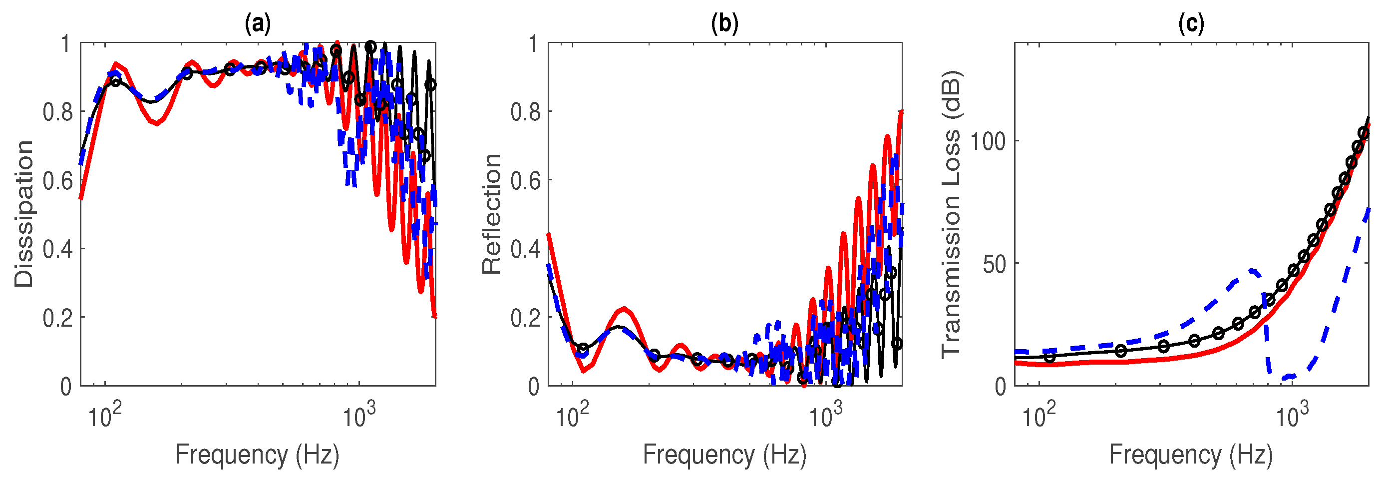
Figure 6a and
Figure 7 show that the worst solution leads to low dissipation performance induced by very few isolated HC resonances activated up to 1 kHz whereas the best solution enables grouping and merging of these resonances over the targeted frequency range (except the first HC resonance at 110 Hz), thereby broadening the acoustical performance of the FGP in the low-mid frequency range.
Figure 7b,c show that the reflection coefficient does not exceed 0.2 over this bandwidth while the TL stays between 8dB and 35dB. (resp. TL). This is reminiscent of the performance of Acoustic Black Holes [
21] that trap and dissipate incident waves over a large bandwidth. As expected, the dissipation shown in
Figure 7 decays above 1 kHz. This is accompanied by an increase in the reflected power, but the TL still increases with frequency above 1 kHz.
4.2. Vibrational Effects on the Broadband Optimization of FGPs
SA optimization has also been performed cost-efficiently by accounting for limp (micro-)perforated membranes and resonant vibrating panels in the ITM. As already observed in
Section 3, the membranes inertial impedance
contribute to increase the overall specific resistance
of the (micro-)perforated membranes, thereby broadening the individual half-bandwidth resonances and favoring the merging of the first 8 HC resonances up to 1 kHz (
). As shown in
Figure 6c, it provides less dissipation ripples over the efficiency bandwidth and at least equal or better performance in both dissipation, reflection and transmission with respect to the rigid optimal FGP, as seen in
Figure 7.
The optimization of FGPs with all panels vibrating on their first volumetric mode resonant at 800 Hz shows in
Figure 6e and
Figure 7a high plateau of dissipation (greater than 0.9) with ripples occurring towards 800 Hz followed by a peak of dissipation at the structural resonance and then a drop of dissipation above 800 Hz. It is accompanied by a drop of TL (or a large transmission) that can be seen in
Figure 7c between 800 Hz and 1200 Hz. Therefore, the effect of the vibrating panels is to reduce the efficiency range of the resonant FGP up to
, the panels first resonance frequency induced by its volumetric mode. Assuming lower values of
further reduces the FGP efficiency range and leads to a similar scenario: a high-valued dissipation plateau as well as a high TL with an accumulation of merged resonances up to
, followed by a drop in dissipation above
. Therefore, the upper bound for optimization of FGPs with vibrating (micro-)perforated panels with identical first volumetric resonance
should be chosen as
. Alternatively,
could be considered as a design variable up to which optimization of FGPs provides high performance.
It is of interest to note that the optimal FGP performance are achieved for very similar holes radii distributions, as observed when comparing the red circle curves in
Figure 6b,d,f, with differences lower than 0.1 mm (resp. 0.05 mm), between the optimal holes distributions of elastic (resp. resonant) FGPs with respect to the rigid FGP. It shows how the optimal decay of the holes radius is robust to vibrational effects incorporated into the models.
4.3. Critical Coupling Analysis
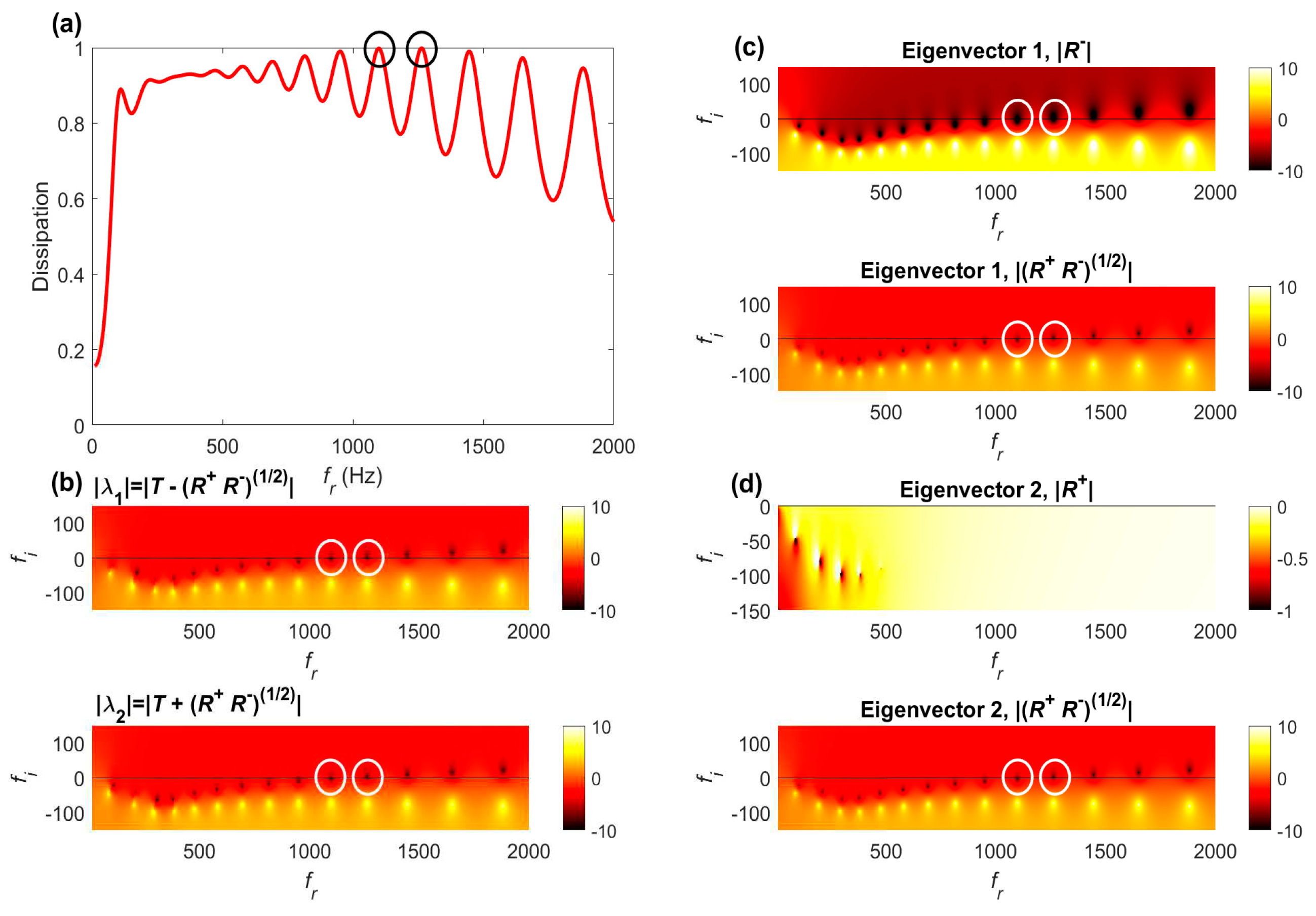
One approach to analyse the acoustic performance of optimized FGPs is to examine the zero-poles placement of the scattering matrix eigenvalues/eigenvectors in the complex frequency plane. In the lossless case (if
and
), they are located symmetrical with respect to the real frequency axes, as discussed in [
5]. When losses are introduced, they are essentially downshifted along the imaginary axis. It occurs that the amount of losses may be balanced by the leakages (reflection, transmission) at specific (positive) frequencies circled in white in
Figure 8,
Figure 9 and
Figure 10. It is associated to unit dissipation peaks at which CCC is achieved, e.g., for frequencies on the real axis at which
. They appear as black dots in these figures. Each zero is associated to a pole, represented as yellow dots, at which
, and so
, is maximum.
4.3.1. Optimization of Rigid FGPs
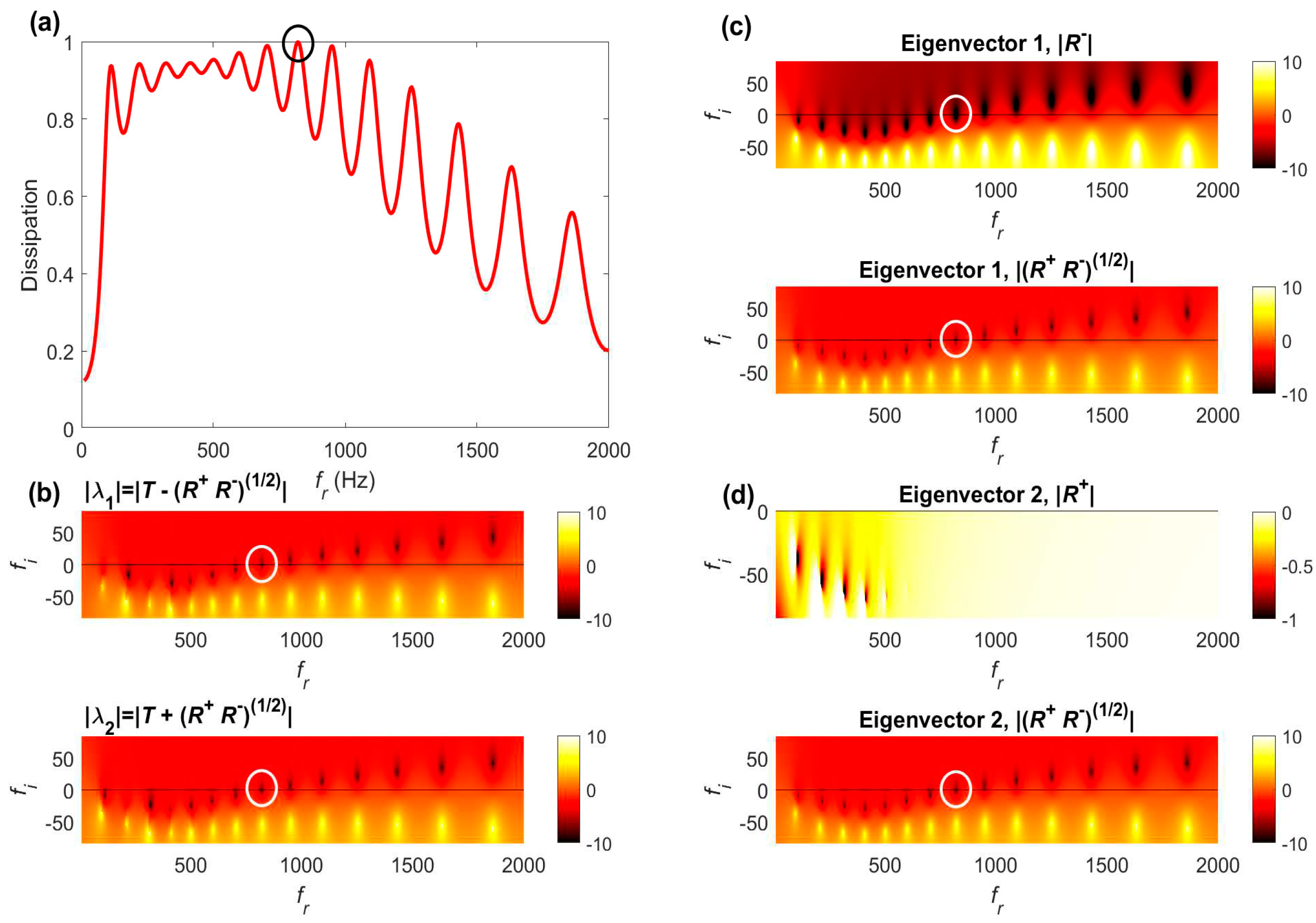
In the case of FGPs with rigid panels, the optimization process led to broadening and merging (to a certain extent) of the first eight HC resonances. The eighth HC resonance [shown as circles in
Figure 8] reaches CCC with unit dissipation peak and
at 823 Hz. Moreover,
Figure 8c shows that both components,
and
, of the first eigenvector associated to
become zero-valued at the same frequency, as they involve
at this frequency, indicating that all the incident waves
coming from the left enters the optimized FGP without reflection nor
transmission at this frequency. Moreover,
Figure 8d shows that only the second component,
of the second eigenvector
associated to
becomes zero-valued at the same frequency (because
R− = 0),
while the other component
is not zero. This means that the CCC is not satisfied for an incident wave entering the optimized FGP from the right, as it should be expected since the system has only been optimized for an incident wave impinging from the left side.
It can be seen from
Figure 8b that optimization of the rigid FGPs led to a redistribution of the HC resonances in two classes: those in over-resistive regime (the first 7 HC resonances) located in the optimization bandwidth below 823 Hz such that
when
, and those in under-resistive regime such that
when
.
4.3.2. Optimization of FGPs with Elastic Limp Membranes
Figure 9 shows that optimization of the FGP with elastic limp membranes, bringing added resistances to the (M)PPs, led to further broadening and merging of the first 11 HC resonances over a larger bandwidth up to 1250 Hz. It extends beyond 1 kHz, the upper frequency bound of optimization range, with the tenth and eleventh HC resonances satisfying CCC, those above 1250 Hz being in under-resistive regime. Note that the y-scales are different between
Figure 8b and
Figure 9b so that the zero-poles locations are further downshifted in
Figure 9b with respect to
Figure 8b, due to added resistance effect by the limp (micro-) perforated membranes. As in the rigid case, only the first eigenvector components vanish when CCC is satisfied, as observed in
Figure 9c,d).
4.3.3. Optimization of FGPs with thin Resonant Vibrating Panels
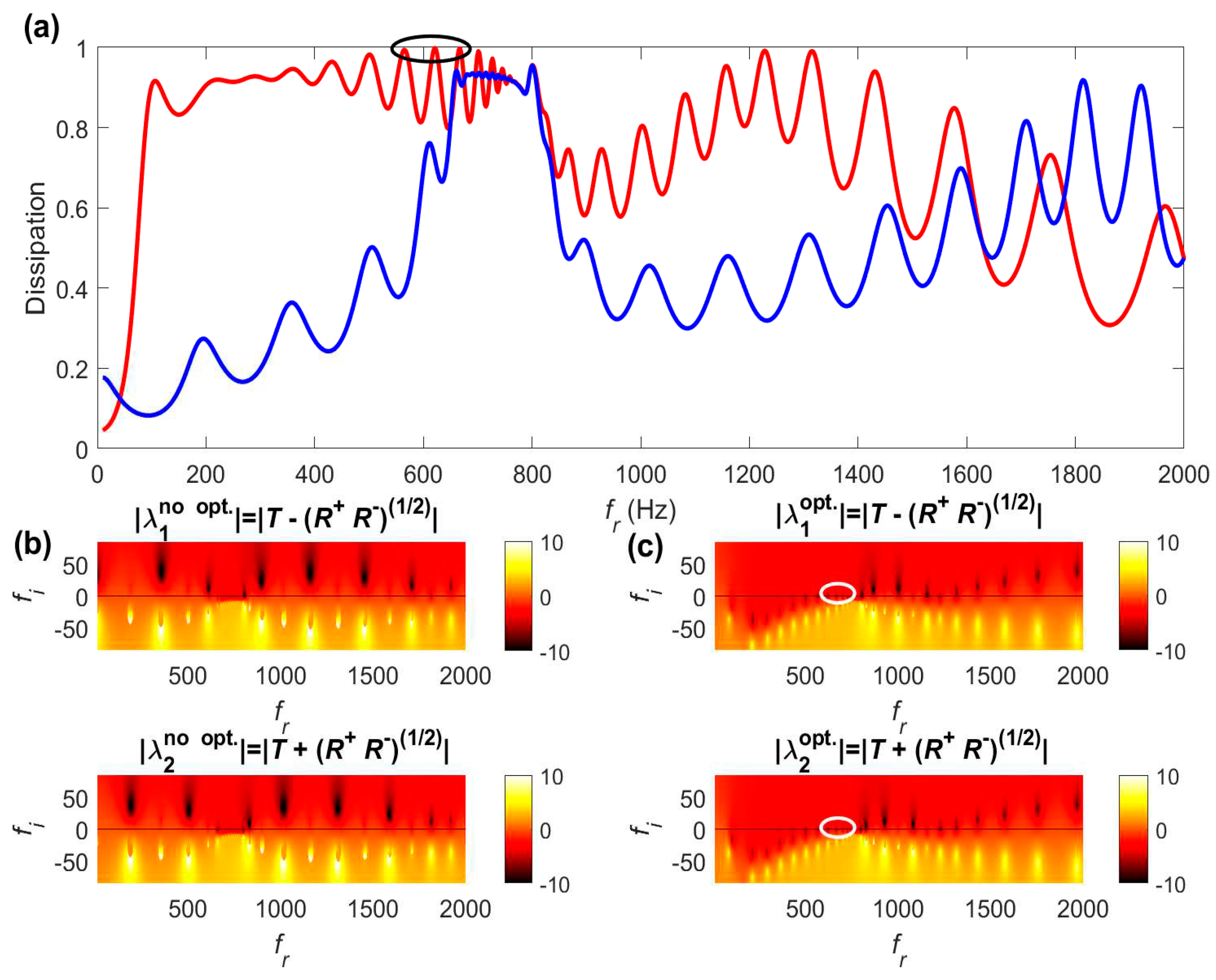
Accounting for the panels volumetric resonant mode results in a significant redistribution of the FGP resonances in the complex frequency plane both before and after optimization. Before optimization, one observes from
Figure 10 a regular set of under-resistive HC resonances associated to moderate dissipation peak values below 0.5, except between 660 Hz and 800 Hz where a plateau of high dissipation values (0.93) occurs. Note that, unlike in the previous cases, one does not spot a one-to-one relation between zeros and poles, since extra-poles are interlaced between consecutive zero-pole pairs. In the high dissipation zone, strong coupling between the panels volumetric mode and the nearby HC resonances led to multi-resonance splitting. One observes in
Figure 10b an accumulation of over-resistive elasto-acoustic panel-HC (P-HC) resonances from 660 Hz up to the panels resonance frequency,
, with pairs of zero-poles getting closer to the real axis as frequency increases towards
. Out of this frequency zone, since all the holes panels are super-millimetric, weak cross-coupling occurs between the panels (P) structural mode and the HC resonances, as seen in subsection 3.2. After optimization,
Figure 10c shows that this narrowband accumulation of P-HC resonances spreads out towards the low-frequencies, due to enhanced cross-coupling over a larger frequency band between P and HC resonances enabled by the micro-perforates (see sub-section 3.2). Moreover, the obtained high dissipation values are favored by the stiffness-like behavior of the vibrating panels impedance when
. The optimization process thus redistributes the P-HC resonances below
and modifies the holes radii distribution to induce CCC at these resonances as if the FGP was made of rigid panels. Above 800 Hz, regular distribution of zero-poles pairs associated to under-resistive HC resonances re-appear in
Figure 10c with a couple of peaks near 1250 Hz close to near-unit dissipation. Although not shown, once again, only the first eigenvector components reflect the CCC that only occurs under left-side excitation before and after optimization.
5. Discussion
In this work, the vibrational effects of two strategies have been assessed on the acoustical performance of either periodic (acoustic fishnet) or functionally-graded (micro-) perforated partitions whether the (micro-) perforated solid parts are made of elastic limp membranes or of thin panels resonant within the partition efficiency range.
The use of (micro-) perforated limb membranes adds a sufficient amount of resistance that broadens and merges the dissipation, reflection and transmission peaks belonging to the first pass-band of micro-perforated acoustic fishnets. It also smoothes out the ripples due to HC resonances over the optimization bandwidth of FGPs with linearly decaying holes radii, thereby achieving almost constant high dissipation values as well as low transmission and reflection over a broad bandwidth from up to . Compared to the optimized rigid FGP that led to a total frequency-averaged dissipation of 0.9 over the optimization bandwidth (10 Hz – 1 kHz), a similar total dissipation of 0.92 is achieved when using limp membranes while avoiding the dissipation dips. They can be made of ultrathin polymer (micro-)perforated membranes. They comply very well with lightweight and cost-effective production of acoustic metamaterials efficient over a broad low-mid frequency range. However, their robustness towards severe environments (high temperatures, high speed flow, oxidant gases…) still requires further research on the material resilience properties.
Conversely, using thin (micro-perforated) panels is a more robust option that can withstand harsh conditions, albeit less lightweight than limp membranes. Because of their sub-millimetric thickness, it is likely that their first resonant volumetric mode falls within the acoustic fishnet or FGP efficiency ranges. On top of generating a narrowband dissipation peak, the first volumetric mode of the micro-perforated panels strongly couples with the neighboring HC resonances, leading to a new set of elasto-acoustic (P-HC) resonances. Such vibrational effect extends the efficiency bandwidth of micro-perforated acoustic fishnets as long as . The resonance frequency of the first mode, , also sets an upper limit to the broadband optimization of FGPs, up to which high dissipation, low reflection and low transmission can be achieved, but beyond which these acoustic indicators exhibit moderate performance. A total frequency-averaged dissipation of 0.86 was achieved up to 1 kHz from an optimized FGP with thin panels mode resonant at 800 Hz, thereby providing a robust sub-wavelength dissipative solution whose bandwidth can be tuned by a proper choice of .
The thin micro-perforated panels constituting the partitions can be produced from additive manufacturing such as stereolithography or laser sintering processes, suitable to produce the smallest holes diameter required for optimized FGPs, e.g., down to 0.26 mm. Note that the optimized FGP partitions are robust to small uncertainties induced by the manufacturing process (typically 0.05 mm for stereolithography) onto the required values of the holes diameter across the partition.
Further works should focus on experimentally testing the vibrational effects of limp membranes or thin resonating panels on optimized acoustic fishnets or FGPs under normal, but also under grazing sound incidences, in order to show the practical efficiency of these sub-wavelength absorbers, not only in building acoustics, but also as lightweight and compact silencing wall-treatments in duct acoustics.
Author Contributions
Conceptualization, T.B. and C.M.; methodology, C.M. and T.B.; software, C.M., validation, T.B.; formal analysis, C.M. and T.B.; investigation, T.B. and C.M.; resources, T.B. and C.M.; data curation, T.B.; writing—original draft preparation, T.B. and C.M.; writing—review and editing, C.M.; visualization, C.M..; supervision, T.B.; project administration, T.B. and C.M.; funding acquisition, T.B. and C.M. All authors have read and agreed to the published version of the manuscript.
Funding
This work is part of the project TED2021-130103B-I00, funded by MCIN/AEI/10.13039/501100011033 and the European Union “NextGenerationEU”/PRTR. It has also received support from the French government under the France 2030 investment plan, as part of the Initiative d’Excellence d’Aix-Marseille Université - A*MIDEX (AMX-19-IET-010).
Data Availability Statement
Data supporting the reported results are available on request.
Conflicts of Interest
The authors declare no conflict of interest.
References
- Christensen, J.; Martinez-Moreno, L.; Garcia-Vidal, F.J. All-angle blockage of sound by an acoustic double-fishnet metamaterial. Appl. Phys. Lett. 2010, 97, 134106. [Google Scholar] [CrossRef]
- Bell, J.S.; Summers, I.R.; Murray, A.R.J.; Hendry, E.; Sambles, J.R.; Hibbins, A.P. Low acoustic transmittance through a holey structure. Phys. Rev. B 2012, 85, 214305. [Google Scholar] [CrossRef]
- N. Akozbek, N.; Mattiucci, N.; Bloemer, M.J.; Sanghadasa, M.; D’Aguanno, G. Manipulating the extraordinary acoustic transmission through metamaterial-based acoustic band gap structures. Appl. Phys. Lett. 2014, 104, 161906. [Google Scholar] [CrossRef]
- Fan, L.; Chen, Z.; Zhang, S.Y.; Ding, J.; Li, X.J.; Zhang, H. An acoustic metamaterial composed of multi-layer membrane-coated perforated plates for low-frequency sound insulation. Appl. Phys. Lett. 2015, 106, 151908. [Google Scholar] [CrossRef]
- Romero-García, V.; Theocharis, G.; Richoux, O.; Pagneux, V. Use of complex frequency plane to design broadband and sub-wavelength absorbers. J. Acoust. Soc. Am. 2016, 139, 3395–3403. [Google Scholar] [CrossRef] [PubMed]
- Jiménez, N.; Huang, H.; Romero-García, V.; Pagneux, V.; Groby, J.P. Ultra-thin metamaterial for perfect and omnidirectional sound absorption. arXiv:1606 2016, 07776, 1–17. [Google Scholar] [CrossRef]
- Jiménez, N.; Romero-García, V.; Cebrecos, A.; Picó, R.; Sánchez Morcillos, V.J.; García-Raffi, L.M. Broadband quasi perfect absorption using chirped multi-layer porous materials. ArXiv 1610 2016, 08011, 1–15. [Google Scholar] [CrossRef]
- Jiménez, N.; Romero-García, V.; Pagneux, V.; Groby, J.P. Rainbow-trapping absorbers: Broadband, perfect and asymmetric sound absorption by subwavelength panels for transmission problems. Sci. Rep. 2017, 7, 13595. [Google Scholar] [CrossRef] [PubMed]
- Guild, M.; Rohde, C.; Tothko, M.; Sieck, C. 3D printed acoustic metamaterial sound absorbers using functionally-graded sonic crystals. In Proceedings of the Euronoise 2018, Heraklion, Greece, 27-31 May 2018. [Google Scholar]
- Yang, M.; Chen, S.; Fu, C.; Sheng, P. Optimal sound-absorbing structures. Mater. Horiz. 2017, 4, 673–680. [Google Scholar] [CrossRef]
- Bravo, T.; Maury, C. Causally-guided acoustic optimization of rigidly-backed micro-perforated partitions: Case studies and experiments. J. Sound Vib. 2022, 523, 116735. [Google Scholar] [CrossRef]
- Lee, Y.; Lee, E.W.M.; Ng, C.F. Sound absorption of a finite flexible micro-perforated panel backed by an air cavity. J. Sound Vib. 2005, 287, 227–243. [Google Scholar] [CrossRef]
- Bravo, T.; Maury, C.; Pinhede, C. Enhancing sound absorption and transmission through flexible multi-layer micro-perforated structures. J. Acoust. Soc. Am. 2013, 134, 3363–3373. [Google Scholar] [CrossRef] [PubMed]
- Gallerand, L.; Legrand, M.; Dupont, T.; Leclaire, P. Vibration and damping analysis of a thin finite-size microperforated plate. J. Sound Vib. 2022, 541, 117295. [Google Scholar] [CrossRef]
- Maa, D. Y Potential of microperforated panel absorber. J. Acoust. Soc. Am. 1998, 104, 2861–2866. [Google Scholar] [CrossRef]
- Melling, T.H. The acoustic impedance of perforates at medium and high sound pressure levels. J. Sound Vib. 1973, 29, 1–65. [Google Scholar] [CrossRef]
- Maury, C.; Bravo, T. Enhanced modal matching method for macro- and micro-perforated plates. J. Sound Vib. 2021, 500, 116042. [Google Scholar] [CrossRef]
- Li, C.; Cazzolato, B.; Zander, A. Acoustic impedance of micro perforated membranes: Velocity continuity condition at the perforation boundary. J. Acoust. Soc. Am. 2016, 139, 93–103. [Google Scholar] [CrossRef] [PubMed]
- Leissa, A.W. Vibrations of Plates, NASA Technical Report SP-160, Washington D. C., U.S.A., 1969.
- Kirkpatrick, S.; Gelatt, Jr. C.D.; Vecchi, M.P. Optimization by Simulated Annealing. Science 1983, 220, 671–680. [Google Scholar] [CrossRef] [PubMed]
- Mi, Y.; Zhai, W.; Cheng, L.; Xi, C.; Yu, X. Wave trapping by acoustic black hole: Simultaneous reduction of sound reflection and transmission. Appl. Phys. Lett 2021, 118, 114101. [Google Scholar] [CrossRef]
Figure 1.
Multi-layer micro-perforated partition.
Figure 1.
Multi-layer micro-perforated partition.
Figure 2.
Dissipative two-port system with incident, reflected and transmitted wave amplitudes used in the scattering matrix formulation.
Figure 2.
Dissipative two-port system with incident, reflected and transmitted wave amplitudes used in the scattering matrix formulation.
Figure 3.
Dissipation (a,b), reflection (c,d) and transmission (e,f) coefficients of a 5-layer acoustic fishnet as a function of the panels hole radii and acoustic wavelength, non-dimensionalised with respect to the holes pitch, simulated by the enhanced modal matching (left column) and by the impedance translation (right column) methods.
Figure 4.
Dissipation (a,b,c), reflection (d,e,f) and transmission (g,h,i) coefficients of a 5-layer acoustic fishnet as a function of the panels hole radii and acoustic wavelength, non-dimensionalised with respect to the holes pitch, when assuming rigid panels (left column), elastic limp membranes (mid column) and resonant vibrating panels (right column), simulated by the impedance translation method.
Figure 5.
Dissipation coefficient of a 5-layer acoustic fishnet made up of micro-perforates (black, , ) or perforates (red, , ) as a function of frequency when assuming rigid panels (plain), elastic limp membranes (circles) and resonant vibrating panels (dashed) simulated by the impedance translation method.
Figure 6.
Dissipation (left) and holes radius variation (right) associated to maximization (red) and minimization (blue) of the total power dissipated up to 1 kHz by a 19-layer micro-perforated FGP using simulated annealing algorithm and assuming rigid panels (a,b), elastic limp membranes (c,d) and resonant vibrating panels (e,f). Grey curves in (a,c,e) show the intermediate dissipation spectra calculated during the optimization process.
Figure 7.
Dissipation (left), reflection (middle) and transmission loss (right) spectra of an optimized 19-layer micro-perforated FGP assuming rigid panels (plain red), elastic limp membranes (circles black) and resonant vibrating panels (dashed black).
Figure 7.
Dissipation (left), reflection (middle) and transmission loss (right) spectra of an optimized 19-layer micro-perforated FGP assuming rigid panels (plain red), elastic limp membranes (circles black) and resonant vibrating panels (dashed black).
Figure 8.
(a) Dissipation spectrum of an optimized 19-layer micro-perforated FGP assuming rigid panels; (b) modulus (log10 values) of the S-matrix eigenvalues in the complex frequency plane; (c) modulus (log10 values) of the eigenvector components associated to in the complex frequency plane; (d) modulus (log10 values) of the eigenvector components associated to in the complex frequency plane. Circles spot the frequency location at which the critical coupling condition occurs.
Figure 9.
(a) Dissipation spectrum of an optimized 19-layer micro-perforated FGP assuming elastic limp membranes; (b) modulus (log10 values) of the S-matrix eigenvalues in the complex frequency plane; (c) modulus (log10 values) of the eigenvector components associated to in the complex frequency plane; (d) modulus (log10 values) of the eigenvector components associated to in the complex frequency plane. Circles spot the frequency locations at which critical coupling conditions occur.
Figure 10.
(a) Dissipation spectrum of a standard (blue) and optimized (red) 19-layer micro-perforated FGP assuming resonant vibrating panels; (b) modulus (log10 values) of the S-matrix eigenvalues of the standard FGP in the complex frequency plane; (c) modulus (log10 values) of the S-matrix eigenvalues of the optimized FGP in the complex frequency plane; Ellipses spot the frequency locations at which critical coupling conditions occur.
|
Disclaimer/Publisher’s Note: The statements, opinions and data contained in all publications are solely those of the individual author(s) and contributor(s) and not of MDPI and/or the editor(s). MDPI and/or the editor(s) disclaim responsibility for any injury to people or property resulting from any ideas, methods, instructions or products referred to in the content. |
© 2023 by the authors. Licensee MDPI, Basel, Switzerland. This article is an open access article distributed under the terms and conditions of the Creative Commons Attribution (CC BY) license (https://creativecommons.org/licenses/by/4.0/).
