Submitted:
18 August 2023
Posted:
28 August 2023
You are already at the latest version
Abstract
Keywords:
1. Introduction
2. Experimental Procedure and Characterization
2.1. Experimental Procedure
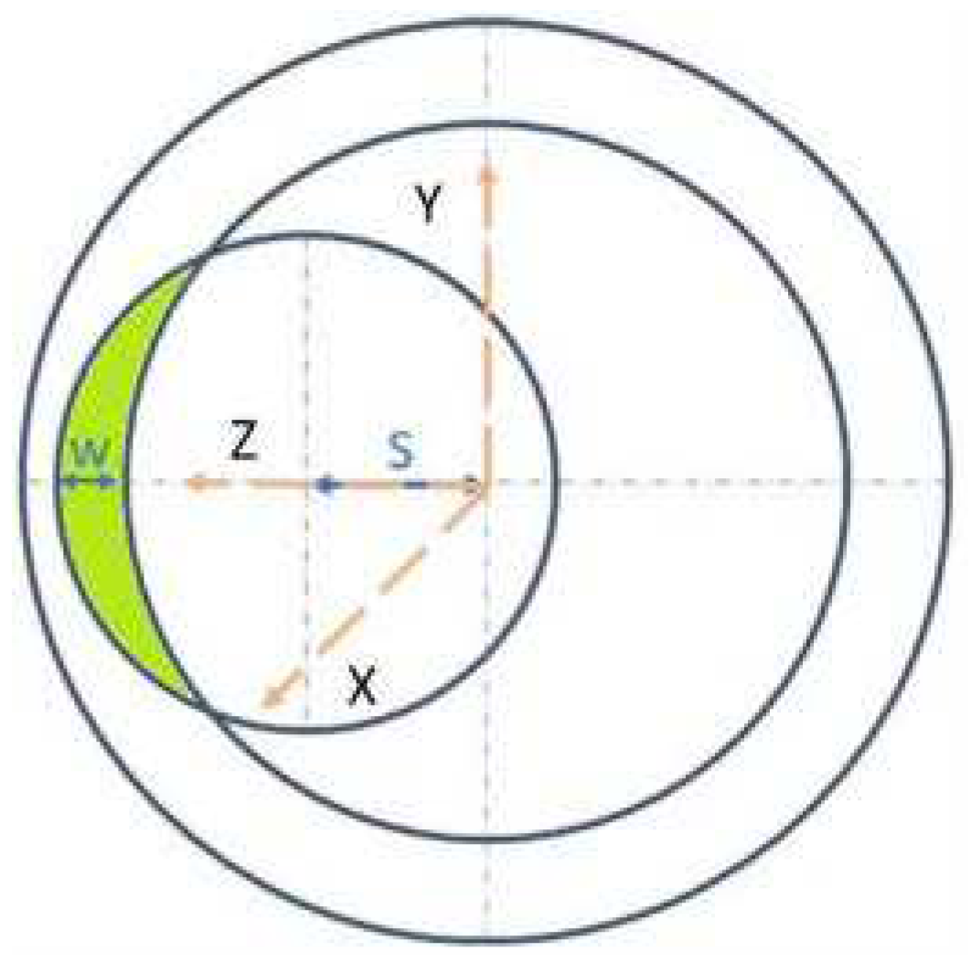
2.2. Characterization
3. Results and Discussions
3.1. Elemental Composition and Hardness Evaluation
3.2. Casing wear depth and volume
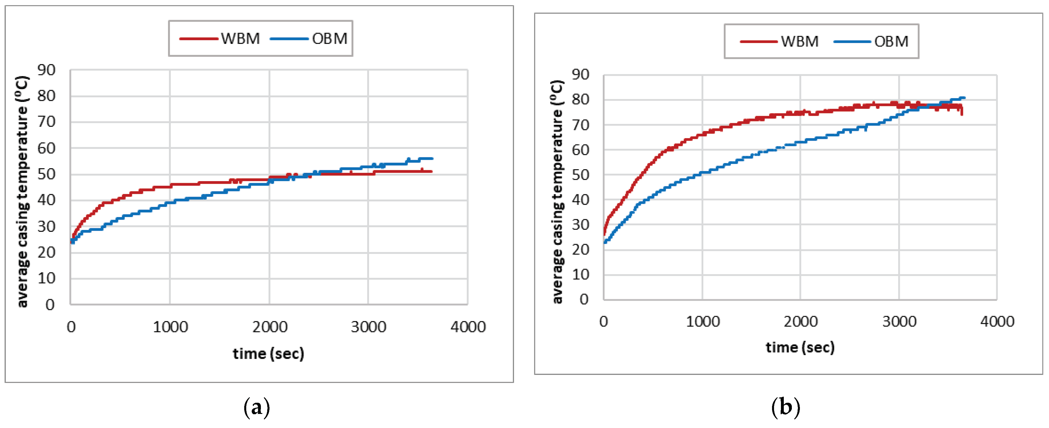
3.3. Specific wear factor of SM2535-110 casing
3.4. Drilling Mud Type Effect on Wear Factor
3.5. Wear mechanisms of SM2535-110 casing
4. Conclusions
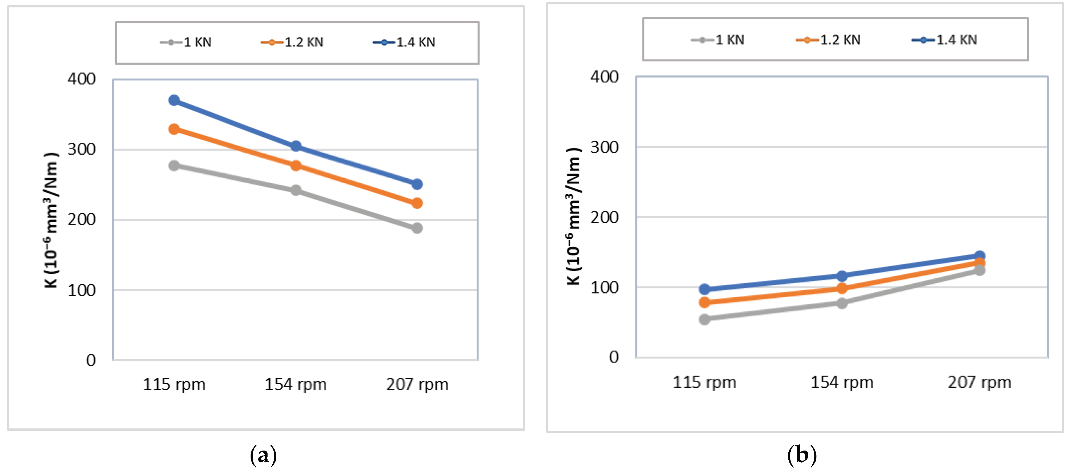
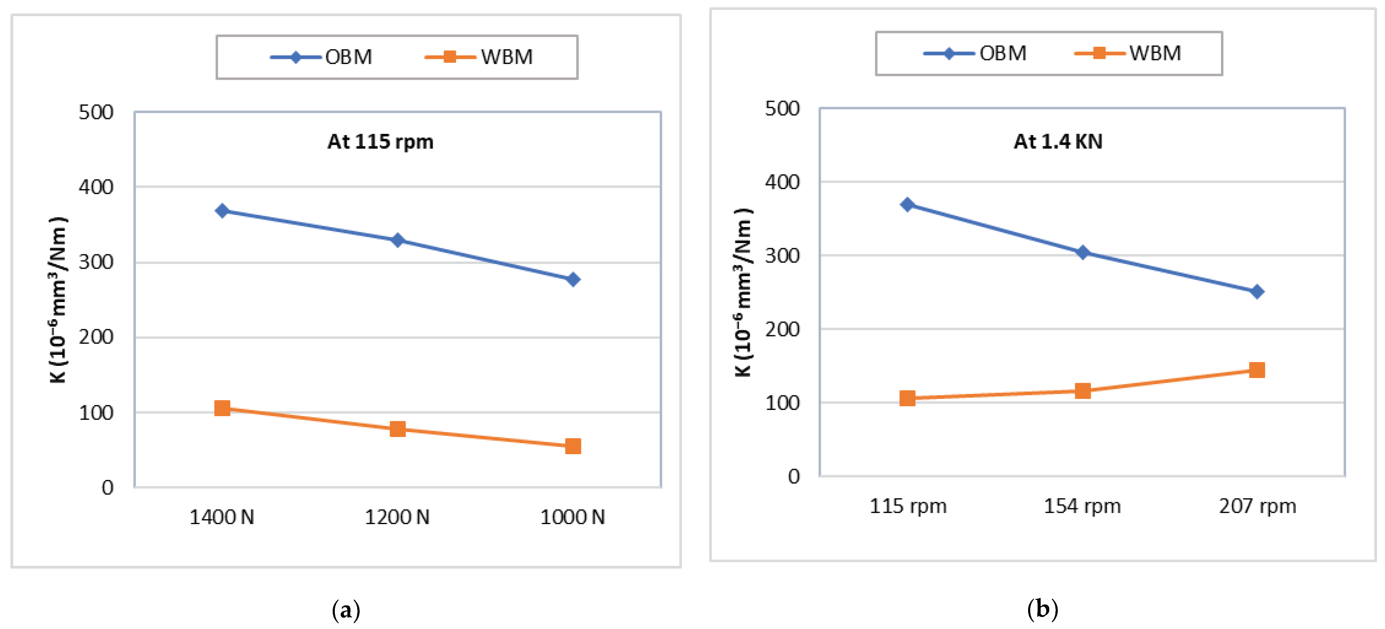
- Under both OBM and WBM, the specific wear factor increases with increasing side load due to the increase in the real area of contact.
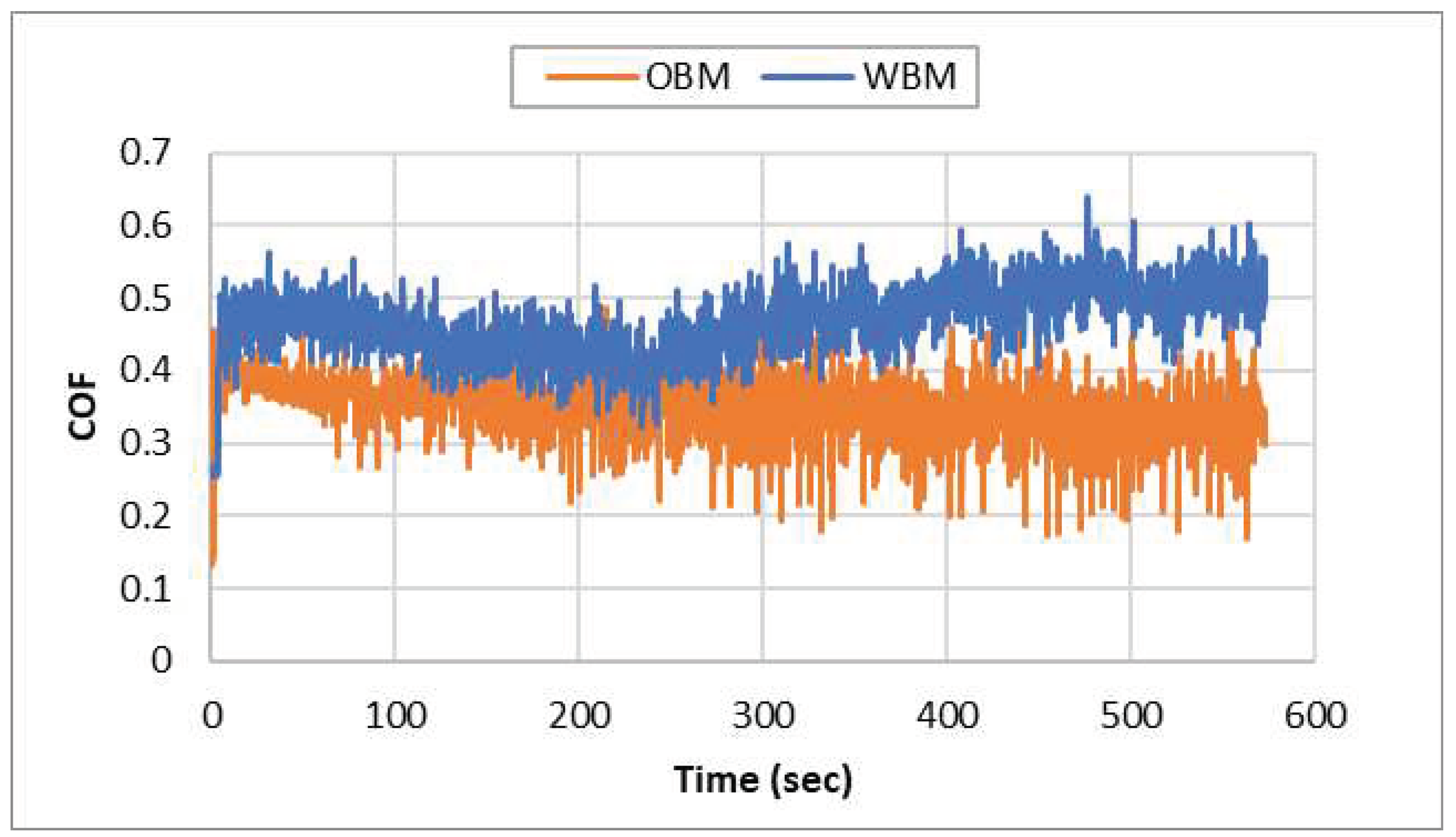
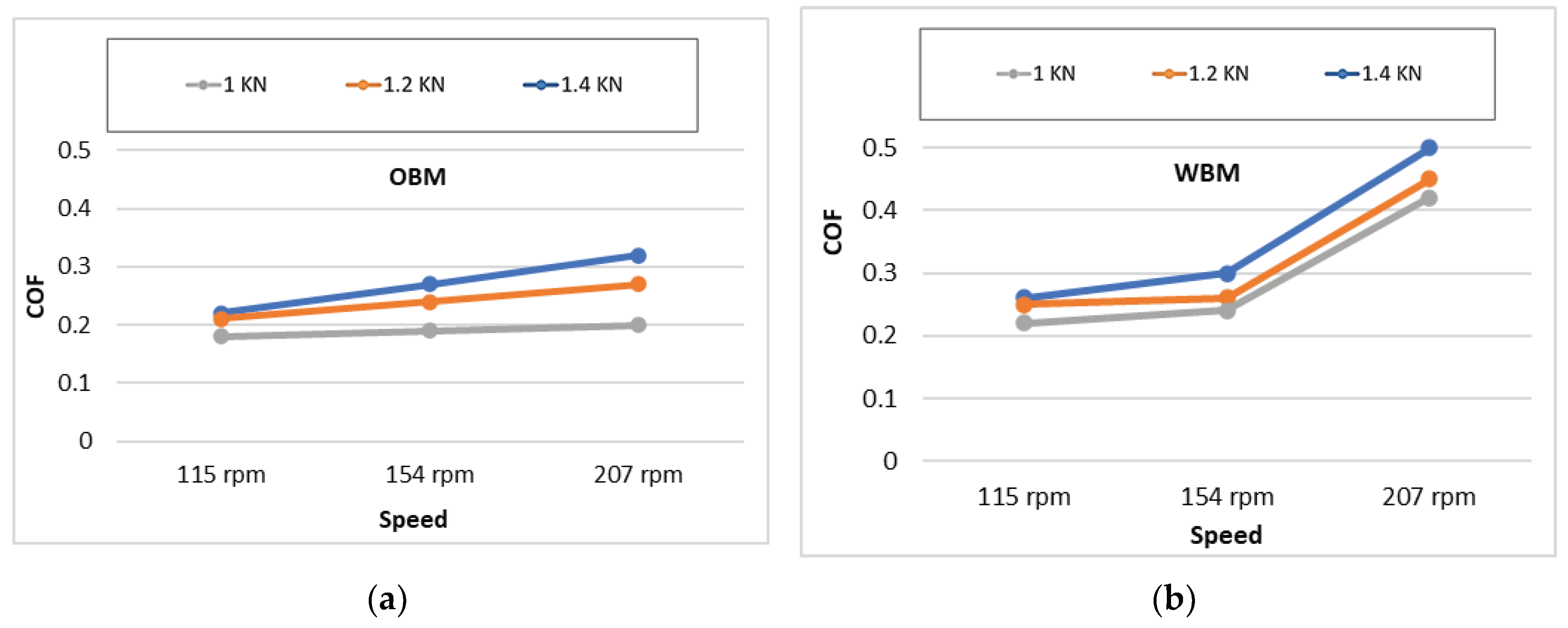
- The casing wear factor decreases with increasing rotational speed for specimens tested under OBM while it increases for specimens tested under WBM. The first is mainly due to the change in the lubrication regime from boundary to hydrodynamic lubrication at higher speeds, while the second is due to the lower viscosity of the WBM and the higher COF.
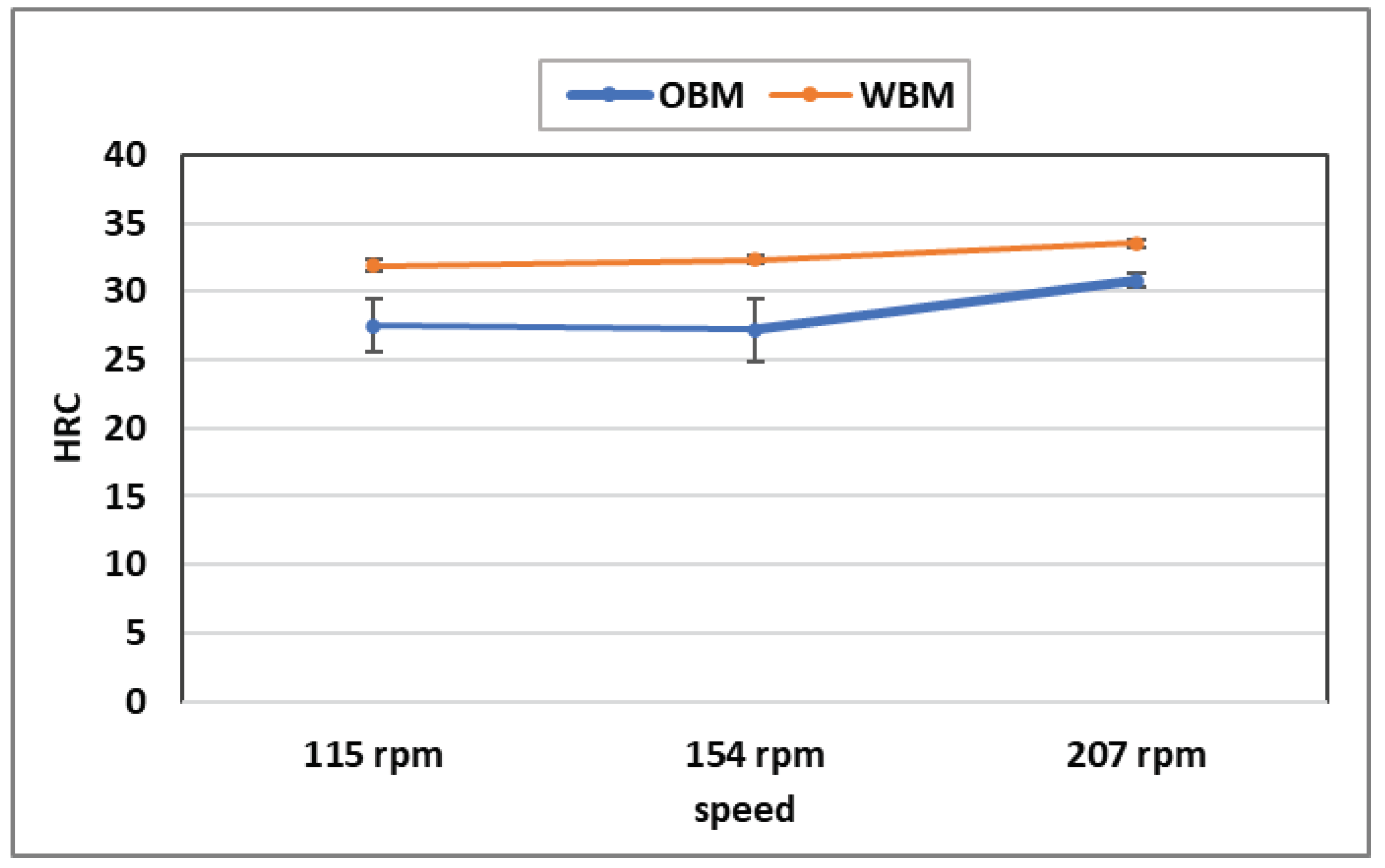
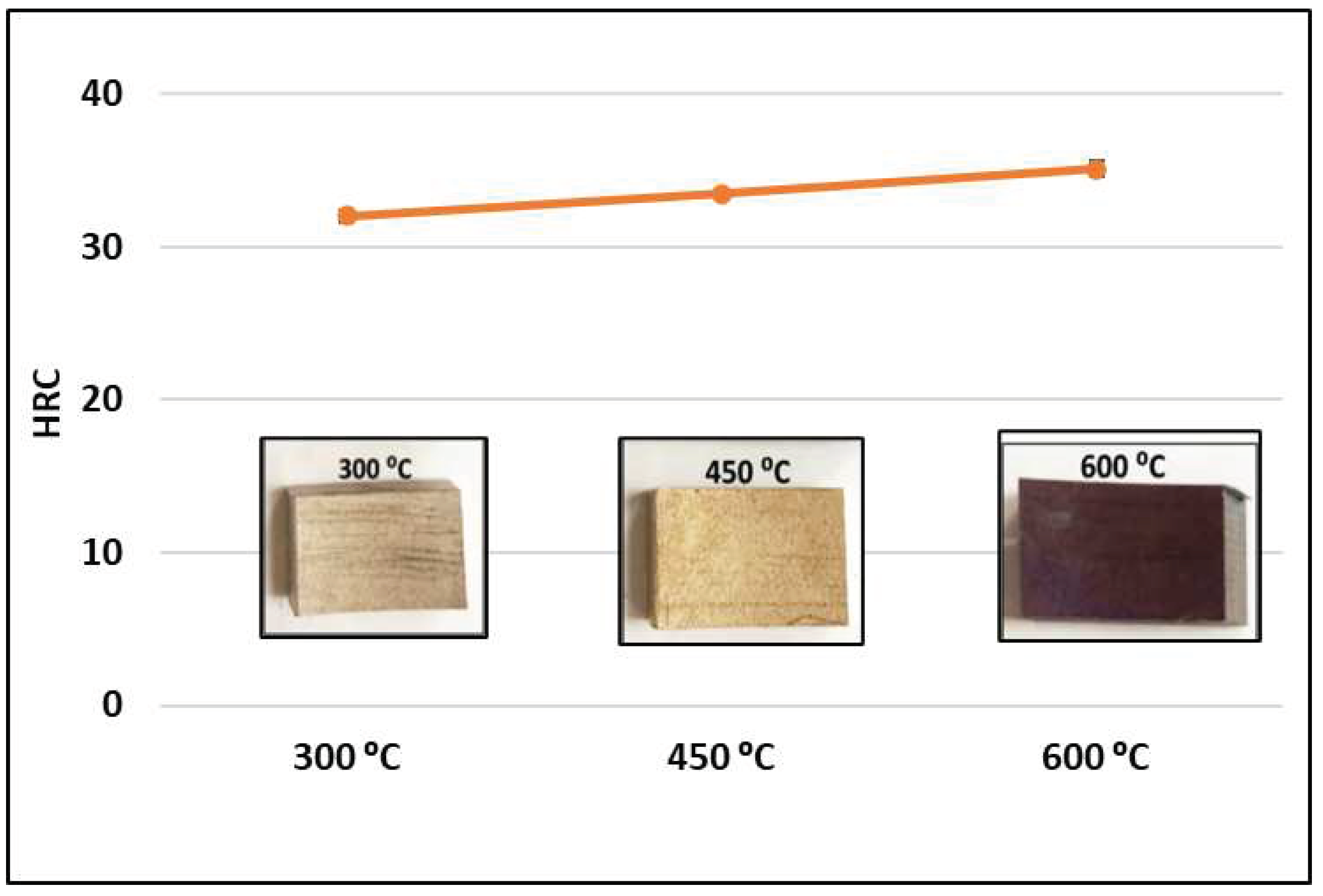
- The increase in surface hardness of specimens tested under WBM resulted in a lower specific wear factor compared to that obtained under OBM.
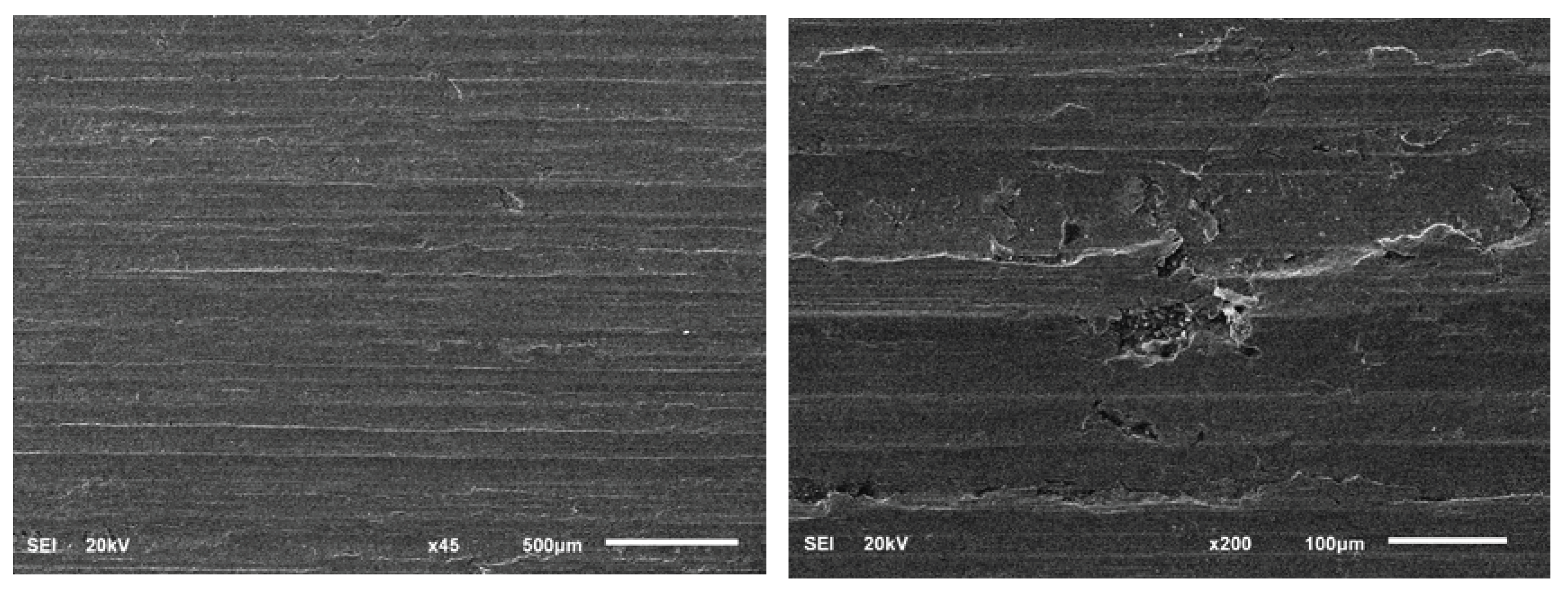
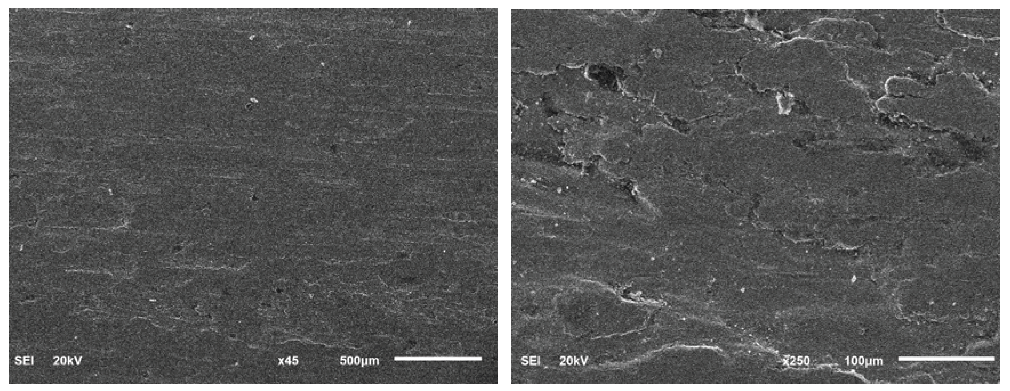
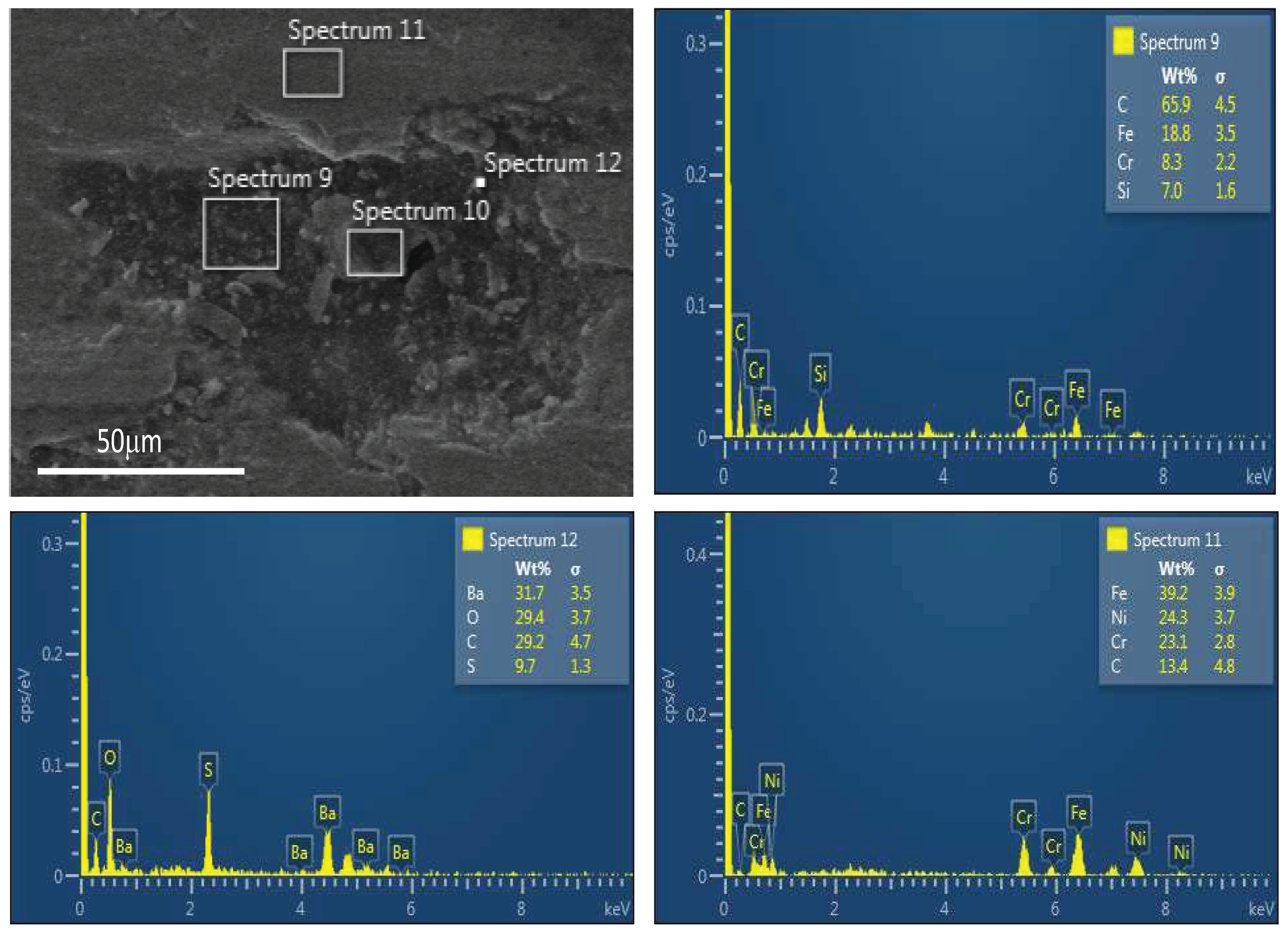
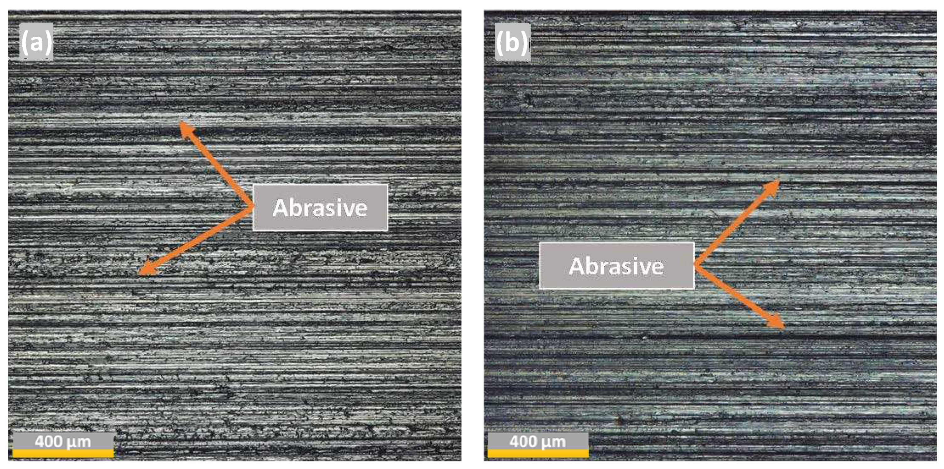
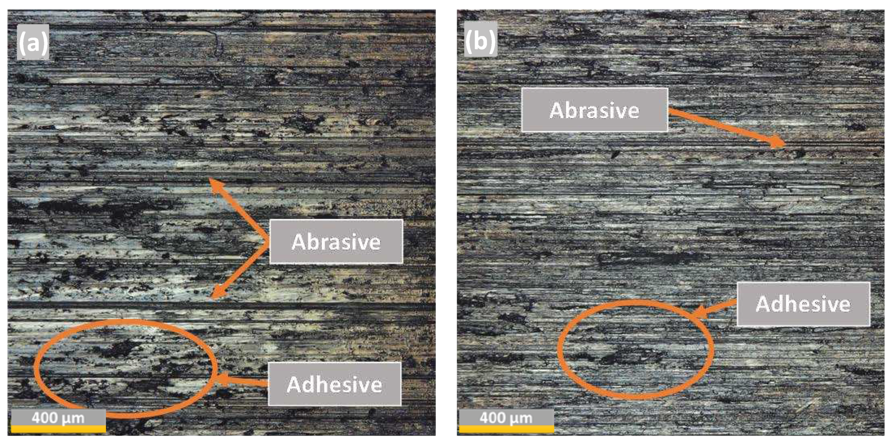
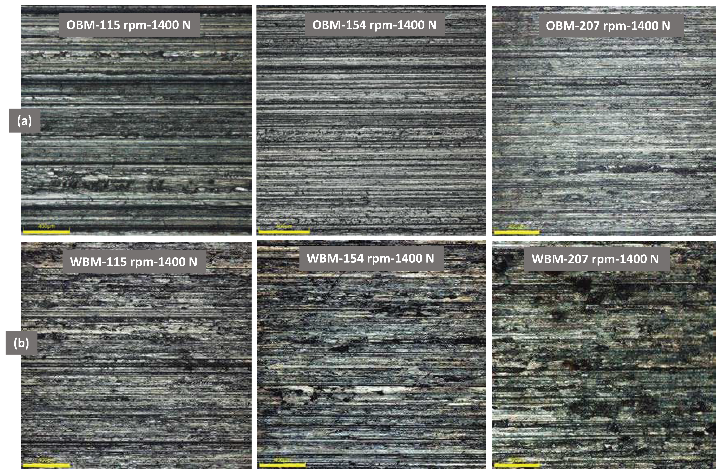
- The primary wear mechanism under OBM was abrasion, whereas the primary wear mechanism with WBM lubrication was adhesion and plastic deformation, especially at high side loads.
Author Contributions
Funding
Data Availability Statement
Acknowledgments
References
- Fischer, A. (Alfons); Bobzin, K. Friction, Wear and Wear Protection: International Symposium on Friction, Wear and Wear Protection 2008, Aachen, Germany; Wiley-VCH: 2009; ISBN 352732366X.
- Andersson, S. Wear Simulation with a Focus on Mild Wear in Rolling and Sliding Contacts. In Friction, Wear and Wear Protection; Wiley-VCH Verlag GmbH & Co. KGaA: Weinheim, Germany, 2011; pp. 1–19. [Google Scholar]
- Huimei, W.; Yishan, L. The Influence of Drilling Parameters on Casing Wear in Ultra-Deep Directional Well. In ICPTT 2012: Better Pipeline Infrastructure for a Better Life; 2013; pp. 920–926.
- Gao, D.; Sun, L.; Lian, J. Prediction of Casing Wear in Extended-Reach Drilling. Petroleum Science 2010, 7, 494–501. [Google Scholar] [CrossRef]
- Williamson, J.S. Casing Wear: The Effect of Contact Pressure. Journal of Petroleum Technology 1981, 33, 2382–2388. [Google Scholar] [CrossRef]
- Rădăcină, D.; Halafawi, M.; Avram, L. Casing Wear Prediction in Horizontal Wells. Petroleum and Coal 2020, 62, 395–405. [Google Scholar]
- Zhang, Q.; Lian, Z.; Lin, T.; Deng, Z.; Xu, D.; Gan, Q. Casing Wear Analysis Helps Verify the Feasibility of Gas Drilling in Directional Wells. Journal of Natural Gas Science and Engineering 2016, 35, 291–298. [Google Scholar] [CrossRef]
- Best, B. Casing Wear Caused by Tooljoint Hardfacing. SPE Drilling Engineering 1986, 1, 62–70. [Google Scholar] [CrossRef]
- Doering, A.E.R.; Danks, D.R.; Mahmoud, S.E.; Scott, J.L. Evaluation of Worn Tubulars from DEA-42 and Small-Scale Casing Wear Testers. In Proceedings of the Offshore Technology Conference; Offshore Technology Conference, 8 April 2011.
- Yu, H.; Lian, Z.; Lin, T.; Liu, Y.; Xu, X. Experimental and Numerical Study on Casing Wear in Highly Deviated Drilling for Oil and Gas. Advances in Mechanical Engineering 2016, 8, 1–15. [Google Scholar] [CrossRef]
- Chen, Y.; He, C.; Zhou, X.; Yu, H. Analysis of Factors Affecting Drilling Friction and Investigation of the Friction Reduction Tool in Horizontal Wells in Sichuan. Advances in Mechanical Engineering 2019, 11, 1–10. [Google Scholar] [CrossRef]
- Yu, H.; Lian, Z.; Lin, T.; Zhu, K. Experimental and Numerical Study on Casing Wear in a Directional Well under in Situ Stress for Oil and Gas Drilling. Journal of Natural Gas Science and Engineering 2016, 35, 986–996. [Google Scholar] [CrossRef]
- Osman, O.A.; Merah, N.; Samuel, R.; Alshalan, M.; Alshaarawi, A. Casing Wear Tests for Precise Wear Factor Evaluation. In Proceedings of the Paper presented at the IADC/SPE International Drilling Conference and Exhibition, Galveston, Texas, USA, March 2022; Vol. Day 1 Tue. [CrossRef]
- Osman, O.A.; Merah, N.; Abdul Samad, M.; Baig, M.M.A.; Samuel, R.; Alshalan, M.; Alshaarawi, A. Casing Wear and Wear Factors: New Experimental Study and Analysis. Materials 2022, 15. [Google Scholar] [CrossRef] [PubMed]
- Osman, O.; Merah, N.; Samad, M.; Baig, M.; Samuel, R.; Alshalan, M.; Alshaarawi, A. Wear Factors and Mechanisms of L-80 Steel Casings. Engineering Research Express 2023. [Google Scholar] [CrossRef]
- Sridhar, N.; Thodla, R.; Gui, F.; Cao, L.; Anderko, A. Corrosion-Resistant Alloy Testing and Selection for Oil and Gas Production. Corrosion Engineering, Science and Technology 2018, 53, 75–89. [Google Scholar] [CrossRef]
- Al-Saeedi, M.J.; Al-Enezi, D.; Sounderrajan, M.; Saxena, A.K.; Gumballi, G.K.; McKinnell, D.C. First Implementation of CRA Casing in Sour HPHT Reservoirs in Deep Wells in Kuwait. North Africa Technical Conference and Exhibition 2013, SPE-164603-MS.
- Li, L.F. Corrosion-Resistant Alloys for Tubings and Casings and Alloy Material Selection in Oil and Gas Wells. Advanced Materials Research 2013, 690–693, 276–279. [Google Scholar] [CrossRef]
- Nippon Steel Tubular Products. Available online: https://www.tubular.nipponsteel.com/octg-material/data-sheet/sm2535-110 (accessed on 23 November 2022).
- Moore, M.A. The Relationship between the Abrasive Wear Resistance, Hardness and Microstructure of Ferritic Materials. Wear 1974, 28, 59–68. [Google Scholar] [CrossRef]
- Stachowiak, G.W.; Batchelor, A.W. Introduction. In Engineering Tribology; Elsevier, 2006; pp. 1–9.
- API 5CT Chemical Composition of Casing Pipe. Available online: https://www.hu-steel.com/product89_991.html.
- Yaqoob, M.S.T. Empirical Analysis of Localized Casing Wear with Variations in Contact Pressure and Drilling Conditions. 2021.



| Elements | SM2535-110 | Drill Pipe | Counterface (DP-TJ) |
|---|---|---|---|
| Fe | 35.5% | 96.2% | 92.4% |
| C | 0.02% | 0.4% | 0.9 % |
| Cr | 25.7% | 1.4% | 3.8% |
| Ni | 32% | 0% | 0% |
| Mo | 4.1% | 0% | 0% |
| Mn | 0.7% | 0% | 0% |
| Casing property | unit | values |
|---|---|---|
| Ultimate tensile Strength value | (MPa) | ≥792 |
| Yield Strength value | (MPa) | 758-965 |
| Casing hardness Value | (HRC) | ≤33 |
| Outer DP Diameter | (mm) [in] | (245) [9 – 5/8] |
| Casing Thickness | (mm) [in] | (110) [0.44] |
| SM2535-110 | Drill Pipe | Counterface (DP-TJ) |
|
|---|---|---|---|
| Hardness | 31.73 ± 1.9 | 26.18 ± 1.5 | ± 0.8 |
| Type of mud | Sample number | Speed (rpm) | Side Load (N) | K (10−6 mm3/Nm) | |
|---|---|---|---|---|---|
| OBM | S1 | 115 | 1 K | 277.13 | |
| S2 | 115 | 1.2 K | 329.53 | ||
| S3 | 115 | 1.4 K | 369.52 | ||
| S4 | 154 | 1 K | 241.66 | ||
| S5 | 154 | 1.2 K | 277.42 | ||
| S6 | 154 | 1.4 K | 304.82 | ||
| S7 | 207 | 1 K | 188.38 | ||
| S8 | 207 | 1.2 K | 223.17 | ||
| S9 | 207 | 1.4 K | 251.06 | ||
| WBM | S10 | 115 | 1 K | 54.88 | |
| S11 | 115 | 1.2 K | 78.48 | ||
| S12 | 115 | 1.4 K | 106.27 | ||
| S13 | 154 | 1 K | 77.33 | ||
| S14 | 154 | 1.2 K | 98.12 | ||
| S15 | 154 | 1.4 K | 115.81 | ||
| S16 | 207 | 1 K | 124.05 | ||
| S17 | 207 | 1.2 K | 134.85 | ||
| S18 | 207 | 1.4 K | 144.4 |
Disclaimer/Publisher’s Note: The statements, opinions and data contained in all publications are solely those of the individual author(s) and contributor(s) and not of MDPI and/or the editor(s). MDPI and/or the editor(s) disclaim responsibility for any injury to people or property resulting from any ideas, methods, instructions or products referred to in the content. |
© 2023 by the authors. Licensee MDPI, Basel, Switzerland. This article is an open access article distributed under the terms and conditions of the Creative Commons Attribution (CC BY) license (http://creativecommons.org/licenses/by/4.0/).


