1. Introduction
The underground coal gasification (UCG) process leads to permanent structural changes in the coal seam and the surrounding rock mass resulting in the creation of a combustion zone with a combustion cavity and a fracture zone [
1,
2,
3,
4,
5,
6,
7]. Knowing the size and shape of the cavity is fundamental to UCG technology in terms of the efficiency of the method as well as its safety for the environment. Imaging these structural changes is complex due to the specific site conditions and, as a consequence, the unpredictable character of the development of the UCG process [
8]. The progression of the UCG process depends on complex physical and chemical processes, heat and mass transport, thermo-mechanical processes, water influx, and many geological factors, none of which can be observed directly [
5,
9].
The development of the combustion zone can be simulated by mathematical modelling and imaging by measurement methods, particularly those of a geophysical nature. Various geophysical techniques have been attempted in UCG processes in many countries through laboratory and experiments [
8,
10,
11,
12].
Su et al. [
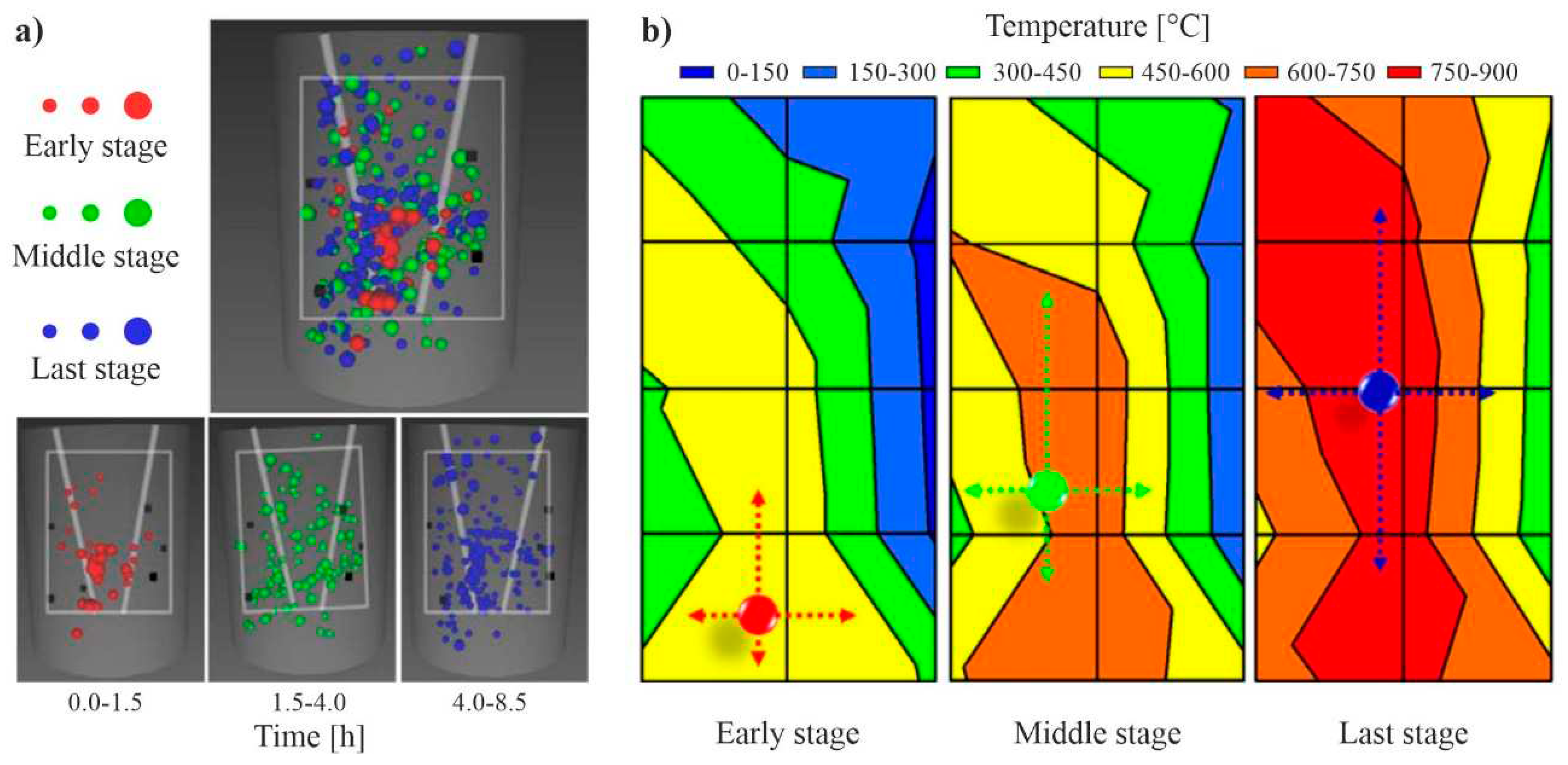
13] demonstrated an acoustic emission (AE) technique and X-ray computed tomography (CT) to monitor the development of the combustion zone in laboratory experiments in Japan. The appearance of many microcracks inside the coal block that was demonstrating AE activity with increases in temperature (
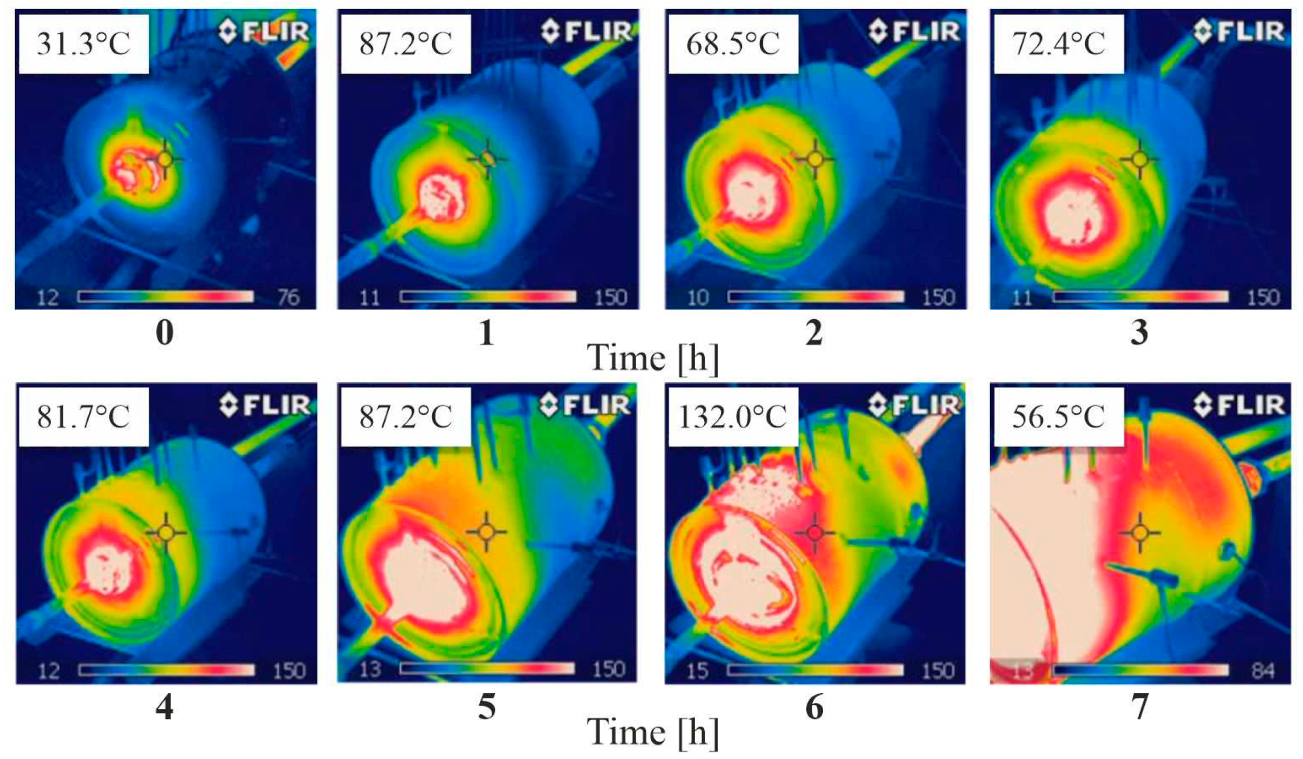
Figure 1). It was concluded that AE activity was induced by thermal stress. The location of the AE sources reflected the size of the combustion zone. The growth of the combustion zone in the coal block was also observed using thermography images.
Figure 2 shows the geometry of the combustion zone gradually and irregularly changing with changes in temperature. These laboratory experiments were later developed by Su et al. [
13,
14].
Ground-penetrating radar (GPR) was applied in a laboratory experiment concerning the imaging of the combustion zone in the coal block from Bełchatów opencast lignite mine, Poland [
11,
15,
16]. An antenna with a dominant frequency of 1 GHz was employed. The combustion zone was clearly visible after the termination of the process but was considerably less so during the gasification. Three zones could be distinguished inside the coal block during the gasification process: a zone of completely gasified lignite, a zone of partially gasified lignite, and a zone of partially thermally processed lignite.
Using geophysical methods on laboratory models, one can expect significant methodological limitations related to the model's dimensions. Khan et al. [
9] underlined the fact that the generalising data from these experiments should still be prepared with an appropriate level of care since the UCG process may not be fully represented in such experiments. However, in field experiments, geophysical observations of the combustion zone development is challenging due to measurement conditions and difficulties in installing measurement systems.
Over time, several geophysical techniques have shown great potential in field experiments using the UCG process. These include temperature measurements of different techniques, acoustic activity, electrical and electromagnetic methods, gravimetric method, seismic techniques and remote sensing techniques [
8,
11,
17,
18]. In the nineteen-thirties, early temperature observations in field-scale trials were performed in the Soviet Union and developed later in many countries [
6,
17,
19]. In the nineteen-seventies and nineteen-eighties, in early experiments in the United States, there was a practice of installing different kinds of detectors in monitoring boreholes that were not cost-effective [
8]. In the nineteen-seventies, Duba et al. [
10] reported that the high frequency electromagnetic (HFEM) imaging method, which located the position of the burn front to within 1 m, was used during the Hoe Creek II and III experiments in Wyoming [
8,
20]. This imaging system used HFEM radiation of 1MHz to 100 MHz between boreholes that were up to 25 m apart. During a UCG experiment in Centralia, Washington, cavity growth was monitored with thermocouples, time-domain reflectometry (TDR), and controlled source audio-magnetotelluric (CSAMT) [
21]. In general, cavity sizes measured during excavation were larger than estimated on the basis of instrumental data [
22] after [
8]. TDR measurements have provided primary evidence of the location of burn fronts [
20,
23]. Didwall and Dease [
24] reported that CSAMT does not offer a good resolution at depths of below 100m.
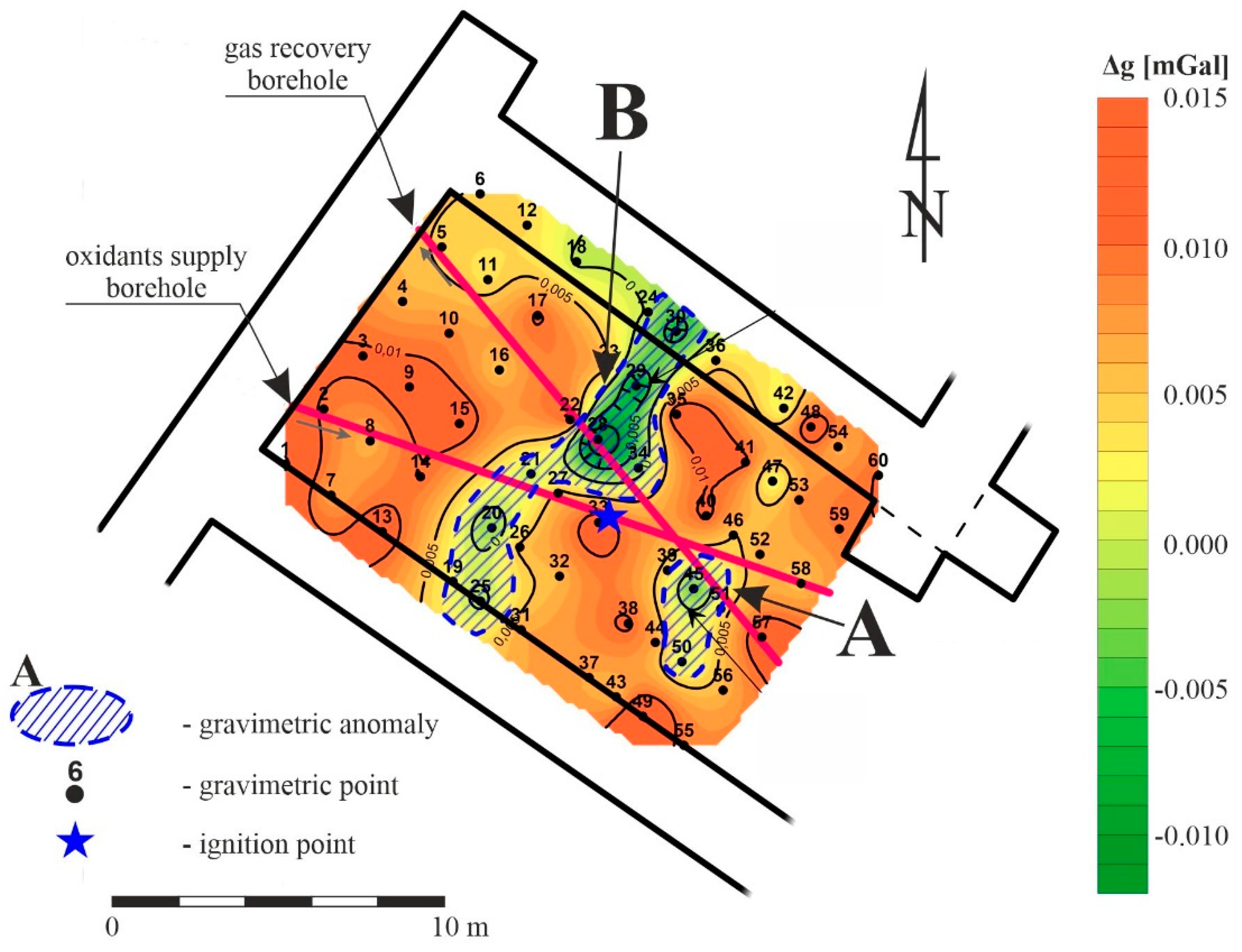
Kotyrba et al. [
18] studied the development of combustion cavity growth using the microgravimetric method. The measurements were conducted on the terrain surface over a UCG reactor in a shallow coal seam in a field experiment in the Central Mining Institute, Barbara Experimental Mine, Poland. Gravimetric anomalies have confirmed the effects of cavity growth. Small cavities have been identified by control boreholes in both A and B gravimetric anomalies, as shown in
Figure 3. It was underlined that in the case of coal seams located at deeper levels, it should be effective to conduct gravimetric measurements in workings located above the UCG reactor.
Kotyrba and Stańczyk [
11] also conducted GPR measurements to monitor the UCG process of the field experiment at Barbara Experimental Mine. GPR measurements were performed with a 100 MHz monostatic antenna, which revealed a tubular combustion cavity with carbonised coal with an approximate height of 0.8–1.0 m and a length of several meters in the coal seam. This structure corresponded to the image simulating the gasification growth based on modelling the amplitude of the reflected signals. They underlined the advantage of the GPR method due to its high resolution and the possibility of determining the spatial shape of various zones and formations created in the coal by the gasification process.
The possibilities for observing changes in the geometry combustion zone using other geophysical methods resulting from the development of methodology and measuring equipment should be emphasised. In particular, seismic interferometry [
25] and terrestrial laser scanning in observations of land surface deformations over various types of cavities [
26] should be mentioned.
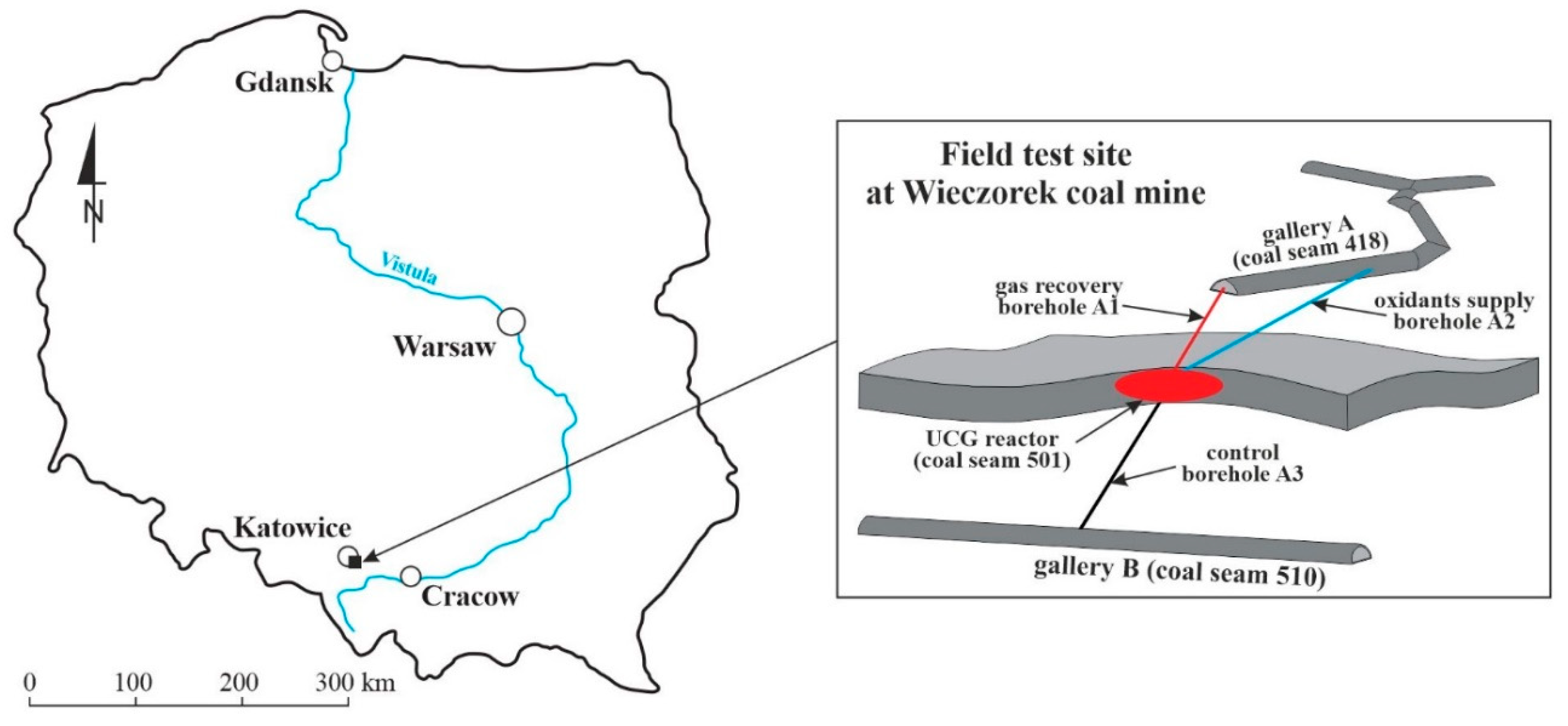
In this study, we present the results of borehole ground-penetrating radar (BGPR) measurements taken in control boreholes after UCG process termination to provide more detailed information about structural changes in the coal seam. The main aim of the research was to verify the efficiency of the BGPR technique in order to determine the geometry of the combustion cavity in specified geological conditions. The UCG field experiment was performed in the geological and mining conditions of the Wieczorek coal mine in the Upper Silesia Coal Basin in southern Poland (
Figure 4). The BGPR tests were performed on three boreholes, approximately 40-50 m long and drilled six months after the termination of the UCG process. In this article, the authors present the geological and technological conditions of the field-scale experiment, the methodology employed, the results of the BGPR measurements and a discussion on the effectiveness of this method.
2. Materials and Methods
2.1. Geological and technological conditions
The UCG field experiment was performed in coal seam 501 in the active Wieczorek coal mine at a depth of approximately 460 m [
27,
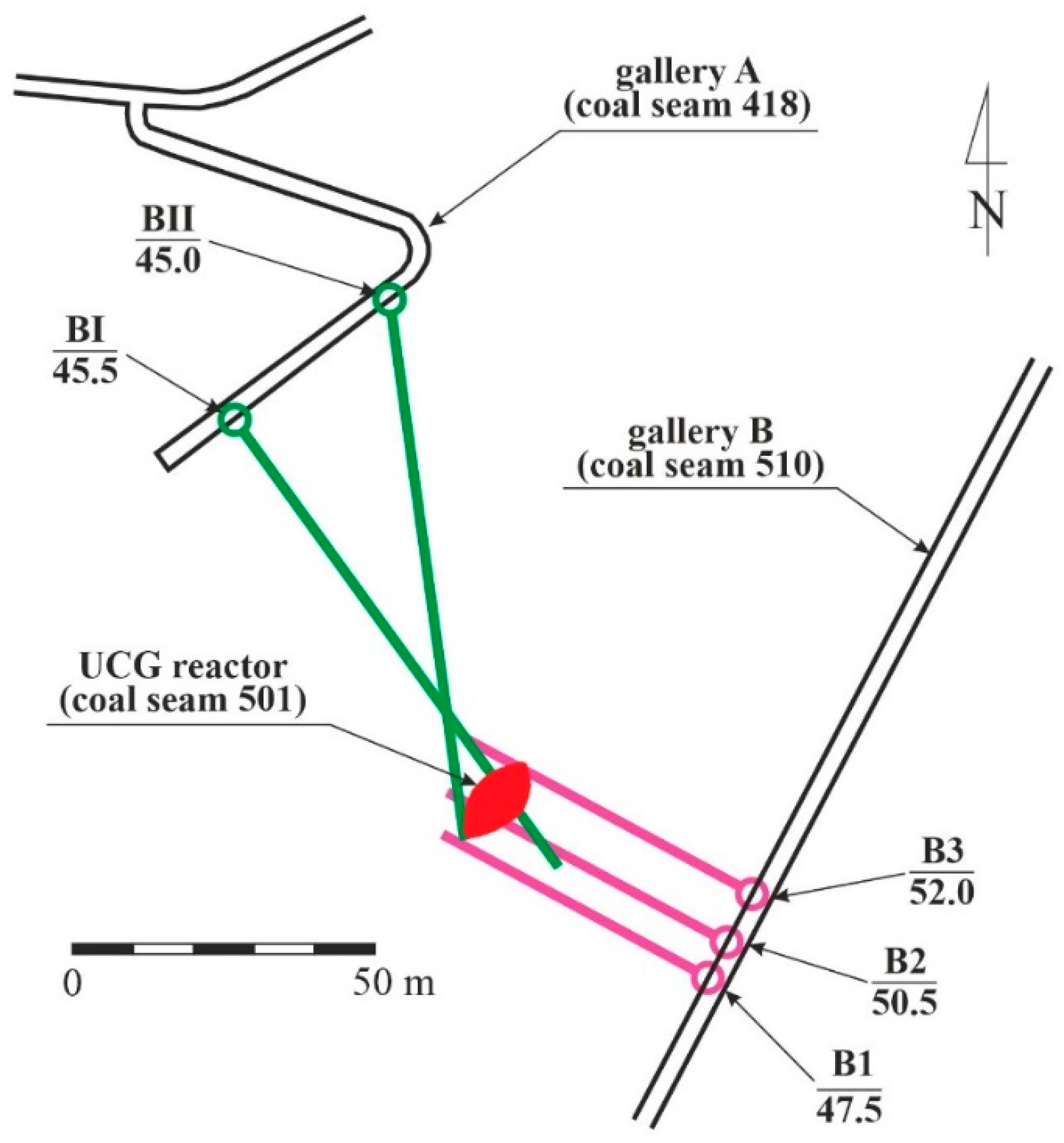
28]. The UCG process was ignited in coal seam 501 below gallery A in coal seam 418 and above gallery B in coal seam 510 (
Figure 4). From gallery A, borehole A1 was made for receiving syngas and borehole A2 was for oxidants supplied to the UCG reactor. From channel B, borehole A3 was drilled to control the UCG process. The gasification process lasted two months. Access to the excavations located in the area of the UCG reactor was obtained approximately six months after its termination. The UCG process is presented in more detail by Mocek et al. [
27].
Coal seam 501 is approximately 5.3 m thick with an inclination of about 6° SE. The rock mass overlying coal seam 501 is mainly composed of low-permeability mudstone and sandstone. At the bottom of coal seam 501 there are also layers of mudstone and sandstone. About 26 m deeper, there is coal seam 510, which is around 8 m thick.
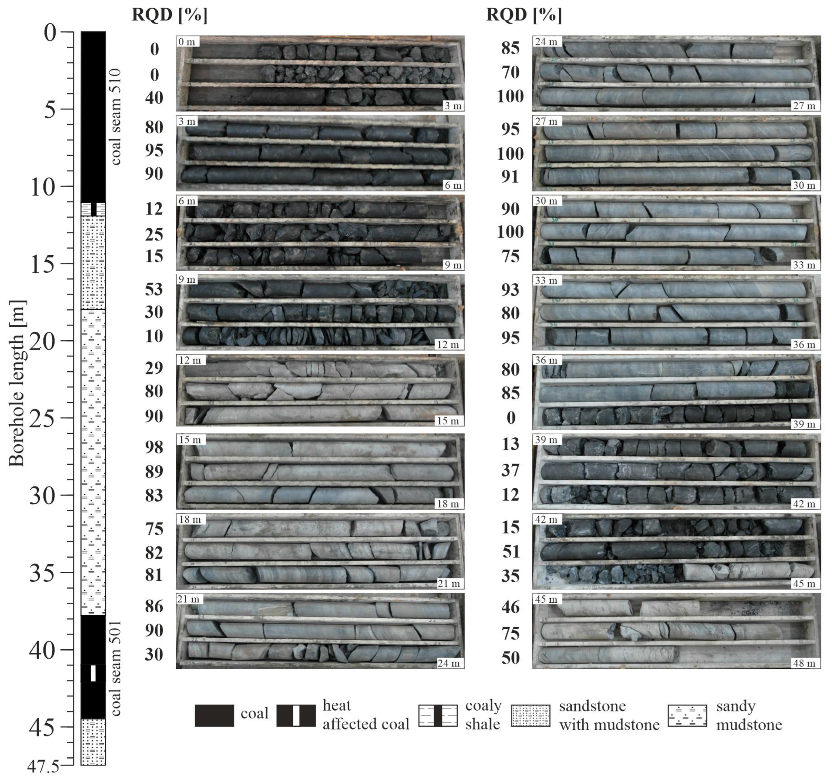
Figure 5 shows an example of a geological profile from the B1 borehole with the core and the calculated RQD. This borehole was drilled from gallery B to coal seam 510 towards the UCG reactor after its termination. In the section from 35.0 m to 35.5 m of the drill core, intense carbonisation of the coal fragments in coal seam 501 is observed. Both coal seams 501 and 510 show fairly strong fractures. The average RQD for coal seam 510 is 40, and for the coal seam 501, it is 20, indicating an increase in fracturing near the UCG reactor. Rocks such as mudstones, sandstones, and shales accompanying the coal seams are much less fractured, and the average RQD is about 80. Long-term exploitation of the coal seams in the area of the planned experiment had a significant impact on the rock mass fracturing [
27]. This resulted in the drying of the rock mass in the area of the UCG reactor location.
2.1. Methodology
Having terminated the UCG process, five additional coring boreholes were drilled (
Figure 6) in order to identify the geometry of the resulting combustion cavity and the impact of the UCG process on the surrounding rocks [
28]. Two boreholes were drilled from gallery A, and the remaining three boreholes were executed from gallery B. The directions of the boreholes were chosen in order to intersect the combustion zone. In all boreholes, RQD tests with macroscopic core analyses were performed. In the B1 and B3 boreholes, coal samples from the combustion zone were taken to determine V
daf, the volatile matter, by the gravimetric method according to [
29] and C
daf carbon content according to [
30]. Attempts to observe the walls of the boreholes with an endoscopic probe did not provide additional information due to the large amount of coal dust.
BGPR measurements were taken in the B1, B2 and B3 control boreholes (
Table 1), which were made from gallery B.
The BGPR investigation consisted of several main stages:
a comprehensive review of archival reports on UCG reactor location and functionality;
BGPR measurement design;
BGPR measurements, data processing and interpretation;
integrated analysis of georadar data and borehole data with accompanying tests for determination of the geometry of the combustion cavity.
BGPR measurements were conducted with a 100 MHz antenna using the reflection technique. The acquisition parameters are presented in
Table 2. A dipole antenna was used, which radiates and receives reflected signals omnidirectionally for 360
o. This technique cannot precisely determine the azimuth of reflecting objects – distance from the reflectors can only be assumed. The distance in the borehole was recorded using measuring wheels mounted on the tripod installed in gallery B.
Due to the construction of the probe, the measurement was limited at the end of the borehole. The probe consisted of two basic parts - a transmitter (Tx) with a length of 1.89 m and a receiver (Rx) with a length of 1.76 m, separated by a pipe separator with a length of 1.0 m. Such a construction did not enable the obtaining of a georadar image at approximately 2.0 m from the end of the hole.
The GPR data was processed using standard procedures with the ReflexW [
31] software. The processing workflow applied to the BGPR data was typical for this type of research (e.g. [
32]. This included: data input, time t0 correction, removal of the wowing effect (subtract-mean dewow), direct current (D.C.) removal, bandpass frequency filtration, 1D median filtering, gain function with the use of an energy decay filter and background removal. To eliminate possible low-frequency components, the subtract-mean dewow filter was used. Additionally, D.C. removal was used to eliminate offsets in the data by subtracting the mean of the last 26% of GPR traces. Median trace removal along each line was performed to eliminate the direct wave and significant ringing in the data. After testing, automatic gain control was avoided in order to enable the relative comparisons of the reflectivity of the investigated objects. Instead, the gain function with an energy decay filter was used. The GPR signals were vertically stacked thirty-two times during acquisition for the purposes of enhancing the signal-to-noise ratio. The applied procedures have been widely presented by [
33].
The radargrams are presented in the form of two-dimensional images. The radargram's horizontal axis are determined on a distance scale, whereas the vertical axis has a time scale.
3. Results and discussion
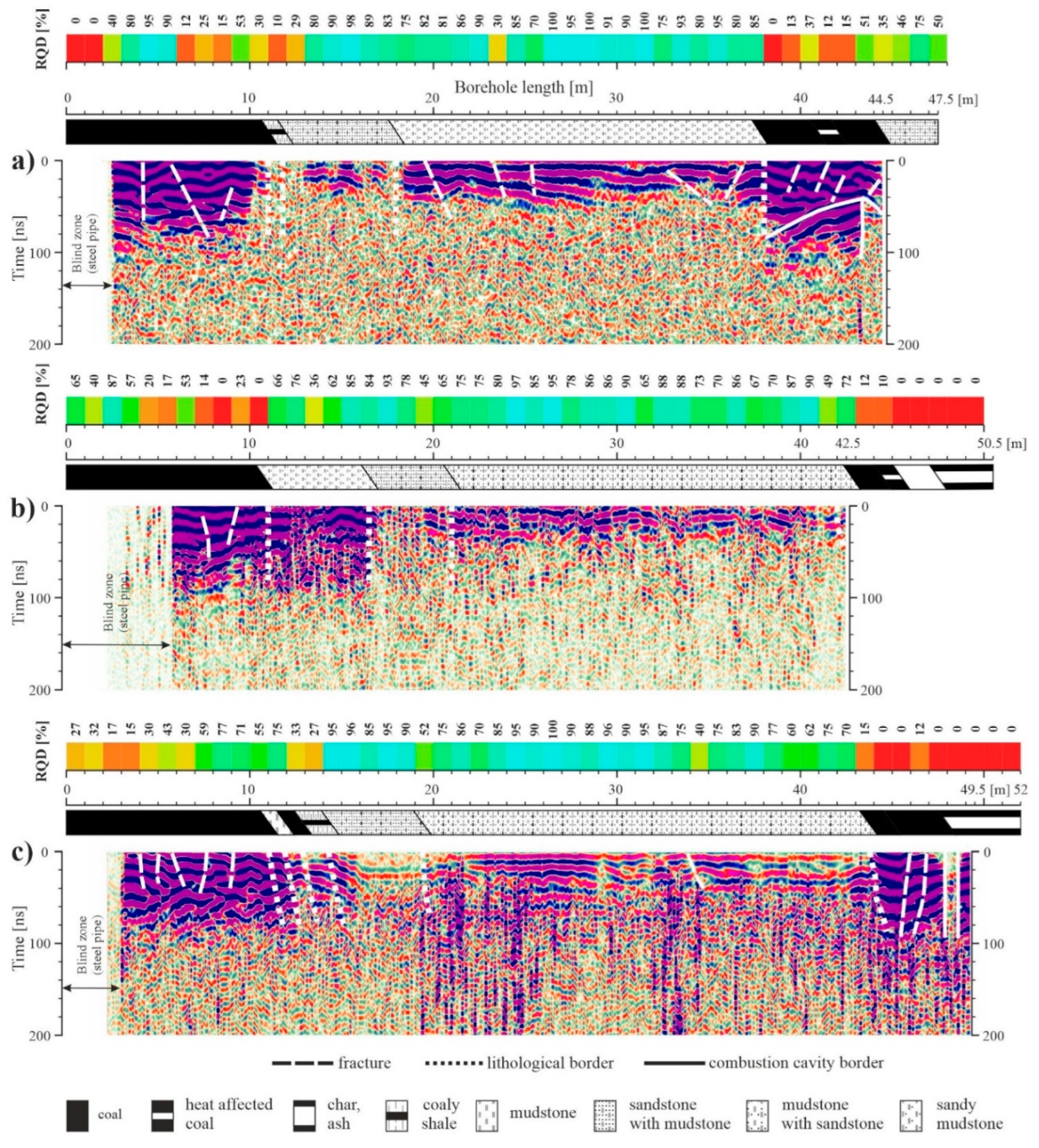
The radargrams obtained from BGPR measurements in the B1, B2 and B3 boreholes are shown in
Figure 7. The useful signal from the 100 MHz antenna reached a penetration depth around the borehole of up to approx. 3-4 m in carboniferous rock formations and approx. 5-6 m in the coal seam. The radargrams were almost identical regardless of whether the probe was pushed into or pulled out of the boreholes.
The radargram from borehole B1 was developed up to 44.5 m (
Figure 7a). The initial 3 m of the borehole is illegible in the image due to the steel casing pipe protecting the inlet of the borehole. In the section up to approx. 11 m, coal seam 510 is marked, followed by coaly shale up to approx. 12 m. Sandstone with varying degrees of interbedded mudstone occurs up to 18 m. In the next section of the borehole, up to approx. 38 m, there is mudstone with sandstone. Larger cracks are visible in this section. Coal seam 501 is marked from approx. 38 m to the end of the radargram to 44.5 m. It is strongly fractured. The control borehole was drilled to a length of 48 m, extending to approximately 3.5 m into the sandstone and mudstone layer. This borehole did not go through a combustion cavity, but it should be assumed that it passed through a fracture zone around the cavity.
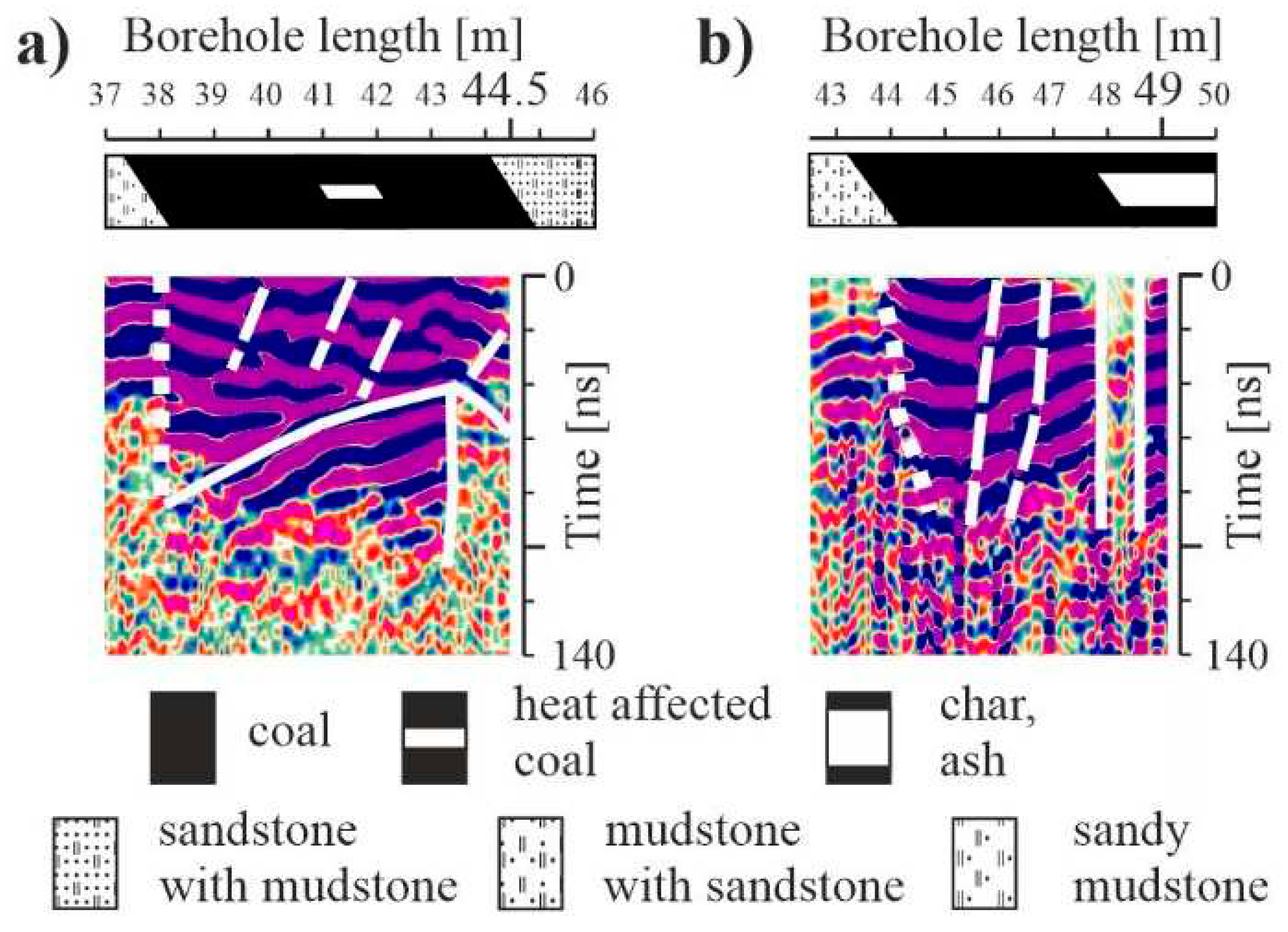
In the georadar image, a combustion cavity is visible at a distance of approximately 2.5 m from the borehole in the section from approx. 38 to 44.5 m (
Figure 7a and
Figure 8a). In the upper part of the cavity, a layer of sandstone with mudstone is marked, which indicates the burning of coal seam 501 into the roof part.
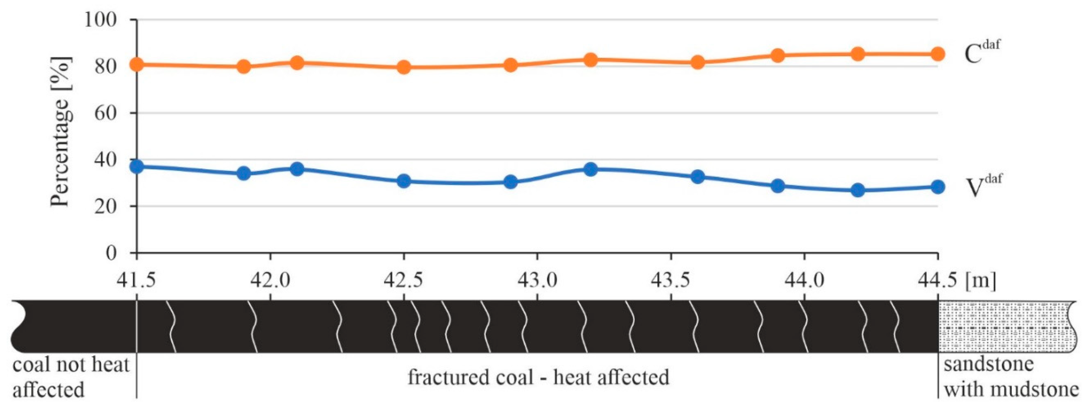
Laboratory tests of coal samples taken from the core of the B1 borehole indicate its small transformation (Hildebrandt, 2017). The values of the content of volatile matter V
daf and the carbon content C
daf show low percentage changes (
Figure 9). The value of V
daf for comparison taken at 43.6 m was 32.62%, and C
daf - 81.69%. With the increase in borehole length up to the top of seam 501 at 44.5 m, the value of C
daf increased to 85.17%, while V
daf decreased to 28.35%. The temperature influence in the roof part of seam 501 caused these changes. The macroscopic analysis of the core confirmed more intensified coal fractures in the section from 41.5 m to 44.5 m.
Laboratory tests of coal samples taken from the core of the B1 borehole indicate its small transformation [
28]. The radargram from borehole B2 covered up to 42.5 m of the borehole length (
Figure 7b). Deeper penetration of the probe into the borehole was impossible due to the dried coal, char, ash and rock fragments occurring in the floor of the combustion cavity. The initial 6 m of the borehole is illegible due to the steel casing pipe protecting the inlet of the borehole. In the section up to approx. 11 m, coal seam 510 is marked out, followed by a mudstone layer up to approx. 17 m. In the next borehole section, up to approx. 21 m, sandstone with mudstone is present, and there is then mudstone with sandstone up to approx. 42.0 m. In the end part of the radargram, at about 42 m, coal seam 501 is fragmentarily visible. Next, the borehole entered the combustion cavity floor filled with coal gasification products. No accompanying tests were performed in the B2 borehole.
The radargram from the B3 borehole covered up to 49.5 m of the borehole length (
Figure 7c). As before, the initial 3 m of the borehole is illegible due to the steel casing pipe protecting the inlet to the borehole. In the borehole section up to approx. 11 m, coal seam 510 is marked out, followed by layers of mudstone, coal and coaly shale up to 14.5 m. In the next section, up to approx. 19.5 m, there is predominantly sandstone with mudstone, then predominantly mudstone with sandstone up to 43.5 m. Next, coal seam 501 is marked out, in which a combustion cavity fragment is present in the section from about 48 m to about 49 m (
Figure 7c and
Figure 8b). This cavity fragment has a cross-sectional shape similar to a triangle, indicating the combustion cavity's end section. Coal seam 501 is marked again in the final fragment of the radargram, which is approximately 0.5 m long. This means that coal seam 501 in the area of the B3 borehole has not been burnt down to the roof rock layer.
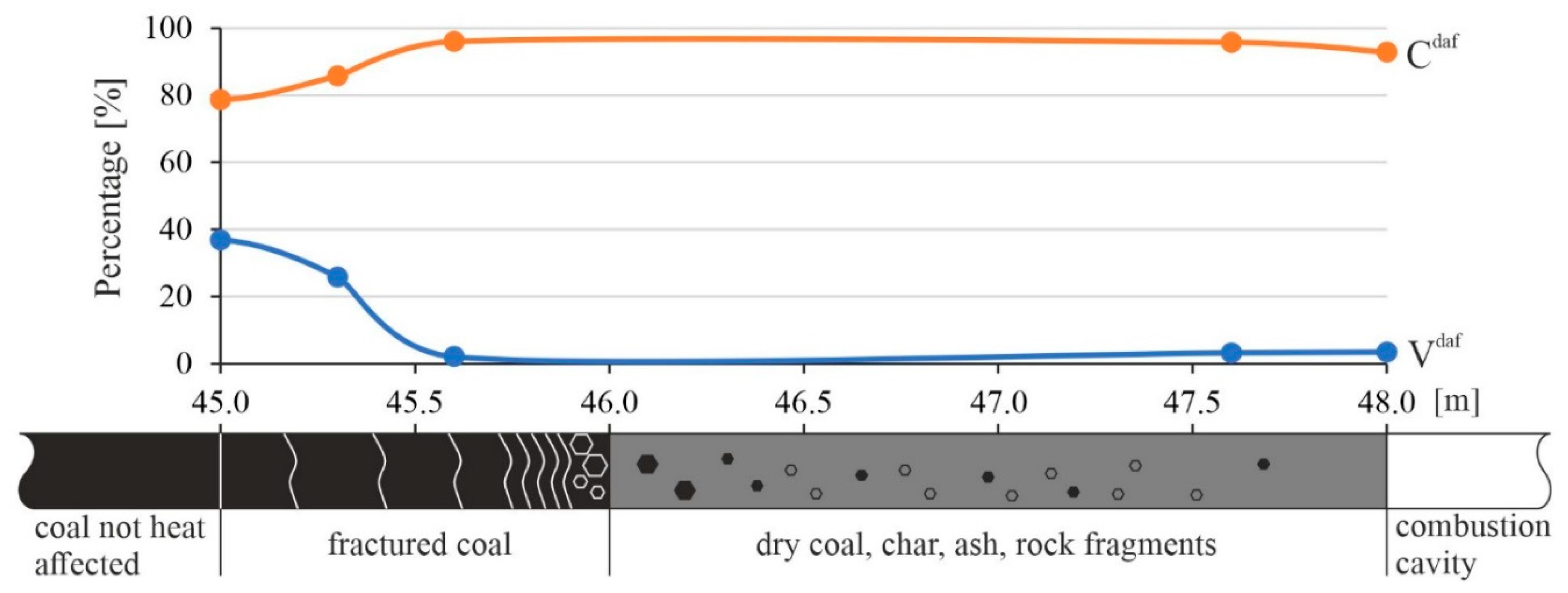
The coal seam 501 transformation process was visible in the coal samples taken from the core from borehole B3 (
Figure 10). In particular, a significant change in the values of C
daf and V
daf was observed in the section from 45 to 45.6 m. From 46 to 48 m, dry coal, char, ash and rock fragments were observed.
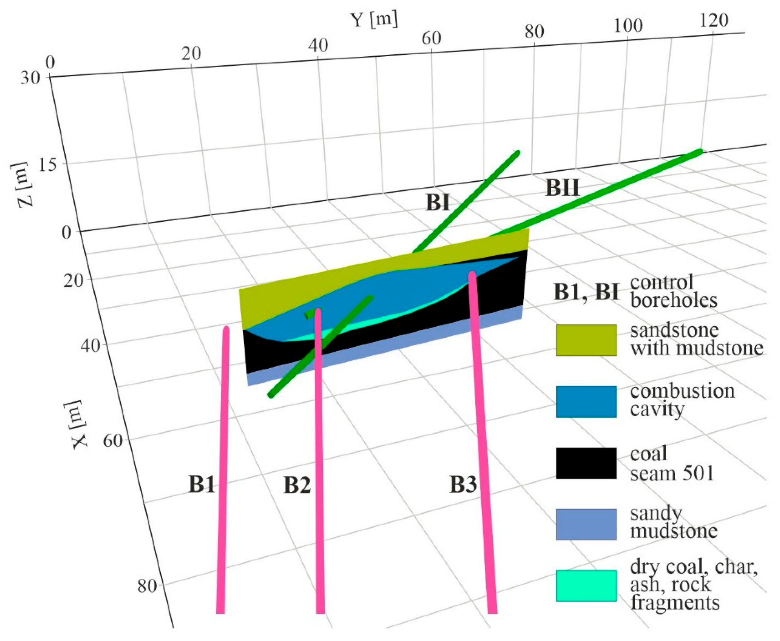
Based on data obtained from the drilling of all test boreholes, borehole georadar tests and accompanying tests, the geometry of the combustion cavity was determined.
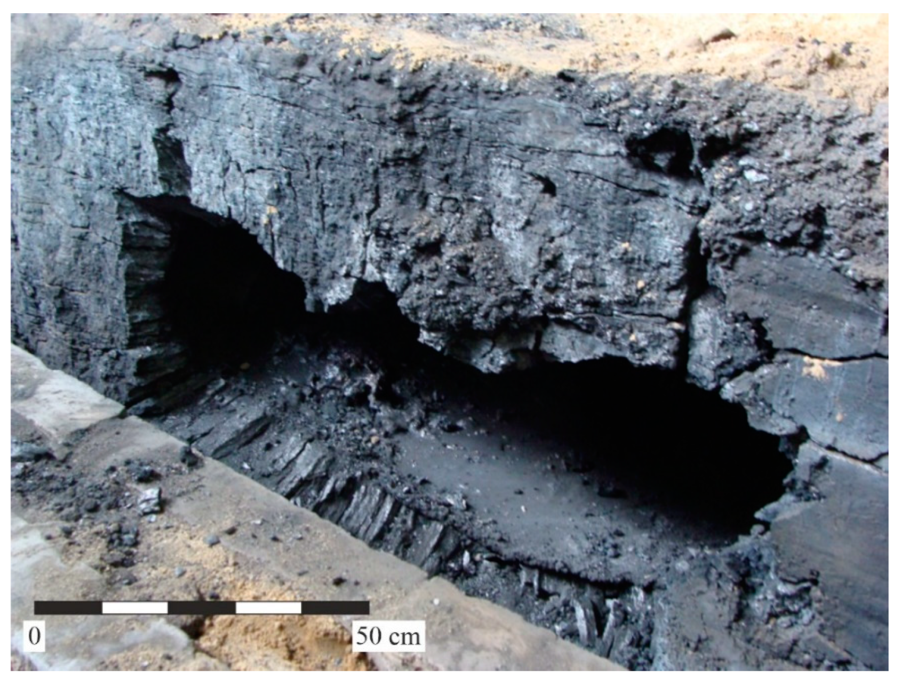
Figure 11 shows the geometry of this cavity along with the locations of the test boreholes. The shape of the cavity in the cross section perpendicular to gasified coal seam 501 had the shape of a distorted, inverted trapezoid and was similar to the cavity created in the laboratory experiment at Barbara Experimental Mine [
4,
15] (
Figure 12).
The gasification zone was estimated to have covered coal seam 501 with an area of approx. 90 m
2 [
27]. The cavity had a length of around 32 m, a width of around 7 m (measured in the plane of coal seam 501) and a height of around 5 m (measured perpendicularly to the plane of the coal seam 501). The cavity had the largest volume in the roof of coal seam 501 and decreased towards its floor. In the floor part of the cavity there were dry coal, char, ash and fragments of rocks from the roof layer which changed to varying temperature. Such cavity filling is consistent with numerous observations (e.g. [
6]). A zone of fractures was created around the cavity, which is clearly noticeable in coal seam 501.
Different zones of different attenuation of electromagnetic wave energy propagating in Carboniferous rock layers and coal seams are visible on the radargrams. The attenuation is weaker in coal seams and mudstones and stronger in sandstones. The determined electromagnetic boundaries come from larger fractures, lithological changes and the interface between the transformed coal and the cavity. It should be emphasised that the radargram from the B1 borehole shows the boundaries of the cavity which were not visible in the borehole (
Figure 7a). Larger cracks in the coal seam can be distinguished on the radargrams. However, the boundaries between transformed coal and non-transformed coal, observed by Kotyrba and Stańczyk [
11], were not visible. Presumably, this was due to the lower resolution of the 100 MHz antenna compared to the 1 GHz antenna. Larger fractures were fairly well visible in the sandstone, as in
Figure 7. The fractures in the mudstones were barely visible. However, the lithological boundaries between the sandstone, mudstone and coal seam layers were marked as their dielectric constants differed significantly.
It should be emphasised that the georadar survey provided additional data for the borehole survey, which enabled a more accurate determination of the combustion cavity of the UCG reactor. One should agree with Kotyrba and Stańczyk [
11] that the advantage of the GPR method is its high resolution and the possibility of determining the spatial shape of various zones created in the coal seam and surrounding rock layers by the gasification process.
4. Conclusions
The efficiency of the underground coal gasification (UCG) process depends on the possibility of the precise imaging of the development of the gasification zone. Various methods can be used for the determination of the geometry of the combustion cavity. The basic techniques are exploratory drilling, but they require more boreholes to be drilled. However, various geophysical methods can be useful as a control technique. Among these, one option is use of the borehole ground penetrating radar method. This method enables the imaging of different electromagnetic borders in a rock mass with distinct contrast in its electromagnetic properties.
This study showed the possibilities of detailing the boundaries of the combustion cavity created during underground coal gasification processes using BGPR. The experiment was performed in the conditions of the Wieczorek coal mine in the Upper Silesian Coal Basin after the termination of the UCG reactor. The results of the research enable the following conclusions to be drawn:
In the vicinity of control borehole B1, a combustion cavity was identified in coal seam 501 at approximately 2.5 m from the borehole. Macroscopic analysis of the core from the borehole only indicated more intense coal fractures in this section.
In borehole B3, the location of a fragment of a combustion cavity with maximum dimensions of approx. 1 m was confirmed in the roof section of coal seam 501. The cavity was also determined with a control borehole, but its shape was detailed on a georadar image.
Under the conditions of the BGPR tests, it was possible to use a 100 MHz antenna to distinguish larger cracks in the coal seams, thus determining the range of this zone. However, the boundary between transformed coal and non-transformed coal, observed by Kotyrba and Stańczyk [
11], was not marked.
Fractures were quite evident in the coal and sandstone, as is shown in
Figure 7. In mudstones, the fractures were barely visible. However, lithological interfaces are marked between coal seams, sandstone and mudstone layers.
In the case of a borehole passing through a cavern, borehole GPR measurements are strongly hindered, as dry coal, char, ash, and rock fragments are obstacles to the probe's movement. Borehole georadar measurements near the UCG of the reactor are possible after its termination due to the influence of high temperatures.
In the study, the borehole georadar has proven its efficiency in determining the borders of a combustion cavity with a fracture zone in the gasified coal seam. The obtained results are interesting and encourage further research of this type.
Author Contributions
Conceptualization, Z.P., R.H., Z.L., and E.P.; methodology, Z.P., R.H., K.K., and Z.L.; software, K.K., and T. Ł.; validation, E.P.; formal analysis, R.H.; investigation, K.K., R.H., and T.Ł.; resources, R.H., and Z.L.; data curation, K.K.; writing—Z.P., R.H., and K.K.; original draft preparation, K.K., and T. Ł.; writing—review and editing, Z.P., R.H., T.Ł., and Z.L.; visualization, R.H., and K.K.; supervision, Z.P., and R.H.; project administration, R.H., and Z.L.; All authors have read and agreed to the published version of the manuscript.
Funding
This research received no external funding.
Acknowledgments
The research was performed as a part of the project "Advanced technologies of energy generation", research task "Elaboration of coal gasification technology for highly efficient production of fuels and electricity", financed by the Polish National Centre for Research and Development under contract no. SP/E/3/7708/10.
Conflicts of Interest
The authors declare no conflict of interest.
References
- Britten, J.A.; Thorsness, C.B. A model for cavity growth and resource recovery during underground coal gasification. In Situ 1989, 13, 1–53. [Google Scholar]
- Alexander, Y.K. Early ideas in underground coal gasification and their evolution. Energies 2009, 2, 456–476. [Google Scholar]
- Shafirovich, E.; Varma, A. Underground Coal Gasification: A Brief Review of Current Status. Ind. Eng. Chem. Res. 2009, 48, 7865–7875. [Google Scholar] [CrossRef]
- Stańczyk, K.; Kapusta, K.; Wiatowski, M.; Świądrowski, J.; Smoliński, A.; Rogut, J.; Kotyrba, A. Experimental simulation of hard coal underground gasification for hydrogen production. Fuel 2012, 91, 40–50. [Google Scholar] [CrossRef]
- Bhutto, A.W.; Bazmi, A.A.; Zahedi, G. Underground coal gasification. From fundamentals to applications. Prog Energy Combust Sci 2013, 39, 189–214. [Google Scholar] [CrossRef]
- Perkins, G. Underground coal gasification_Part I: Field demonstrations and process performance. Progress in Energy and Combustion Science 2018, 67, 158–187. [Google Scholar] [CrossRef]
- Camp, D.W. A Review of Underground Coal Gasification Research and Development in the United States, Lawrence Livermore National Laboratory, LLNL-TR-733952, 2017.
- Mellors, R.; Yang, X.; White, J.A.; Ramirez, A.; Wagoner, J.; Camp, D.W. Advanced geophysical underground coal gasification monitoring. Mitig Adapt Strateg Glob Change 2016, 21, 487–500. [Google Scholar] [CrossRef]
- Khan, M.M.; Mmbaga, J.P.; Shirazi, A.S.; Trivedi, J.; Liu, Q.; Gupta, R. Modelling Underground Coal Gasification—A Review. Energies 2015, 8, 12603–12668. [Google Scholar] [CrossRef]
- Duba, A.; Davis, D.T.; Laine, E.F.; Lytle, R.J. Geotomography and coal gasification, Lawrence Livermore National Laboratory, UCRL- 81923, 1978.
- Kotyrba, A.; Stańczyk, K. Sensing underground coal gasification by ground penetrating radar. Acta Geophys. 2017, 65, 1185–1196. [Google Scholar] [CrossRef]
- Su, F.-Q.; Wu, J.-B.; Zhang, T.; Deng, Q.-C.; Yu, Y.-H.; Hamanaka, A.; Dai, M.-J.; Yang, J.-N.; He, X.-L. Study on the monitoring method of cavity growth in underground coal gasification under laboratory conditions. Energy 2023, 263, art126048. [Google Scholar] [CrossRef]
- Su, F.-Q.; Nakanowataru, T.; Itakura, K.-I.; Ohga, K.; Deguchi, G. Evaluation of Structural Changes in the Coal Specimen Heating Process and UCG Model Experiments for Developing Efficient UCG Systems. Energies 2013, 6, 2386–2406. [Google Scholar] [CrossRef]
- Su, F.-Q.; Itakura, K.-I.; Deguchi, G.; Koutarou, O. Monitoring of coal fracturing in underground coal gasification by acoustic emission techniques. Applied Energy 2017, 189, 142–156. [Google Scholar] [CrossRef]
- Stańczyk, K.; Smolinski, A.; Kapusta, K.; Świądrowski, J.; Wiatowski, M.; Kotyrba, A.; Rogut, J. Dynamic experimental simulation of hydrogen oriented underground gasification of lignite. Fuel 2010, 89, 3307–3314. [Google Scholar] [CrossRef]
- Kotyrba, A.; Stańczyk, K. Application of a GPR technique for monitoring simulated underground coal gasification in a large scale model. Near Surf Geophys 2013, 11, 505–515. [Google Scholar] [CrossRef]
- Yang, X.; Wagoner, J.; Ramirez, A. Monitoring of Underground Coal Gasification, Lawrence Livermore National Laboratory, LLNL-TR-578172, 2012.
- Kotyrba, A.; Kortas, Ł.; Stańczyk, K. Imaging the underground coal gasification zone by microgravity surveys. Acta Geophys 2015, 63, 634–651. [Google Scholar] [CrossRef]
- Xiao, Y.; Yin, J.; Hu, Y.; Wang, J.; Yin, H.; Qi, H. Monitoring and Control in Underground Coal Gasification: Current Research Status and Future Perspective. Sustainability 2019, 11, 217. [Google Scholar] [CrossRef]
- Yang, X.; Wagoner, J.; Ramirez, A.; Hunter, S.; Mellors, R.; Camp, D.; Friedmann, S.J.; Chen, F. Electrical resistance tomography for monitoring of underground coal gasification. In Proceedings of the International Pittsburgh Coal Conference, Lawrence Livermore National Laboratory, LLNL-CONF-493143. Pittsburgh, PA, USA, 12–15 September 2011. [Google Scholar]
- Cena, R.J.; Hill, R.W.; Stephens, D.R.; Thorsness, C.B. The Centralia partial seam CRIP underground coal gasification experiment, Lawrence Livermore National Laboratory, UCRL-91252, 1984.
- Wilder, D.G.; Ramirez, A.; Hill, R.W. Overview of the cavity mapping exercise, large block test, Centralia, Washington, Lawrence Livermore National Laboratory, Report UCRL-87529, 1982.
- Metzger, G.A. Preliminary time domain reflectometer results of the Rocky Mountain 1 coal gasification, Lawrence Livermore National Laboratory Report, 1988.
- Didwall, E.M.; Dease, C.G. Numerical and experimental results for detection of underground voids using controlled source electromagnetic technique, Lawrence Livermore National Laboratory, UCRL- 88968, 1983.
- Czarny, R.; Marcak, H.; Nakata, N.; Pilecki, Z.; Isakow, Z. Monitoring Velocity Changes Caused By Underground Coal Mining Using Seismic Noise. Pure and Applied Geophysics 2016, 173, 1907–1916. [Google Scholar] [CrossRef]
- Pilecka, E.; Szwarkowski, D. An application of ground laser scanning to recognise terrain surface deformation over a shallowly located underground excavation. E3S Web of Conferences 2017, 24, 01006. [Google Scholar] [CrossRef]
- Mocek, P.; Pieszczek, M.; Świądrowski, J.; Kapusta, K.; Wiatowski, M.; Stańczyk, K. Pilot-scale underground coal gasification (UCG) experiment in an operating Mine "Wieczorek" in Poland. Energy 2016, 111, 313–321. [Google Scholar] [CrossRef]
- Hildebrandt, R. A comprehensive method for assessing the effects of underground coal gasification. Ph.D. Thesis, (In Polish). The Central Mining Institute, Katowice, 2017. [Google Scholar]
- PN-G-04516:1998. Solid fuels. Determination of the volatile matter by gravimetric method. (In Polish).
- PN-G-04571:1998. Solid fuels. Determination of carbon, hydrogen and nitrogen contents using automated analysers. (In Polish).
- Reflexw v. 9.5 user's guide, 2018.
- Pilecki, Z.; Krawiec, K.; Pilecka, E.; Kotyrba, A.; Tomecka-Suchoń, S.; Łątka, T. Identification of buried historical mineshaft using ground-penetrating radar. Engineering Geology 2021, 294, art106400. [Google Scholar] [CrossRef]
- Annan, A.P. Practical Processing of GPR Data, Sensor and Software Inc., Canada, 1999.
|
Disclaimer/Publisher’s Note: The statements, opinions and data contained in all publications are solely those of the individual author(s) and contributor(s) and not of MDPI and/or the editor(s). MDPI and/or the editor(s) disclaim responsibility for any injury to people or property resulting from any ideas, methods, instructions or products referred to in the content. |
© 2023 by the authors. Licensee MDPI, Basel, Switzerland. This article is an open access article distributed under the terms and conditions of the Creative Commons Attribution (CC BY) license (http://creativecommons.org/licenses/by/4.0/).
