1. Introduction
The seedling plant factory enables the production of high-quality crops with consistent yields through precise control of the environmental conditions. The internal air environment plays a crucial role in the growth, yield, and quality of crops, particularly in the cultivation of seedlings[
1]. Temperature and humidity uniformity are key factors influencing crop yield [
2,
3,
4,
5,
6]. Achieving uniformity in the internal air environment is essential for effective management in plant factories, as uniform growth and high quality by development of automated systems.
By implementing precise control measures, plant factories can artificially create a favorable internal air environment and improve environmental uniformity such as temperature, humidity, and CO
2 affecting to seedling growth[
6]. The use of artificial lighting and specialized air conditioning facilities enables the production of high-quality crops with consistent yields throughout the year, overcoming seasonal limitations [
7,
8,
9,
10,
11,
12]. In seedling plant factory, production uniformity is crucial to maximize profits by ensuring consistent production, adopting an "all in, all out" approach can reduce labor requirements and decrease production time.
In plant factories, it is crucial to study the airflow as a means of environmental control. In order to make cultivation system including artificial lighting and specialized air conditioning facilities, significant initial investment and maintenance costs are required. To maximize profits per unit area in the seedling plant factory, multi-layer cultivation is a method of growing crops by stacking multiple levels of growth trays or shelves[
13,
14]. However, in the multi-layer cultivation, establishing a stable air flow with thermal uniformity becomes challenging due to the narrow spacing between growth shelves and the complexity of the structure. Therefore, research addressing the internal environmental uniformity in plant factories is crucial [
2,
3,
4,
15,
16,
17]. Studies on the aerodynamic approaches of plant factories have been conducted to enhance productivity through structural analysis [
18]. Internal environmental uniformity has been analyzed to improve the stable crop productivity through the uniformity of air distribution and temperature and humidity in a fully controlled plant factory [
19]. In the crop cultivation, the optimal air velocity range was suggested by 0.1 to 0.5 m/s resulting in enhancing product quality and preventing the occurrence of tip-burning phenomena[
20].
Computational fluid dynamics (CFD) serves as an effective tool for analyzing the uniformity of the internal air environment in controlled indoor plant factories. Using CFD models to perform aerodynamic analysis based on various structures and monitoring points can help identify issues within the internal environment and develop solutions to improve environmental uniformity [
18,
21,
22,
23]. Incorporating CFD into the analysis of plant factory environments enhances our ability to optimize efficiency and achieve a more uniform atmospheric environment[
24,
25,
26,
27,
28,
29].
A porous-panel type air exhaust system has shown promise in improving the uniformity of the internal air environment in plant factories. This system involves replacing the entire wall on one side with porous panels to facilitate exhaust ventilation in order to improve internal environmental uniformity. However, there are challenges associated with monitoring and analyzing the effect of porous-panel systems. Due to the low air velocity and limited space for environmental monitoring, it can be challenging to use conventional equipment for measurements. Additionally, the presence of measurement devices may interfere with the internal airflow. However, CFD can be used as an excellent tool for fluid-dynamically interpreting the effects of porous panels, such as fluid flow and the distribution of temperature and humidity. In the process of calculating the CFD model for the greenhouse, the crops were assumed as porous media for analysis [
30,
31]. Also, the aerodynamic impact of the insect screens used at the greenhouse entrance was analyzed with CFD, applying the concept of a porous surface[
32,
33,
34]
The purpose of this study is to monitor the uniformity of the internal environment of the seedling house using the porous panel exhaust system, and to analyze additional uniformity improvement measures using a CFD model. Through field monitoring at various locations, we have analyzed the uniformity of temperature and humidity, and developed and validated a CFD model for the same structure based on field data. Using the validated model, we have examined the need for additional ventilation and fluid dynamic improvements in the seedling house through CFD analysis considering various ventilation structures.
2. Materials and Methods
2.1. The experimental seedling plant factory
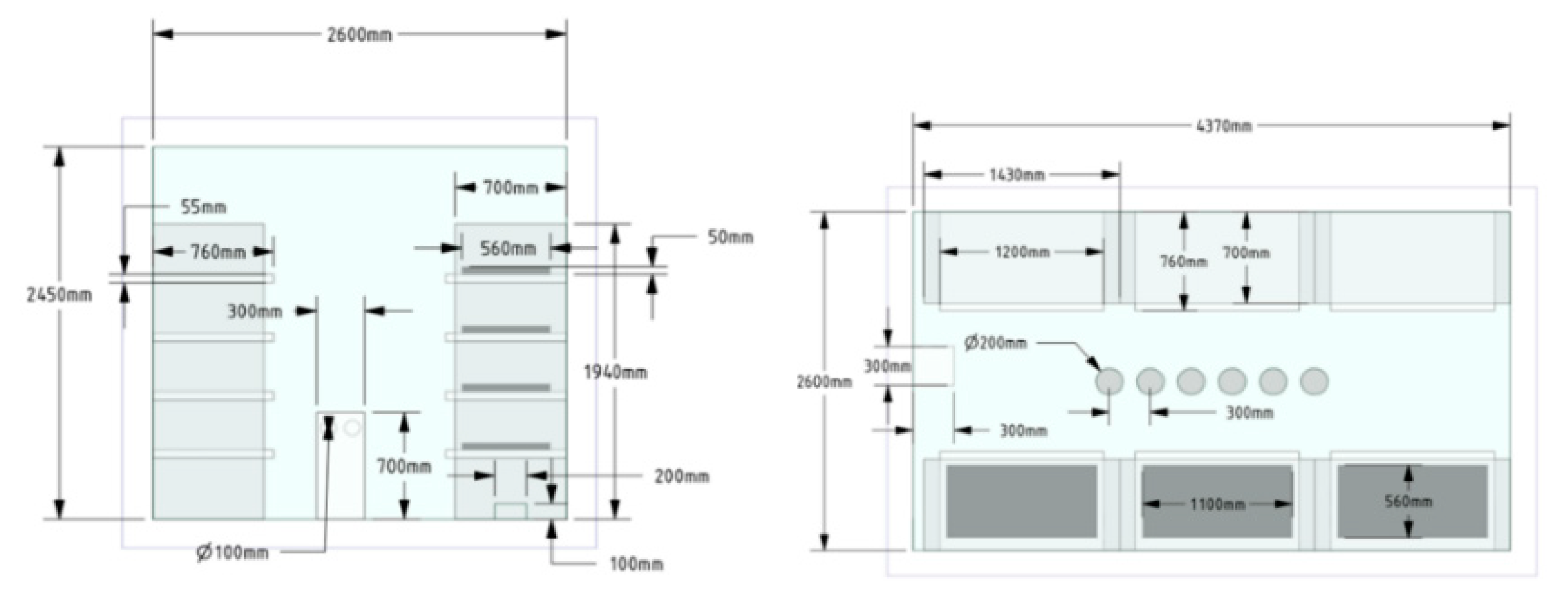
The experimental plant factory has been managed by the Korea Rural Development Administration and operates as an automatic air controlling system with closed ventilation structure. The dimensions of the seedling factory are 4.37 m (Length) × 2.6 m (Width) × 2.45 m (Height), as illustrated in
Figure 1. The cucumber and eggplant seedlings are cultivated for a period of 6 days inside the plant factory. The facility comprises 6 seedling stands with 4 shelves, arranged symmetrically.
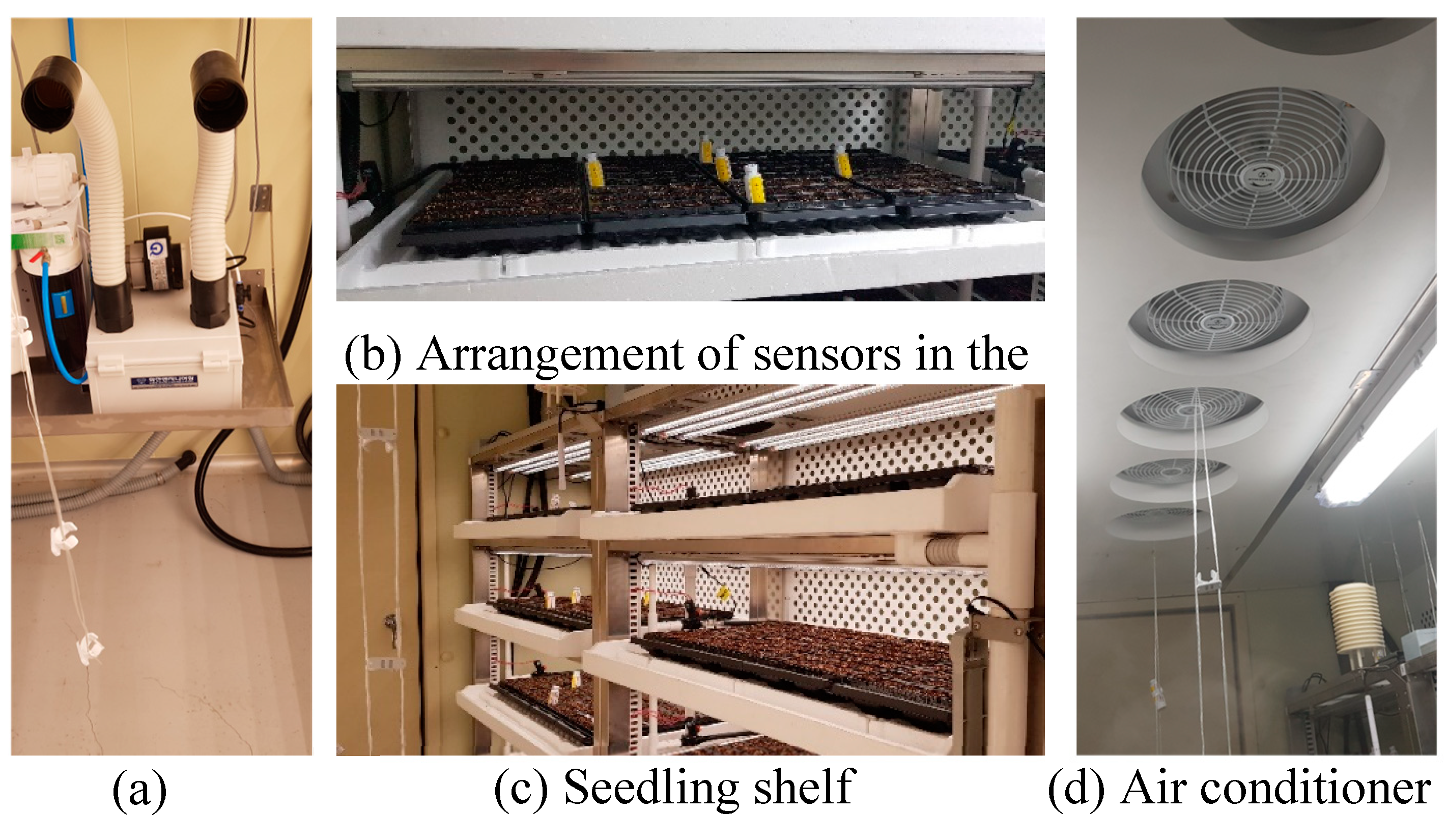
Figure 2 shows the installed air conditioning system on the ceiling and the humidifier on the floor, both used to regulate temperature and humidity during the seedling cultivation process. The seedling plant factory incorporates six outlets for the air conditioning system, each with a diameter of 0.2 m, installed in a row at the middle of the ceiling. The humidifier located in the wall opposite the seedling shelves, consists of two outlets with a diameter of 0.1 m and one inlet with a diameter of 0.2 m. To create a uniform exhaust flow, two side walls were covered with a porous panel, as shown in
Figure 2b and 2c. The installed porous panel has a total of 175 holes on the back of each shelf. Comparing this to the entire surface area, it accounts for 9.6% porosity. Instead of modeling each individual hole, we derived two coefficients and applied them to represent the porous surface efficiently. This approach simplifies the modeling process and reduces computational complexity while maintaining an accurate representation of the porous panel's behavior in the CFD simulations. The overall ventilation structure is designed in a recirculating manner. The air being exhausted through the porous panels on the sidewalls passes through heat exchangers installed in additional space before being reintroduced from the ceiling.
2.2. Computational fluid dynamics
CFD (Computational Fluid Dynamics) is a numerical analysis method that utilizes non-linear partial differential equations, including the Navier-Stokes equation, conservation of mass, Newton's second law, and the first law of thermodynamics, to simulate and predict fluid behavior[
35,
36]. In the field of agriculture, CFD has proven to be a powerful tool for analyzing the microclimate within agricultural facilities [
22,
35,
37,
38,
39]. For the simulations in this study, the commercial CFD software ANSYS Fluent (Ver. 2020 R1, ANSYS Inc., Canonsburg, PA) was utilized. The fluid flow in the seedling plant factory domain was assumed to be incompressible, steady-state, and three-dimensional turbulent flow. The governing equations for fluid flow and heat transfer are mathematical representations of the conservation laws of fluid dynamics, encompassing the conservation of mass, momentum, and energy. CFD applies Equations (1)-(3) to a discretized flow domain to calculate the systematic change in mass, momentum, and energy as the fluid passes through the boundary of each discrete domain [
35,
40,
41].
In CFD simulations, the selection of an appropriate turbulence model is crucial as it significantly influences the predicted results, particularly for turbulent flows. Due to the complexity of turbulent motion and its dependence on flow conditions and geometry, it is necessary to compare and validate different turbulence models. While the Navier-Stokes equations can be used for direct analysis of laminar flow, the fluid motion at Kolmogorov microscales associated with turbulent flow becomes computationally expensive. In greenhouse CFD simulations, the Reynolds Averaged Navier-Stokes (RANS) equations are typically used to account for the effects of turbulence through time averaging [
35] incorporating transfer equations for turbulent flow viscosity using variables such as turbulent kinetic energy (k) and turbulent flow dissipation (epsilon or omega). Among the RANS models, the k-epsilon model has been widely used in greenhouse studies [
24,
42,
43,
44]. While the k-omega model has been less commonly used in greenhouses, it offers advantages in boundary layers, which can be relevant in the case of plant factories where there are multiple objects compared to the available area. The turbulence models used for model validation in this research were Standard k-ε, Realizable k-ε, RNG (Re-Normalization Group) k-ε, and Shear-stress transport k-ω models. The transport equations for each turbulence model are as follows:
RNG(Re-Normalization Group) k-ε :
Shear-stress transport k-ω :
Where, C1ε and C2ε are constants with values of 1.42 and 1.68. C3ε is tanh(u1/u2). u1 and u2 are components of the flow velocities parallel and perpendicular to the gravitational vector. Pk is generation of turbulent kinetic energy due to the mean velocity gradient, kg m−1 s−2. Pb is generation of kinetic energy due to the buoyancy, kg m−1 s−2. k is turbulent kinetic energy, m−2 s−2. xi is velocity, m s−1. αk is generation of kinetic energy due to the mean velocity gradient, kg m−1 s−2. ε and ω are turbulence dissipation rate, m2 s−3. μ is viscosity, kg m−1 s−1. μt is turbulence viscosity, kg m−1 s−1. ρ is density, kg m−3. Sε is user defined source term. Cμ and σk are constants with values of 0.09 and 1.00. β is coefficient of thermal expansion. F1 is blending function.
In a humidifier, it is supplied inside in the form of water vapor. Therefore, an appropriate multiphase model should be used. MPM (Multi-Phase Mixture) can model phases (fluid or particulate) by solving the momentum, continuity, and energy equations for the mixture, the volume fraction equations for the secondary phases, and algebraic expressions for the relative velocities. The MPM model is expressed by continuity (Equation (8)) and momentum (Equation (9)) equations, which are simplified from the Eulerian Eulerian model by use of the relative velocity between each phase[
45].
Where, ρm is mixture density, kg m−3. υm is mass averaged velocity, m s−1. μm is viscosity of mixture, kg m−1 s−1.
In the experimental plant factory, the porous panels at the side walls were installed to make flow uniformity. A porous jump approach offers several advantages over directly implementing the porous panel, including reduced grid construction time, improved model calculation efficiency, and better convergence [
46]. The porous jump is a one-dimensional simplified calculation within the same cell area as the porous media. It is computed using Equation (10) as follows [
47].
Where, μ (Pa s) is the viscosity coefficient, ν (m s−1) is the initial flow velocity of the medium, α is the permeability coefficient, ρ (kg m−3) is the density of the medium, and C2 (m−1) is the pressure drop coefficient, Δm (m) is the thickness of the porous material, and p (Pa) is the pressure drop. The pressure drop, the initial flow velocity, the permeability coefficient, and pressure drop coefficient can be calculated through the trend curves.
2.3. Experimental procedure
2.3.1. Field monitoring in seedling plant factory
The seedling plant factory was equipped to artificially control temperature, humidity, and light. Ensuring uniform and stable temperature and humidity is crucial for the consistent production of seedlings within a short period in the seedling plant factory. To maintain a stable and uniform internal environment, we applied the exhaust system utilizing porous panels. To monitor this, 108 data loggers were evenly installed at various locations inside the seedling plant factory, and 24-hour field monitoring was conducted.
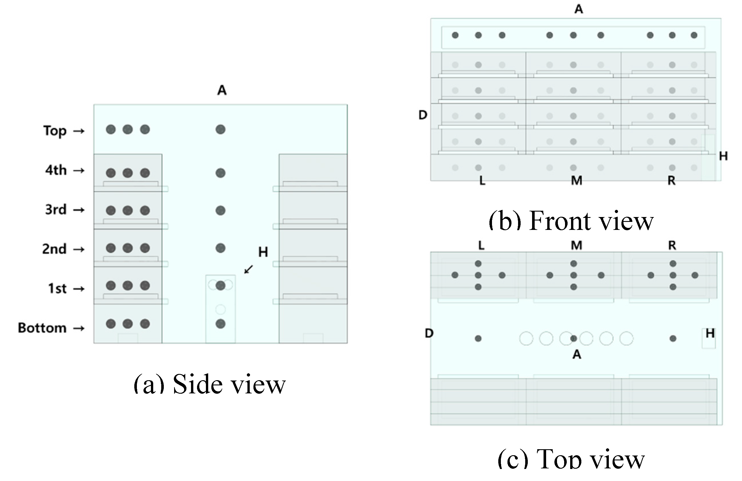
Figure 3 illustrates the layout of the seedling plant factory, where 3 seedling stands are divided into 6 floors including 4 cultivating shelves, and the workspace in front of the seedling table is also divided into 6 floors, resulting in a total of 36 monitoring zones. To measure the air velocity discharged from the humidifier and air conditioning system, a hot-wire anemometer (SFC900, Kimo electronic Pvt Ltd., France) was used. For the humidifier, the wind speed was measured at a point located 5 cm away from the outlet. As for the air conditioning system, the wind speed was measured with multiple points to make average wind speed. Internal temperature and humidity were monitored using a data logger (HOBO U23-001A, Onset Computer Corp., USA). Five temperature and humidity data loggers were uniformly installed at each monitoring zones. Monitoring was carried out during 24 hours, with the environmental conditions maintained consistently according to the photoperiod, which was operated with a light period of 16 hours, during which light is provided, and a dark period of 8 hours, during which light is not supplied. During the light period, LED lights provided a light intensity of 150 μmol m
−2 s
−1. The internal air conditions during the light period were set at 25°C of temperature and 70% of humidity, while during the dark period were set at 20°C of temperature and 85% of humidity. These conditions were maintained consistently throughout the monitoring period.
2.3.2. CFD model validation
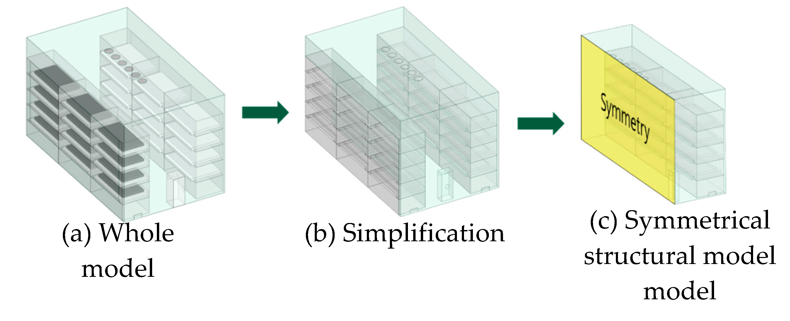
CFD model was developed to overcome the limitations of field experiments and enable precise aerodynamics analysis in the seedling plant factory. The model was designed to represent the structure and dimensions of the measured actual seedling plant factory. The seedling plant factory was simplified and designed by CFD model as shown in
Figure 4. Aerodynamically important structures were only considered to simplify the CFD model and improve computational efficiency. In ANSYS Fluent, the symmetry boundary condition can be utilized to analyze the plant factory. This boundary condition defines the physical shape, fluid flow, and thermal analysis in a reflective symmetric form centered on the boundary surface.
The domain of the seedling plant factory was divided into three sections: the working space, cultivation space, and the additional space for air circulation through the porous panel. Considering the significance of aerodynamics analysis, the grid for the CFD simulation was designed carefully as shown in
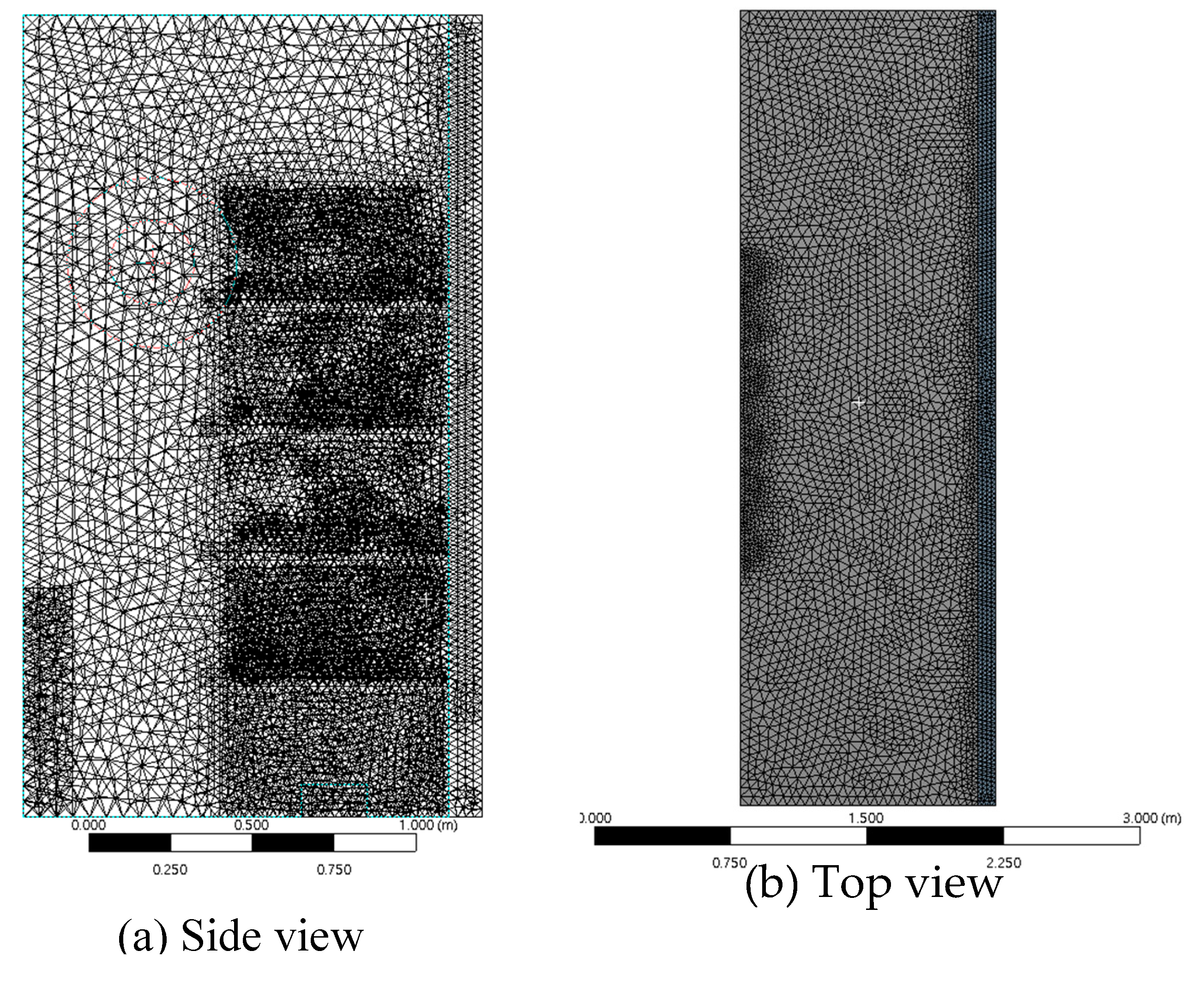
Figure 5. The grid resolution and structure were determined to ensure accurate representation of the flow characteristics within the seedling plant factory. The grid resolution throughout the seedling plant factory was set to a size of 5 cm considering under the volumetry sensing space. The model grid was designed based on the grid independence evaluation results used in previous studies[
48].
In the working space, where there are relatively fewer structures, the grid resolution was coarser compared to the growth space. The outlets of the air conditioning system and humidifier were designed to understand specific aerodynamic analysis with a finer grid resolution with a size smaller than 2.5 cm. The area near the porous panel is crucial for calculating complex flows involving diffusion and convection. The additional space for air circulation behind the porous panel is a narrow space with a 15 cm interval and is in contact with the growth space. The grid in the additional space for air circulation was configured with the same resolution as the growth space, taking into account the gradient of flow. The seedling plant factory model was composed of approximately 4.18 million tetrahedral grids. The quality of the grid was evaluated by calculating the skewness using Equation (11). The skewness of the grid was 0.21 on average, and had a skewness value in the appropriate range, with a maximum of 0.84 under suggestion by [
47].
The porous coefficients including permeability and pressure drop coefficients were determined through a preliminary CFD simulations, using a model illustrated in
Figure 6. The model dimensions correspond to the size of one seedling cultivation shelf with 1.43 m in length, 0.7 m in width, and 0.4 m in height. The porous panel consists of pores with a diameter of 20 mm, spaced at intervals of 25 mm. In the CFD model, the pressure loss was derived by CFD simulation according to various flow rates, which were applied to Equation (10) to calculate the permeability coefficient and pressure drop coefficient. This process allows for the determination of these coefficients based on the relationship between pressure drop and flow rate observed in the CFD simulations.
At the inlet, the conditioned air enters the seedling plant factory with a wind speed profile. In the outlet, the air is exhausted through a porous panel. Internal humidity is controlled using a humidifier, with moisture introduced into the interior at a mass fraction of 0.01035 and a flow rate of 1.44 m/s (
Table 1). Various materials are used in the construction of the plant factory. The air conditioning system, humidifier, and walls of the seedling board are made of ABS (Acrylonitrile Butadiene Styrene) plastic, while the seedling stand is made of iron. The inner walls of the seedling plant factory are composed of silicone polyester, which acts as an insulator.
The validation of the CFD model was performed by comparing the modeling results at the same locations with the field monitoring data. To evaluate the accuracy of the simulation model based on various turbulent models, several performance metrics were employed: root mean square error (RMSE), mean absolute error (MAE), and percent bias (PBIAS) calculated using the following equations (12), (13), and (14). These metrics provide quantitative measures of the model's predictive capability. The accuracy of the model is considered higher when the values of PBIAS, RMSE, and MAE are closer to 0. A PBIAS value that is positive indicates an underestimation of the simulation results, while a negative value suggests an overestimation.
Where ymodel,i means temperature or humidity data of the model at position i, and ymeasure,i means temperature and humidity data from field monitoring at position i. n means the number of data.
2.3.3. Aerodynamic analysis using CFD
The validated model was utilized to compare and analyze the temperature, humidity, and airflow pattern in 18 zones within the seedling stand at each location to assess the uniformity of these variables throughout the seedling plant factory. The CFD model was used to analyze the microclimate occurring within the seedling plant factor. Achieving uniform and stable production on-site relies on creating and maintaining environmental factors as uniformly as possible. Temperature and humidity distributions, which are difficult to observe and monitor comprehensively using experience and on-site sensors alone, were analyzed in all areas by using CFD simulation. The CFD model was computed on a computing system with an i7 CPU, 32GB RAM, and a 1600 Ti GPU. Transient modeling was employed, and the simulations were conducted for a total of 180 seconds, with a time step of 1 second, until the internal temperature distribution became stable. The computations took approximately 8 hours to complete. After 120 seconds, the internal average temperature showed minimal variation, indicating that the system reached a nearly steady state. Furthermore, airflow patterns were examined using CFD flow analysis to enhance the uniformity of environmental factors. The entire domain was divided into different regions, as shown in
Figure 7, to conduct qualitative aerodynamic analysis and analyze environmental distributions quantitatively. Based on these findings, recommendations for improvements were provided.
3. Results
3.1. Field monitoring installed porous panel
Field monitoring of temperature and humidity distribution in the
seedling plant factory were conducted with utilizing porous panels as the exhaust system to enhance internal uniformity.
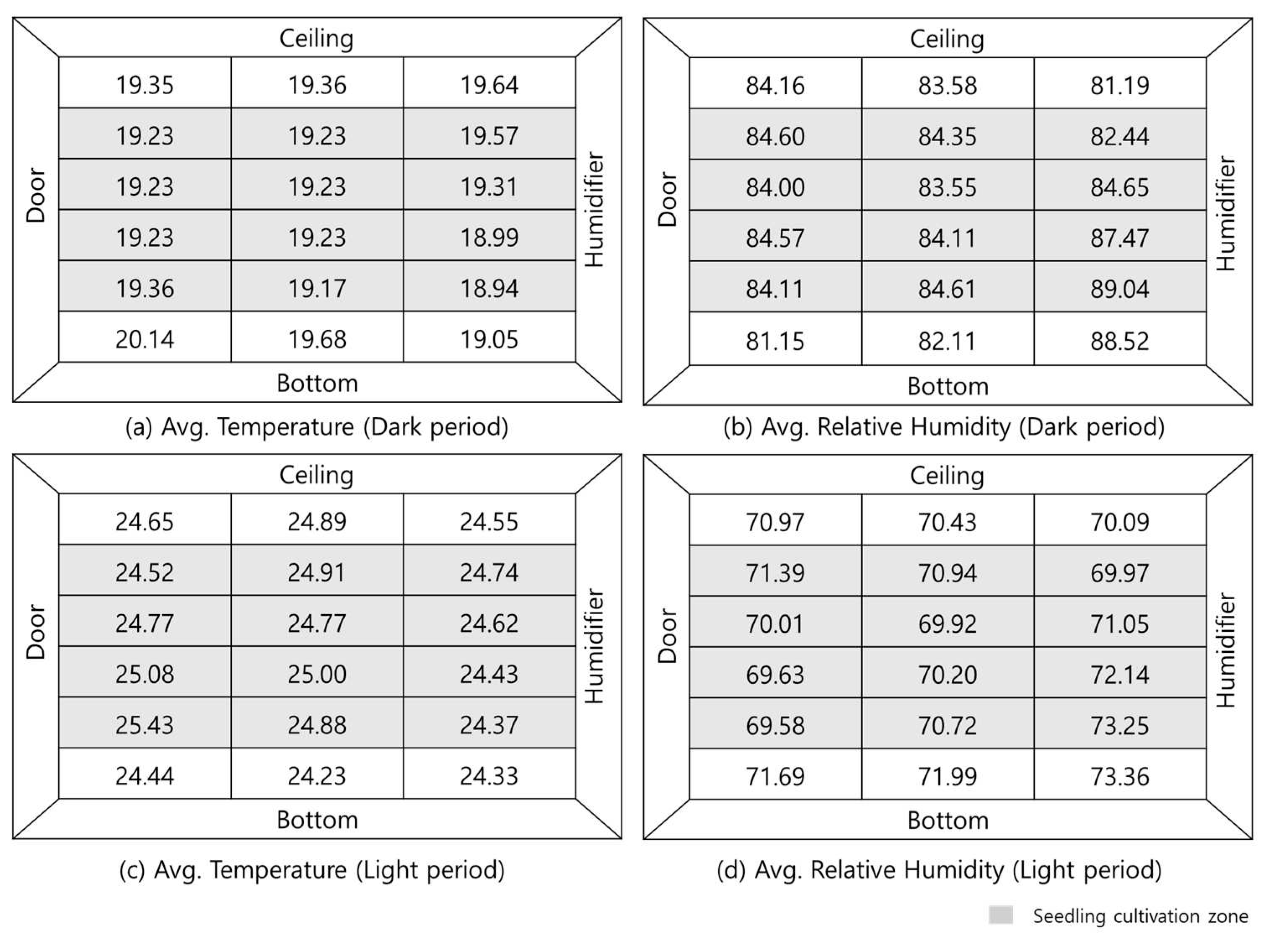
Figure 8 represents the average data divided into light and dark periods, collected from five data loggers for each cultivation shelf. The examination of the cultivation area revealed that during the light period, the temperature and humidity showed a deviation within 1% of the set values, with an average of 24.8°C and 70.7%, respectively, indicating precise operation. Even during dark period, the temperature and humidity remained stable at 19.2°C and 84.8%, respectively. The utilization of porous panels in the exhaust system resulted in an increased area for ventilation, leading to improved uniformity. As a result of the reduced airflow velocity and enhanced uniformity, the uniformity of internal environment could be enhanced.
The side closer to the humidifier showed an increase in humidity as moist air was introduced and evaporates, resulting in a relatively lower temperature. Conversely, the side farther from the humidifier tended to have a relatively higher temperature and lower humidity. To analyze the uniformity of temperature and humidity inside, we examined the difference between the maximum and minimum values of the average in each cultivation shelf. During the light period, temperature showed a difference of 0.42°C and humidity showed a difference of 6.6% across different cultivation areas. During the dark period, temperature showed a difference of 1.06°C and humidity showed a difference of 3.67%. Analyzing the absolute humidity, during the light period, there was a maximum difference of 1.14 g/kg-da, while during the dark period, there was a maximum difference of 0.47 g/kg-da.
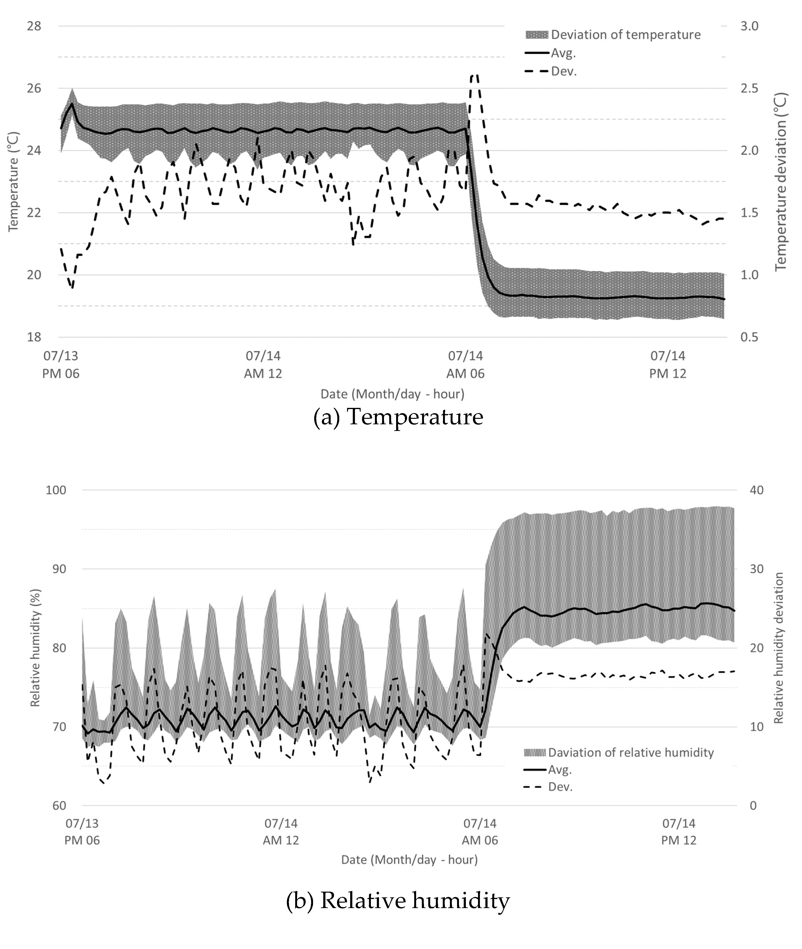
Figure 9 illustrates the changes in temperature and relative humidity over time within all the independent sensors. During the monitoring period, the regional temperature deviation had an average of 1.65°C and a maximum of 2.63 °C. As for humidity, the regional deviation had an average of 14.1% and a maximum of 23.8%. When transitioning from the light period to the dark period, there was a sudden and significant change of −6°C in temperature and +15% in relative humidity within 30 minutes. In the light period, the on/off cycles of the humidifier and the air conditioner were operated periodically, resulting in significant fluctuations. Particularly, due to the operating conditions of the humidifier and the high flow rate of the air conditioner, there were significant variations in relative humidity (
Figure 9). The analysis based on the average values indicates a relatively high level of uniformity. However, upon detailed examination, it becomes evident that there is a need for improvement in uniformity depending on the location. Since the field monitoring alone has limitations, a detailed CFD model is necessary to conduct precise aerodynamic analysis. By utilizing CFD, we can gain a deeper understanding of the flow patterns and identify areas that require further optimization to achieve better uniformity in the internal environment.
3.2. CFD model validation
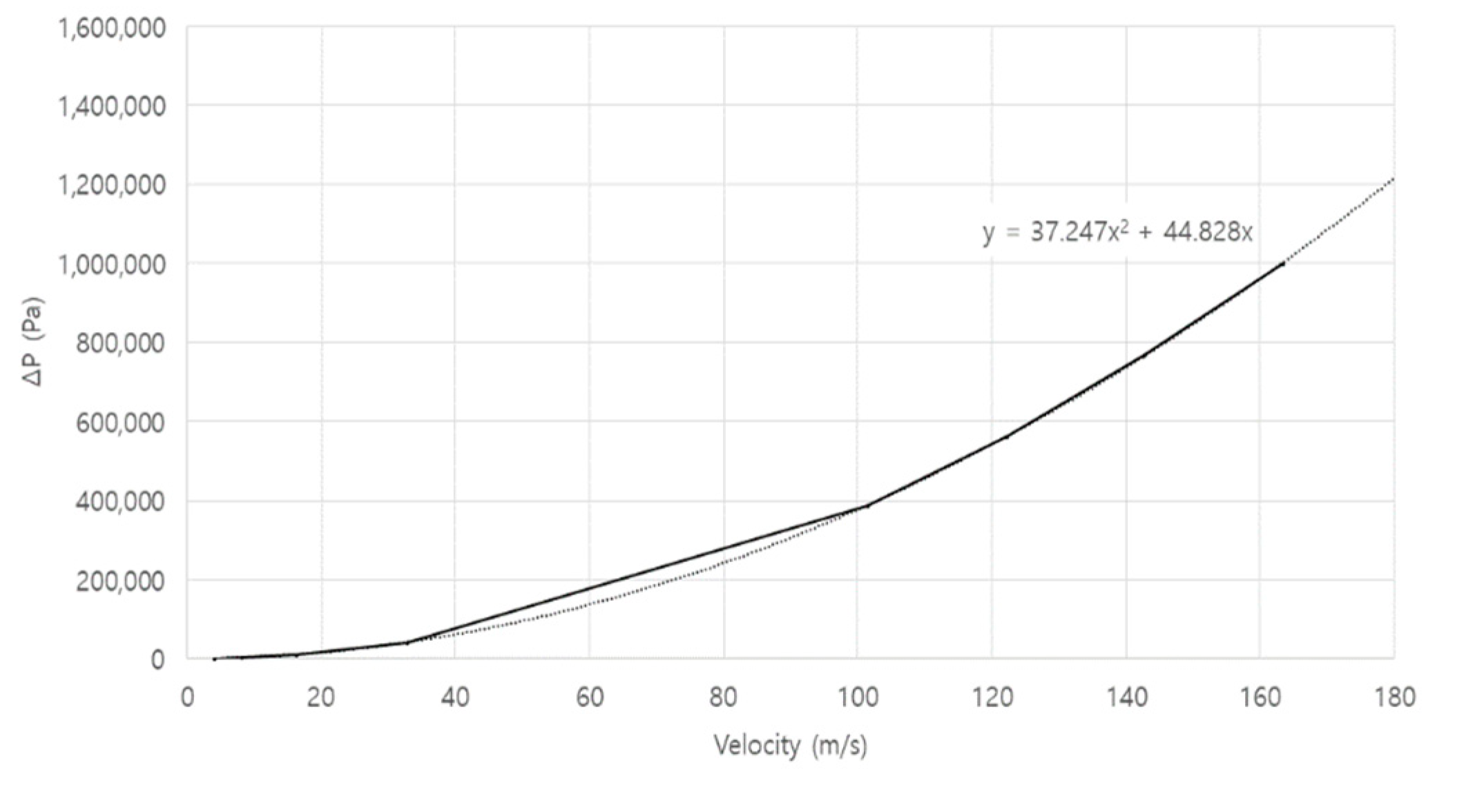
The obtained data from multiple measurement points in the field experiment were used to validate the CFD model. The CFD model was designed to reflect the same structural configuration and operating conditions as the actual seedling plant factory where the experiments were conducted. Relatively stable air environmental data from a specific period were used to obtain basic data for validation. For effective validation of the CFD model, simulations were performed based on the average environmental conditions during the dark period, which exhibited spatial variations despite temporal stability. Pre-simulations were conducted to obtain the coefficient settings for the porous panel following actual design. Pressure loss curves, as shown in
Figure 10, were derived by gradually increasing the flow velocity from 2 m/s to 150 m/s. Based on the trend curve and Equation (10), the permeability coefficient α was determined as 1.20 e
−9 and the pressure drop coefficient C
2 as 19,204, which were then applied to the CFD simulation.
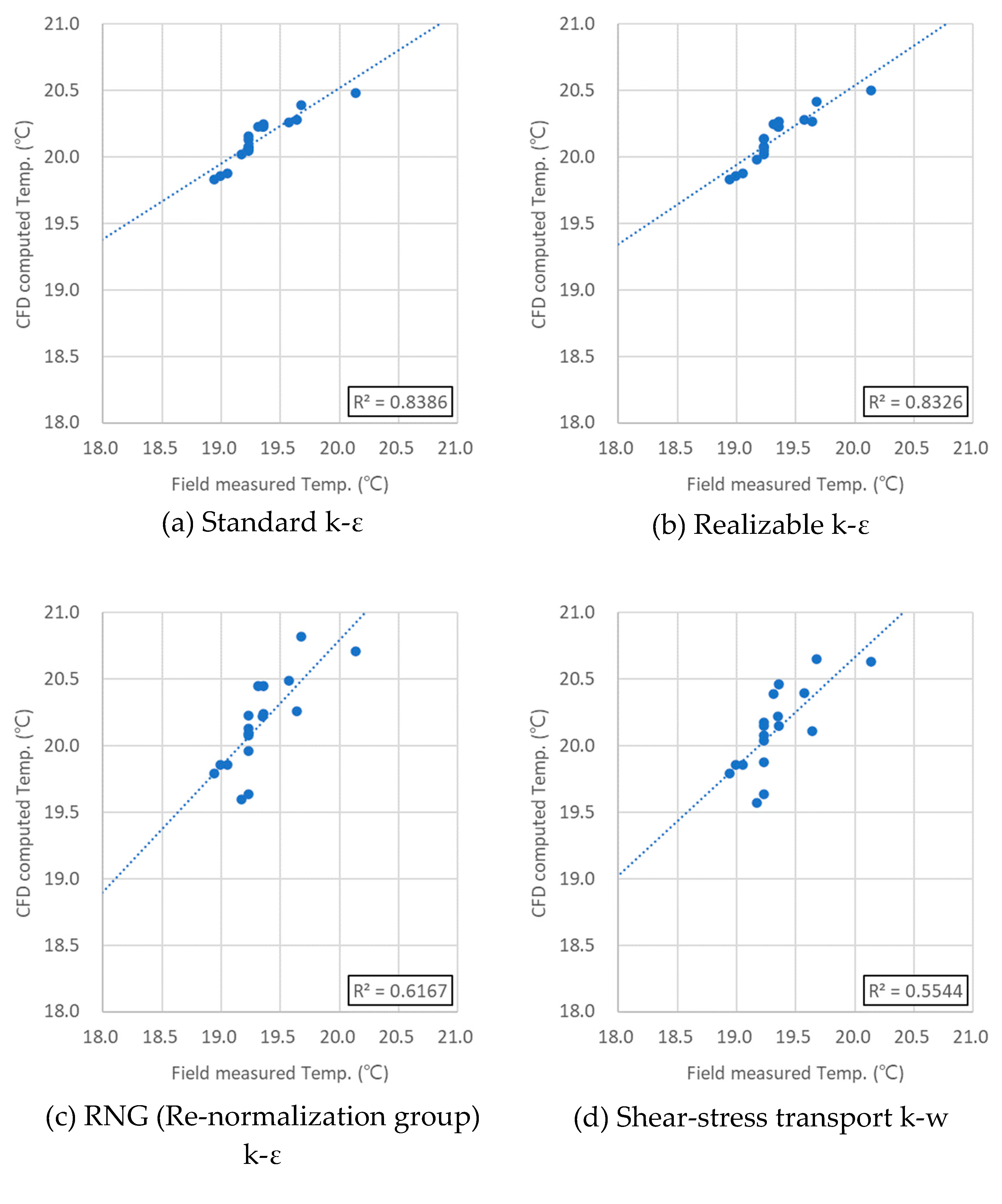
CFD model was validated by using four different turbulence models, and the results were compared with the monitoring data obtained from the same locations in the field experiment. As shown in
Figure 11, the R
2 values were higher for the Realizable k-ε model and the Standard k-ε model compared to the RNG (Re-Normalization Group) k-ε model and the Shear-stress transport k-ω model. The model errors were found to be 4.0% for the Realizable model, 4.0% for the Standard model, 4.2% for the Shear-stress model, and 4.0% for the RNG model, indicating a very good simulation of the field conditions. Analysis of RMSE, MAE, and PBIAS for model validation did not show significant differences among the models as shown in
Table 2. However, for humidity, the Realizable k-ε model exhibited better accuracy, leading to its selection as the final turbulence model. The analysis of the results, using the monitored data as reference, showed that the CFD model exhibited very accurate simulations with errors of 5.2 ± 1.1% for temperature and 1.7 ± 1.5% for humidity. This demonstrates that the CFD model is highly reliable in predicting and simulating the temperature and humidity distributions at the same time and location as the monitoring data. With such precision, the CFD model can serve as a valuable tool for further analysis and optimization of the internal environment to achieve desired uniformity levels.
3.3. Aerodynamic analysis using CFD
The validated CFD model was utilized to interpret the airflow, temperature, and humidity distributions within the challenging-to-analyze internal aerodynamics of the seedling plant factory. The CFD computed results were qualitatively analyzed by dividing them into longitudinal and cross-sectional directions to understand the flow patterns and distribution of temperature and humidity. Additionally, quantitative analysis was performed using the CFD modeling results from the same locations as the monitoring points in the field experiments.
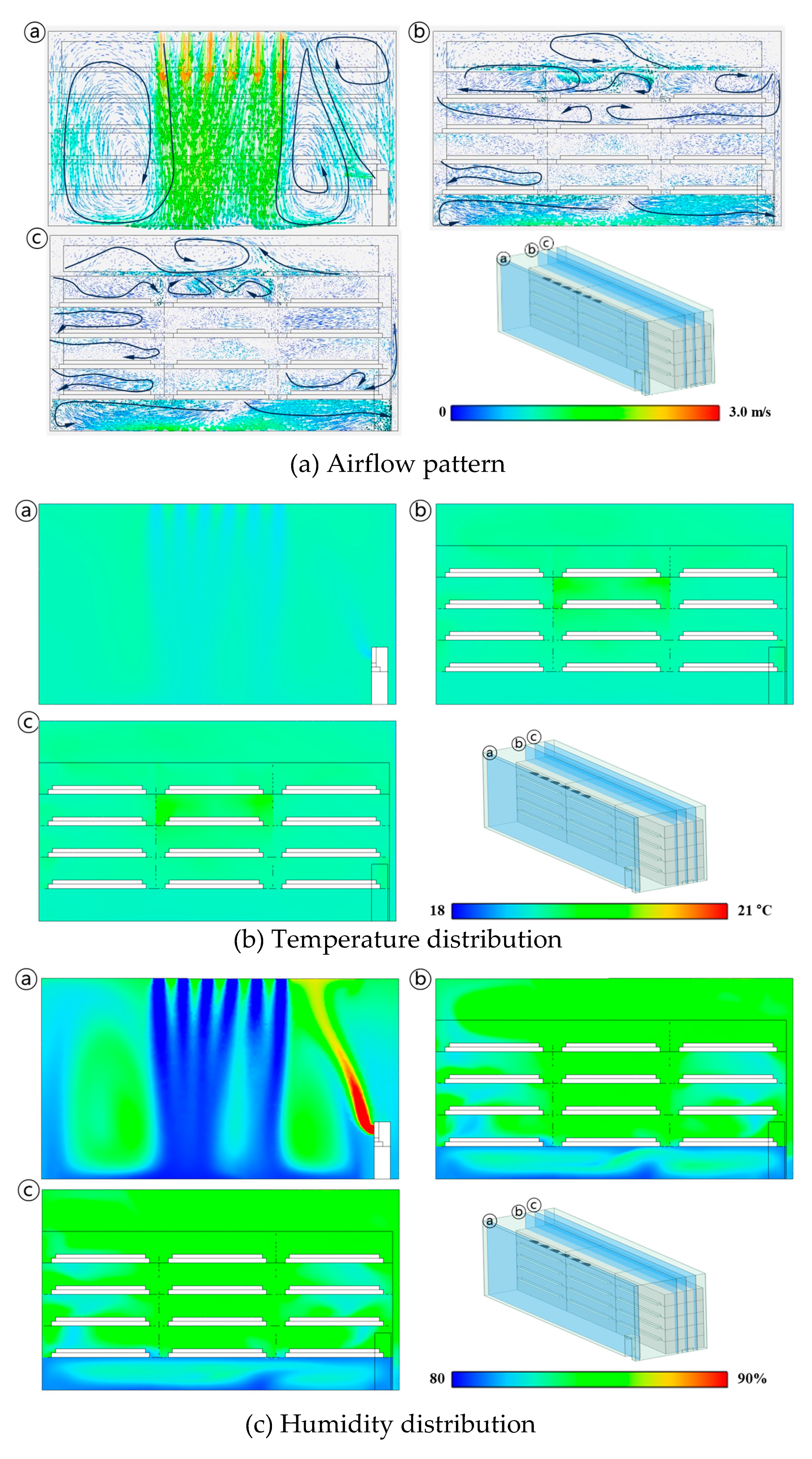
Figure 12 illustrates the flow field, temperature distribution, and humidity distribution in the longitudinal direction. The descending flow strongly introduced from the air conditioner enters to the corridor and spreads in both longitudinal directions (
Figure 12a). This results in an updraft near the door and the humidifier due to the formation of vortices. The air released from the humidifier extends upward due to this updraft. As a result, the humidity increases in the cultivation shelves on the 1st, 2nd, 3rd, and 4th shelves near the humidifier, compared to the shelves on the 1st shelf in the direction where the humidified air is emitted. Additionally, due to evaporation, the temperature tends to decrease in these areas.
Figure 12b shows the temperature distribution, which showed a very uniform pattern. However, a temperature increase can be observed on the 2nd and 3rd shelves within the region where the air was stagnated.
Figure 12c represents the air humidity distribution. The relatively low humidity air coming down through the air conditioner is observed to move along the floor. Fast-moving air coming down from the ceiling reaches the floor before mixing with the internal air. The stagnant air on the floor gradually diffuses throughout the interior, following the circulating air flow. The air released from the humidifier moves upward due to the updraft and then spreads from the roof direction. Compared to the overall air velocity, the air descending from the ceiling flows more strongly, and the flow is restricted near the floor due to shelf structures. While the temperature of the incoming air does not greatly differ from the internal air, the effects of the flow field on humidity are clearly noticeable.
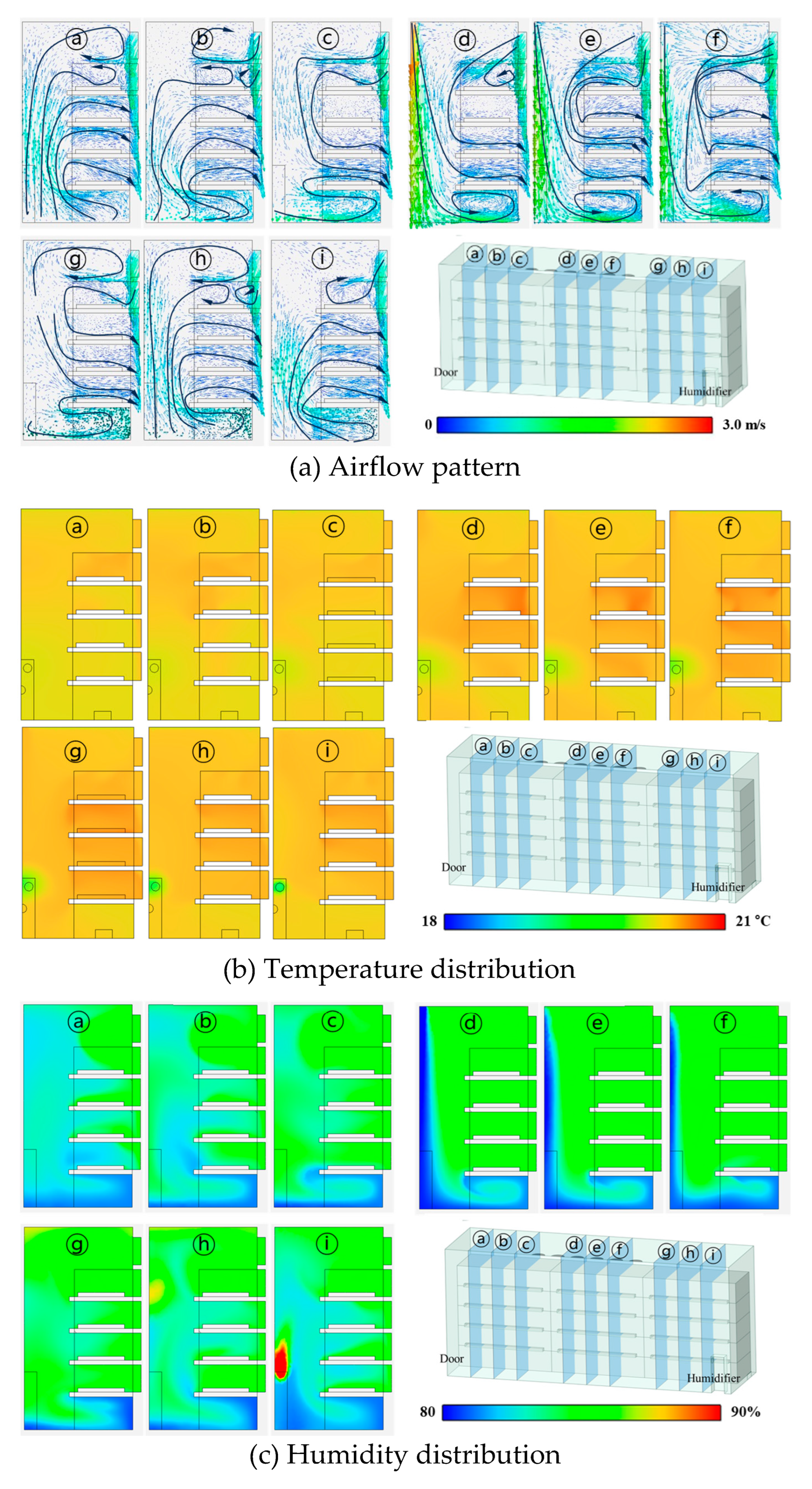
Figure 13 represents the cross-sectional view of the flow field, temperature, and humidity distribution. As shown in
Figure 13a, in the region with the central cultivation shelf, a strong downward airflow is formed in the corridor due to the intense inflow from the air conditioner. As a result, on the 4th shelf, the amount of air introduced from the air conditioner is significantly reduced, causing reverse flow from the porous panel and a concentration of conditioned air in the lower region. In sections ⓐⓑⓗⓘ, upward flows are observed at both ends where the door and humidifier are located, and a stagnant region with very low airflow is formed on the 3rd shelf. In
Figure 13b, for the cultivation shelves behind the strong descending flow from the air conditioner, it is observed that there is a stagnant region where cool air is not directly introduced, resulting in relatively higher temperatures. In
Figure 13c, the air introduced from the humidifier moves upward following the circulating airflow inside and then diffuses from the ceiling.
The analysis of internal airflow revealed that on the first and second shelves near the bottom floor, there is a proper level of air inflow due to strong currents coming from the ceiling. The air enters indirectly and circulates through the floor, creating a uniform flow pattern through the porous panel exhaust. However, on the third shelf, there is a significant area of air stagnation, and on the fourth shelf, there is reverse airflow from the porous panel. Identifying these airflow patterns provides valuable insights into the challenges faced in improving the environmental conditions for the seedling plant factor. These aspects are difficult to observe directly on-site and will require careful consideration for future improvements.
Table 3-5 represent the average velocity, temperature, and relative humidity for each cultivation shelf computed by CFD. The velocity is generally higher near the floor, and among the cultivation shelves, the 1st and 2nd shelves have higher velocities, which can be attributed to the influence of the air conditioner. The 3rd shelf is influenced by the internal airflow circulation, resulting in lower velocities in the regions near the door and humidifier on the 2nd and 3rd shelves. On the 4th shelf, there is no direct influence from the air conditioner, but reverse flow occurs from the porous panel. When analyzing the cultivation shelves individually, the velocity showed a difference of up to 0.38 m/s and a minimum difference of 0.10 m/s, while the average temperature exhibited a maximum difference of 0.50 degrees. The relative humidity showed a maximum difference of 1.47% in all cultivation shelves, indicating a very uniform distribution. This appears to be very uniform when averaged over each shelf. However, analyzing the CFD results at the same location as the sensor measurements, the airflow showed variations of 0.29 ± 0.16 m s
−1, with a maximum deviation of 0.56 m s
−1. The temperature and humidity showed results of 20.14 ± 0.19 °C (maximum deviation of 1.00 °C) and 84.4 ± 0.9% (maximum deviation of 3.3%), respectively. Compared to the monitoring results, CFD-computed results showed relatively uniform outcomes, and through the flow field, we were able to identify stagnant sections and areas with reverse flow that influence the uniformity of temperature and humidity.
Table 3.
Air velocity distribution as a result of CFD modeling.
Table 3.
Air velocity distribution as a result of CFD modeling.
| Location (Average) |
Door (0.25) |
Cooler (0.27) |
Humidifier (0.34) |
| Perforated plate |
|---|
| Ceiling (0.40) |
0.51 |
0.49 |
0.42 |
| 4th (0.25) |
0.15±0.03 |
0.29±0.16 |
0.12±0.04 |
| 3rd (0.14) |
0.10±0.02 |
0.20±0.05 |
0.17±0.01 |
| 2nd (0.19) |
0.13±0.02 |
0.38±0.04 |
0.13±0.04 |
| 1st (0.39) |
0.25±0.06 |
0.38±0.04 |
0.23±0.07 |
| Bottom (0.33) |
0.36 |
0.28 |
0.55 |
| Corridor |
Table 4.
Air temperature distribution as a result of CFD modeling.
Table 4.
Air temperature distribution as a result of CFD modeling.
| Location (Average) |
Door (20.10) |
Cooler (20.07) |
Humidifier (20.30) |
| Perforated plate |
|---|
| Ceiling (20.09) |
20.2 |
20.2 |
20.2 |
| 4th (20.17) |
20.3±0.05 |
20.3±0.05 |
20.3±0.03 |
| 3rd (20.26) |
20.1±0.03 |
20.6±0.13 |
20.0±0.02 |
| 2nd (20.24) |
20.1±0.02 |
20.4±0.03 |
20.0±0.01 |
| 1st (20.12) |
20.1±0.03 |
20.2±0.03 |
20.0±0.04 |
| Bottom (19.86) |
19.8 |
19.9 |
19.9 |
| Corridor |
Table 5.
Air relative humidity distribution as a result of CFD modeling.
Table 5.
Air relative humidity distribution as a result of CFD modeling.
| Location (Average) |
Door (83.9) |
Cooler (84.1) |
Humidifier (84.9) |
| Perforated plate |
|---|
| Ceiling (84.0) |
84.9 |
85.3 |
85.0 |
| 4th (84.8) |
84.0±0.36 |
85.0±0.01 |
85.0±0.03 |
| 3rd (84.7) |
84.6±0.14 |
85.0±0.01 |
83.6±0.40 |
| 2nd (84.6) |
83.7±0.41 |
85.0±0.01 |
84.2±0.40 |
| 1st (84.3) |
83.5±0.59 |
84.8±0.07 |
84.4±0.42 |
| Bottom (82.8) |
82.8 |
83.0 |
82.6 |
| Corridor |
4. Discussion
To improve the environmental uniformity in the seedling plant factory, we implemented the porous panel exhaust system. The field monitoring results showed that the average temperature and humidity had good uniformity, allowing for precise operation. However, at specific locations, temperature deviations of up to 2.63°C and humidity deviations of 23.8% were observed. To investigate the causes of these deviations, we utilized CFD model to perform a microclimate analysis within the seedling plant factory, employing the porous panel exhaust system. The non-uniformity in the air environment at the site arises due to the closed ventilation structure and its configuration. Air from the air conditioner flows downward in a positive pressure, ensuring proper exhaust in the 1st and 2nd shelves. However, in the 4th shelf, where relative negative pressure exists, reverse airflow occurs. Similarly, the 3rd shelf experiences stagnation zones. As the experimental seedling plant factory was relatively small, it is expected that scalability could lead to even poorer uniformity. Therefore, addressing and optimizing these issues will be essential for ensuring consistent and improved air quality as the scale of the facility expands.
Based on aerodynamic analysis results, to improve the uniformity of the seedling plant factory, it is necessary to propose methods to make the velocity and temperature more uniform, particularly by addressing improvements in the airflow patterns. To suggest structural improvements based on the CFD computed results, it is important to utilize the existing structure as much as possible and consider cost-effective approaches to enhance efficiency. Due to the concentration of the air conditioner in the central area, which leads to decreased uniformity between the door side and humidifier side, it is necessary to widen the inflow area of the air to improve uniformity. Additionally, reducing the incoming velocity to decrease the temperature and humidity differences between cultivation shelves is crucial for achieving higher uniformity. Installing air induction panels to enable effective airflow into each cultivation shelf is also necessary.
5. Conclusions
To increase productivity in the seedling plant factory, ensuring uniform growth of the seedlings is crucial. This can be achieved by maintaining consistent environmental conditions across all cultivation shelves. Field experiments were conducted by installing data loggers in the seedling plant factory, which revealed the regional temperature deviation had an average of 1.65°C and a maximum of 2.63 °C. As for humidity, the regional deviation had an average of 14.1% and a maximum of 23.8%. Considering the scale of the seedling plant factory, these differences indicate a need for improvement. The CFD model was developed and validated to examine the micro-climate in the seedling plant factory. By utilizing the CFD model, we evaluated the uniformity of temperature, humidity, and airflow within the seedling plant factory. This analysis allowed us to identify areas of stagnation and reverse airflow, which were challenging to observe directly on-site. The CFD simulations provided valuable insights into the air distribution and allowed us to pinpoint potential areas for improvement to enhance the overall uniformity of the environmental conditions within the facility. In future research, it is important to explore detailed improvement approaches such as design modifications of the porous panel, installation of airflow control panels, and the necessity of circulation fans. These measures can help address the fluid dynamics issues identified in this study and further enhance the productivity and uniformity of the seedling plant factory.
Acknowledgments
This work was carried out with the support of "Cooperative Research Program for Agriculture Science and Technology Development (Project No. RS-2022-RD010412)" Rural Development Administration, Korea.
References
- Mariani, L.; Ferrante, A. Agronomic management for enhancing plant tolerance to abiotic stresses—drought, salinity, hypoxia, and lodging. Horticulturae 2017, 3, 52. [Google Scholar] [CrossRef]
- Shibuya, T.; Kozai, T. Effects of air current speed on net photosynthetic and evapotranspiration rates of a tomato plug sheet under artificial light. Environment Control in Biology 1998, 36, 131–136. [Google Scholar] [CrossRef]
- Savvas, D.; Passam, H. Hydroponic production of vegetables and ornamentals; Embryo publications Athens: 2002.
- Kitaya, Y.; Tsuruyama, J.; Shibuya, T.; Yoshida, M.; Kiyota, M. Effects of air current speed on gas exchange in plant leaves and plant canopies. Advances in Space Research 2003, 31, 177–182. [Google Scholar] [CrossRef] [PubMed]
- Ritchie, J.; Nesmith, D. Temperatures and crop development. Modeling plant and soil systems. Agronomy Monograph No. 31; ASA-CSSA-SSSA, Madison, WI53711, USA: 1991.
- Sase, S. Air movement and climate uniformity in ventilated greenhouses. International Symposium on Greenhouse Cooling 719 2006, 313–324. [Google Scholar] [CrossRef]
- Chen, C. Humidity in plant tissue culture vessels. Biosystems Engineering 2004, 88, 231–241. [Google Scholar] [CrossRef]
- Körner, C. Significance of temperature in plant life. Plant Growth and Climate Change 2006, 48–69. [Google Scholar] [CrossRef]
- Deng, L.; Wang, K.; Li, J.; Zhao, G.; Shangguan, Z. Effect of soil moisture and atmospheric humidity on both plant productivity and diversity of native grasslands across the Loess Plateau, China. Ecological Engineering 2016, 94, 525–531. [Google Scholar] [CrossRef]
- Lakhiar, I.A.; Gao, J.; Syed, T.N.; Chandio, F.A.; Buttar, N.A. Modern plant cultivation technologies in agriculture under controlled environment: A review on aeroponics. Journal of Plant Interactions 2018, 13, 338–352. [Google Scholar] [CrossRef]
- Knowledge industry information institute(KNIN). Analysis of the latest technological trends in the agricultural and livestock industry/agricultural machinery and R&D strategies in the high value-added food industry Korea; Knowledge industry information institute(KNIN): Seoul, 2020. [Google Scholar]
- Zhou, Y.; Wang, S.; Hu, H.; Shen, Y.; Zhu, Y.; Liu, X.; Wei, J.; Yu, X.; Liu, S.; Ma, H. GmCDPKSK5 Interacting with GmFAD2-1B Participates in Regulation of Seed Development in Soybean Under High Temperature and Humidity Stress. Plant Molecular Biology Reporter 2022, 1–16. [Google Scholar] [CrossRef]
- Zhang, Y.; Kacira, M. Analysis of environmental uniformity in a plant factory using computational fluid dynamics (CFD) analysis. International Symposium on New Technologies for Environment Control, Energy-Saving and Crop Production in Greenhouse and Plant 1227, 2017; 607–614. [Google Scholar] [CrossRef]
- Kozai, T. Current status of plant factories with artificial lighting (PFALs) and smart PFALs. Smart Plant Factory: The Next Generation Indoor Vertical Farms, 2018; 3–13. [Google Scholar] [CrossRef]
- Hadavi, E.; Ghazijahani, N. Closed and semi-closed systems in agriculture. Sustainable Agriculture Reviews 33: Climate Impact on Agriculture, 2018; 295–310. [Google Scholar] [CrossRef]
- Zhang, Y.; Kacira, M. Air Distribution and Its Uniformity. Smart Plant Factory: The Next Generation Indoor Vertical Farms, 2018; 153–166. [Google Scholar] [CrossRef]
- Den Besten, J. Vertical farming development; the Dutch approach; Elsevier: 2019; pp. 307–317.
- Zhang, Y.; Kacira, M.; An, L. A CFD study on improving air flow uniformity in indoor plant factory system. Biosystems Engineering 2016, 147, 193–205. [Google Scholar] [CrossRef]
- Yu, H.; Yu, H.; Zhang, B.; Chen, M.; Liu, Y.; Sui, Y. Quantitative Perturbation Analysis of Plant Factory LED Heat Dissipation on Crop Microclimate. Horticulturae 2023, 9, 660. [Google Scholar] [CrossRef]
- Haibo, Y.; Lei, Z.; Haiye, Y.; Yucheng, L.; Chunhui, L.; Yuanyuan, S. Sustainable Development Optimization of a Plant Factory for Reducing Tip Burn Disease. Sustainability 2023, 15, 5607. [Google Scholar] [CrossRef]
- Fatnassi, H.; Pizzol, J.; Senoussi, R.; Biondi, A.; Desneux, N.; Poncet, C.; Boulard, T. Within-crop air temperature and humidity outcomes on spatio-temporal distribution of the key rose pest Frankliniella occidentalis. PloS one 2015, 10, e0126655. [Google Scholar] [CrossRef] [PubMed]
- Fang, H.; Li, K.; Wu, G.; Cheng, R.; Zhang, Y.; Yang, Q. A CFD analysis on improving lettuce canopy airflow distribution in a plant factory considering the crop resistance and LEDs heat dissipation. Biosystems Engineering 2020, 200, 1–12. [Google Scholar] [CrossRef]
- Noh, A.M.; Noor, H.M.; Ahmad, F. CFD Simulation of the Airflow Distribution Inside Cube-Grow. CFD Letters 2021, 13, 81–89. [Google Scholar] [CrossRef]
- Boulard, T.; Kittas, C.; Roy, J.; Wang, S. SE—Structures and environment: Convective and ventilation transfers in greenhouses, part 2: Determination of the distributed greenhouse climate. Biosystems Engineering 2002, 83, 129–147. [Google Scholar] [CrossRef]
- De Baerdemaeker, J.; Delele, M.A.; Verboven, P.; Nicolaï, B.M. Multiscale modelling of postharvest storage of fruit and vegetables in a plant factory context. IFAC Proceedings Volumes 2011, 44, 616–620. [Google Scholar] [CrossRef]
- Baek, M.-S.; Kim, K.-M.; Kwon, S.-Y.; Kong, H.; Lim, J.-H. CFD Based Internal Fan Control Simulation for Improvement of Cultivation Environment in Plant Factory. Adv. Sci. Technol. Lett 2015, 120, 550–553. [Google Scholar] [CrossRef]
- Niam, A.; Muharam, T.; Widodo, S.; Solahudin, M.; Sucahyo, L. CFD simulation approach in determining air conditioners position in the mini plant factory for shallot seed production. In Proceedings of the AIP Conference Proceedings; 2019. [Google Scholar]
- Fan, R.; Liu, H.; Zhou, S.; He, Z.; Zhang, X.; Liu, K.; Wang, J.; Yang, Q.; Zheng, Y.; Lu, W. CFD simulation of the airflow uniformity in the plant factory. IOP Conference Series: Earth and Environmental Science 2020, 560, 12–74. [Google Scholar] [CrossRef]
- Zhou, S.; Liu, H.; Fan, R.; He, Z.; Zhang, Y.; Chen, Y.; Sun, X.; Zhou, X.; Yang, Q.; Zheng, Y. Temperature field simulation using CFD in the plant factory. IOP Conference Series: Earth and Environmental Science 2020, 560, 12–36. [Google Scholar] [CrossRef]
- Chu, C.-R.; Lan, T.-W.; Tasi, R.-K.; Wu, T.-R.; Yang, C.-K. Wind-driven natural ventilation of greenhouses with vegetation. Biosystems engineering 2017, 164, 221–234. [Google Scholar] [CrossRef]
- Seo, I.-H.; Lee, H.J.; Wi, S.H.; Lee, S.-W.; Kim, S.K. Validation of an air temperature gradient using computational fluid dynamics in a semi-open type greenhouse and determination of kimchi cabbage physiological responses to temperature differences. Horticulture, Environment, and Biotechnology 2021, 62, 737–750. [Google Scholar] [CrossRef]
- Miguel, A.F.; Silva, A. Porous materials to control climate behaviour of enclosures: an application to the study of screened greenhouses. Energy and Buildings 2000, 31, 195–209. [Google Scholar] [CrossRef]
- Teitel, M.; Dvorkin, D.; Haim, Y.; Tanny, J.; Seginer, I. Comparison of measured and simulated flow through screens: Effects of screen inclination and porosity. Biosystems Engineering 2009, 104, 404–416. [Google Scholar] [CrossRef]
- Santolini, E.; Pulvirenti, B.; Benni, S.; Barbaresi, L.; Torreggiani, D.; Tassinari, P. Numerical study of wind-driven natural ventilation in a greenhouse with screens. Computers and Electronics in Agriculture 2018, 149, 41–53. [Google Scholar] [CrossRef]
- Norton, T.; Sun, D.-W.; Grant, J.; Fallon, R.; Dodd, V. Applications of computational fluid dynamics (CFD) in the modelling and design of ventilation systems in the agricultural industry: A review. Bioresource Technology 2007, 98, 2386–2414. [Google Scholar] [CrossRef] [PubMed]
- Kwon, K.-s.; Lee, I.-b.; Ha, T. Identification of key factors for dust generation in a nursery pig house and evaluation of dust reduction efficiency using a CFD technique. Biosystems Engineering 2016, 151, 28–52. [Google Scholar] [CrossRef]
- Piscia, D.; Montero, J.I.; Baeza, E.; Bailey, B.J. A CFD greenhouse night-time condensation model. Biosystems Engineering 2012, 111, 141–154. [Google Scholar] [CrossRef]
- Peiro, E.; Pannico, A.; Colleoni, S.G.; Bucchieri, L.; Rouphael, Y.; De Pascale, S.; Paradiso, R.; Gòdia, F. Air distribution in a fully-closed higher plant growth chamber impacts crop performance of hydroponically-grown lettuce. Frontiers in Plant Science 2020, 11, 537. [Google Scholar] [CrossRef]
- Zhou, S.; Zhang, X.; He, Z.; Liu, H.; Liu, K.; Chen, Y.; Peng, F.; Yang, Q.; Zheng, Y.; Lu, W. Experimental validation of CFD model with the air velocity and temperature in the plant factory. IOP Conference Series: Earth and Environmental Science 2020, 560, 12–89. [Google Scholar] [CrossRef]
- Versteeg, H.K.; Malalasekera, W. An introduction to computational fluid dynamics: the finite volume method; Pearson education: 2007.
- Seo, I.-H.; Lee, I.-B.; Moon, O.-K.; Kim, H.-T.; Hwang, H.-S.; Hong, S.-W.; Bitog, J.; Yoo, J.-I.; Kwon, K.-S.; Kim, Y.-H. Improvement of the ventilation system of a naturally ventilated broiler house in the cold season using computational simulations. Biosystems Engineering 2009, 104, 106–117. [Google Scholar] [CrossRef]
- Bournet, P.E.; Khaoua, S.O.; Boulard, T. Numerical prediction of the effect of vent arrangements on the ventilation and energy transfer in a multi-span glasshouse using a bi-band radiation model. Biosystems Engineering 2007, 98, 224–234. [Google Scholar] [CrossRef]
- Kim, K.; Yoon, J.-Y.; Kwon, H.-J.; Han, J.-H.; Son, J.E.; Nam, S.-W.; Giacomelli, G.A.; Lee, I.-B. 3-D CFD analysis of relative humidity distribution in greenhouse with a fog cooling system and refrigerative dehumidifiers. Biosystems Engineering 2008, 100, 245–255. [Google Scholar] [CrossRef]
- Tamimi, E.; Choi, C.Y.; An, L. Analysis of microclimate uniformity in a naturally vented greenhouse with a high-pressure fogging system. Transactions of the ASABE 2013, 56, 1241–1254. [Google Scholar] [CrossRef]
- Seo, I.-h.; Lee, I.-b.; Hwang, H.-s.; Hong, S.-w.; Bitog, J.P.; Kwon, K.-s.; Lee, C.-g.; Kim, Z.-h.; Cuello, J.L. Numerical investigation of a bubble-column photo-bioreactor design for microalgae cultivation. Biosystems engineering 2012, 113, 229–241. [Google Scholar] [CrossRef]
- Wang, L.; Zhang, L.; Lian, G. A CFD simulation of 3D air flow and temperature variation in refrigeration cabinet. Procedia Engineering 2015, 102, 1599–1611. [Google Scholar] [CrossRef]
- ANSYS inc. ANSYS FLUENT 12.01. Theory guide; 2009; p. 67.
- Naranjani, B.; Najafianashrafi, Z.; Pascual, C.; Agulto, I.; Chuang, P.-Y.A. Computational analysis of the environment in an indoor vertical farming system. International Journal of Heat and Mass Transfer 2022, 186, 122460. [Google Scholar] [CrossRef]
Figure 1.
Schematic diagram of the experimental seedling plant factory.
Figure 1.
Schematic diagram of the experimental seedling plant factory.
Figure 2.
Interior views and equipment of the seedling plant factory including air conditioning system and the multi-layer cultivating system for seedling.
Figure 2.
Interior views and equipment of the seedling plant factory including air conditioning system and the multi-layer cultivating system for seedling.
Figure 3.
Installation of temperature and humidity data logger in seedling plant factory, ●: Temperature and humidity sensor, A: Air conditioner, D: Door, H : Humidifier, L : Left side, M : Middle side, R : Right side.
Figure 3.
Installation of temperature and humidity data logger in seedling plant factory, ●: Temperature and humidity sensor, A: Air conditioner, D: Door, H : Humidifier, L : Left side, M : Middle side, R : Right side.
Figure 4.
Simplification process of the seedling plant factory for CFD model.
Figure 4.
Simplification process of the seedling plant factory for CFD model.
Figure 5.
Grid design of the seedling shelf, humidifier, unit cooler and air passage behind the porous plate in the seedling plant factory.
Figure 5.
Grid design of the seedling shelf, humidifier, unit cooler and air passage behind the porous plate in the seedling plant factory.
Figure 6.
CFD Model for computing porous jump coefficient between porous panel.
Figure 6.
CFD Model for computing porous jump coefficient between porous panel.
Figure 7.
The division of analysis domains for flow analysis in the symmetric CFD model.
Figure 7.
The division of analysis domains for flow analysis in the symmetric CFD model.
Figure 8.
Temperature and relative humidity averaged by monitoring data measured by data loggers at the multiple points during photoperiod including 16 hours for day time and 8 hours for night time.
Figure 8.
Temperature and relative humidity averaged by monitoring data measured by data loggers at the multiple points during photoperiod including 16 hours for day time and 8 hours for night time.
Figure 9.
Temperature and relative humidity distributions monitored by data loggers uniformly installed in the seedling plant factory according to photoperiod.
Figure 9.
Temperature and relative humidity distributions monitored by data loggers uniformly installed in the seedling plant factory according to photoperiod.
Figure 10.
Pressure-drop trend curve with velocity for estimation of porous jump coefficient.
Figure 10.
Pressure-drop trend curve with velocity for estimation of porous jump coefficient.
Figure 11.
Comparisons between CFD-computed and field monitored temperature data according to four different turbulence models.
Figure 11.
Comparisons between CFD-computed and field monitored temperature data according to four different turbulence models.
Figure 12.
Longitudinal images of (a) flow field, (b) temperature, and (c) humidity distribution through aerodynamic modeling.
Figure 12.
Longitudinal images of (a) flow field, (b) temperature, and (c) humidity distribution through aerodynamic modeling.
Figure 13.
Sectional images of (a) flow field, (b) temperature, and (c) humidity distribution through aerodynamic modeling.
Figure 13.
Sectional images of (a) flow field, (b) temperature, and (c) humidity distribution through aerodynamic modeling.
Table 1.
Summary of boundary conditions used in the CFD simulation.
Table 1.
Summary of boundary conditions used in the CFD simulation.
| Model |
Property |
| Energy model |
Activated |
| Viscous model |
Standard k-ε, Realizable k-ε, Re-normalization group k-ε, Shear-stress transport k-ω |
| Multiphase model |
Mixture model (Air & water-vapor) |
| Species model |
Species transport model |
| Parameter |
Boundary conditions |
Property |
| Air conditioner |
Velocity inlet |
Derived wind profile
Set temperature: 293.16 K |
| Humidifier |
Velocity inlet |
Velocity: 1.44 m/s
Mass fraction of water: 0.010347 |
| Perforated plate |
Porous jump |
Permeability coefficient α: 1.20 ⨉ e−9
Pressure drop coefficient C2: 19,204 |
| Walls |
Wall |
Thermal property of silicone polyester, steel, ABS plastic |
Table 2.
Validation of simulation results to temperature and relative humidity using RSME, MAE, and PBIAS.
Table 2.
Validation of simulation results to temperature and relative humidity using RSME, MAE, and PBIAS.
| |
Turbulence model |
RSME |
MAE |
PBIAS |
Temperature
(℃) |
Standard k-ε |
0.382 |
0.289 |
−1.36 |
| Realizable k-ε |
0.382 |
0.290 |
−1.37 |
| Re-normalization group k-ε |
0.383 |
0.288 |
−1.37 |
| Shear-stress transport k-ω |
0.384 |
0.291 |
−1.39 |
Relative
Humidity
(%) |
Standard k-ε |
3.674 |
4.028 |
−2.86 |
| Realizable k-ε |
3.587 |
3.971 |
−2.78 |
| Re-normalization group k-ε |
3.694 |
4.009 |
−2.76 |
| Shear-stress transport k-ω |
3.561 |
3.795 |
−2.65 |
|
Disclaimer/Publisher’s Note: The statements, opinions and data contained in all publications are solely those of the individual author(s) and contributor(s) and not of MDPI and/or the editor(s). MDPI and/or the editor(s) disclaim responsibility for any injury to people or property resulting from any ideas, methods, instructions or products referred to in the content. |
© 2023 by the authors. Licensee MDPI, Basel, Switzerland. This article is an open access article distributed under the terms and conditions of the Creative Commons Attribution (CC BY) license (http://creativecommons.org/licenses/by/4.0/).
