1. Introduction
In order to meet the growing demand for space exploration and obtain higher observing resolution, the telescope in recent years has larger aperture and longer focal length [
1]. However, due to the limitations of mirror material preparation, processing and testing, supporting structure, transport and launch cost, it is difficult to build a single primary mirror with a diameter of more than 10m at present. Segmented mirror has been proposed to solve this problem, which utilizes the segmented sub-mirrors with smaller diameters to form the lager primary mirror of the system [
2]. But for a segmented telescope, there are relative position errors among each sub-mirror, and especially for a space segmented telescope, the relative position errors will be further aggravated under the influence of external interference, thermal deformation, gravity deformation, spacecraft jitter and other factors, which will seriously affect the final imaging quality of the telescope [
3].
The relative position errors between the sub-mirrors mainly include piston error along the optical axis perpendicular to sub-mirror plane, and tip-tilt errors around the two axes in the sub-mirror plane, which can be described by the first three terms of the Zernike polynomial. In order to make the imaging quality of a segmented telescope close to that of a single primary mirror with the same aperture, the RMSE value of the relative position error between each sub-mirror is generally required to be less than 1/40 observation wavelength. One of the most difficult problems is to correct the piston error between the sub-mirrors since the piston error has the 2π entanglement problem of single-wavelength optical detection.
Currently, many piston error detection algorithms have been proposed and applied to segmented telescopes. For example, the improved wideband/narrowband Shack-Hartmann method proposed by Chanan has been successfully applied to the Keck series of telescopes, the piston error detection range of broadband Shack-Hartmann algorithm [
4] is ±10λ, and the accuracy is λ/3 RMS. The piston error detection range of the narrowband Shack-Hartmann algorithm [
5] is ±λ/4 and the accuracy is λ/140 RMS. Esposito et al used a quadrangular mirror to detect the piston error [
6,
7], where the detection accuracy can reach 10nm. A Mach-Zehnder interference method [
8] is proposed by Angle, when multi-wavelength light is used for detection, the detection range can be extended to several microns and the detection accuracy can reach 30nm. When developing the next generation space telescope technology, the United States proposed a white light interferon-based dispersive fringe sensor [
9,
10], which is composed of a broadband light source, a splitter prism and a grating, with a piston error detection range of ±200um and a detection accuracy of 20nm. However, these wavefront detection techniques mentioned above need to introduce new optical hardware equipment to the original optical system, which heavily increases the complexity of the optical path. The wavefront detection technology based on focal plane image, mainly includes phase retrieval [
11,
12] and phase diversity algorithm [
13,
14], has low hardware cost since no other hardware equipment is needed. These methods have high precision but narrow detection range, which is not suitable for detecting large piston error. In 2016, Junlun Jiang et al. [
15,
16] found that for the point source observation target with broadband illumination, the modulation transfer function (MTF) of the system optical transfer function (OTF) has a clear mathematical relationship with the piston error of the sub-mirror, and the piecework polynomial is adopted to fit the theoretical relationship. The detection range can reach 1/2 coherent wavelength of input broadband light and the detection accuracy is 0.026λ RMS(λ=633nm). However, the theoretical relationship between MTF and piston error of the system is an even function, which means that the MTF of a system is the same when the piston error has the same absolute value while the sign of piston error is opposite. Therefore, this method only measured the absolute value of the piston error between the sub-mirrors and could not identify the specific spatial relative positions of each sub-mirror.
Aimed at this problem, based on the established theoretical relation between MTF and piston error, this paper does not use the polynomial fitting method while adopts a hybrid artificial neural network to measure the piston error. Although, the system MTF is the same when the absolute value of the piston error is the same despite the sign of piston error is different, the system point spread function (PSF) has a significant difference. Therefore, we first use Resnet network to learn the mapping relationship between the system PSF and the sign of piston error, and then use BP (back-propagation) neural network to learn the mapping relationship between the system MTF and absolute value of piston error, thus the precise measurement of the piston error can be realized by the combination output of the two networks. The reason for using hybrid artificial neural network is that the system MTF cannot distinguish the sign of piston error, and it is quite difficult to realize the piston error detection with wide range and high precision by using a single neural network directly from the focal plane image of the system. For example, when the detection range is [-200~200]um and the detection accuracy is required to be 0.01 um, for a segmented telescope with N sub-mirrors, the output classification of a single neural network is about 40001N-1. When the Resnet network is used to detect the sign of piston error, the outputs are only divided into 2N-1 classes, so the network size and the training difficulty can be greatly reduced. When calculating the specific value of piston error, since the theoretical relationship between the MTF and the piston value is established, a BP neural network is used here to realize the high precision detection of the absolute value of piston error.
In the following, we describe the imaging system model, generation of training data, andthe implementation of Resnet and BP networks in our study in
Section 2. Then the results are presented in
Section 3, including simulation results aimed for 2-pupil segmented system and 4-pupil segmented system, and a comparation results between our hybrid network and others’ single network. Finally, concluding thoughts are offered in
Section 4.
2. Piston error detection method based on hybrid neural network
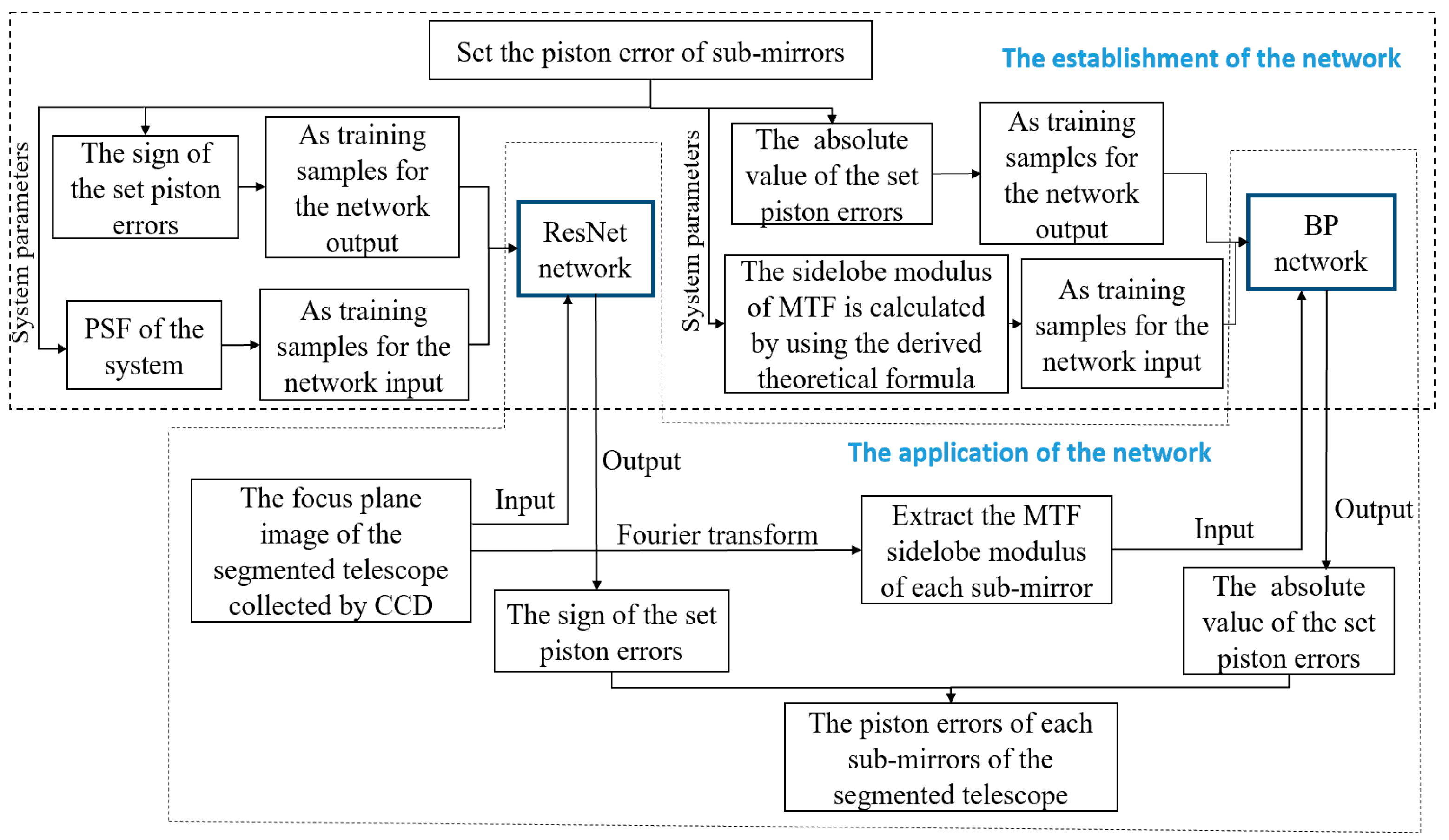
The principle of piston error detection method based on the hybrid neural network proposed in this paper is shown in
Figure 1. It mainly includes using Resnet network to detect the sign of piston error from the focal plane degradation image and using BP neural network to detect the absolute value of the piston error from the system MTF. In this part, we first describe the acquisition of focal plane degradation image and the establishment of theoretical relation between system MTF and piston error value of sub-mirrors, then the principle and procedure of piston error detection using the hybrid neural networks are introduced.
2.1. The acquisition of focal plane degradation image
For a segmented telescope like Keck, which all of the sub-mirrors are assumed to have the same shape and are perfect without high-order aberrations except pistons and tip-tilts. Thus, the generalized pupil function (GPF) can be shown as:
where
,
and
are the first three terms of the Zernike polynomials,
,
and
are the corresponding Zernike polynomial coefficients of the
nth sub-mirror respectively,
is the coordinate vector in pupil plane ,
is the is the binary function of sub-aperture and
N is the total number of sub-mirrors.
Based on the principle of Fourier optics, the relationship between the point spread function (PSF) of the system and the GPF is:
where
is the coordinate vector in the image plane,
is the wavelength of input light and
denotes the Fourier transform. When the input light is not monochromatic light, and is centered at
with the bandwidth
, the PSF is defined as:
where
is PSF weight of different wavelengths, assuming
.
According to the Fourier optics principle, the focal plane degradation image of the system is the convolution of the observation object and the system PSF, hence for an ideal point source observation target, the system focal plane image can be equivalent to the system multi-wavelength PSF. Combined with the three formulas given above, the focal plane degradation image of the segmented telescope for a point source observation target with broadband illumination can be acquired. The following figures show the corresponding simulation results for a segmented telescope composed of two sub-pupils.
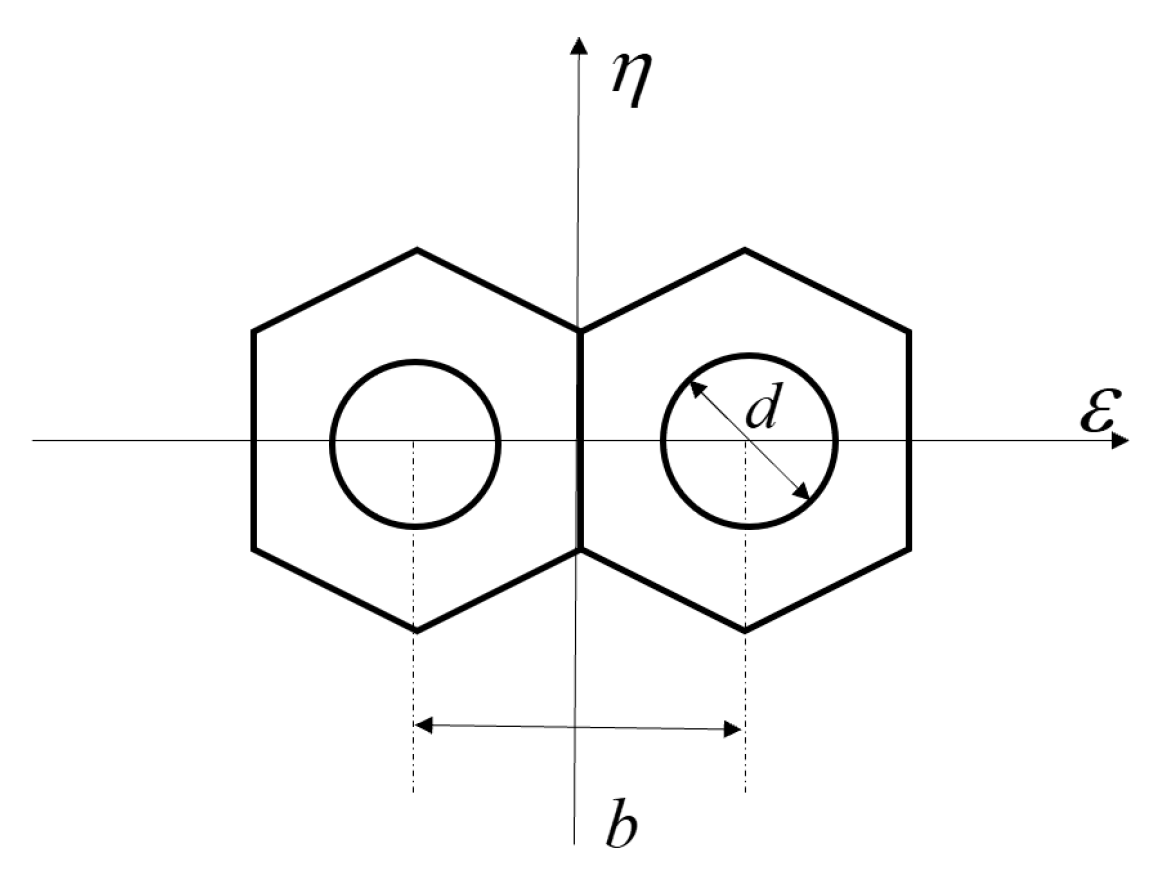
Figure 2 shows the segmented optics system model. A mask with two circles was set on the exit-pupil plane of the primary mirror to fragment the pupil, so the sidelobes of the system MTF can be separated from its main peak. And
b is the distance between the center of the two circle pupils on the mask,
d is the diameter of the circle pupil. We set up this optical system in MATLAB, the sampling grid of the exit pupil plane is set as 256×256 pixels, the pixel size of the CCD is 3.5 μm and the F# of the optical system is 8. Thus, the circumscribed circle diameter of the single hexagonal sub-mirror is 59 pixels, the diameter of the circle on the mask is18 pixels and the distance between the centers of the two circles is 52 pixels to satisfy the Nyquist sampling criterion. The central wavelength of the input broad light is 632.8 nm and its bandwidth is 20 nm. Half of the coherent length of this input broadband light is
So, the effective detection range of the proposed method is [-10~10] um.
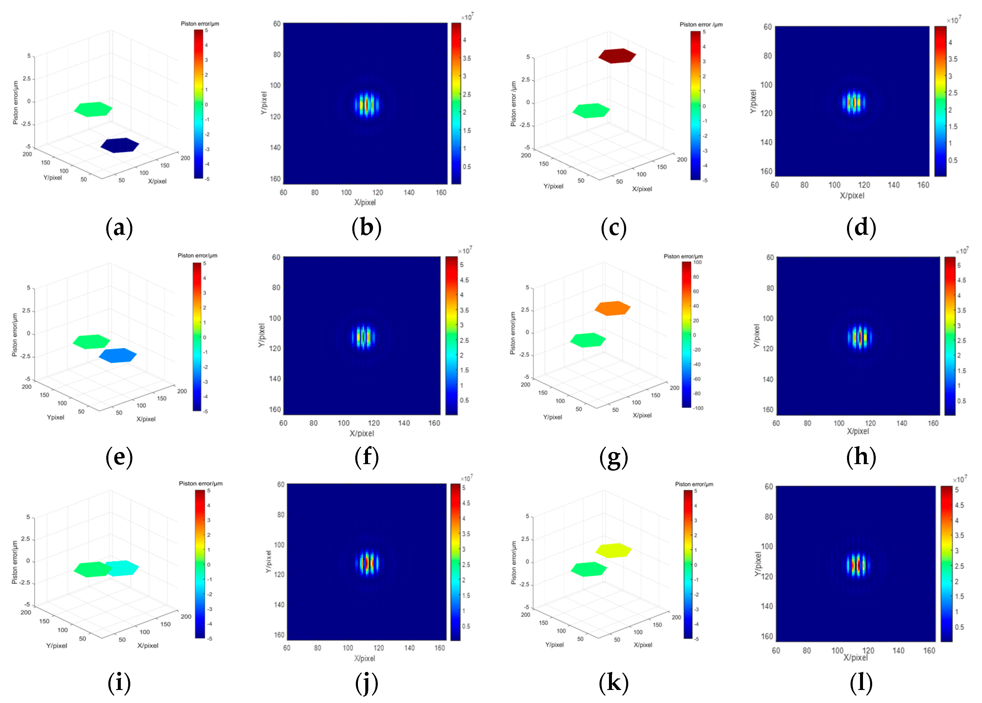
Different piston errors are introduced to the right sub-pupil while the left sub-mirror is set as the reference mirror. Several groups of the introduced piston error and corresponding system focal plane degradation images are shown in
Figure 3. We can see that piston errors with the same absolute value but opposite sign corresponds to different focal plane degradation images.
2.2. Theoretical relation between system MTF and piston error
For a segmented telescope with a mask set on the exit-pupil plane and the observation target is a point source with broadband illumination, there is a determined theoretical relationship between the system MTF and piston errors of sub-mirrors based on Fourier optics. Junlun Jiang et al. have deduced the formula in detail and presented their work in paper [
15]. Based on their work, we further deduced the theoretical relationship and briefly introduce the derivation process.
For a segmented system shown in
Figure 2, the GPF is
where
is the binary shape function of the hexagon segment,
stands for circle function, the phase difference between the two segments is
,
is the observation wavelength,
is the piston error between the two sub-mirrors. When the input light centered at
has a broad spectrum
, based on Equation (3) and (4), the system PSF can be written as
where
is first order Bessel function and
is divided into
n intervals equally since a differential summation approximation is used to replace the integral calculation. The complex OTF of input broadband light is 2D Fourier transform of the PSF in Equation (6), which is shown as
where
is the spatial frequency in the
and
direction respectively,
is the OTF of a single circle aperture diffraction system given by
among which
is radial coordinate on the frequency plane,
is the system cut-off frequency,
is focal length of the imaging lens. Performing modulus operation to OTF, the MTF of the system can be obtained. Based on Equation (7), the sidelobes of MTF can be extracted out and shown as
Since the value of the MTF central peak is 1, thus the peak height value of the MTF sidelobe with piston error is
We can see that the peak height of the MTF sidelobe is only related to the number of sub-pupils of the segmented telescope, input wavelength and piston error between segments. So, the modulus of MTF sidelobe can be easily calculated when the piston error is known.
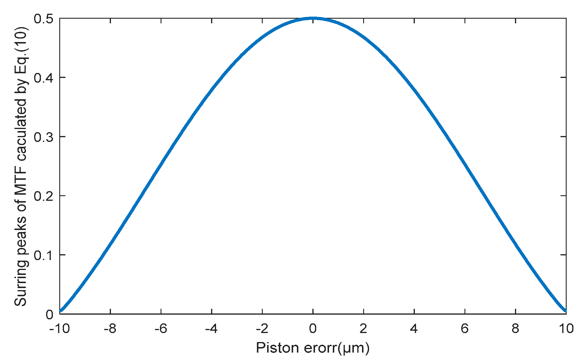
Figure 4 shows the values of the MTF sidelobes calculated from Equation (10) aimed for the two sub-mirrors segmented system described in
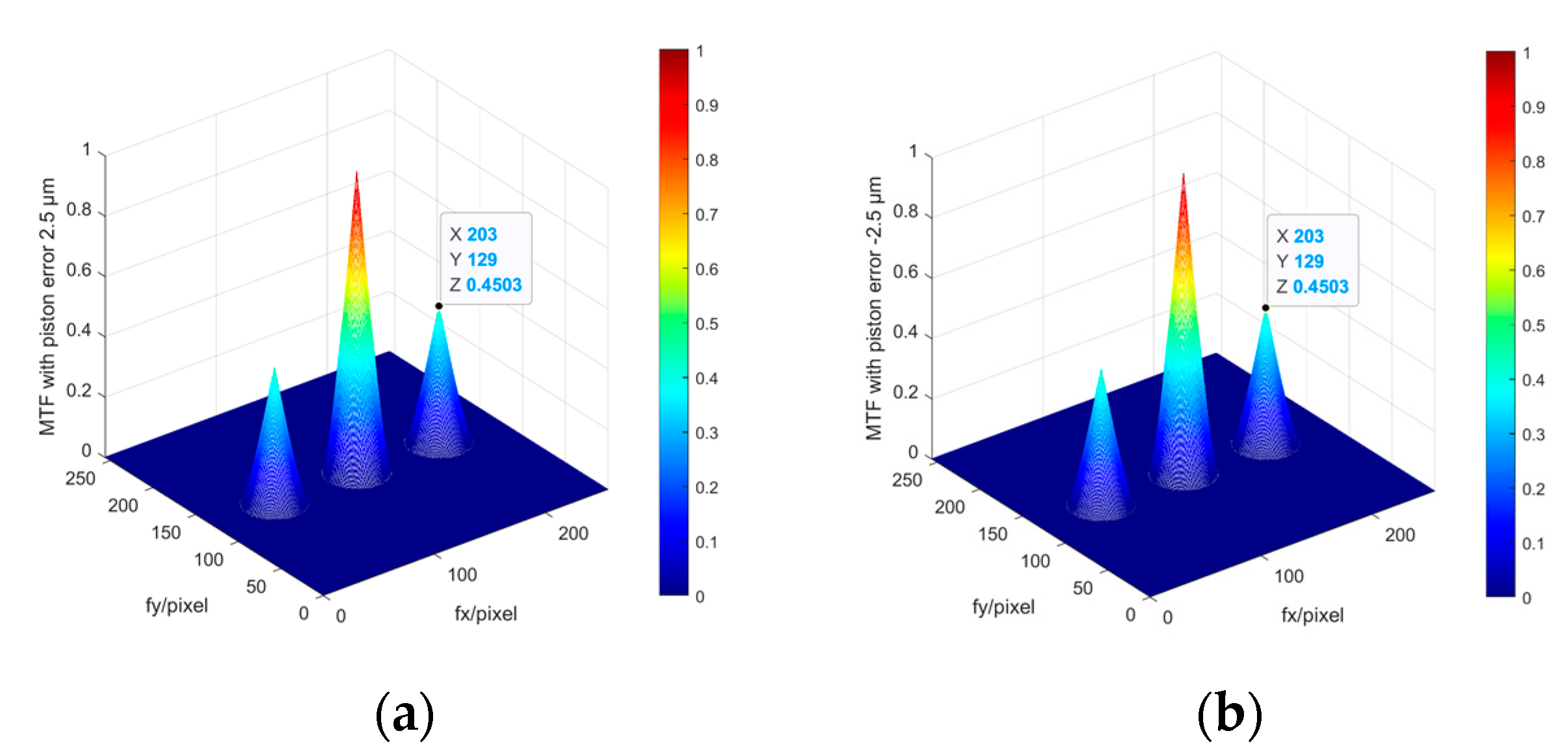
Section 2.1. It can be seen that the value of MTF sidelobe is an even function for the piston errors, the same absolute values of piston errors with opposite signs have the same MTF sidelobes. The MTFs simulated from MATLAB shown in
Figure 5 also prove this point. Therefore, this method could not identify the specific spatial relative positions of each sub-mirror while can only measure the absolute value of the piston error.
2.3. Use Resnet network to detect the sign of piston errors from focal plane images
Using neural network to solve the aberrations of optics system from focal plane image is essentially a process of classifying the degraded images of the focal plane with the aberration coefficient as the label. Resnet network proposes a unique residual module, which realizes identity mapping through short circuit hopping, and is more sensitive to data fluctuations, thus it is more suitable for building mapping models from image to data. At the same time, the network solved the gradient loss problem caused by network deepening and effectively improves the classification accuracy. However, when the required detection range is very wide and the detection accuracy is quite high, for the large aperture and super large aperture segmented telescopes, the number of network classification increases explosively, which greatly increases the network size and training difficulty. Therefore, the Resnet network in this paper is only used to detect the positive and negative sign of piston errors.
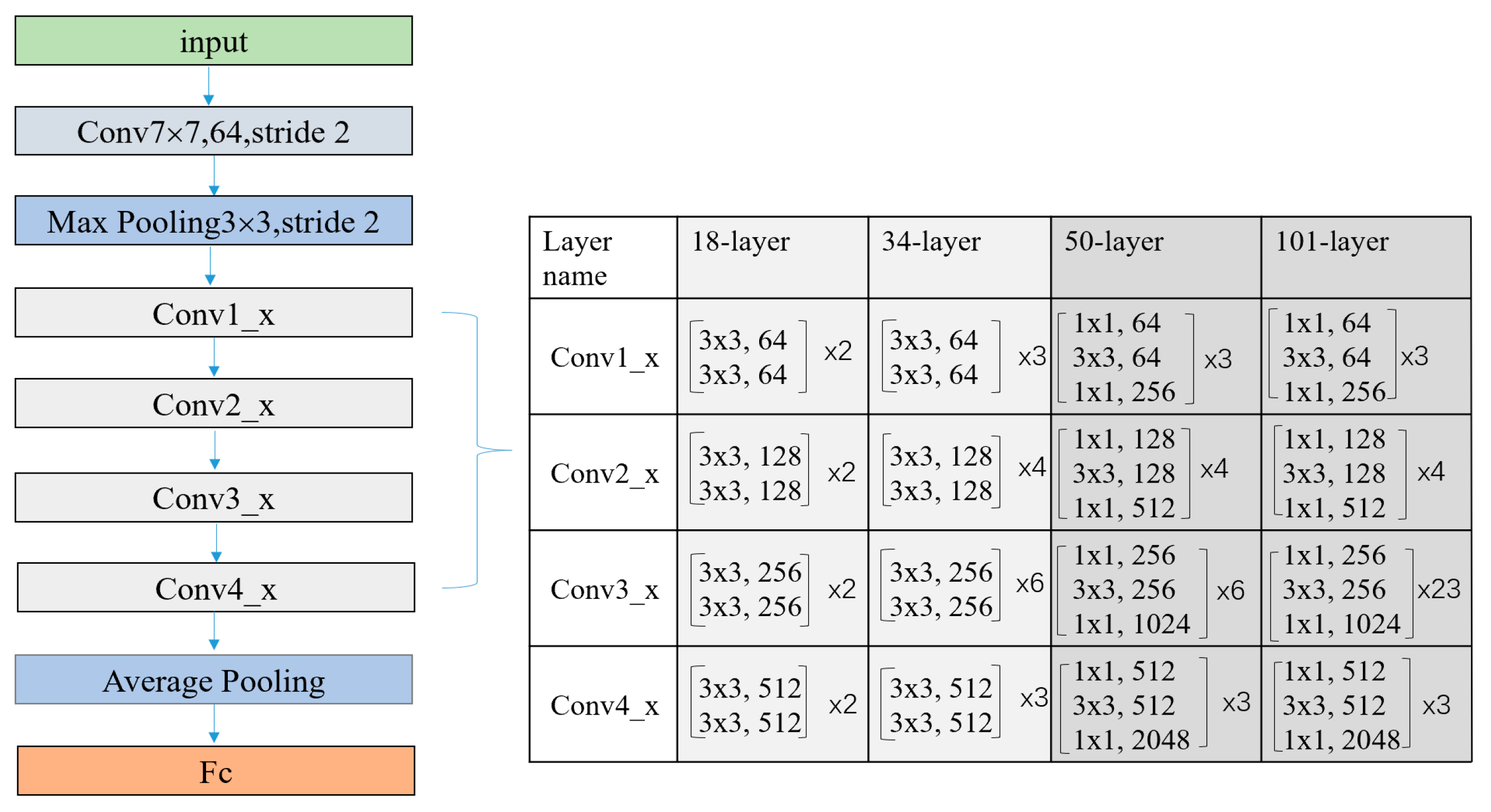
The specific Resnet network structure is shown in
Figure 6, here presents four different Resnet networks with depths of 18, 34, 50, and 101, the difference in depth is due to the using of different numbers of residual units in modules from conv1 to conv4. The structure of residual units with different depths is also different.
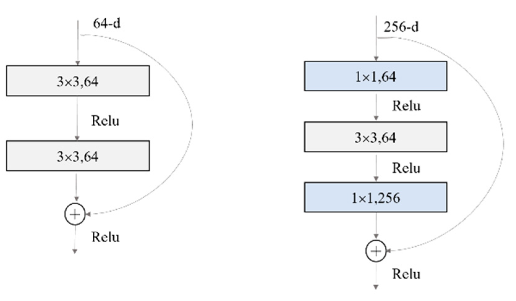
Figure 7 shows two different residual units. Please note that the full connection layer of the network needs to be modified to adapt the vector dimension of the output piston error.
2.4. Use BP network to detect the absolute value of piston errors from MTF
According to Equation (10), when the system parameters are determined and the piston errors are given, the sidelobes of the system MTF can be directly obtained. However, when the values of the MTF sidelobes are obtained, it is very difficult to use Equation (10) to solve the piston errors in reverse. Junlun Jiang et al. utilized piecewise quartic polynomials to fit the theoretical relationship, but different polynomial coefficients are needed to be constructed in different piston error detection ranges, so the implementation is complicated, and most importantly their method cannot distinguish the sign of piston error. In our work, a BP network is used to learn the mapping relationship between the absolute value of piston error and MTF sidelobes. When the network training is completed and the value of the MTF sidelobes is input to the network, the absolute value of the corresponding sub-mirror piston error can be directly output.
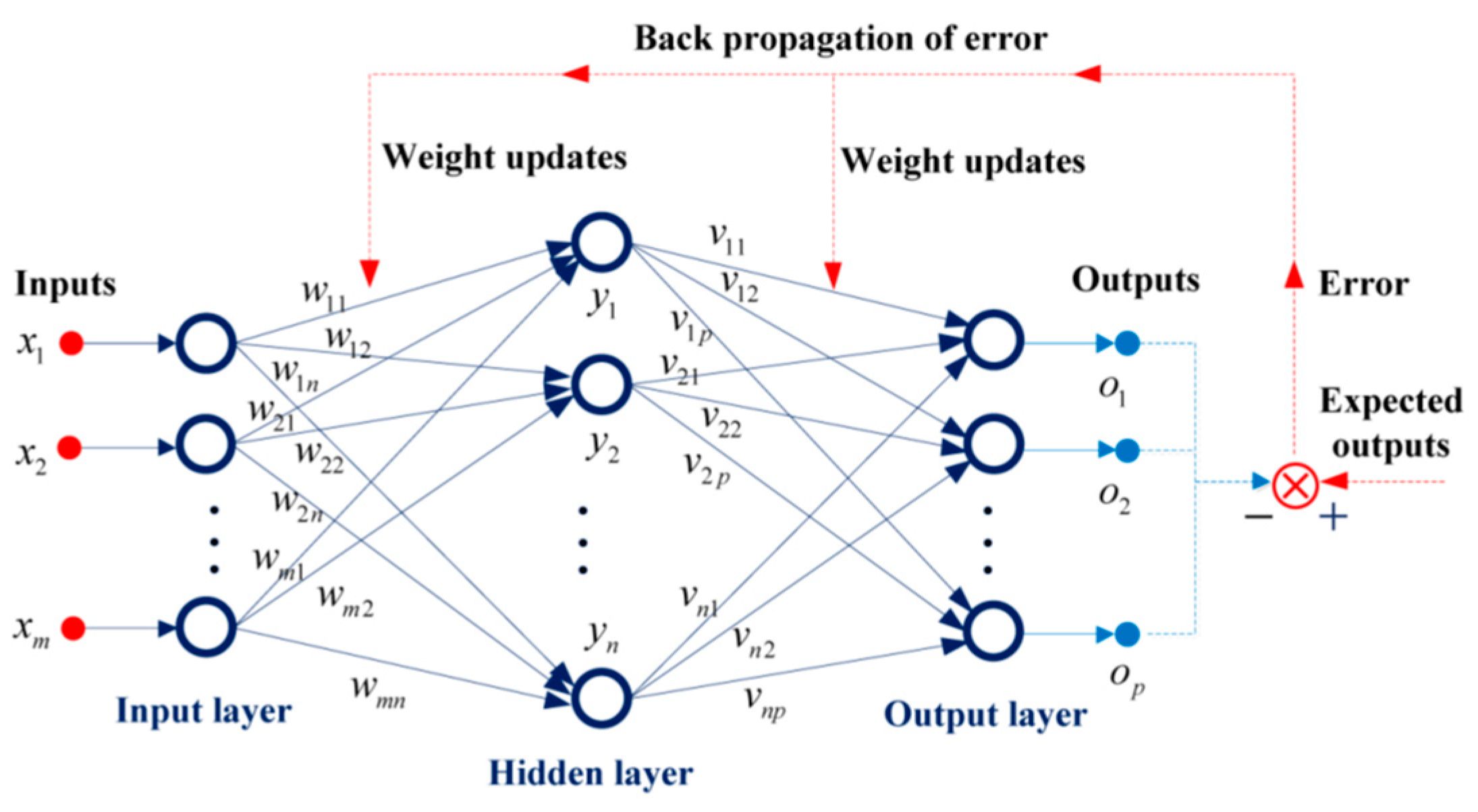
The structure diagram of BP neural network is shown in
Figure 8, the BP network algorithm can be divided into two steps: forward propagation and back propagation. In the forward propagation process, the input signal of the input layer is propagated to the output layer through the hidden layer, then the actual outputs are obtained. In the back propagation process, the difference between the actual output and the expected output of the network is taken as the error signal, and the error signal is propagated layer by layer from the output layer to the input layer, and the weights and thresholds of the network are adjusted by a certain algorithm. Through one forward propagation and one back propagation, one update of network parameters can be realized. The network training process is to continually carry out forward propagation and back propagation, and update the network parameters until the error signals become smaller and smaller, and finally make the network accurately map the relationship between the input and output.
3. Simulation
Using the hybrid network proposed in this paper to detect the piston errors of sub-mirror consists of three steps. Firstly, establish the data sets for network training. Within the coherent length range of the input broadband light, multiple groups of piston errors are randomly generated and loaded onto the corresponding sub-mirrors. By taking the piston errors to the established simulation segmented optical system, the corresponding focal plane degraded images are generated for training the Resnet network which is used to detect the signs of piston errors. Then taking the absolute value of piston errors and optical system parameters into Equation (10), the values of MTF sidelobes can be obtained to train the BP network. Secondly, train the hybrid network. The generated focal plane degraded images and the signs of corresponding piston errors are used as input and output of Resnet network respectively, and with the cross-entropy loss function used as the index function of the network optimization, the Resnet network can be well trained through a certain optimization algorithm. Then the calculated values of MTF sidelobes and the absolute values of corresponding piston errors are used as input and output of BP network respectively and by setting up specific training algorithm, the BP network can also be well trained. Finally, after the hybrid network training is finished, by taking a degraded focal plane image into Resnet work, the signs of all sub-mirrors’ piston errors can be obtained. Then perform the Fourier transform to the focal plane image to get the values of MTF sidelobes and input them to the BP network, the absolute values of all sub-mirrors’ piston errors can be solved. One thing to note here is that the corresponding relationship between MTF sidelobe and its related sub-mirror should be established in advance, the absolute values of all the sub-mirrors’ piston errors can be measured simultaneously by one CCD broadband image. Thus, the measurement of the piston error with high precision and wide detection range can be realized by combining output of the two networks.
We first conduct simulation experiment analysis on the segmented telescope system composed of two hexagonal sub-mirrors as shown in
Figure 2. Then the simulation experiments are processed to multiple sub-mirrors (N>2) segmented telescope system which is composed of four hexagonal sub-mirrors. In the end, we do some comparation work between our method and the work published by MA XIAFEI et al in paper [
17], since they also used a single wide-band image of a point source to perform piston sensing by neural network.
3.1. Simulation on two sub-mirrors segmented telescope system
MATLAB software is used to build the simulation optical system model consisting of two hexagonal sub-mirrors as shown in
Figure 2. The specific system parameters are the same as those set in
Section 2.1. During the simulation experiment, the left sub-mirror of the system is set as the reference sub-mirror, and a series of piston errors are introduced on the right sub-mirror. Here, we firstly generate 60,000 sets of piston error in [-10~10]um randomly and 60,000 sets of focal plane degradation images are obtained by MATLAB simulation. Then by taking the corresponding piston errors into Equation (10), we can obtain 60000 sets of the MTF sidelobes values. The generated data sets are divided into three groups, namely training set, verification set and test set. The proportion of the three parts is 65%:20%:15%, namely 39,000 groups for training, 12,000 groups for verification, and 9000 groups for testing.
Then the network training can be processed based on the obtained data sets. Here we build a Pytorch deep learning environment on an Ubuntu server equipped with Nvidia GeForce 2080 GPU to achieve the training of the hybrid networks. The Resnet network is first trained to predict the signs of piston error. The focal plane degradation images shown in
Figure 3 is used as the input of Resnet network, and the signs of the piston errors are used as the output of Resnet network with label ‘0′ representing positive and label ‘1′ representing negative. Each network is trained with 300 epochs, the batch size is set as 32 and the cross-entropy loss function is used as the index function. The network parameters are updated by back-propagation and the evaluation of the trained network is realized through the verification set. At the same time, some strategies are used to improve network efficiency such as batch normalization used between convolutional layers to prevent gradient disappearance.
Four Resnet networks with different depths including Resnet18, Resnet34, Resnet50 and Resnet101 are trained here to test their prediction accuracy of the piston error signs.
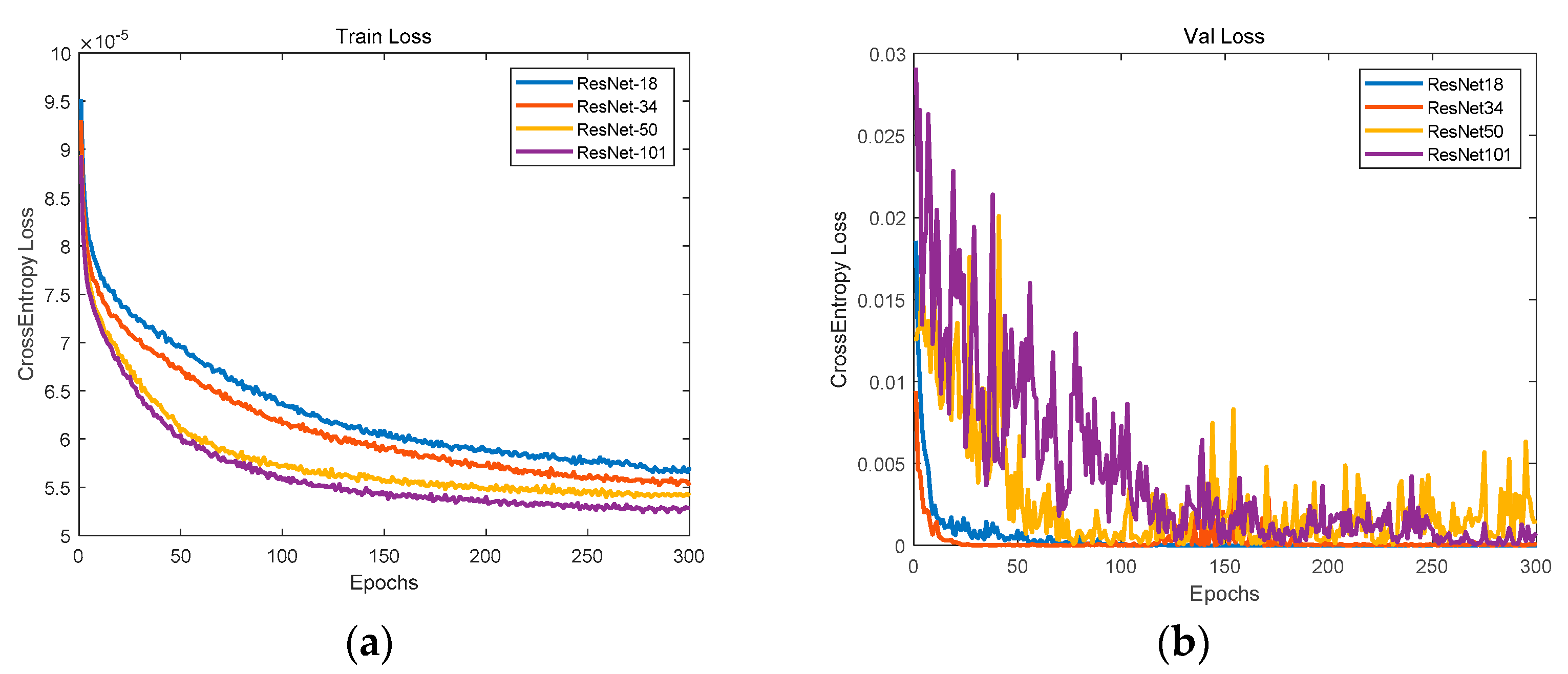
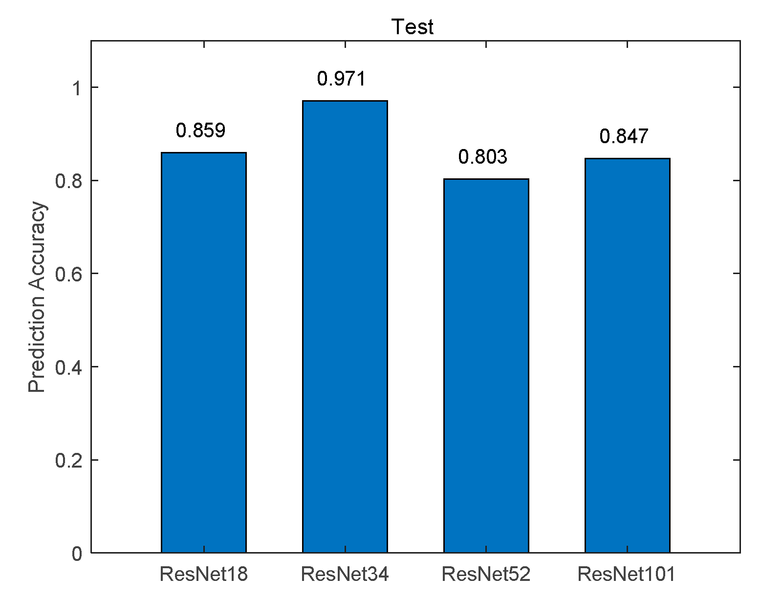
Figure 9 shows the loss functions of the training set and verification set, where the horizontal axis represents the number of training and the vertical axis represents the cross-entropy loss function. We can see that after 300 rounds of training, the loss function gradually declines and finally reaches a stable state. From the loss function curve of the training set, the Resnet networks fitting degree gradually increases with the deepening of the network, but from the loss function curve of the verification set, with the deepening of the network, the generalization ability of the network Resnet50 and 101 are much lower than that of Resnet18 and 34, resulting in the loss function oscillation of the verification data set. Then we use the test data set to verify the piston error sign prediction accuracy of the four Resnet networks with different depths, the test result is given by
Figure 10 where the prediction accuracy of the piston error signs is given by the number of correct predictions in the test set divided by its total number . From
Figure 9 and
Figure 10, we can see that Resnet34 network has the highest generalization ability and the highest prediction accuracy. Therefore, the optimal model for prediction the signs of piston error for the two sub-mirror segmented system is Resnet34 network.
Then, the BP neural network is trained to solve the absolute value of the piston errors. The values of MTF sidelobes shown in
Figure 5 is taken as the input of the network, and the corresponding absolute value of the piston error is taken as the output of the network. The number of neurons in the hidden layer of BP network is set as 10, the node transfer function of the hidden layer is logsig function, the node transfer function of the output layer is purelin function, and the learning training function is traindx which is a variable learning rate momentum algorithm. The training results of the network are shown in
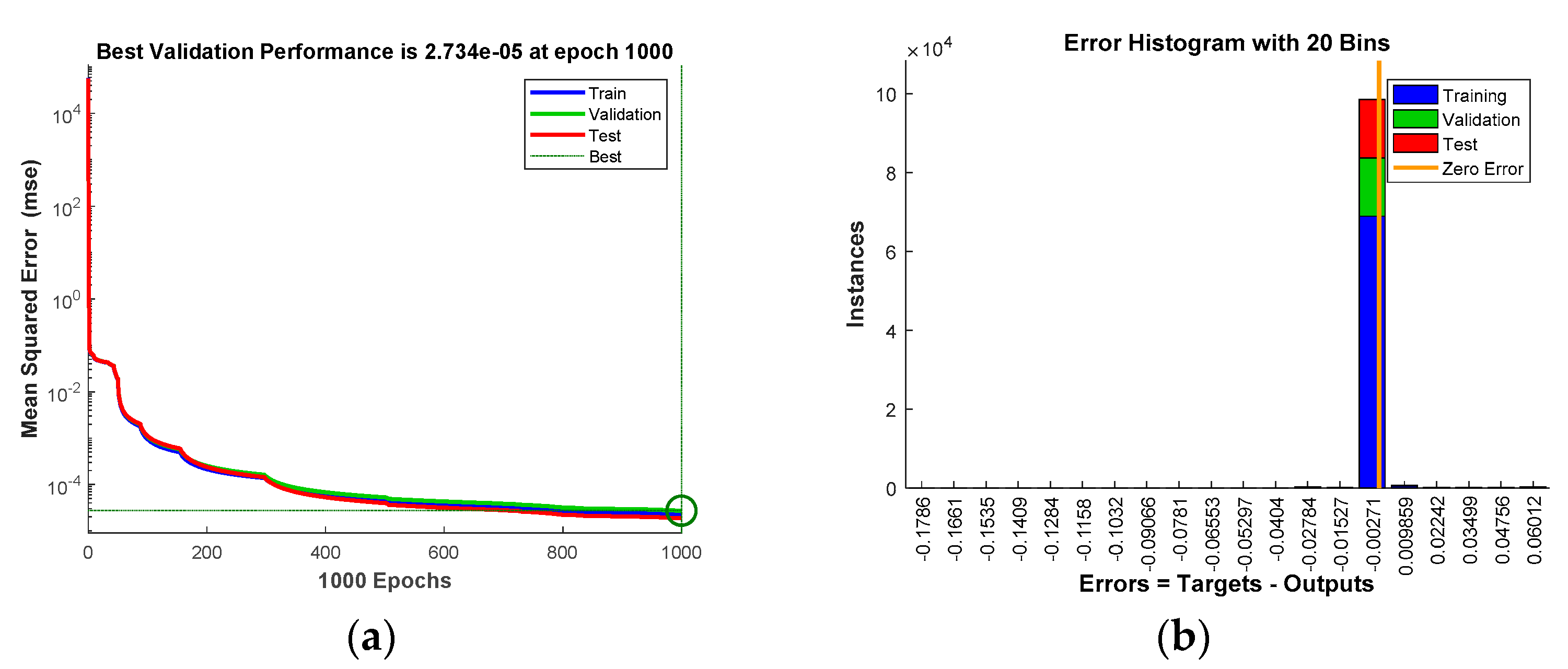
Figure 11.
Figure 11a shows the loss function changing with the number of iterations and
Figure 11b provides the error distribution between the expected value and the actual network output value in the form of a histogram. According to the training results, the RMSE between the expected value and the actual output of the network in the training set, the verification set and the test set are 2.235×10⁻⁵μm, 2.734×10⁻⁵μm and 1.873×10⁻⁵μm respectively. It is proved that the BP neural network proposed here can be used to calculate the absolute value of piston error with high precision.
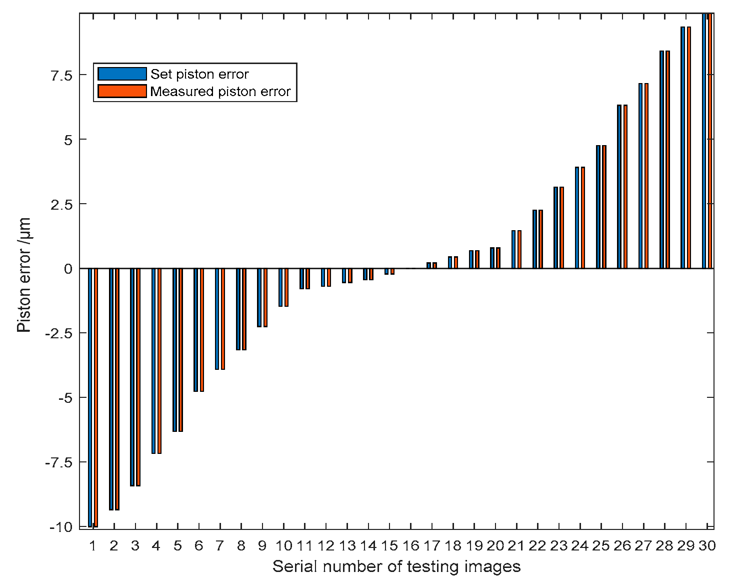
After the hybrid network is well trained, the actual network performance can be tested. Here, another 500 new focal plane images are generated from the simulation optical system for testing. In order to approximate the actual imaging environment, Gaussian distribution noise with the mean of 0 and variance of 0.05 is introduced into the simulated PSF images. And since tip-tilt errors cannot be completely corrected, the tip-tilt errors are also added to each sub-mirror during the generation of the focal plane degradation image, where the total RMSE value of the added tip-tilt errors is 0.01λ. Since we only consider the co-phase errors like Keck where all sub-mirrors are assumed to have the same shape and are perfect without high-order aberrations except pistons and tip-tilts, thus higher order aberrations of each sub-mirror are not considered here.
Figure 12 shows 30 groups of experiment results randomly selected from the whole 500 groups. The piston error detection accuracy is given by the difference between the measured piston error and the set piston error. According to the error analysis, the RMSE of the difference values of the 30 experimental results is 1.26nm where the RMSE is defined as
,
N is the number of experiment groups.
Figure 13 shows the piston error detection results of all the 500 groups of simulation experiments, among which the difference of the detection results within 10nm is 494 groups, and the RMSE of the 494 groups is 1.76nm. The left 6 groups of difference values of the piston error detection results are very large, far greater than the mean difference values of the 494 groups of piston error detection results. This is because the signs of piston errors are predicted wrongly by the Resnet network, and the measurement error is basically twice of the set piston error.
Figure 13a shows the piston error measurement results of all 500 the groups of simulation experiments,
Figure 13b shows the measurement errors of these 494 groups in the form of a scatter plot, and
Figure 13c takes the absolute value of measurement error as the horizontal coordinate to give the statistical results of the 500 groups of piston error detection experiments. It can be seen that the detection range of this method is very wide, ranging from -10μm to 10μm reaching the whole coherence length of the input broadband light. The measurement accuracy is very high, and the probability of measurement error less than or equal to 10nm is as high as 98.8%.
3.2. Simulation on four sub-mirrors segmented telescope system
In this part, we use a four sub-mirror segmented telescope system as an example to test the performance of the proposed algorithm on detecting the piston errors of multiple sub-mirrors (N>2) segmented telescope system at one time. When using Resnet network to detect the signs of piston errors of the multi-submirrors, the output of Resnet network is set to 2
(N-1), which corresponds to the piston error signs of all sub-mirror (except the reference sub-mirror). When BP network is used to solve the absolute value of the piston errors of multiple sub-mirrors through the MTF sidelobes, according to paper [
16], as for a segmented telescope system composed of
N sub-mirrors, there are
N2 sub-MTFs. In the spatial frequency domain, the
N sub-MTFs overlapped at the position where the center spatial frequency is zero to form the central peak, while the other
N (N-1) sub-MTFs distributed around the central peak to form the sidelobes. Every pair of sub-mirrors produce a pair of MTF sidelobes, the sidelobes symmetrically distributed on both sides of the central peak. If all of the sidelobes do not overlap, their amplitudes could be obtained at the same time by one CCD image, hence the absolute value of the piston errors of all sub-mirrors can be retrieved at the same time by inputting the peak height of sub-MTFs corresponding to each sub-mirror into the trained BP network. Combined the outputs of the two networks, the piston errors of all the segmented sub-mirrors can be solved at one time using a focal plane degradation image.
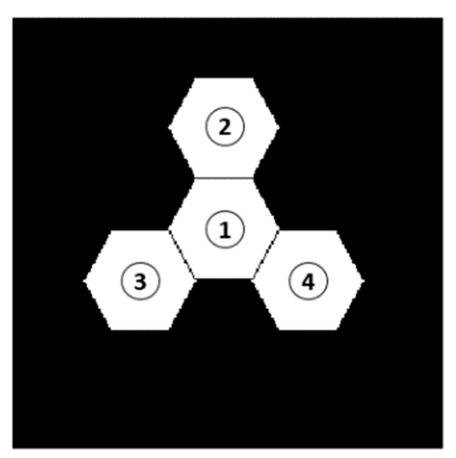
The established simulation model of four sub-mirrors segmented telescope system in MATLAB is shown in
Figure 14. The reason why the system model is built like this is to prevent the MTF sidelobes from being overlapped. Here the wavelength of input broadband light is also centered at 632.8 nm with 20 nm bandwidth. The No.1 sub-mirror is set as reference pupil and the piston errors randomly generated between -10 um and 10um are introduced on sub-mirrors No. 2, 3 and 4, thus the degraded focal plane images with different piston errors can be obtained.
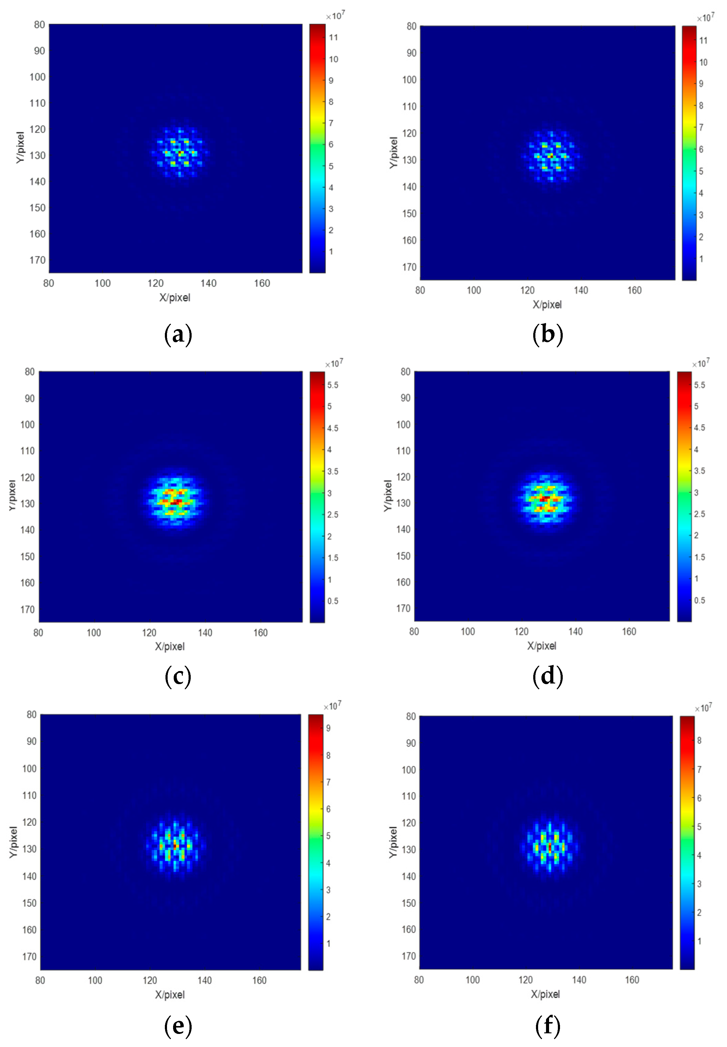
Figure 15 shows several degraded images on the focal plane corresponding to the several sets of introduced piston errors on multiple sub-mirrors.
Figure 14. Segmented telescope model composed of four sub-mirrors.
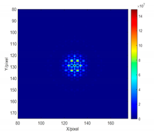
During the simulation experiment, 60000 sets of piston errors are randomly generated and introduced into the simulation optical system, 60000 groups of focal plane degradation images can be obtained. The focal plane degradation image is used as the input of the Resnet network, and the signs of the piston errors of the 3 sub-mirrors are used as the output, here the Resnet network output is divided into eight categories. When constructing the labels of network outputs, we use 0 to indicate a positive sign and 1 to indicate a negative sign, which is similar to the binary encoding process and shown in the following table. The other setting parameters and training process of Resnet network are the same as those of the two sub-mirror system, which will not be repeated here.
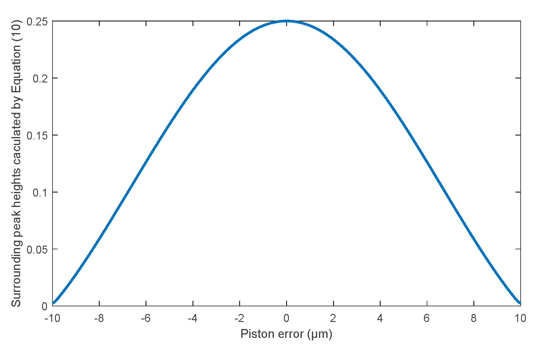
When training the BP network, we take the number of sub-mirrors N=4, the wavelength of the input broadband light, and 60000 sets of piston errors generated randomly into Equation (10). We use the modulus values of MTF sidelobes calculated directly from Equation (10) as the input matrix, while the corresponding piston errors are used as the output matrix of the training network.
Figure 16 shows the relationship between the modulus values of MTF sidelobe directly calculated by Equation (10) and the piston error of sub-mirror in the form of a curve. The obtained 60000 data sets are used to train the BP network. The parameters setting and the training process of BP network are the same as that of the two sub-mirrors segmented optical system, which also will not be repeated here.
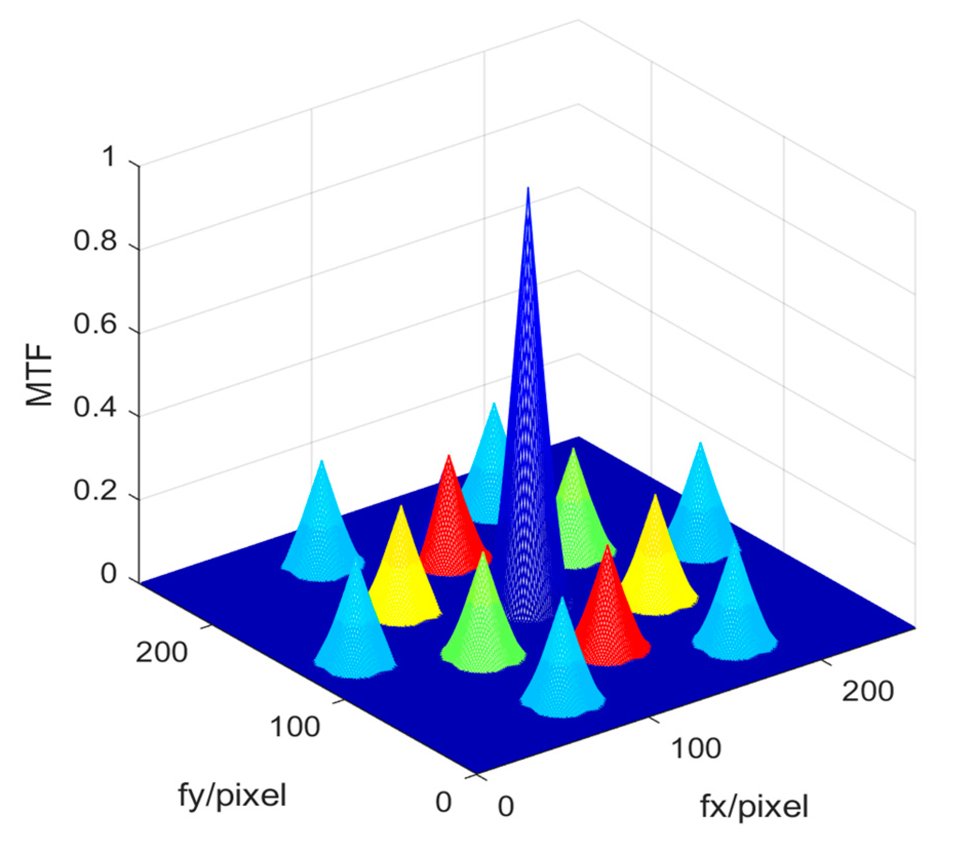
In order to solve the absolute value of the piston errors of the multiple sub-mirrors simultaneously from one focal plane image based on the well-trained BP network, the mapping relationship between sub-MTFs and their corresponding sub-mirrors must be established in advance. The system MTF of the four sub-mirrors segmented optical system in this experiment include a central main peak and 12 (N (N−1) =4× (4-1) =12) sidelobes, which is shown as
Figure 17 with color-marks. When sub-mirror No. 1 is set as the reference mirror, sub-mirror No. 2 produces the red sub-MTFs, sub-mirror No. 3 produces the green sub-MTFs, and sub-mirror No. 4 produces the yellow sub-MTFs. The six peripheral blue sub-MTFs are modulated by piston errors of the other two sub-mirrors simultaneously except the reference mirror, which cannot be used to measure the piston error of each sub-mirror. The establishment of mapping relationship between the sub-mirror and the corresponding MTF sidelobes can be referred to the paper [
16]. It should be noted that the relationship between the MTF sidelobes and the absolute value of piston error of each sub-mirrors is the same (as shown in
Figure 16), thus it is not necessary to conduct training for all the three sub-mirrors at one time, but to use one data set to train a single BP network, then by inputting the modulus of sub-MTF corresponding to each sub-mirror directly, the piston error absolute value of each sub-mirror can be obtained. This can reduce the difficulty of network training and improve the detection accuracy.
After the hybrid network is well trained, the actual performance of the network should be tested. We randomly generate multiple sets of piston errors in the range of [-10 10]um and introduce them into sub-mirrors No. 2, 3 and 4 separately, then the focal plane degradation image can be obtained. In order to be closer to the real imaging situation, Gaussian noise with mean 0, variance 0.05 and tip-tilt errors with RMSE 0.01λ are added to the generated the focal plane degradation images.
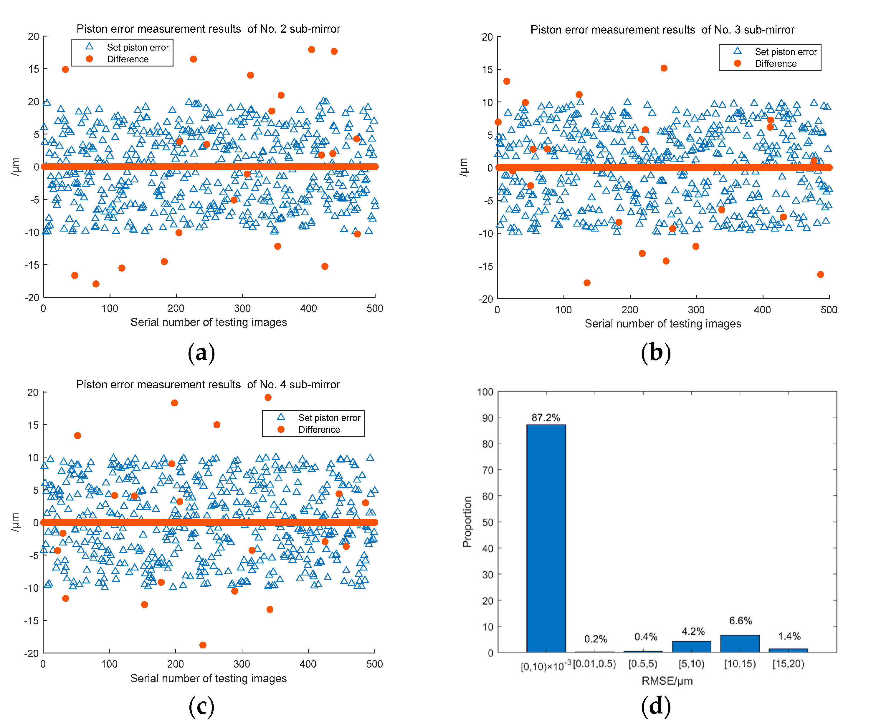
We also generated 500 focal plane images of the system for testing, and the test results are shown in
Figure 18. The piston error detection results of sub-mirror No.2, 3, 4 are shown in
Figure 18a, 18b, and 18c respectively,
Figure 18d shows the distribution histogram of the RMSE values of the all three sub-mirrors piston errors detection results in the 500 groups. It can be seen that with the increasement of the number of sub-mirrors, the classification number of Resnet network becomes more and the detection accuracy of the signs of piston errors decreased, but the detection accuracy of BP network has on change. The probability of measurement error less than or equal to 10nm can still be maintained above 85%.
3.3. Comparation work
Finally, we compare our method with the work published by MA XIAFEI et al in paper [
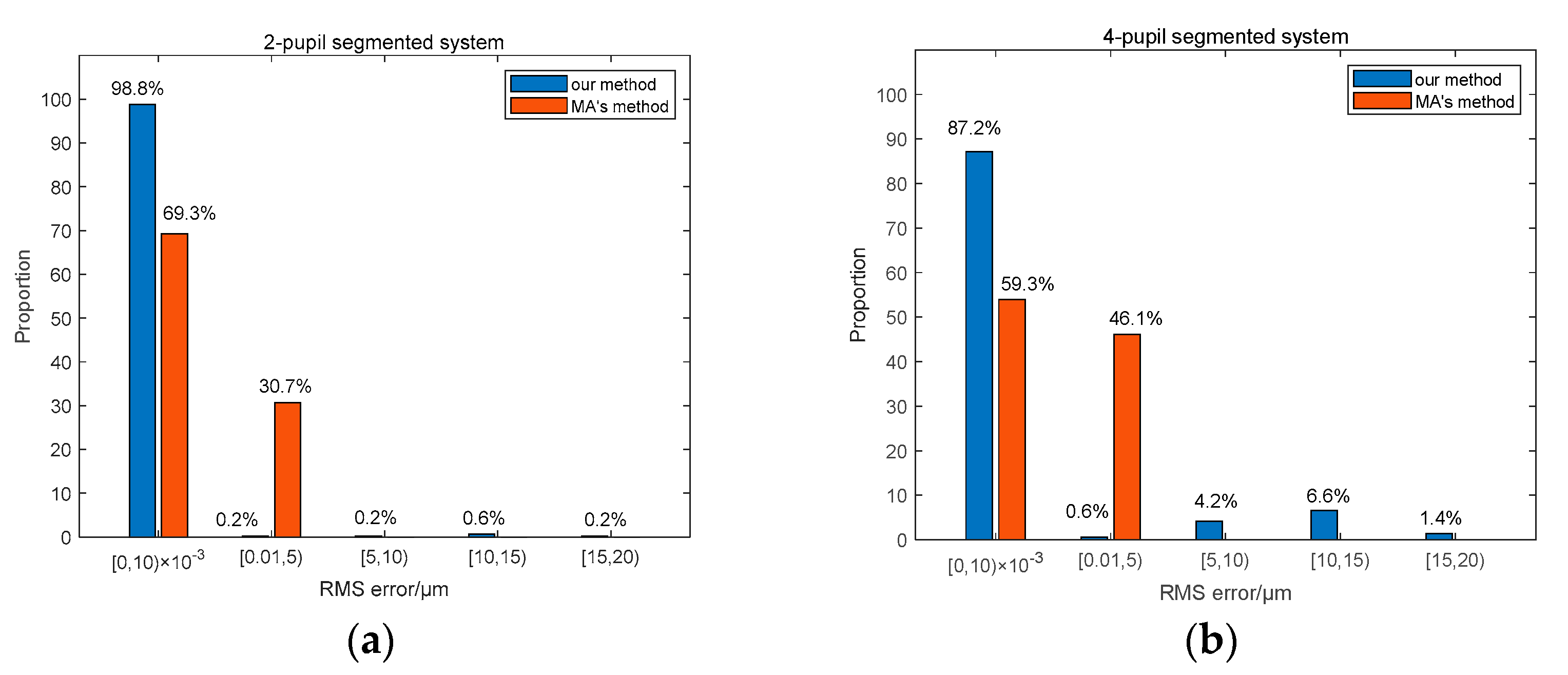
17], because they also used a single wide-band image of a point source to perform piston sensing by neural network. But they did not establish the theoretical relationship between MTF and piston error based on Fourier optics, while a DCNN network is used to directly learn the mapping relationship between the focal plane degradation images and the piston errors of sub-mirrors, and finally the piston error detection is realized based on a single neural network. The comparison experimental results aimed for the two-pupil segmented system and the four- pupil segmented system are shown in
Figure 19. It can be seen that the piston error detection accuracy of the method proposed by us is generally higher than that of the method proposed by MA et al. This is because we construct the theoretical relationship between the system MTF and the piston errors and use the modulus of MTF sidelobes as the network input, while MA et al directly use the focal plane image as the input of the network. However, the maximum value of piston error detection difference of our proposed method is much larger than that of MA’s method. This is because when using Resnet network to detect the signs of the piston error wrongly, the detection difference value is almost the twice of the set piston error value. So how to improve the detection accuracy of the signs of piston error is quite important in our next work.
4. Discussion
This paper proposed a piston error detection method based on a hybrid neural network, it can realize a wide-range and high-precision measurement of all sub-mirrors’ piston errors by using a single wide-band image of a point source observation target at one time. Its detection range can reach the entire coherent length of the input broadband light. For the 2-pupil segmented system, the proportion of detection accuracy within 10nm is 98.8%, and for the 4-pupil segmented system, the proportion of detection accuracy within 10nm is 87.2%. Due to the establishment of the theoretical relationship between the piston errors of the sub-mirror and the MTF of the system, each network’s structure of the hybrid network is relatively simple, which greatly reduces the network size and training difficulty, and ensures that the proposed method is simple to be implemented. By using the method proposed in this paper, the piston error detection of the segmented optics system no longer need to be divided into coarse phasing and fine phasing where different hardware devices are needed. This greatly reduces the detection complexity and cost and provides a relatively simple and feasible piston error detection method for the large aperture segmented telescope optics system.
Author Contributions
Conceptualization, Dan. Yue. and Yahui. Chuai.; methodology, Dan. Yue.; software, Pengcheng. Song.; validation, Pengcheng. Song. and Cong shuai. Wang.; writing—original draft preparation, Dan. Yue.; writing—review and editing, Dan. Yue. ; funding acquisition, Dan. Yue. All authors have read and agreed to the published version of the manuscript.
Funding
This research was funded by Science and Technology Department project of Jilin Province, 20220101027JC; Science and Technology Research Project of Education Department of Jilin Province, JJKH20220740KJ; National Natural Science Foundation of China 61905023 and 62204024.
Data Availability Statement
Data is unavailable due to privacy.
Conflicts of Interest
The authors declare no conflict of interest.
References
Disclaimer/Publisher’s Note: The statements, opinions and data contained in all publications are solely those of the individual author(s) and contributor(s) and not of MDPI and/or the editor(s). MDPI and/or the editor(s) disclaim responsibility for any injury to people or property resulting from any ideas, methods, instructions or products referred to in the content.
- P. Y. Bely, The design and construction of large optical telescopes. Springer Science & Business Media, 2003.
- L. Noethe, History of mirror casting, figuring, segmentation and active optics. Experimental Astronomy 2009, 26, 1–18. [CrossRef]
- J. M. Hill, R. Ragazzoni, A. Baruffolo, Prime focus active optics with the Large Binocular Telescope. Proceedings of SPIE-The International Society for Optical Engineering 2008, pp. 70121M–1-70121M-10.
- G. Chanan, M. Troy, F. Dekens, et al, Phasing the mirror segments of the Keck telescopes: The broadband phasing algorithm. Applied Optics 1998, 37, 140–155. [CrossRef]
- G. Chanan, C. Ohara, M. Troy, Phasing the mirror segments of the Keck telescopes II: the narrow-band phasing algorithm. Applied Optics 2000, 39, 4706–4714. [CrossRef] [PubMed]
- S. Esposito, E. Pinna, A. Tozzi, et al, Co-phasing of segmented mirrors using the pyramid sensor. Proceedings of SPIE-The International Society for Optical Engineering 2003, 5169, 72–78.
- S. Esposito, E. Pinna, A. Puglisi, et al, Pyramid sensor for segmented mirror alignment. Optics Letters 2005, 30, 2572–2574. [CrossRef] [PubMed]
- R. P. J. Angel, Ground-based imaging of extrasolar planets using adaptive optics. Nature 1994, 368, 203–207. [CrossRef]
- M. V. Dam, B. A. Mcleod, A. H. Bouchez, Dispersed fringe sensor for the Giant Magellan Telescope. Applied Optics 2016, 55, 539–547. [CrossRef]
- Y. H. Meng, S. Y. Xu, B. Q. Xu, A segmented mirror common phase method based on dispersion fringe sensing technology. Acta Optica Sinica 2016, 36, 140–150.
- F. Baron, I. Mocoeur, F. Cassaing, et al, Unambiguous phase retrieval as a co-phasing sensor for phased array telescopes. Journal of the Optical Society of America. A Optics 2008, 25, 1000–1015. [CrossRef] [PubMed]
- G. H. Ju, C. X. Yan, Y. Dan, et al, Field diversity phase retrieval method for wavefront sensing in monolithic mirror space telescopes. Applied Optics 2017, 56, 4224–4237. [CrossRef]
- D. Yue, S. Y. Xu, H. T. Nie. Co-phasing of the segmented mirror and image retrieval based on phase diversity using a modified algorithm. Applied Optics 2015, 54, 7917–7924. [CrossRef]
- D. Yue, S. Y. Xu, H. T. Nie et al. Error Analysis and Elimination Method of Wave Front Detection by Phase Difference Method. Acta Optica Sinica 2016, 36, 95–105.
- J. Jiang, W. Zhao, Phasing piston error in segmented telescopes. Optics Express 2016, 24, 19123–19137. [CrossRef] [PubMed]
- W. Zhao, Q. Zeng, Simultaneous multi-piston measurement method in segmented telescopes. Optics Express 2017, 25, 24540–24552. [CrossRef] [PubMed]
- X. Ma, Z. Xie, H. Ma, et al, Piston sensing of sparse aperture systems with a single broadband image via deep learning. Optics Express 2019, 27, 16058–16070. [CrossRef] [PubMed]
Figure 1.
The principle of piston error detection method based on the hybrid neural network.
Figure 1.
The principle of piston error detection method based on the hybrid neural network.
Figure 2.
Two sub-mirrors segmented telescope with sparse circles configuration.
Figure 2.
Two sub-mirrors segmented telescope with sparse circles configuration.
Figure 3.
Piston errors and its corresponding system focal plane images (a) p=-5μm; (b) corresponding focal plane image with p=-5μm; (c) p=5μm; (d) corresponding focal plane image with p=5μm; (e) p=-2.5μm; (f) corresponding focal plane image with p=-2.5μm; (g) p =2.5μm; (h) corresponding focal plane image with p=2.5μm; (i) p=-1μm; (j) corresponding focal plane image with p=-1μm; (k) p=1μm; (l) corresponding focal plane image with p=1μm.
Figure 4.
The MTF sidelobes calculated from Equation (10) corresponding to different piston errors of the two sub-mirrors segmented telescope system.
Figure 4.
The MTF sidelobes calculated from Equation (10) corresponding to different piston errors of the two sub-mirrors segmented telescope system.
Figure 5.
MTFs simulated from MATLAB of the two sub-mirrors segmented telescope system (a) the system MTF with p=2.5um; (b) the system MTF with p=-2.5um.
Figure 5.
MTFs simulated from MATLAB of the two sub-mirrors segmented telescope system (a) the system MTF with p=2.5um; (b) the system MTF with p=-2.5um.
Figure 6.
The structural diagram of Resnet network.
Figure 6.
The structural diagram of Resnet network.
Figure 7.
Different residual elements.
Figure 7.
Different residual elements.
Figure 8.
The structural diagram of BP neural network.
Figure 8.
The structural diagram of BP neural network.
Figure 9.
The loss function curves of the four Resnet models: (a) Training data set; (b) validation data sets.
Figure 9.
The loss function curves of the four Resnet models: (a) Training data set; (b) validation data sets.
Figure 10.
The piston error signs prediction accuracy for the four Resnet models.
Figure 10.
The piston error signs prediction accuracy for the four Resnet models.
Figure 11.
Training results of the BP neural network for the two sub-mirrors segmented system: (a) Loss function; (b) error histogram.
Figure 11.
Training results of the BP neural network for the two sub-mirrors segmented system: (a) Loss function; (b) error histogram.
Figure 12.
Piston error measurement results by the proposed hybrid network.
Figure 12.
Piston error measurement results by the proposed hybrid network.
Figure 13.
Piston error detection results of the 500 test sets for the two sub-mirror segmented system (a) The whole detection results of the 500 test sets; (b) detection results after removing the 6 sets of outliers; (c) statistical histogram distribution of the piston error measurement difference.
Figure 14.
Segmented telescope model composed of four sub-mirrors.
Figure 14.
Segmented telescope model composed of four sub-mirrors.
Figure 15.
Degraded focal plane images of the four sub-mirror segmented system: (a) [p2 p3 p4] = [-2.5 0 5]μm; (b) [p2 p3 p4]=[2.5 0 -5]μm; (c) [p2 p3 p4]= [4 -7.5 10]μm; (d) [p2 p3 p4]= [-4 7.5 -10]μm; (e) [p2 p3 p4]=[9 0.6 2.75]μm; (f) [p2 p3 p4]=[-9 -0.6 2.75]μm.
Figure 15.
Degraded focal plane images of the four sub-mirror segmented system: (a) [p2 p3 p4] = [-2.5 0 5]μm; (b) [p2 p3 p4]=[2.5 0 -5]μm; (c) [p2 p3 p4]= [4 -7.5 10]μm; (d) [p2 p3 p4]= [-4 7.5 -10]μm; (e) [p2 p3 p4]=[9 0.6 2.75]μm; (f) [p2 p3 p4]=[-9 -0.6 2.75]μm.
Figure 16.
The MTF sidelobes with different piston errors for the four sub-mirror segmented system.
Figure 16.
The MTF sidelobes with different piston errors for the four sub-mirror segmented system.
Figure 17.
The MTF of the four sub-mirror segmented system with color-marks.
Figure 17.
The MTF of the four sub-mirror segmented system with color-marks.
Figure 18.
3 Piston error detection results of the 500 test sets for the four sub-mirror segmented system (a)~(c)Piston error detection results of sub-mirror No. 2, 3 and 4 respectively; (d) the RMSE values histogram distribution of the 3 sub-mirrors piston error detection results.
Figure 18.
3 Piston error detection results of the 500 test sets for the four sub-mirror segmented system (a)~(c)Piston error detection results of sub-mirror No. 2, 3 and 4 respectively; (d) the RMSE values histogram distribution of the 3 sub-mirrors piston error detection results.
Figure 19.
Comparative experimental results of piston error detection accuracy between Ma’s and our methods: (a) For the two sub-mirrors segmented system; (b) For the four sub-mirrors segmented system.
Figure 19.
Comparative experimental results of piston error detection accuracy between Ma’s and our methods: (a) For the two sub-mirrors segmented system; (b) For the four sub-mirrors segmented system.
Table 1.
Resnet network output label.
Table 1.
Resnet network output label.
| Input |
Positive and negative signs of each sub-mirror |
Classification code |
Label |
 |
+++ |
000 |
0 |
| ++- |
001 |
1 |
| +-+ |
010 |
2 |
| +-- |
011 |
3 |
| -++ |
100 |
4 |
| -+- |
101 |
5 |
| --+ |
110 |
6 |
| --- |
111 |
7 |
|
Disclaimer/Publisher’s Note: The statements, opinions and data contained in all publications are solely those of the individual author(s) and contributor(s) and not of MDPI and/or the editor(s). MDPI and/or the editor(s) disclaim responsibility for any injury to people or property resulting from any ideas, methods, instructions or products referred to in the content. |
© 2023 by the authors. Licensee MDPI, Basel, Switzerland. This article is an open access article distributed under the terms and conditions of the Creative Commons Attribution (CC BY) license (http://creativecommons.org/licenses/by/4.0/).
