Preprint
Article

Bifunctional Al Doped Cobalt Ferrocyanide Nanocube Array for Energy-Saving Hydrogen Production via Urea Electrolysis

Altmetrics

Downloads

101

Views

35

Comments

0

A peer-reviewed article of this preprint also exists.

  # These authors have contributed equally to this work.

This version is not peer-reviewed

Submitted:

08 September 2023

Posted:

11 September 2023

You are already at the latest version

Alerts
Abstract
The very slow anodic oxygen evolution reaction (OER) greatly limits the development of large-scale hydrogen production via water electrolysis. By replacing OER with easier urea oxidation reaction (UOR), developing a HER/UOR coupling electrolysis system for hydrogen production can significantly save energy and costs. Al doped cobalt ferrocyanide (Al-Co2Fe(CN)6) nanocube array was in-situ grown on nickel foam (Al-Co2Fe(CN)6/NF). Due to the unique nanocube array structure and regulated electronic structure of Al-Co2Fe(CN)6, the as-prepared Al-Co2Fe(CN)6/NF electrode exhibited outstanding catalytic activities and long-term stability to both UOR and HER. The Al-Co2Fe(CN)6/NF electrode needed potentials of 0.169 V and 1.118 V (vs. reversible hydrogen electrode) to drive 10 mA cm−2 for HER and UOR, respectively, in alkaline condition. Applying the Al-Co2Fe(CN)6/NF to a whole urea electrolysis system, 10 mA cm−2 was achieved at a cell voltage of 1.357 V, which saved 60% electricity energy comparing to that of tranditional water splitting. Density functional theory calculations demonstrated that the boosted UOR activity comes from Co sites with Al doped electronic environments. This promoted and balanced the adsorption/desorption of main intermediates in UOR process. This work indicates that Co based materials as efficient catalysts have great prospects for application in urea electrolysis systems, and are expected to achieve low-cost and energy-saving H2 production.
Keywords: 
Subject: Chemistry and Materials Science  -   Electrochemistry

1. Introduction

With the increasing consumption of traditional fossil fuels and environmental pollution, it is a great task to find clean and sustainable energy sources. Hydrogen (H2) is an friendly and alternative fossil fuels due to its high energy efficiency, sustainability, and zero carbon emissions [1]. Water electrolysis consists of anodic oxygen evolution reaction (OER) and cathodic hydrogen evolution reaction (HER), which is a promising and environmentally friendly method to produce hydrogen. However, the very slow and complex OER kinetics seriously lead to the increased energy consumption and hydrogen price, thus hinderring its large-scale application. Urea wastewater is a rich and undeveloped energy source generated during industrial urea production and human metabolism. If urea is directly released into the environment, it will decompose into toxic substances, polluting humans and the water environment [2]. Urea electrolysis utilizes urea oxidation reaction (UOR) to provide electrons as an anode. Paring HER and UOR in urea electrolysis can be used for energy-saved H2 generation, which also alleviates urea-rich water pollution [3,4,5,6,7].
At present, platinum-based and ruthenium-based materials are the preferred catalysts for UOR in neutral and alkaline media [8,9,10]. However, they are expensive and cannot be applied in a large scale process. Therefore, developing efficient and economical catalysts to achieve excellent UOR catalytic performance is of great significance. In recent years, transitional metal-based nanomaterials have attracted great attention in electrocatalysis [11,12]. Transition metal-based nanomaterials are a kind of excellent UOR electrocatalyst due to their higher activity in alkaline medium than precious metals [13,14,15]. Up to now, Ni hydroxides [16,17], oxides [18], sulfides [19,20,21], and phosphides [22,23] have been developed for UOR with commendable performance. For example, Tesfaye et al. [24] synthesized a carbon nanotube aerogel catalyst modified with Ni-Co bimetallic nanoparticles, which can significantly enhanced the current density of UOR and lowered overpotential. Li et al. [25] successfully prepared Fe/N co-doped Ni3S2 and NiP2 heterostructures for efficient UOR. Due to the hierarchical structure of N-Fe-Ni3S2@NiP2/NF material, the large number of exposed active sites, and the doping effect of N and Fe, the material shows excellent electrocatalytic activity for UOR. Shen et al. [26] designed a spherical Co3S4 and Ni-Fe sulfide porous nanosheet array catalyst (NiFeCoSx@FeNi3) growing vertically on FeNi3 foam, which has excellent UOR and HER catalytic activity and stability in alkaline solution. However, the UOR catalytic performance of these catalysts needs to be further improved. Hence, the development of non-noble metal-based catalysts for effective UOR and HER is a promising method to simplify the catalytic system and reduce the manufacturing and energy costs.
It is well known that electrocatalytic reaction is a multi-step reaction, including the adsorption/desorption process of reactants and products and the Electron transfer that takes place on the surface of the catalyst. Therefore, catalysts largely depend on their surface electronic structure [27]. Heteroatom doping is a proof-of-concept way to regulate the electonic structure, thus boosing the catalytic activity to urea oxidation and hydrogen evolution activities of these nonprecious metal-based catalysts [28,29].
In this work, Al doped cobalt ferrocyanide (Al-Co2Fe(CN)6) nanocube array was prepared on nickel foam (Al-Co2Fe(CN)6/NF) by one step in-situ growth. The Al-Co2Fe(CN)6/NF exhibited outstanding bifunctional catalytic activities to both UOR and HER in alkaline media. Density functional theory (DFT) indicates that Co sites with Al doping to regulate electronic structure greatly contribute to the UOR activity of materials. The as-prepared urea electrolysis system combining UOR and HER only needed a cell voltage of 1.357 V to achieve 10 mA cm−2, which saved 60% electricity energy comparing to that of tranditional water splitting. This work not only provides a bifunctional electrocatalyst for cost-saving hydrogen production, but more importantly proposes a potential way for the purification of urea-rich wastewater in the future.

2. Results and discussion

2.1. Characterizations

Al-doped Co2Fe(CN)6 was prepared by in-situ growth on nickel foam. The prepared catalyst was characterized by X-ray diffraction (XRD) patterns. As shown in Figure S1, three characteristic peaks appeared at 44.5°, 51.8° and 76.4°, corresponding to the (111), (200) and (220) crystal planes of Ni (PDF#04-0850), respectively. Three Bragg peaks emerge at 17.54°, 24.92°, and 35.59°, which are ascribed to (200), (220), and (400) planes of Co2Fe(CN)6 (PDF #14-0291). After Al doping, (200), (220), and (400) planes of Co2Fe(CN)6 were also observed in the patterns with slight shift. The crystal structure of Al-Co2Fe (CN)6/NF is similar to that of Co2Fe(CN)6/NF, indicating that the doping of Al has a negligible effect on the crystal structure.
The morphological features of Co2Fe(CN)6/NF and Al-Co2Fe(CN)6/NF were characterized by scanning electron microscopy (SEM) and transmission electron microscopy (TEM). As shown in Figure 1a, b and Figure S2, the morphology of Co2Fe(CN)6/NF and Al-Co2Fe(CN)6/NF are composed of many tightly bound nanocubes, indicating that the doping of aluminum elements almost does not change the morphology. The morphology of the composite is uniformly distributed. As shown in Figure 1c and d, a ring consisting of a large number of discrete spots can be observed in the map of constituency electron diffraction (SAED) of Al-Co2Fe(CN)6/NF, with three distinct rings corresponding to (200), (220) and (400) planes of Co2Fe(CN)6/NF, which is consistent with the XRD, indicating that the composite has a polycrystalline shape. As shown in Figure 1e, for the TEM element map of Al-Co2Fe(CN)6/NF, all Co, Fe, C, N, and Al elements are evenly distributed in the sample, from the EDX spectrum of Al-Co2Fe(CN)6/NF in Figure 1f, amount of doping Al atoms only 2% atom percent in the sample.
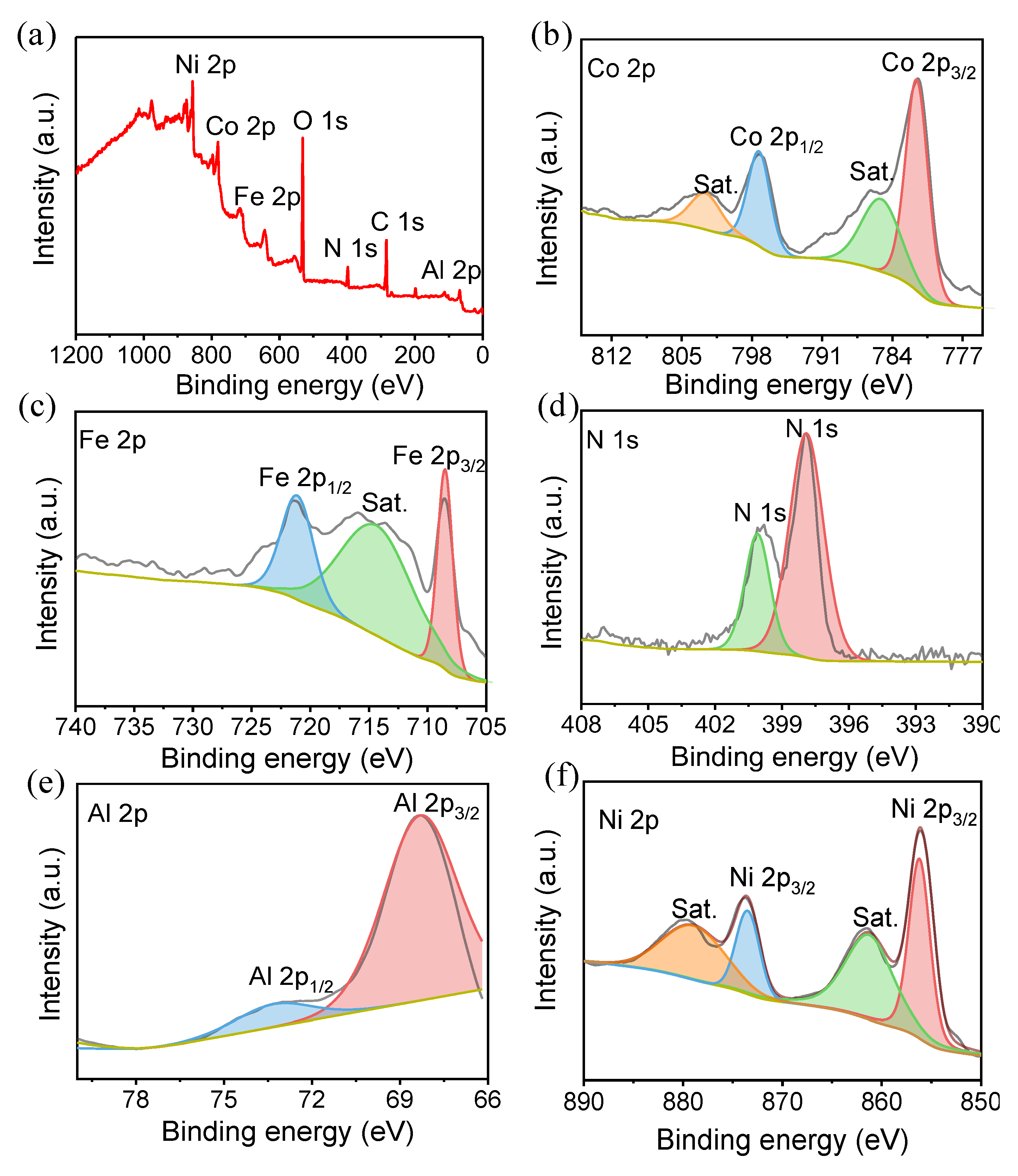
The surface chemical composition and valence state of the Al-Co2Fe(CN)6/NF were monitored by X-ray photoelectron spectroscopy (XPS). As shown in Figure 2a, the XPS survey spectra showed that Co, Fe, N, Al and Ni elements exist on the catalyst surface. In the Co 2p spectrum (Figure 2b), two main peaks were found at 781.1 eV and 797.1 eV, corresponding to Co 2p3/2 and Co 2p1/2 of cobalt hydroxide [30]. As shown in Figure 2c, two main peaks at 708.5 eV and 721.1 eV in the Fe 2p spectrum, corresponding to characteristic bonds of Fe 2p3/2 and Fe 2p1/2 of iron hydroxide. Figure 2d showed that the N 1s XPS spectrum were concentrated at 398.5 eV and 400.0 eV, indicating the presence of pyridine-N and pyrrole-N in the Al-Co2Fe(CN)6. In Figure 2e, binding energies at 73.54 eV and 67.48 eV in Al 2p spectrum accompanied by satellite peaks were observed, which belonged to the Al 2p1/2 and Al 2p3/2 orbits, respectively. The high-resolution Ni 2p spectrum in Figure 2f have two peaks at 871.97 eV and 854 eV, corresponding to Ni 2p3/2 and Ni 2p1/2, respectively, indicating the presence of nickel hydroxide [31] .

2.2. Electrochemical catalytic performances

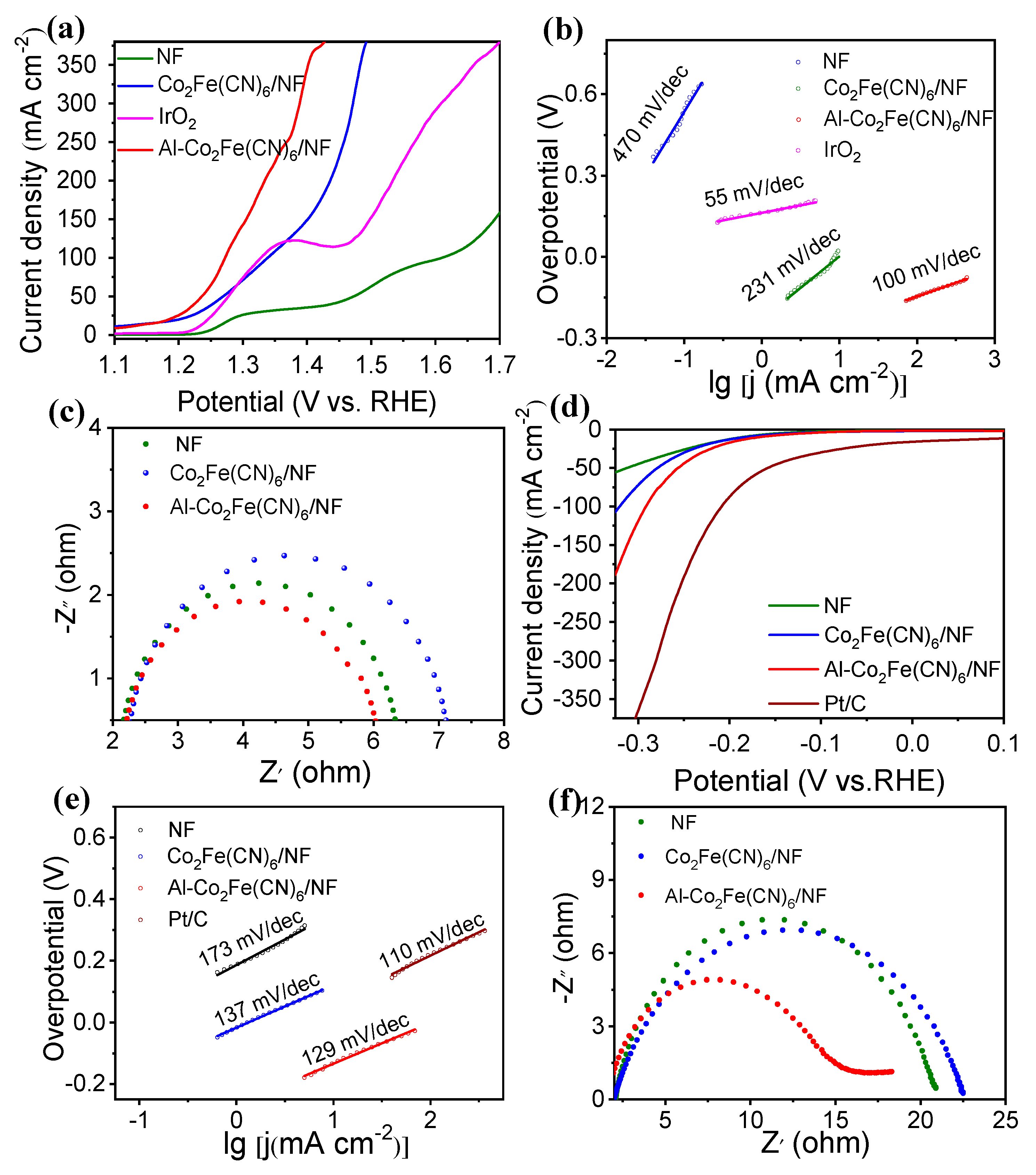
The electrocatalytic activity to UOR was performed in 1.0 M potassium hydroxide aqueous solution containing 0.5 M Urea. The synthetic parameters for the Al-Co2Fe(CN)6/NF were optimized according to their catalytic performance by controlling the reaction times, Co2+ and Al3+ concentration, the type of doped elements. Figure S3 and S4 showed that the Al-Co2Fe(CN)6/NF exhibited best catalytic property to UOR under the optimal synthetic conditions at: 24 h of reaction time, concentration of Co2+ and Al3+ at 0.75 M and 1 mM, respectively, and the aluminum doping. As shown in Figure S5, the Al-Co2Fe(CN)6/NF composite exhibited highest current response in the 1.0 M KOH electrolyte solution consisting of 0.5 M Urea. So, the catalytic performance of the catalysts was performed in 1.0 M KOH electrolyte solution consisting of 0.5 M urea. Linear scanning voltammetry (LSV) curves of the Al-Co2Fe(CN)6/NF, Co2Fe(CN)6/NF and NF were shown in Figure 3. The Al-Co2Fe(CN)6/NF shows high activity to UOR, which only needs a potential of 1.272 V (vs. RHE) at a current density of 100 mA, much smaller than that of NF (1.61 V vs. RHE) and Co2Fe(CN)6/NF (1.339 V vs. RHE). Moreover, the potential of UOR for Al-Co2Fe(CN)6/NF is obviously lower than that to OER (1.440 V vs. RHE), resulting in energy saving for hyrogen production. The UOR activity for Al-Co2Fe(CN)6/NF was comparable to other similar electrocatalysts in Table S1 (Supplementary Information). The results demonstrated the Al-Co2Fe(CN)6/NF possess a satisfactory catalytic performance to UOR.
The Tafel slope values were obtained to study the reaction kinetics according to the LSV curves. As shown in Figure 3b, the Tafel slopes of Al-Co2Fe(CN)6/NF, Co2Fe(CN)6/NF, NF and IrO2 to UOR are 100 mV/dec, 231 mV/dec, 470 mV/dec and 55 mV/dec, respectively. Among these, Al-Co2Fe(CN)6/NF has a smallest Tafel slope value, suggesting a fast electron transport in the electrochemical urea oxidation process. The excellent kinetic property of the Al-Co2Fe (CN)6/N during the UOR process was further reflected by the electrochemical impedance (EIS) test in 1.0 M KOH with 0.5 M Urea. As shown in Figure 3c, the charge transfer resistance of Al-Co2Fe(CN)6/NF is 6.03 Ω, which is obviously lower than those of Co2Fe(CN)6/NF (6.39 Ω) and NF (7.18 Ω). This result proved that Al-Co2Fe(CN)6/NF had higher conductivity and faster electron transfer characteristics, which can greatly promoted the UOR performance.
In order to prove the superiority of the material’s catalytic activity, the HER catalytic activity of Al-Co2Fe(CN)6/NF, Co2Fe(CN)6/NF, NF, and the commercial Pt/C were also explored in the Ar-saturated 1.0 m KOH electrolyte. As shown in Figure 3d, the Al-Co2Fe(CN)6/NF demonstrated an overpotential of 169 mV (vs. RHE) at a current density of 10 mA/cm2, which is clearly lower than those of NF (188 mV vs. RHE) and Co2Fe(CN)6/NF (184 mV vs.RHE), confirming the enhanced activity of Al-Co2Fe (CN)6/NF. However, the HER activity of Al-Co2Fe(CN)6/NF is still poor than that of commercial Pt/C. The polarization curves of the Al-Co2Fe(CN)6/NF to HER in different electrolyte solutions of 1.0 M KOH, 1.0 M KOH with 0.33 M Urea, and 1.0 M KOH with 0.5 M Urea are present in Figure S5b. The HER activity of Al-Co2Fe(CN)6/NF are essentially identical in 1.0 M KOH and 1.0 M KOH with 0.5 M Urea. This results confirmed the urea has negligible electrolyte effects on the HER activity of Al-Co2Fe(CN)6/NF.
To further analyze the kinetics of the catalysts to HER, the Tafel slopes were demonstrated in Figure 3e. The Tafel slopes of Al-Co2Fe(CN)6/NF, Co2Fe(CN)6/NF, NF, and Pt/C for HER are 129 mV/dec, 137 mV/dec, 137 mV/dec, 173 mV/dec and 110 mV/dec, respectively. In contrast to Co2Fe(CN)6/NF and NF, Al-Co2Fe (CN)6/NF has a smallest value of Tafel slope. This verified the facilitated HER kinetics of Al-Co2Fe (CN)6/NF, and was consistent with the Volmer-Heyrovsky mechanism in alkaline electrolyte. The electron transfer kinetics during the HER process can be reflected by the EIS of the Al-Co2Fe(CN)6/NF in 1.0 M KOH with 0.5 M Urea. According to the Figure 3f, the charge transfer resistance of Al-Co2Fe(CN)6/NF (15.01 Ω) is smaller than those of Co2Fe(CN)6/NF (21.05 Ω) and NF (22.60 Ω). This result indicates that Al Co2Fe (CN) 6/NF has a fast electron transfer rate and high conductivity, which contributed greatly to the HER activity. The electric double-layer capacitance (Cdl) reflects the value of electrochemical active surface area (ECSA). The CVs of Al-Co2Fe(CN)6/NF, Co2Fe(CN)6/NF and NF in 1.0 M KOH with 0.5 M Urea at 10-110 mV/s sweep were shown in Figure S6a-c, respectively. Linear fitting diagrams of the current density difference (Δj) and the sweep speed were obtained for Al-Co2Fe(CN)6/NF, Co2Fe(CN)6/NF, and NF, as shown in Figure S6d. The capacitance value (Cdl) of Al-Co2Fe(CN)6/NF (6.255 mF/cm2) is larger that of Co2Fe(CN)6/NF (2.745 mF/cm2) and NF electrode (0.695 mF/cm2). This result indicated that the Al-Co2Fe(CN)6/NF had a high ECSA, which may offer more active sites for HER.

2.3. Whole urea electrolysis

Considering the good electrocatalytic performance of Al-Co2Fe(CN)6/NF electrode to both HER and UOR, a whole urea electrolysis system was developed using Al-Co2Fe(CN)6/NF as anode and cathode, respectively. Figure 4a illustrated the coupling HER||UOR system. Figure 4b is the optical image of HER||OER system and HER||UOR system for hydrogen generation. The generated bubbles are more obvious in HER||UOR system than those in HER||OER system, indicating that the catalyst has a better catalytic performance for the UOR. From the polarization curve in Figure 4c, the current density of HER||OER system with Al-Co2Fe(CN)6/NF as electrode reached 10 mA cm–2 at a cell voltage of 1.52 V. However, the HER||UOR system only needed a cell voltage of 1.36 V to achieve a current density of 10 mA cm–2, as shown in Figure 4d, which is much smaller than the traditional water electrolysis system. At the same time, under the cell voltage of 1.49 V (corresponding to the current density of 50 mA cm–2), compared with the water electrolysis system, the current density of the water-urea system is increased by about 6.35 times. This proves that replacing OER with UOR is an energy-saving strategy for hydrogen production. In addition, in the same HER||UOR coupling system, the overall electrocatalytic performance of Al-Co2Fe(CN)6/NF is even better than that of noble metal-based catalyst, that is, at a current density of 50 mA cm–2, the battery voltage is 1.492 V, while the Pt/C‖RuO2 is 1.542 V.

2.4. Stability of the catalyst

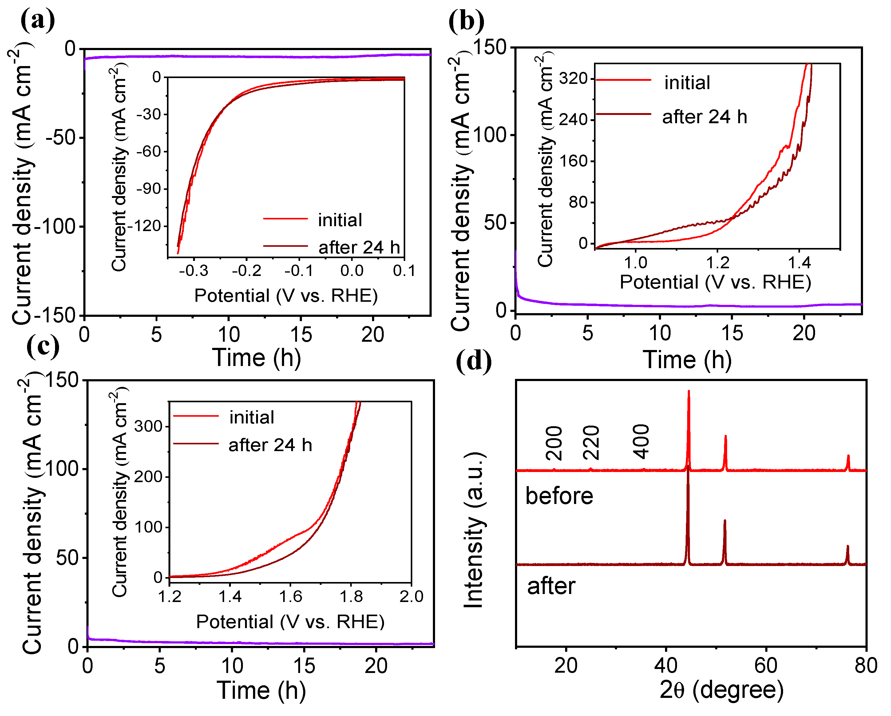
Under the current density of 10 mA cm-2, the stability of Al-Co2Fe(CN)6/NF to HER, UOR and whole urea electrolysis were tested respectively, as shown in Figure 5. From Figure 5a, the current density kept steadily for continuous 24 h electrolysis. The polarization curves also did not changed before and after 24 h electrolysis, suggesting the high HER stability of Al-Co2Fe(CN)6/NF. It can be seen from Figure 5b, the Al-Co2Fe(CN)6/NF also have a good stability for UOR. As shown in Figure 5c, the current density decreased slightly but tended to be stable. The LSV was basically the same before and after the reaction, which proved that the Al-Co2Fe(CN)6/NF assembled into an HER||UOR cell still had good stability. According to the XRD pattern in Figure 5d, there is no obvious change for Al-Co2Fe(CN)6/NF before and after urea electrolysis, indicating that the Al-Co2Fe(CN)6/NF possess a stable chemical structure.
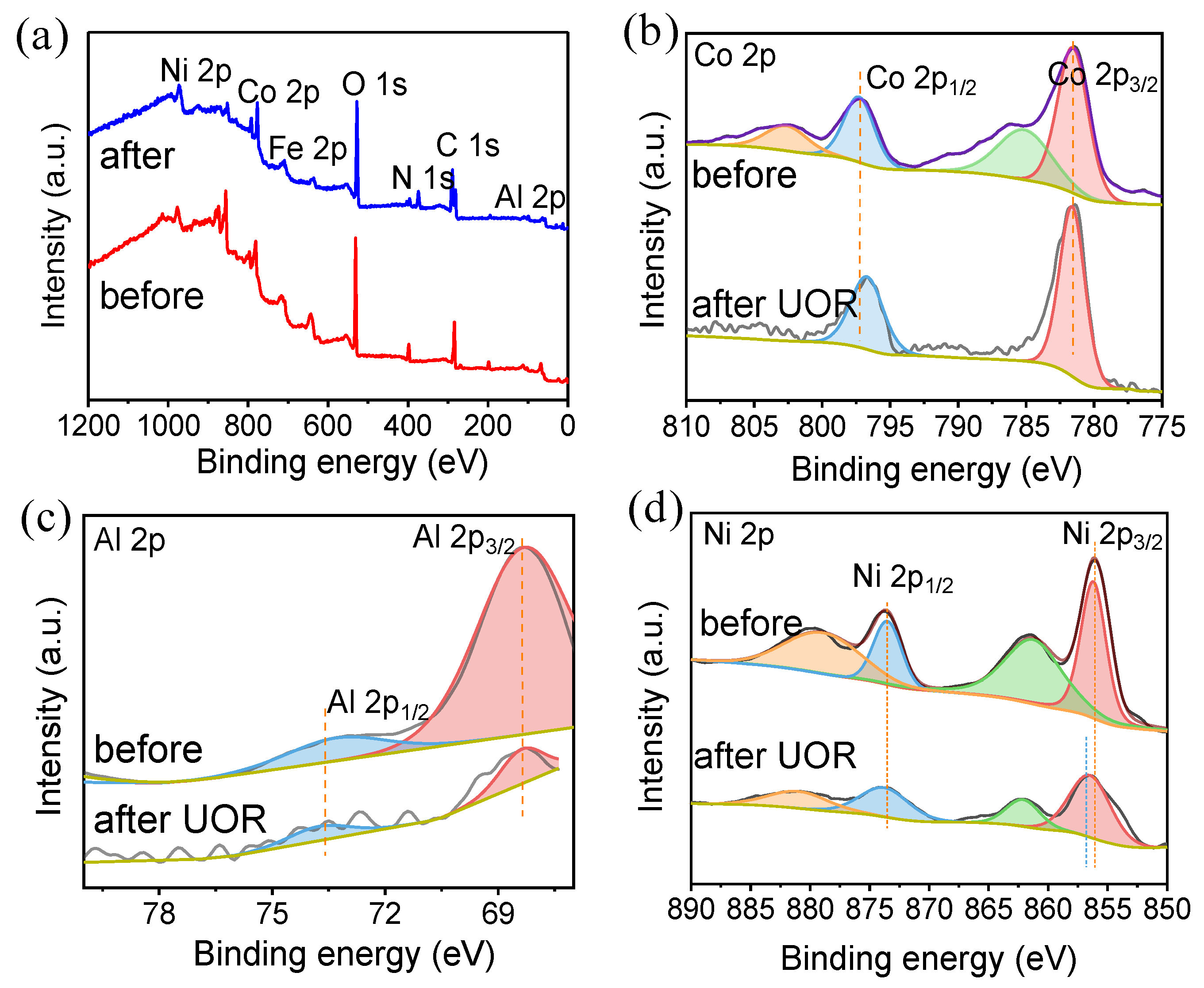
Figure 6a is an XPS spectra of Al-Co2Fe(CN)6/NF before and after 24-hour electrolysis, as shown in the figure, by observing the full spectrum of XPS, Al-Co2Fe(CN)6/NF is mainly composed of Co, Fe, C, N and Al, which is consistent with the result of element mapping, and the peak of Ni is generated by NF substrate. As shown in Figure 6b-d, the peaks before and after the reaction hardly changed, and during the 24 h UOR electrolysis, CoOOH, FeOOH and NiOOH peaks were not observed, indicating that Co2+, Fe2+ and Ni2+ were not oxidized during the catalytic process, which is different from the mechanism of other nickel-based catalysts reported. [32,33] .

2.5. Catalytic Mechanisms

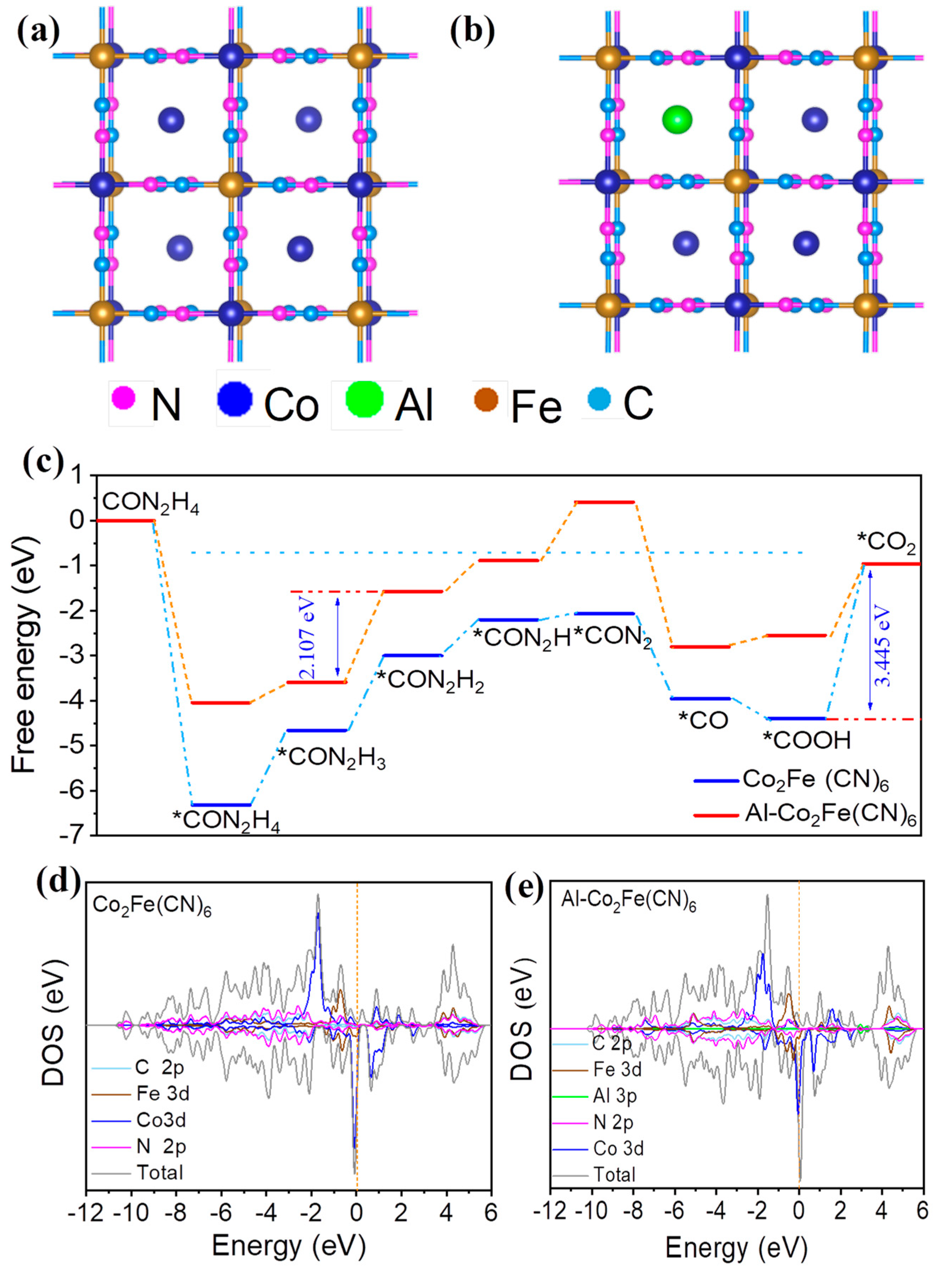
The UOR process has a 6e transfer reaction, which establishes a mature reaction mechanism and mature proportional relationship for each reaction intermediate. It has been reported many substitution mechanisms on the surface of NiOOH [34]. This has been extensively validated in other multi-electron transfer reactions. The schematic diagram of Co2Fe(CN)6 is shown in Figure 7a, the whole structure is a square structure composed of four small units, which is regularly distributed. The doping of Al may replace the position of partial Co2+, so it is speculated that the structural diagram of Al-Co2Fe(CN)6 should be shown in Figure 7b. In this structure, the Fe atom is at the various vertices of the quartet, and the Co atom is at the center of the scaffold, and this stable structure gives it better UOR performance.
In order to further explore the reason why catalysts improve the activity of UOR, density functional theory (DFT) calculation was carried out to reveal the potential catalytic mechanism. The typical UOR reaction path is:
* C O ( N H 2 ) 2 * C O ( N H · N H 2 ) * C O ( N H N H ) * C O ( N H · N ) * C O ( N 2 ) * C O ( O H ) * C O ( O H · O H ) * C O O
where attachment of *COO intermediate is the rate determination step [35,36]. In this catalytic reaction, the decisive step (RDS) of the whole reaction is that the intermediate *CON2H3 desorbs from the active site to form *CON2H2.
As can be seen from Figure 7c, the rate determination step (RDS) of the whole reaction without Al doping is the beginning of the *COOH form *CO2 fast step, and the calculated ∆G is 3.445 eV. For Al-Co2Fe(CN)6, the required ∆G is significantly reduced to 2.107 eV, and the required energy is significantly reduced. Therefore, the electrocatalytic activity of aluminum-doped electrocatalysts is better than that of catalysts without aluminum. When Co2Fe(CN)6 is doped with Al, the energy changes and the overpotential decreases. The experimental and theoretical results show that Al doping is indeed beneficial to the catalytic reaction of UOR.
By calculating the DOS (Density of states) of the catalyst, we further explain the potential reasons for the improvement of the catalyst performance. As shown in Figure 7e and d, because the electronic state near the Fermi level is mainly provided by the d orbit of Co atoms, and the DOS of the d orbit after doping Al atoms is significant near the Fermi level. The DOS of d orbit is shifted up and closer to the Fermi level. Therefore, the electronic state is more active, which is conducive to the adsorption of catalyst and intermediate and promotes the reaction.

3. Experimental

3.1. Materials and chemicals

Ni foam was commercial from Tianjin aiweixin Chemical Technology Co., Ltd; CoCl2·6H2O (analytical reagent, AR) and Al(NO3)3 (AR) were purchased from Sinopharm Chemical Reagent. CH3CH2OH, KOH(AR), urea (AR), C6H5Na3O7·2H2O (AR), K3[Fe(CN)6] (AR) were from Tianjin Damao chemical reagent factory. Polyvinylpyrrolidone (PVP) was purchased from Macklin. Nafion (5wt%) was purchased from The United States DuPont; Pt/C and IrO2 were from Aladdin.

3.2. Preparation of the Al-Co2Fe(CN)6/NF electrode

The nickel foam was first cut into 4 cm×4 cm pieces, and washed with acetone, ethanol, deionized water for 30 min, and then dried for future use. 0.5000 g of PVP, 0.1784 g of CoCl2·6H2O, 0.3088 g of C6H5Na3O7·2H2O, 0.0375 g of Al(NO3)3 were added in 150 mL deionized water, stirring at room temperature to form aqueous solution A. Then, put a nickel foam into solution A. 0.0823 g of K3[Fe(CN)6] was dissolved in 100 mL deionized water to form aqueous solution B. Subsequently, mixed the solution A and B, and added solution B, and seal up and stir for 24h. Finally, the Al-Co2Fe(CN)6/NF was washed thoroughly with deionized water and dried overnight. The Co2Fe(CN)6/NF was obtained as the above same procedures without add Al(NO3)3.

3.3. Electrochemical measurements

The electrochemical performance of the UOR and HER was tested in a three-electrode system on an electrochemical workstation (CHI 920D). As-prepared Al-Co2Fe(CN)6/NF was used as working electrode, a saturated calomel electrode (SCE) as reference electrode and a graphite rod as counter-electrode. All potentials reported in this work reference the reversible hydrogen electrode (RHE) according to E (vs.RHE)=E(vs.SCE)+0.0591×pH+0.242. Hydrogen overpotential and oxygen overpotential are calculated by formula η = 0 E v s . R H E η = E v s . R H E 1.23 V calculation, respectively.
The cyclic voltammogram (CV) were recorded at scan rates of 10−110 mV s−1. The LSV curve was recorded at a scan rate of 5 mV s−1. The iR compensation level is 100%. Electrochemical impedance spectroscopy (EIS) tests were measured over a frequency range from 105 to 10-2 Hz with an amplitude of 5 mV. The electrochemical double capacitance (Cdl) is calculated from the CV curve at different sweep speeds (10-110 mV s−1). The i-t curves were obtained to test the stability.

3.4. DFT

The VASP mode was employed to the DFT calculations [37]. Exchange and correlation potentials was modeled by selecting the GGA-PBE function [38]. The DFT-D3 functional also considers weak van der Waals interactions [39]. The cutoff energy value of plane waves was 400 eV. We selected gamma points in the Brillouin zone for integration. In the iterative solution of the Kohn Sham equation, the total energy of the system converged to 10-5 eV. After geometric optimization, the force on each atom was reduced to 0.05 eV/Å.

4. Conclusion

In conclusion, Al-Co2Fe(CN)6 nanocube array is grown in situ on nickel foam (Al-Co2Fe(CN)6/NF) by one step in-situ growth. Due to the unique nanocube array structure and regular electronic structure of Al-Co2Fe(CN)6, the prepared Al-Co2Fe(CN)6/NF catalyst showed excellent catalytic activity and long-term stability for HER and UOR. During the electrolysis process, the chemical structure and valence state of Co in Al-Co2Fe(CN)6 catalysis is not turned into Co hydroxide derivatives. Combination of experiments and DFT calculation, a more favorable UOR pathway at Al-Co2Fe(CN)6/NF is proposed. The DFT results show that the doping of Al can optimize the electronic structure, thus improving the adsorption, and significantly enhancing the catalytic activity to UOR. Al-Co2Fe(CN)6/NF was used as the cathode and anode, and an energy-saving two-electrode system for hydrogen generation was constructed. The Al-Co2Fe(CN)6/NF requires less electric power and reduces the urea content of wastewater. Consequently, this work will open a way for the development of sustainable energy conversion by combining hydrogen production with urea wastewater treatment.

Supplementary Materials

The following supporting information can be downloaded at the website of this paper posted on Preprints.org.

Author Contributions

Conceptualization, J.P.; methodology, X.G. and M.G.; formal analysis, M.G., X.J. and X.Y.; investigation, X.G. and M.G.; resources, J.P.; data curation, X.G. and M.G.; writing -original draft preparation, X.G., X.Y. and J.P.; writing-review and editing, J.P.; visualization, X.J. and G.N.; project administration, J.P.; funding acquisition, G.N, J.P. All authors have read and agreed to the published version of the manuscript.

Funding

This work was funded by the support from the National Natural Science Foundation of China (No. 22262027).

Institutional Review Board Statement

Not applicable.

Informed Consent Statement

Not applicable.

Data Availability Statement

All data in this study can be found in public data bases and Supplementary Information, as described in the Material and Methods section (Section 3).

Conflicts of Interest

The authors declared no competing financial interest.

References

  1. Zhang, P.; Li, L.; Nordlund, D.; Chen, H.; Fan, L.; Zhang, B.; Sheng, X.; Daniel, Q.; Sun, L. Dendritic core-shell nickel-iron-copper metal/metal oxide electrode for efficient electrocatalytic water oxidation. Nat. Commun. 2018, 9, 381. [Google Scholar] [CrossRef]
  2. Krausfeldt, L.E.; Farmer, A.T.; Gonzalez, H.F.C.; Zepernick, B.N.; Campagna, S.R.; Wilhelm, S.W. Urea Is Both a Carbon and Nitrogen Source for Microcystis aeruginosa: Tracking 13C Incorporation at Bloom pH Conditions. Front. Microbiol. 2019, 10, 1064. [Google Scholar] [CrossRef]
  3. Rollinson, A.N.; Jones, J.; Dupont, V.; Twigg, M.V. Urea as a hydrogencarrier: a perspective on its potential for safe, sustainable and long-term energy supply. Energy Environ. Sci. 2011, 4, 1216–1224. [Google Scholar]
  4. Wang, G.; Ling, Y.; Lu, X.; Wang, H.; Qian, F.; Tong, Y.; Li, Y. Solar driven hydrogen releasing from urea and human urine. Energy Environ. Sci. 2012, 5, 8215–8219. [Google Scholar] [CrossRef]
  5. Wei, S.; Wang, X.; Wang, J.; Sun, X.; Cui, L.; Yang, W.; Zheng, Y.; Liu, J. CoS2 nanoneedle array on Ti mesh: A stable and efficient bifunctional electrocatalyst for urea-assisted electrolytic hydrogen production. Electrochimica Acta 2017, 246, 776–782. [Google Scholar] [CrossRef]
  6. Boggs, B.K.; King, R.L.; Botte, G.G. Urea electrolysis: direct hydrogen production from urine. Chem. Commun. 2009, 4859–4861. [Google Scholar] [CrossRef] [PubMed]
  7. Yan, W.; Wang, D.; Botte, G.G. Template-assisted synthesis of Ni–Co bimetallic nanowires for urea electrocatalytic oxidation. J. Appl. Electrochem. 2015, 45, 1217–1222. [Google Scholar] [CrossRef]
  8. Simka, W.; Piotrowski, J.; Robak, A.; Nawrat, G. Electrochemical treatment of aqueous solutions containing urea. J. Appl. Electrochem. 2009, 39, 1137–1143. [Google Scholar] [CrossRef]
  9. King, R.L.; Botte, G.G. Investigation of multi-metal catalysts for stable hydrogen production via urea electrolysis. J. Power Sources 2011, 196, 9579–9584. [Google Scholar] [CrossRef]
  10. Barbosa, J.R.; Paranhos, C.H.; Alves, O.C.; Checca, N.R.; Serna, J.P.; Rossi, A.L.; Silva, J.C.M. Low loading platinum dispersed on Ni/C nanoparticles as high active catalysts for urea electrooxidation reaction. Electrochimica Acta 2020, 355, 136752. [Google Scholar] [CrossRef]
  11. Yan, D.; Xia, C.; Zhang, W.; Hu, Q.; He, C.; Xia, B.Y.; Wang, S. Cation Defect Engineering of Transition Metal Electrocatalysts for Oxygen Evolution Reaction. Adv. Energy Mater. 2022, 12, 2202317. [Google Scholar] [CrossRef]
  12. Zhao, R.; Li, Q.; Jiang, X.; Huang, S.; Fu, G.; Lee, J.-M. Interface engineering in transition metal-based heterostructures for oxygen electrocatalysis. Mater. Chem. Front. 2021, 5, 1033–1059. [Google Scholar] [CrossRef]
  13. Zhang, J.-Y.; He, T.; Wang, M.; Qi, R.; Yan, Y.; Dong, Z.; Liu, H.; Wang, H.; Xia, B.Y. Energy-saving hydrogen production coupling urea oxidation over a bifunctional nickel-molybdenum nanotube array. Nano Energy 2019, 60, 894–902. [Google Scholar] [CrossRef]
  14. Zhu, B.; Liang, Z.; Zou, R. Designing Advanced Catalysts for Energy Conversion Based on Urea Oxidation Reaction. Small 2020, 16, 1906133. [Google Scholar] [CrossRef]
  15. Ding, Y.; Li, Y.; Xue, Y.; Miao, B.; Li, S.; Jiang, Y.; Liu, X.; Chen, Y. Atomically thick Ni(OH)2 nanomeshes for urea electrooxidation. Nanoscale 2019, 11, 1058–1064. [Google Scholar] [CrossRef]
  16. Qin, H.; Ye, Y.; Li, J.; Jia, W.; Zheng, S.; Cao, X.; Lin, G.; Jiao, L. Synergistic Engineering of Doping and Vacancy in Ni(OH)2 to Boost Urea Electrooxidation. Adv. Funct. Mater. 2022, 33, 2209698. [Google Scholar] [CrossRef]
  17. Zhu, Y.; Liu, C.; Cui, S.; Lu, Z.; Ye, J.; Wen, Y.; Shi, W.; Huang, X.; Xue, L.; Bian, J.; et al. Multistep Dissolution of Lamellar Crystals Generates Superthin Amorphous Ni(OH)2 Catalyst for UOR. Adv. Mater. 2023, 35, e2301549. [Google Scholar] [CrossRef]
  18. Wang, J.; Zhao, Z.; Shen, C.; Liu, H.; Pang, X.; Gao, M.; Mu, J.; Cao, F.; Li, G. Ni/NiO heterostructures encapsulated in oxygen-doped graphene as multifunctional electrocatalysts for the HER, UOR and HMF oxidation reaction. Catal. Sci. Technol. 2021, 11, 2480–2490. [Google Scholar] [CrossRef]
  19. Zhao, Q.; Meng, C.; Kong, D.; Wang, Y.; Hu, H.; Chen, X.; Han, Y.; Chen, X.; Zhou, Y.; Lin, M.; et al. In Situ Construction of Nickel Sulfide Nano-Heterostructures for Highly Efficient Overall Urea Electrolysis. ACS Sustain. Chem. Eng. 2021, 9, 15582–15590. [Google Scholar] [CrossRef]
  20. Zhang, Y.; Guo, H.; Song, M.; Sun, L.; Song, R. Modulation of the morphology and electronic structure of Ni3S2 nano-forests via P and Mo co-doping in polyoxometalates to promote the urea oxidation reaction. J. Mater. Chem. A 2023, 11, 3584–3593. [Google Scholar] [CrossRef]
  21. Jia, X.; Kang, H.; Yang, X.; Li, Y.; Cui, K.; Wu, X.; Qin, W.; Wu, G. ,Jia, X.; Kang, H.; Yang, X.; Li, Y.; Cui, K.; Wu, X.; Qin, W.; Wu, G. Amorphous Ni(Ⅲ)-based sulfides as bifunctional water and urea oxidation anode electrocatalysts for hydrogen generation from urea-containing water. Appl. Catal. B Environ. 2022, 312, 121389. [Google Scholar] [CrossRef]
  22. Yuan, W.; Jiang, T.; Fang, X.; Fan, Y.; Qian, S.; Gao, Y.; Cheng, N.; Xue, H.; Tian, J. Interface engineering of S-doped Co2P@Ni2P core–shell heterostructures for efficient and energy-saving water splitting. Chem. Eng. J. 2022, 439, 135743. [Google Scholar] [CrossRef]
  23. Jiang, H.; Sun, M.; Wu, S.; Huang, B.; Lee, C.; Zhang, W. Oxygen-Incorporated NiMoP Nanotube Arrays as Efficient Bifunctional Electrocatalysts For Urea-Assisted Energy-Saving Hydrogen Production in Alkaline Electrolyte. Adv. Funct. Mater. 2021, 31, 2104951. [Google Scholar] [CrossRef]
  24. Tesfaye, R.M.; Das, G.; Park, B.J.; Kim, J.; Yoon, H.H. Ni-Co bimetal decorated carbon nanotube aerogel as an efficient anode catalyst in urea fuel cells. Sci. Rep. 2019, 9, 479. [Google Scholar] [CrossRef]
  25. Li, J.; Cui, H.; Du, X.; Zhang, X. The controlled synthesis of nitrogen and iron co-doped Ni3S2@NiP2 heterostructures for the oxygen evolution reaction and urea oxidation reaction. Dalton Trans. 2022, 51, 2444–2451. [Google Scholar] [CrossRef]
  26. Shen, J.; Li, Q.; Zhang, W.; Cai, Z.; Cui, L.; Liu, X.; Liu, J. Spherical Co3S4 grown directly on Ni–Fe sulfides as a porous nanoplate array on FeNi3 foam: a highly efficient and durable bifunctional catalyst for overall water splitting. J. Mater. Chem. A. 2022, 10, 5442–5451. [Google Scholar] [CrossRef]
  27. Yang, X.; Zhang, H.; Yu, B.; Liu, Y.; Xu, W.; Wu, Z. An Unveiled Electrocatalysis Essence of NiCo Hydroxides through in Situ Raman Spectroscopy for Urea Oxidation. Energy Technol-GER. 2022, 10, 2101010. [Google Scholar] [CrossRef]
  28. Xu, Y.; Ren, T.; Ren, K.; Yu, S.; Liu, M.; Wang, Z.; Li, X.; Wang, L.; Wang, H. Metal-organic frameworks-derived Ru-doped Co2P/N-doped carbon composite nanosheet arrays as bifunctional electrocatalysts for hydrogen evolution and urea oxidation. Chem. Eng. J. 2021, 408, 127308. [Google Scholar] [CrossRef]
  29. Chen, F.; Yang, F.; Sheng, C.; Li, J.; Xu, H.; Qing, Y.; Chen, S.; Wu, Y.; Lu, X. Electronic structure modulation of nickel hydroxide porous nanowire arrays via manganese doping for urea-assisted energy-efficient hydrogen generation. J. Colloid Interface Sci. 2022, 626, 445–452. [Google Scholar] [CrossRef]
  30. Zhou, T.; Cao, Z.; Wang, H.; Gao, Z.; Li, L.; Ma, H.; Zhao, Y. Ultrathin Co–Fe hydroxide nanosheet arrays for improved oxygen evolution during water splitting. RSC Adv. 2017, 7, 22818–22824. [Google Scholar] [CrossRef]
  31. Man, I.C.; Su, H.-Y.; Calle-Vallejo, F.; Hansen, H.A.; Martínez, J.I.; Inoglu, N.G.; Kitchin, J.; Jaramillo, T.F.; Nørskov, J.K.; Rossmeisl, J. Universality in Oxygen Evolution Electrocatalysis on Oxide Surfaces. ChemCatChem 2011, 3, 1159–1165. [Google Scholar] [CrossRef]
  32. Sayed, E.T.; Eisa, T.; Mohamed, H.O.; Abdelkareem, M.A.; Allagui, A.; Alawadhi, H.; Chae, K.-J. Direct urea fuel cells: Challenges and opportunities. J. Power Sources 2019, 417, 159–175. [Google Scholar] [CrossRef]
  33. Yao, S.J.; Wolfson, S.K.; Ahn, B.K.; Liu, C.C. Anodic Oxidation of Urea and an Electrochemical Approach to De-ureation. Nature 1973, 241, 471–472. [Google Scholar] [CrossRef] [PubMed]
  34. Kresse, G.; Furthmüller, J.J. Efficient iterative schemes for ab initio total-energy calculations using a plane-wave basis set. Phys Rev B. 1996, 54, 11169. [Google Scholar] [CrossRef] [PubMed]
  35. Perdew, J.P.; Burke, K.; Ernzerhof, M. Generalized gradient approximation made simple. Phys. Rev. Lett. 1996, 77, 3865–3868. [Google Scholar] [CrossRef]
  36. Wang, G.; Ling, Y.; Lu, X.; Wang, H.; Qian, F.; Tong, Y.; Li, Y. Solar driven hydrogen releasing from urea and human urine. Energy Environ. Sci. 2012, 5, 8215–8219. [Google Scholar] [CrossRef]
  37. Min, S.; Zhao, C.; Zhang, Z.; Chen, G.; Qian, X.; Guo, Z.J. Synthesis of Ni(OH)2/RGO pseudocomposite on nickel foam for supercapacitors with superior performance. J. Mater. Chem. A. 2015, 3, 3641–3650. [Google Scholar] [CrossRef]
  38. Zhang, L.; Wang, L.; Lin, H.; Liu, Y.; Ye, J.; Wen, Y.; Chen, A.; Wang, L.; Ni, F.; Zhou, Z.J. A. C. A lattice-oxygen-involved reaction pathway to boost urea oxidation. Nat Energy. 2019, 131, 16976–16981. [Google Scholar]
  39. Daramola, D.A.; Singh, D.; Botte, G.G. Dissociation Rates of Urea in the Presence of NiOOH Catalyst: A DFT Analysis. J. Phys. Chem. A 2010, 114, 11513–11521. [Google Scholar] [CrossRef]
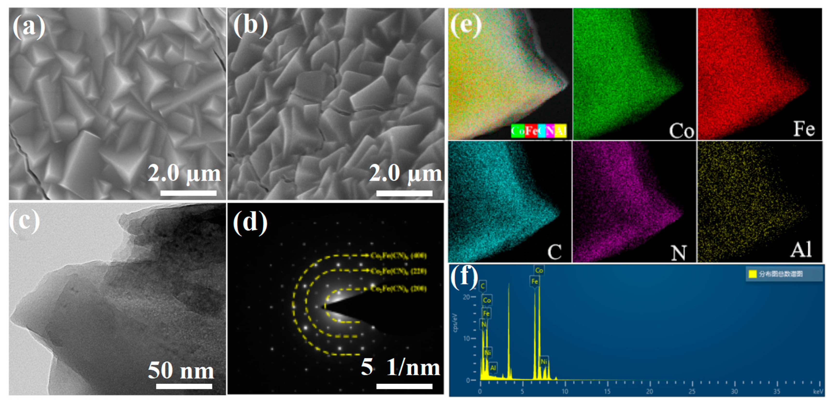
Figure 1. SEM images of (a) Co2Fe(CN)6/NF and (b) Al-Co2Fe(CN)6/NF; (c) TEM and (d) SAED images of Al-Co2Fe(CN)6/NF; (e) HAADF-HRTEM and corresponding elemental mapping images of Al-Co2Fe(CN)6/NF; (f) EDX spectrum of Al-Co2Fe(CN)6/NF.
Preprints 84596 g001
Figure 2. (a) XPS survey spectra of Al-Co2Fe(CN)6/NF; (b) Co 2p spectrum; (c) Fe 2p spectrum; (d) N 1s spectrum; (e) Al 2p spectrum; (f) Ni 2p spectrum.
Preprints 84596 g002
Figure 3. (a) The polarization curves of catalysts in Ar-saturated 1.0 M KOH with 0.5 M Urea; (b) Tafel slope diagram for UOR; (c) EIS; (d) The polarization curves of catalysts in Ar-saturated 1.0 M KOH; (e) Corresponding Tafel slope diagram for HER; (f) EIS diagram.
Preprints 84596 g003
Figure 4. (a) Simulation diagram for HER||UOR system using Al-Co2Fe(CN)6/NF as both cathode and anode; (b) Photograph of HER||OER system, and the electrolyte is 1 M KOH (top); HER||UOR system (down), the electrolyte is 1.0 M KOH with 0.5 M urea; (c) The polarization curves of Pt/C||IrO2 and Al-Co2Fe(CN)6/NF||Al-Co2Fe(CN)6/NF for overall water electrolysis in 1.0 M KOH; (d) The polarization curves of Pt/C||IrO2 and Al-Co2Fe(CN)6/NF||Al-Co2Fe(CN)6/NF for whole urea electrolysis in 1.0 M KOH with 0.5 M Urea.
Preprints 84596 g004
Figure 5. (a) Durability test of Al-Co2Fe(CN)6/NF to HER. The inset shows the polarization curves of Al-Co2Fe(CN)6/NF before and after 24 h electrolysis; (b) UOR durability test of Al-Co2Fe(CN)6/NF. The inset shows the polarization curves of Al-Co2Fe(CN)6/NF before and after the 24 h electrolysis; (c) durability test for whole urea electrolysis using Al-Co2Fe(CN)6/NF || Al-Co2Fe(CN)6/NF.; (d) XRD patterns of Al-Co2Fe(CN)6/NF before and after continuous electrocatalysis for 24 h.
Preprints 84596 g005
Figure 6. (a) XPS survey spectra of Al-Co2Fe(CN)6/NF; (b) Co 2p spectrum; (c) Al 2p spectrum; (d) Ni 2p spectrum before and after 24 h electrolysis.
Preprints 84596 g006
Figure 7. (a) schematic diagram of the structure of Co2Fe(CN)6; (b) schematic diagram of the structure of Al-Co2Fe(CN)6; (c) The Gibbs free energy changes in the UOR process; (d) DOS of the Co2Fe(CN)6; (e) DOS of the Al-Co2Fe(CN)6.
Preprints 84596 g007
Disclaimer/Publisher’s Note: The statements, opinions and data contained in all publications are solely those of the individual author(s) and contributor(s) and not of MDPI and/or the editor(s). MDPI and/or the editor(s) disclaim responsibility for any injury to people or property resulting from any ideas, methods, instructions or products referred to in the content.
Copyright: This open access article is published under a Creative Commons CC BY 4.0 license, which permit the free download, distribution, and reuse, provided that the author and preprint are cited in any reuse.
Prerpints.org logo

Preprints.org is a free preprint server supported by MDPI in Basel, Switzerland.

Subscribe

© 2024 MDPI (Basel, Switzerland) unless otherwise stated