1. Introduction
Automatic transmissions (ATs) with planetary gear trains (PGTs) have long been applied in the automotive industry. The literature on the design of planetary gear trains includes conceptual designs, kinematic analysis, power flow and efficiency analysis, and configuration designs. With an increasing demand for fuel economy and dynamic performance, many companies, such as ZF and Aisin, are developing the planetary gear trains (PGTs) with more gears for vehicles. This is because it allows the engine to work in a high-efficient area to reduce fuel consumption, and the use of suitable transmission ratios can also guarantee abundant torque capacity for strong dynamic performance, thereby, helping to obtain a balance of dynamic and economic performance [
1,
2,
3,
4,
5].
Knowledge of the different types of PGT is of interest both scientifically and technologically. In particular, it could lead to the design and construction of more efficient implementations of such trains. In this regard, PGT efficiency must be understood as a generic and global concept. This is because, given a certain transmission ratio, the designer would like to be able to select from all matching PGTs those that have the right combination of efficiency and simplicity of construction.
One important question is to find an efficient way to select planetary gear trains that allow a high transmission ratio without excessively sacrificing efficiency and without having recourse to great structural complexity. Some study presents a procedure to assess the sensitivity of certain characteristics of a planetary gear train – the efficiency and the transmission ratio – with respect to small variations in the design parameters. The method is only applied to a particular train by way of example rather than by performing an exhaustive analysis of numerous gear trains [
6,
7,
8,
9,
10].
One key point that needs to be taken into account in analyzing and estimating the efficiency of a PGT is its structure. This is determined by the number and type of links, and by the kinematic pairs between them. In particular, the links of PGTs are of three types which in the present work we shall call suns, arms, and planets. The planets are links that undergo a planetary motion. Each planet is linked to its respective arm by a turning pair and to other members by gear pairs. The arms have a rotational movement around the PGT's principal axis, and are characterized by having at least one turning pair with a planet; they may also have gear pairs with other members. Finally, the suns are links that only have gear pairs with other links and also have a rotational movement around the PGT's principal axis. Suns and arms are central links since they rotate around the central axis of the PGT, whereas the planets are non-central links since they have a planetary motion [
11,
12,
13,
14,
15].
For parallel-connected PGTs, Ross and Route introduced an AT design tool based on a lever analogy, which included the calculation of gear ratios, gear trains selection, and the construction of clutch layouts. Nadel et al. formulated the design of ATs as a constraint satisfaction problem which included kinematic, topological, stick diagram, and geometric levels. This methodology was suitable for PGTs in which two simple PGTs were combined. Dong et al. analyzed the relationship between the stationary gear ratios and transmission ratios, and achieved 9, 11 and 13 gears through the same configuration by just changing the stationary gear ratios. Jiang et al. combined different matrices representing different sub-configurations and used kinematic equations to calculate the shaft speeds. Yang et al. proposed a judgement method based on the ranks of structure matrices for three-node compound lever models [
16,
17,
18,
19,
20].
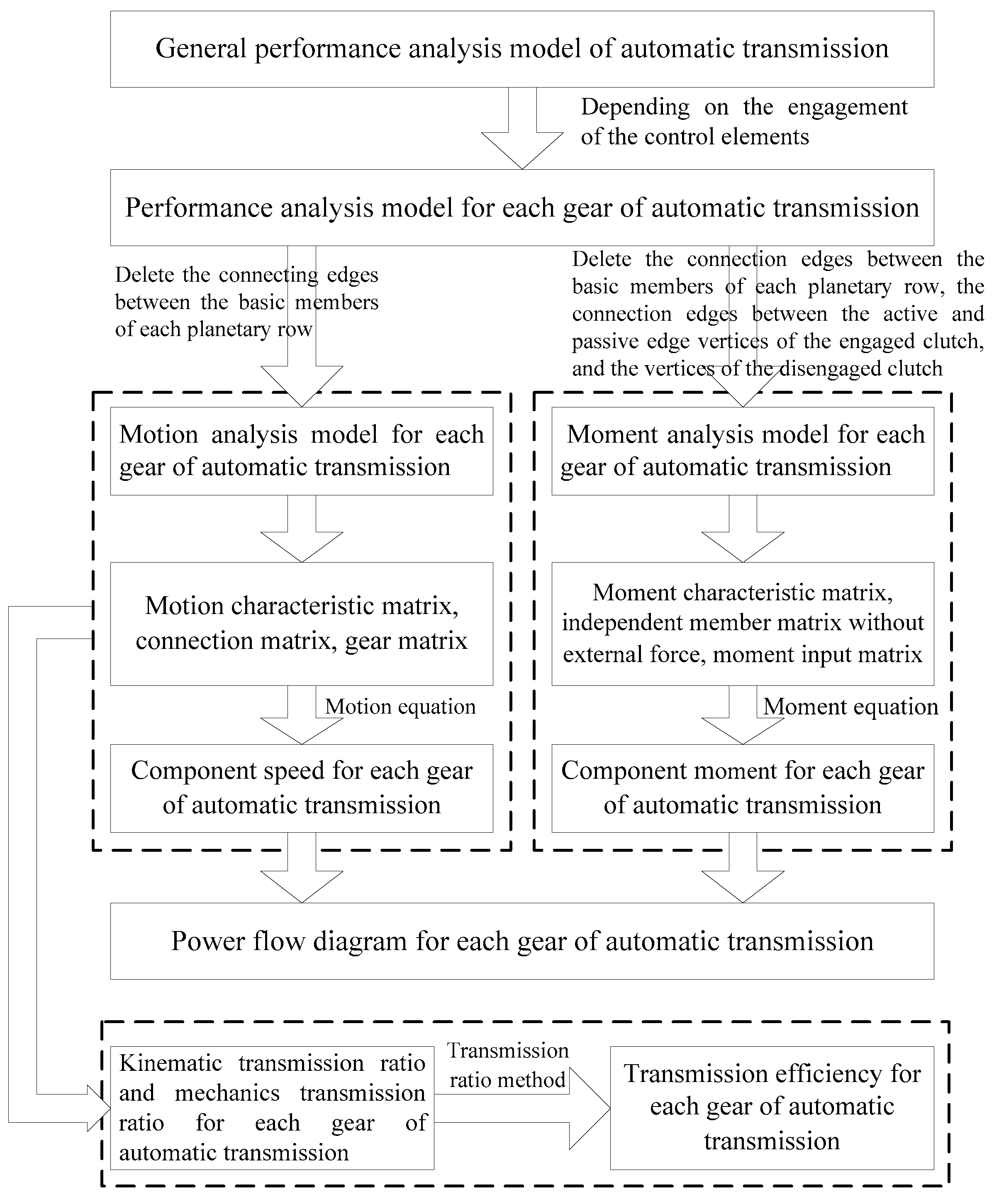
Graph theory provides a new way of thinking for the analysis of systems containing binary relations. Based on the idea of graph theory, the analysis model of planetary gear transmission is established, which provides the possibility of automatic analysis of its transmission performance. This paper will use graph theory to analyze the motion, moment, power flow and efficiency of planetary gear mechanism for automatic transmission, and it is convenient for computer programming. The flow chart of performance analysis for automatic transmission is shown in
Figure 1.
2. Performance Analysis Model of Automatic Transmission
Based on graph theory, dots are used to represent various components of the planetary gear mechanism (including control elements), and lines are used to represent connection relationship between the components [
21,
22,
23,
24,
25,
26,
27,
28,
29,
30].
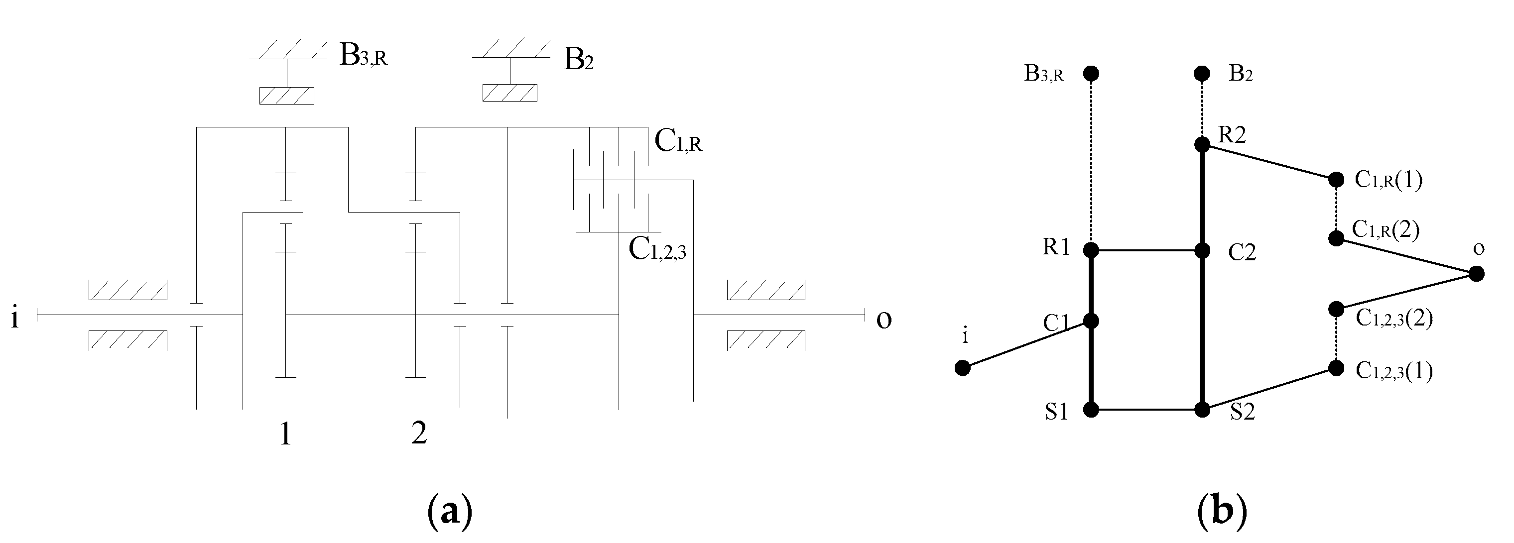
Figure 2(a) is a three-speed planetary gear transmission, and the overall performance analysis model is shown in
Figure 2(b). The dotted edge in
Figure 2(b) indicates that the connection relationship between components is manipulated by control elements.
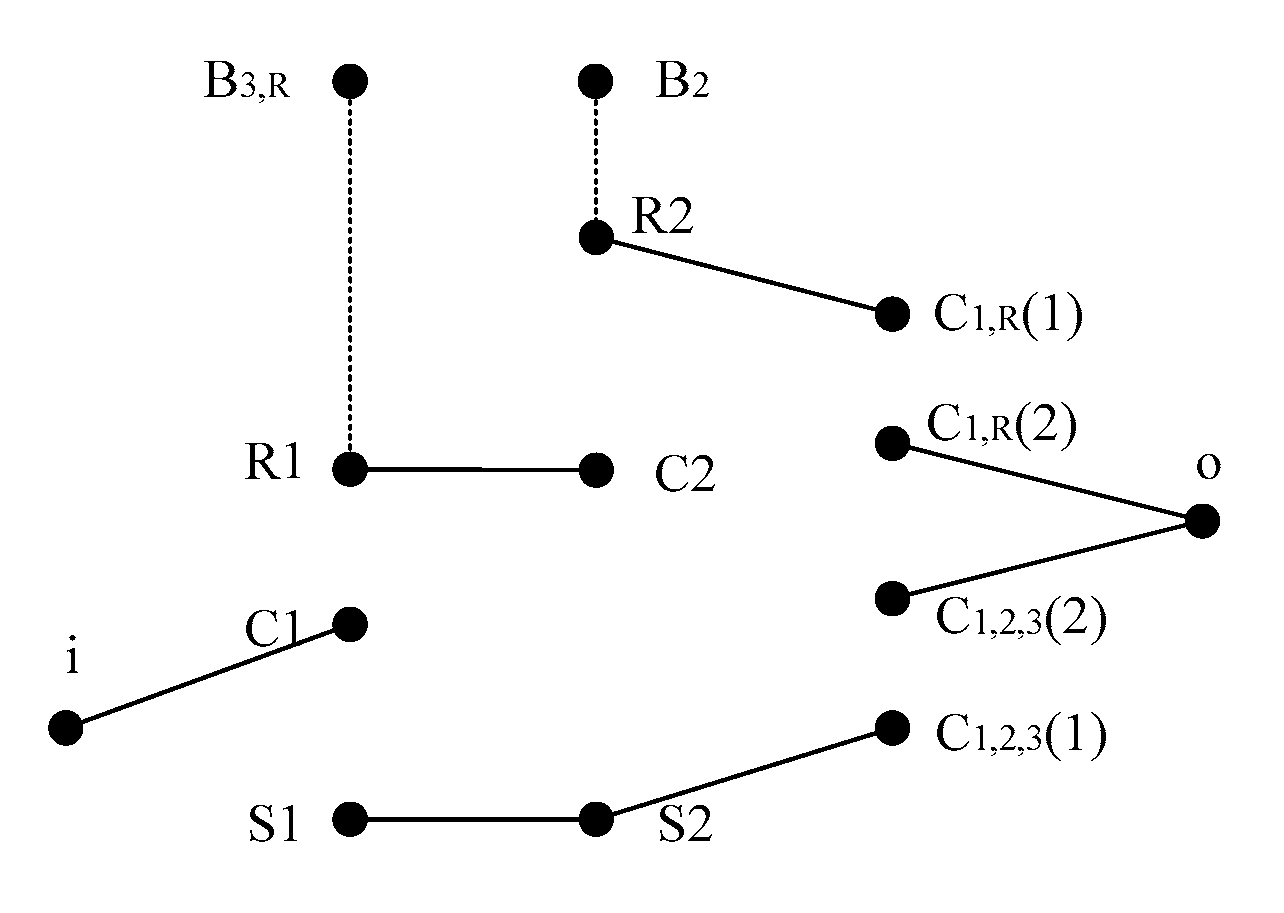
In the overall performance analysis model of planetary gear mechanism, Q connected branches can be obtained by deleting the connecting edges between basic components of each planetary row and the connecting edges between vertices of the active and passive edges of the clutch. The degree of freedom of planetary gear mechanism W=Q-k, where k is the number of planetary rows. From
Figure 2(b), five connected branches can be obtained, as shown in
Figure 3. Therefore, in
Figure 2(a), the degree of freedom of planetary gear transmission W=5-2=3.
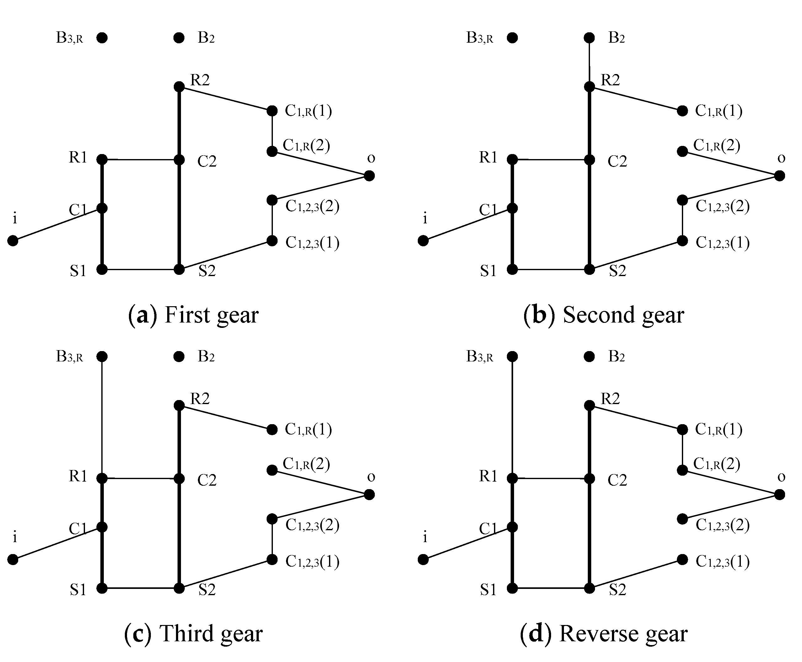
According to the engagement of control elements, on the basis of overall performance analysis model, the analysis model of each gear can be obtained. The state table of control elements for the planetary gear transmission in
Figure 2(a) is shown in
Table 1, and the analysis model of each gear is shown in
Figure 4.
2.1. Motion Analysis of Automatic Transmission
The motion analysis model of each gear of automatic transmission can be obtained by deleting the connection edges between basic components of each planetary row in
Figure 4.
(1) Motion characteristic matrix
The motion characteristic matrix
describes the component motion relationship of each planetary row. The single-star planetary row satisfies motion relationship:
The double-star planetary row satisfies motion relationship:
For a transmission consisting of k single-star planetary rows, its motion characteristic matrix
In the formula, , ,..., are the characteristic parameters of each planetary row, respectively.
(2) Connection matrix
Connection matrix is the matrix describing component connection relationship of each planetary row. If one of the two connected components is marked as 1, the other is marked as -1, and other components are marked as 0, then each two connected components will form a row vector containing only 1, -1, and 0, and the resulting matrix is called connection matrix.
(3) Gear matrix
Gear matrix (i=1,2,3,…) is a matrix representing the brake and clutch engagement state of automatic transmission in each gear. When the brake is engaged, the brake component is marked as 1; when the clutch is engaged, one of the two constant velocity components is marked as 1, the other is marked as -1, and other components are marked as 0. The last line of gear matrix is input vector, and the input component is marked as 1, the others are 0.
For the transmission composed of
k planetary rows, it satisfies the following motion equation:
The speed of each component of automatic transmission and the transmission ratio of each gear can be obtained by solving equation (4).
2.2. Moment Analysis of Automatic Transmission
In
Figure 4, delete the connection edges between basic components of each planetary row,the connection edges between vertices of active and passive edges of the engaged clutches, and the vertices of disengaged clutches, the moment analysis model of each gear of automatic transmission can be obtained.
(1) Moment characteristic matrix
The moment characteristic matrix
describes the component moment relationship of each planetary row. The single-star planetary row satisfies moment relationship:
The double-star planetary row satisfies moment relationship:
For a transmission consisting of k single-star planetary rows, its moment characteristic matrix
In the formula,,,...,are the characteristic parameters of each planetary row, respectively.
(2) Independent member matrix without external force
The independent member matrix without external force (i=1,2,3,…) is a matrix representing the stress state of each independent member without external force. The independent member without external force is not an input and output member, and it is not a braking member. The independent member without external force is recorded as 1, the others are recorded as 0, and the final matrix is called the independent member matrix without external force.
(3) Moment input matrix
Record all input members as 1, and others as 0 to obtain the moment input matrix (i=1,2,3,…).
For a transmission composed of
k planetary rows, it satisfies the following torque equation:
Solving formula (8) can get the component moment of automatic transmission under each gear.
2.3. Power Flow and Efficiency Analysis of Automatic Transmission
(1) Power flow analysis
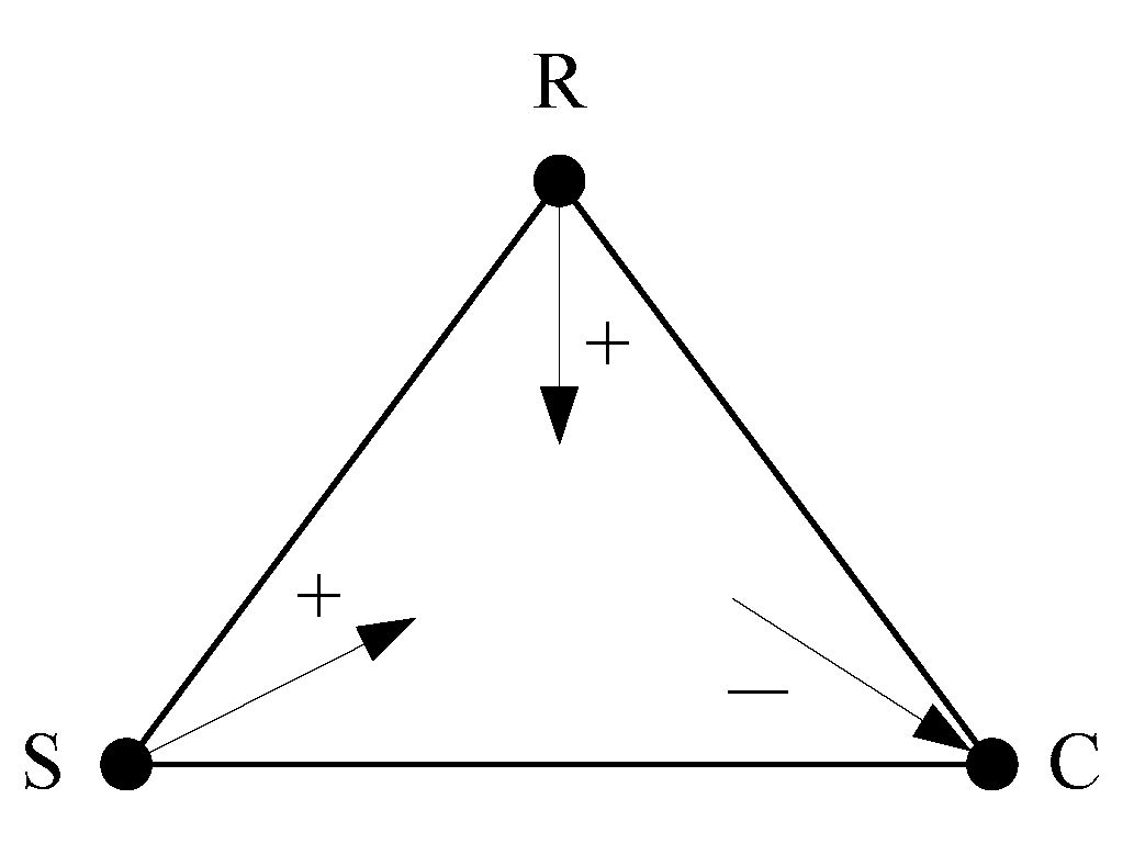
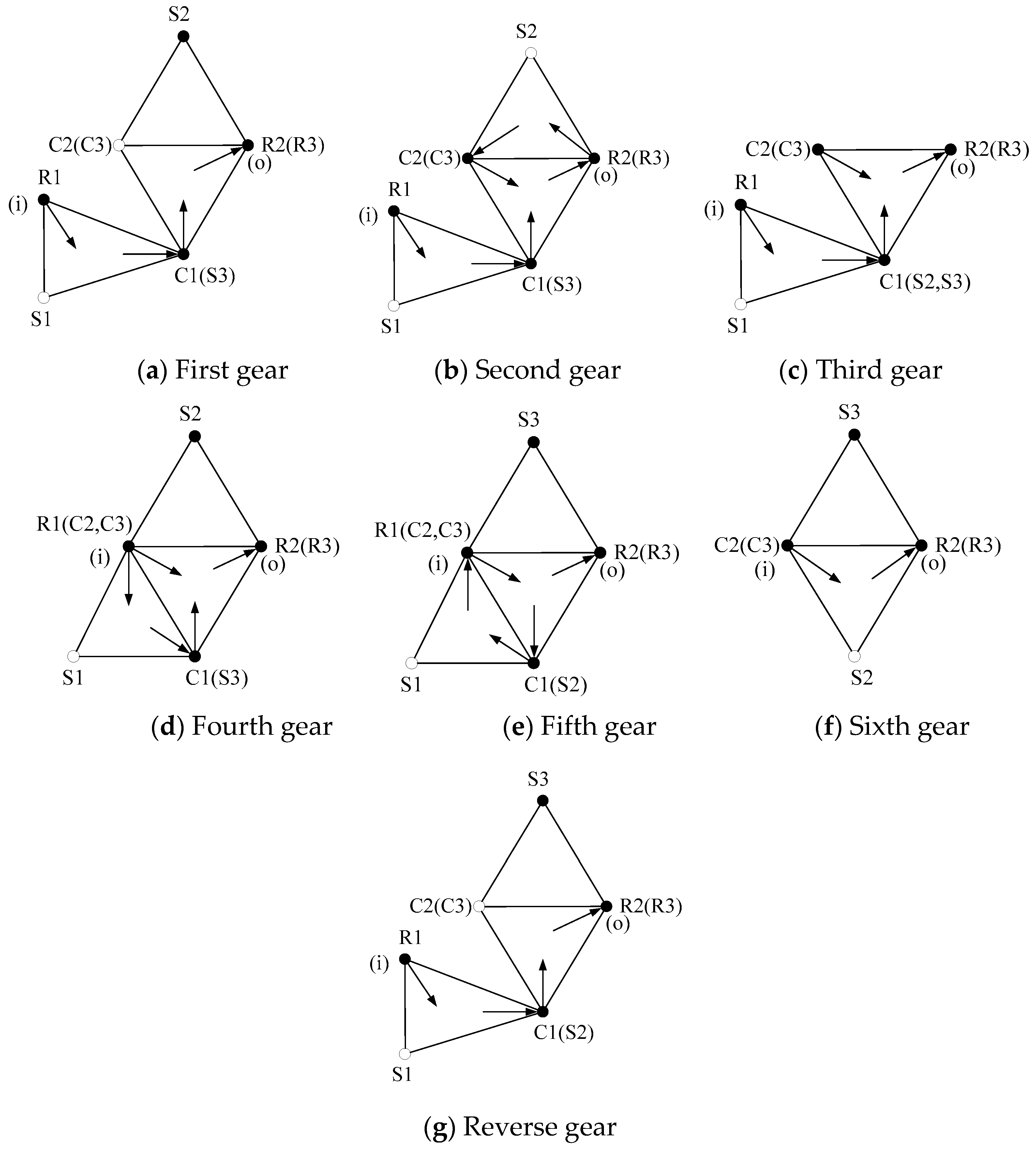
From the motion and moment analysis of automatic transmission, the rotational speed and torque of each component can be obtained respectively, thus the power flow of automatic transmission can be determined. If the component power is positive, it is input power; if the component power is negative, it is output power. The power flow diagram of a planetary row is shown in
Figure 5. The arrow inward represents the input power and the arrow outward represents the output power.
(2) Efficiency analysis
At present, there are many methods to determine planetary gear transmission efficiency. In this paper, the transmission ratio method is used to calculate transmission efficiency.
For a transmission composed of
k planetary rows, the efficiency of each gear
In formula (11), is the transmission efficiency of a planetary row. Denote the transmission efficiency of an external meshing gear pair as and the transmission efficiency of an internal meshing gear pair as , then, for a single-star planetary row , for a double-star planetary row . Usually, , .
In addition, in formula (11),
3. Performance Analysis Example of Automatic Transmission
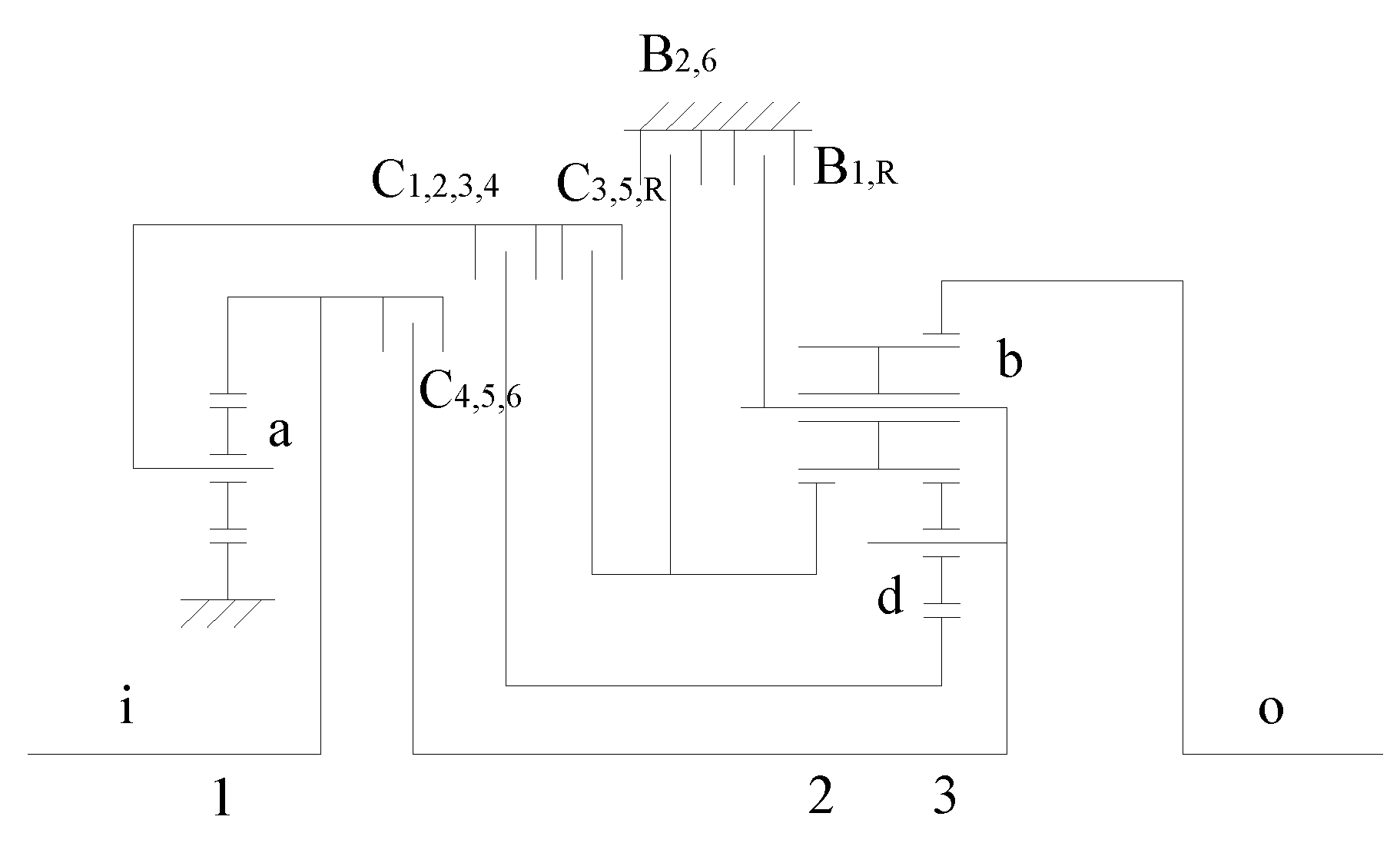
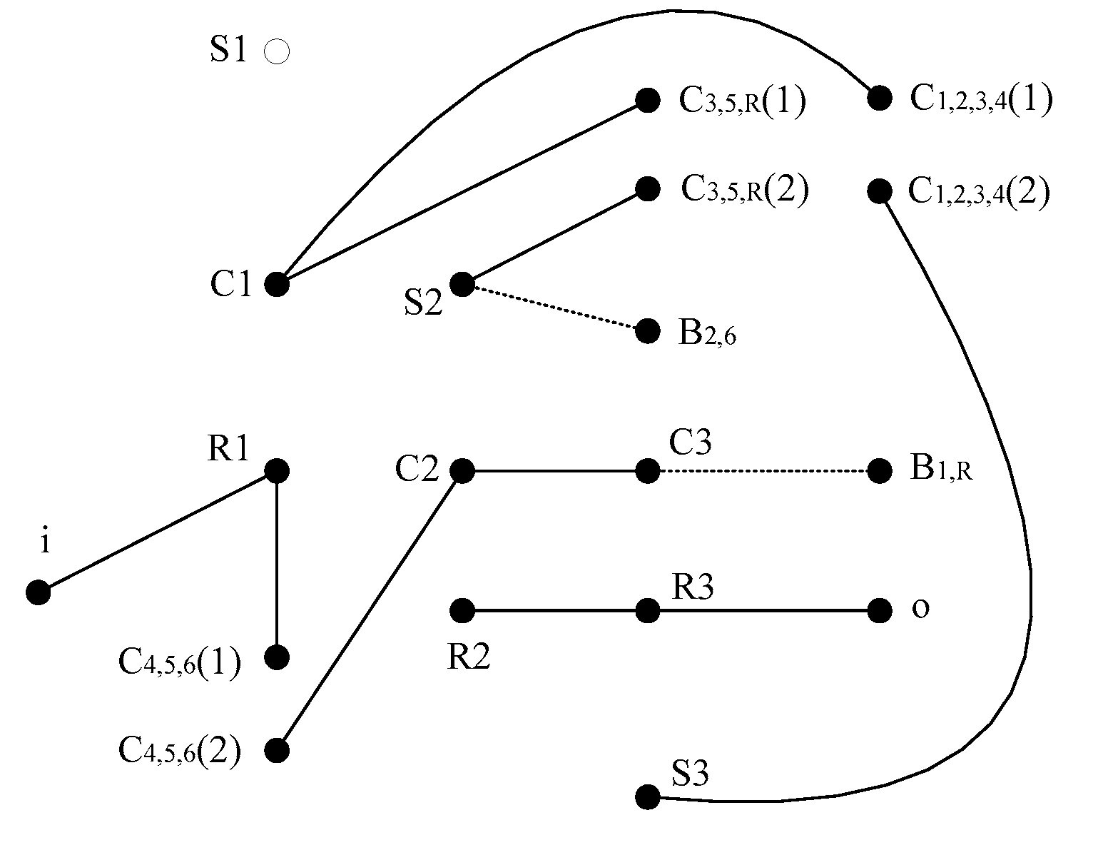
Figure 6 is a schematic diagram of 6HP26 automatic transmission developed by German ZF company. Planetary wheel of the first planetary row is represented by a. Long planetary wheel and short planetary wheel of the third planetary row are represented by b and d, respectively. 6HP26 automatic transmission will be taken as an example to analyze its motion, moment, power flow and efficiency.
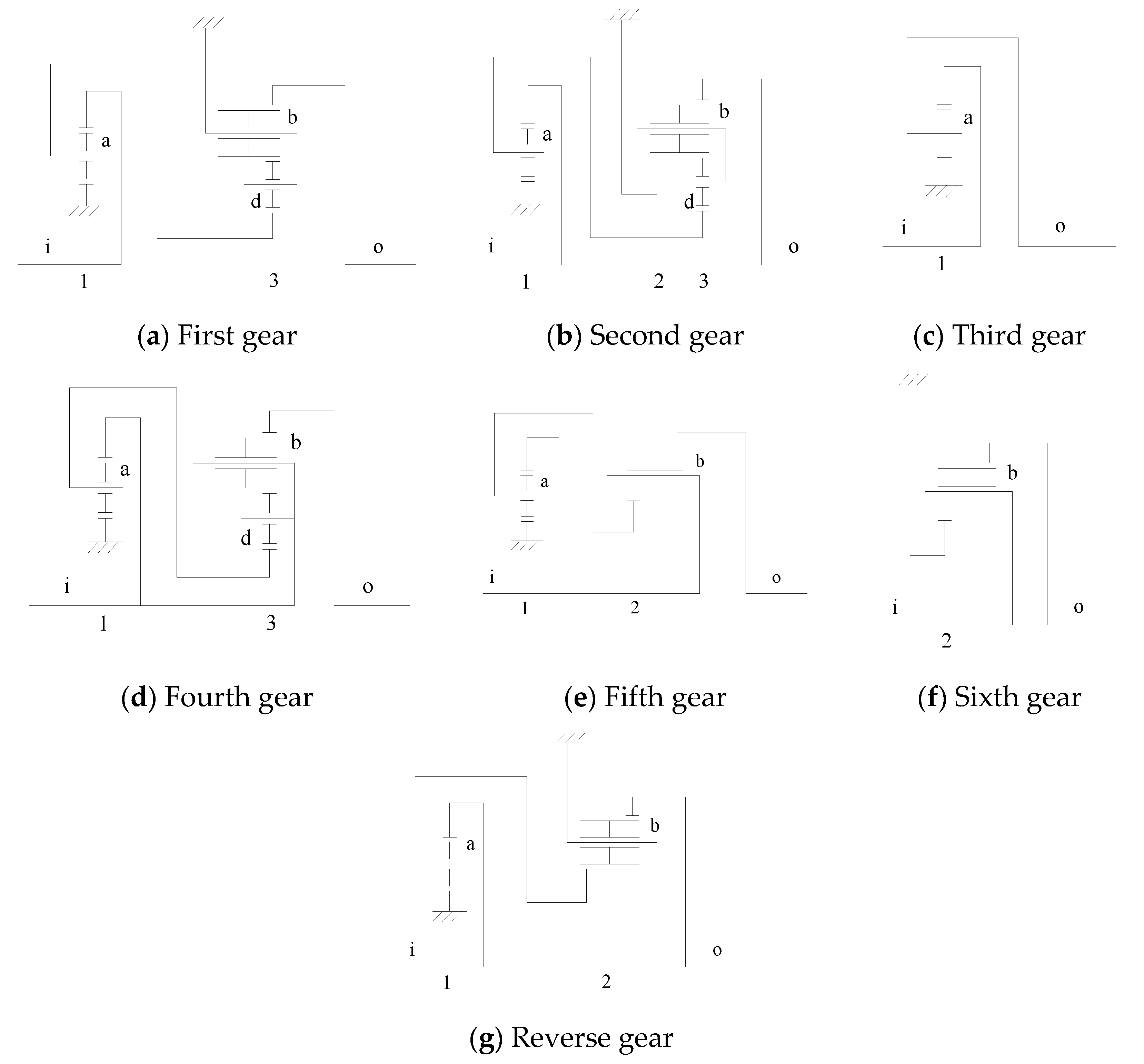
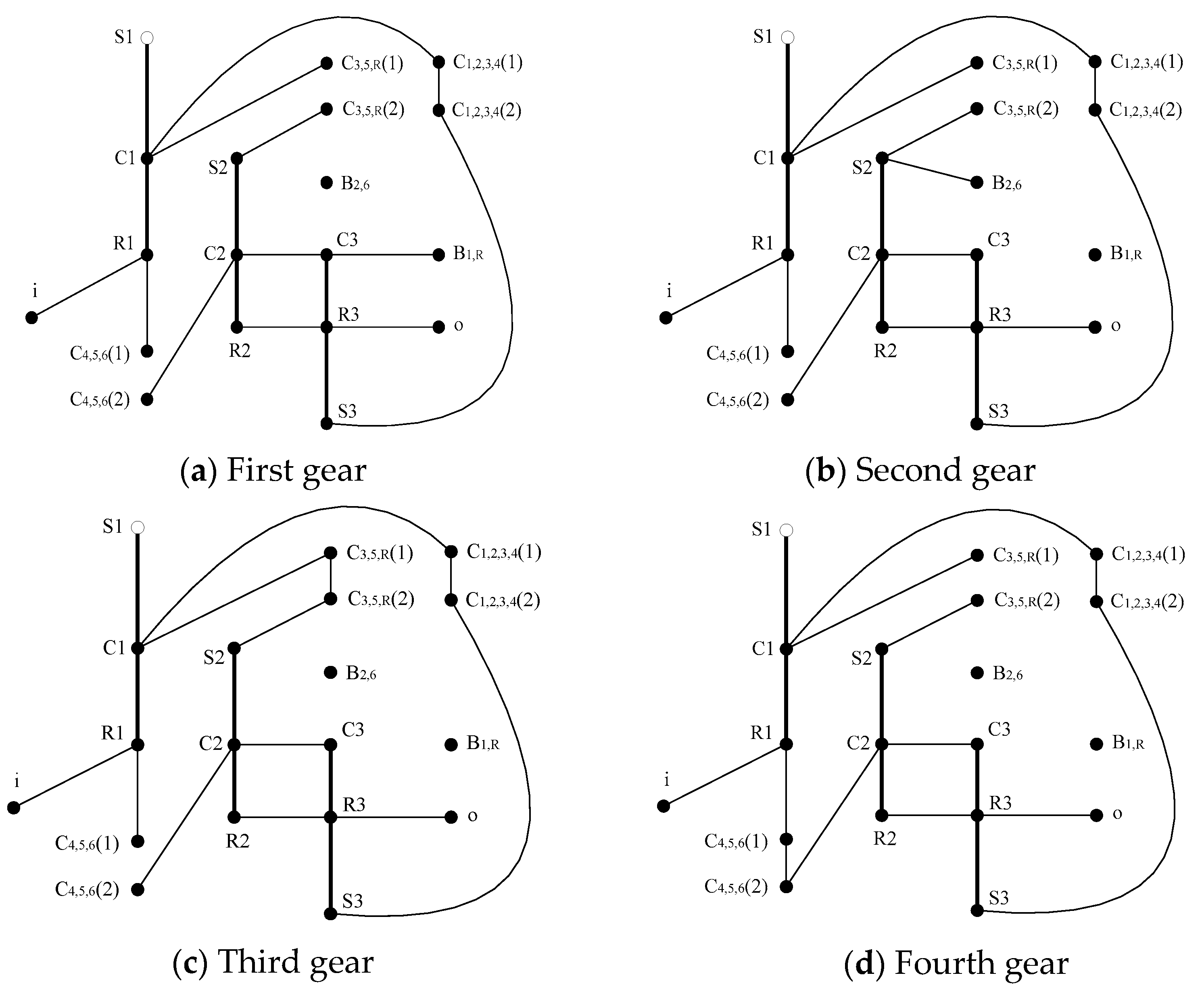
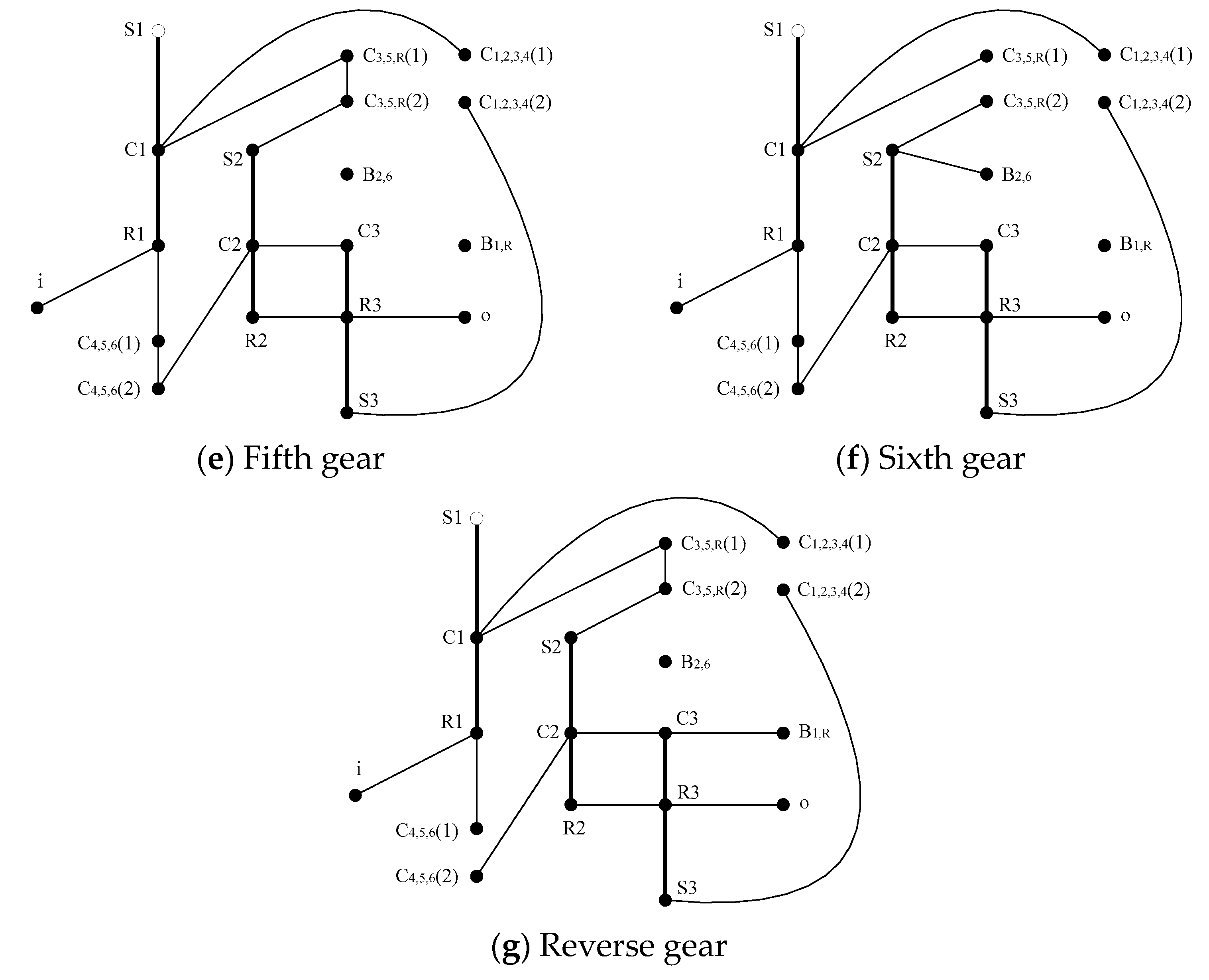
6HP26 automatic transmission can realize four reduction gears, two overdrive gears and one reverse gear. The status table of control elements is shown in
Table 2. The transmission diagram of 6HP26 automatic transmission in each gear is shown in
Figure 7, and gear ratio of each gear is shown in
Table 3.
The number of teeth of sun gear, ring gear and planetary gear for the first planetary row of 6HP26 automatic transmission is , and respectively; the number of teeth of sun gear, ring gear and planetary gear for the second planetary row is , and respectively; and the number of teeth of sun gear, ring gear, long planetary gear and short planetary gear for the third planetary row is , , and respectively. Input speed , input moment .
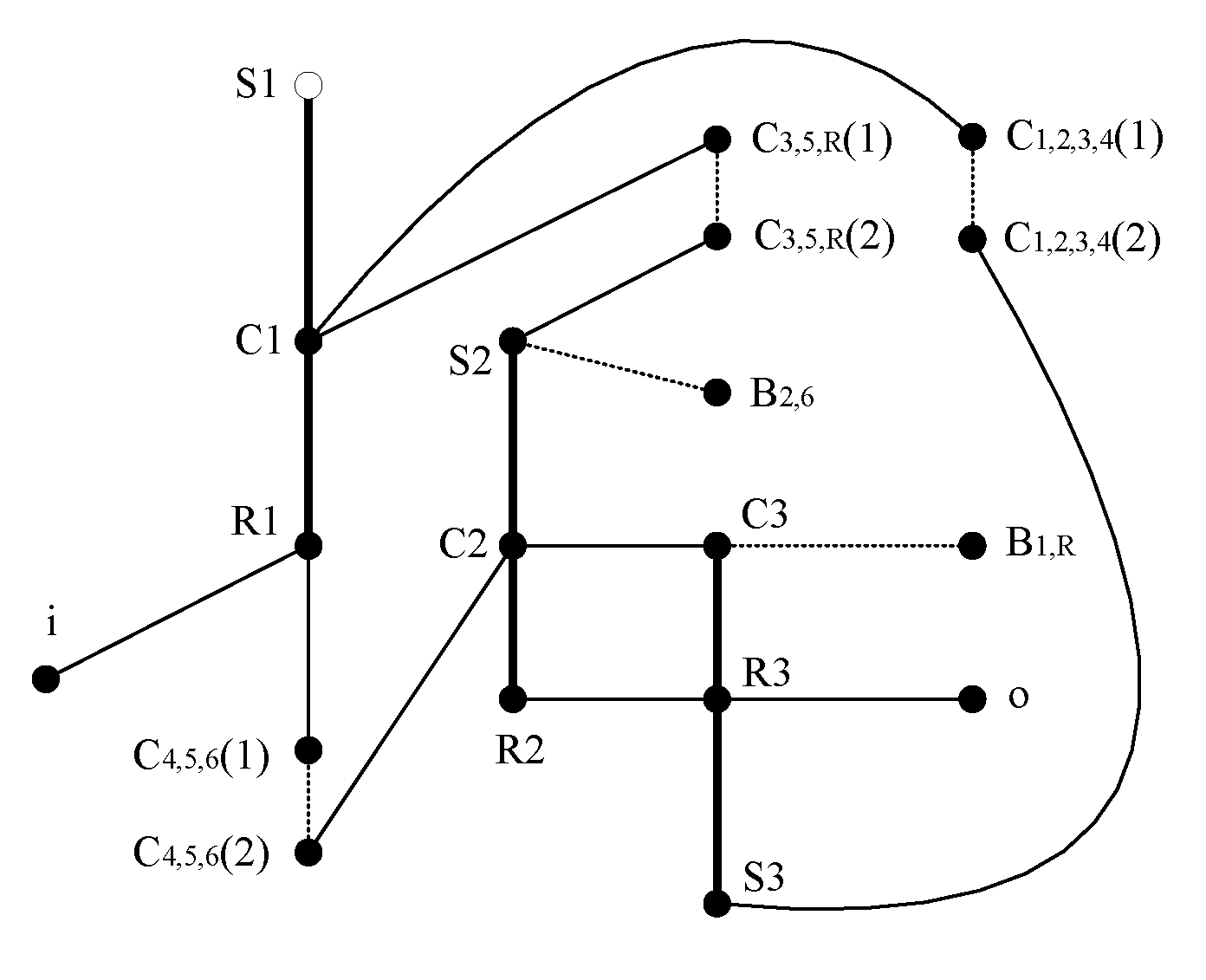
The performance analysis model of 6HP26 automatic transmission is shown in
Figure 8. The dotted line edge in
Figure 8 indicates that the connection between components is controlled by control elements.
In
Figure 8, 6 connected branches can be obtained by deleting the connecting edges between basic components of each planetary row and the connecting edges between vertices of the active and passive edges of the clutch,as shown in
Figure 9. The degree of freedom of 6HP26 automatic transmission W=6-3=3.
According to the engagement of control elements, the analysis model of each gear can be obtained, as shown in
Figure 10.
3.1. Motion Analysis
The motion analysis model of each gear of 6HP26 automatic transmission can be obtained by deleting the connection edges between basic components of each planetary row in
Figure 10.
Components of the first, second and third planetary row are numbered 1, 2, ..., 9 in the order of sun gear, ring and planet carrier, and rotational speed of the components is , , ..., , respectively. Characteristic parameter of the first, second and third planetary row , , .
Motion characteristic matrix of 6HP26 automatic transmission
The transmission ratio and component speed of 6HP26 automatic transmission at each gear can be obtained from the following equation, as shown in
Table 4 and
Table 5 respectively.
3.2. Moment Analysis
In
Figure 10, delete the connection edges between basic components of each planetary row,the connection edges between vertices of active and passive edges of the engaged clutches, and the vertices of disengaged clutches, the moment analysis model of each gear of 6HP26 automatic transmission can be obtained.
Components of the first, second and third planetary row are numbered 1, 2, ..., 9 in the order of sun gear, ring and planet carrier, and moment of the components is , , ..., , respectively.
Moment characteristic matrix of 6HP26 automatic transmission
Independent member matrix without external force
The component moment of 6HP26 automatic transmission at each gear can be obtained from the following equation, as shown in
Table 6.
3.3. Power Flow and Efficiency Analysis
From
Table 5 and
Table 6, component speed and moment can determine the power flow. Power flow diagram of 6HP26 automatic transmission at each gear is shown in
Figure 11.
According to the transmission ratio of each gear in
Table 4, the efficiency of 6HP26 automatic transmission at each gear can be obtained from Formula (9), as shown in
Table 7.
It can be seen that the efficiency is low in the first gear, second gear and reverse gear, because it is series connection in these gears.
4. Conclusion
Multi-speed PGTs improve fuel economy and dynamic performance. Therefore, a novel graph theory method is proposed in this paper for the performance analysis of automatic transmission. Taking 6HP26 automatic transmission as an example, the performance analysis model is established, and the motion, moment, power flow and efficiency analysis are completed.
This method is entirely dependent on the matrices, and performance analysis is performed automatically. In contrast to other analysis methods, this proposed method reduces the dependence on previous design experience and beforehand works of engineers. It also overcomes the disadvantages of using traditional analytical method, such as the need to repeatedly derive formulas and the complexity of calculation. And the automatic analysis of motion, moment, power flow and efficiency is realized by computer, which improves the calculation efficiency and accuracy of planetary transmission performance analysis. Moreover, This method also helps to guide the further design of the PGT, such as the geometrical parameter design of the gears.
Author Contributions
Writing—original draft preparation, H.-L.X.; funding acquisition, L.-J.L. All authors have read and agreed to the published version of the manuscript.
Funding
This work was financially supported by National Natural Science Foundation of China(No. 52005158).
Institutional Review Board Statement
Not applicable.
Informed Consent Statement
Not applicable.
Data Availability Statement
Not applicable.
Conflicts of Interest
The authors declare no conflict of interest.
References
- Gaertner, L.; Ebenhoch, M. The ZF automatic transmission 9HP48 transmission system, design and mechanical parts. SAE Int. J. Passeng. Cars-Mech. Syst. 2013, 6, 908–917. [Google Scholar] [CrossRef]
- Suzuki, T.; Sugiura, H.; Niinomi, A.; Maezuka, S.; Miyazaki, T.; Habata, Y. New RWD 10 speed automatic transmission for passenger vehicles, SAE Int. J. Engines 2017, 10, 695–700. [Google Scholar]
- Salgado, D.R.; Del Castillo, J.M. Analysis of the transmission ratio and efficiency ranges of the four-, five-, and six-link planetary gear trains, Mech. Mach. Theory 2014, 73, 218–243. [Google Scholar] [CrossRef]
- Hwang, W.M.; Huang, Y.L. , Connecting clutch elements to planetary gear trains for automotive automatic transmissions via coded sketches. Mech. Mach. Theory 2011, 46, 44–52. [Google Scholar] [CrossRef]
- Tsai, M.C.; Huang, C.C.; Lin, B.J. Kinematic analysis of planetary gear systems using block diagrams, J. Mech. Des. 2010, 132, 065001. [Google Scholar] [CrossRef]
- Geitner, G.H.; Komurgoz, G. Key characteristics of generic bond graphs for planetary gears, Mech. Mach. Theory 2022, 178, 105082. [Google Scholar] [CrossRef]
- Dong, P.; Zuo, S.M.; Liu, T.Y.; Xu, X.Y.; Guo, W.; Liu, Y.F.; Wu, H.C.; Wang, S.H. A matrix-based method for searching configurations of planetary gear trains, Mech. Mach. Theory 2023, 180, 105161. [Google Scholar] [CrossRef]
- Prikhod’ko, A.A.; Smelyagin, A.I. Kinematics of a planetary train with elliptical gears with internal gearing, J. Mach. Manuf. Reliab. 2021, 50, 412–418. [Google Scholar] [CrossRef]
- Chen, H.; Chen, X.A. Recirculation of parallel-connected planetary gear trains, Chin. J. Mech. Eng. 2022, 35, 1–11. [Google Scholar]
- Zhang, C.; Dong, H.M.; Dong, B.; Wang, D.L. A bi-directional drive model for lost motion behavior of planetary gear train, Mech. Mach. Theory 2022, 174, 104885. [Google Scholar] [CrossRef]
- Yang, W.J.; Ding, H.F.; Zi, B.; Zhang, D. New graph representation for planetary gear trains, J. Mech. Des. 2018, 140, 012303. [Google Scholar] [CrossRef]
- Hussen, H.A.; Esmail, E.L. Application of incidence matrix to topological structure and kinematic analysis of multi-planet gear trains. Results Eng. 2021, 12, 100305. [Google Scholar] [CrossRef]
- Xie, T.L.; Hu, J.B.; Liu, C.W. Synthesis of seven-speed planetary gear trains for heavy-duty commercial vehicle, Mech. Mach. Theory 2015, 90, 230–239. [Google Scholar] [CrossRef]
- Ke, T.; Ding, H.F.; Gong, C.; Geng, M.J. Configuration synthesis of nine-speed automatic transmissions based on structural decomposition, Mech. Mach. Theory 2021, 164, 104421. [Google Scholar] [CrossRef]
- Dong, P.; Liu, Y.F.; Tenberge, P.; Xu, X.Y. Design and analysis of a novel multi-speed automatic transmission with four degrees-of-freedom. Mech. Mach. Theory 2017, 108, 83–96. [Google Scholar] [CrossRef]
- Esmail, E.L. A matrix-based method for detection of degenerate structures in planetary gear trains, Mech. Mach. Theory 2022, 175, 104925. [Google Scholar] [CrossRef]
- Shivam, M.; Arun, D.D.; Karuna, M.; Manjula, D. Efficiency analysis of dual motor powertrain with planetary gear set, Int. J. Emerg. Electr. Power Syst. 2022, 1. [Google Scholar]
- Ge, Y.J.; Liu, D.N. Transmission efficiency and optimization of the power-confluence magnet planetary gear, J. Power Electron. 2022, 22, 1–10. [Google Scholar] [CrossRef]
- Yang, J.Y.; Ge, Y.J. Transmission performance of planetary permanent magnet gear with few pole difference, J. Mech. Sci. Technol. 2022, 36, 6217–6225. [Google Scholar] [CrossRef]
- Mohite, D.D.; Patil, N.R.; Shinde, S.B.; Rade, K.A. Experimental investigation on speed and torque analysis of planetary gearing system, J. Algebr. Stud. 2022, 13, 1439–1446. [Google Scholar]
- Ding, H.F.; Cai, C.W.; Chen, Z.M.; Ke, T.; Mao, B.W. Configuration synthesis and performance analysis of 9-speed automatic transmissions. Chin. J. Mech. Eng. 2020, 33, 1–21. [Google Scholar] [CrossRef]
- Liao, Y.G.; Chen, M.Y. Analysis of multi-speed transmission and electrically continuous variable transmission using lever analogy method for speed ratio determination. Adv. Mech. Eng. 2017, 9, 1–12. [Google Scholar] [CrossRef]
- Kahraman, A.; Ligata, H.; Kienzle, K.; Zini, D.M. A kinematics and power flow analysis methodology for automatic transmission planetary gear trains. J. Mech. Des. 2004, 126, 1071–1081. [Google Scholar] [CrossRef]
- Liu, J.X.; Yu, L.D.; Zeng, Q.L.; Li, Q.Y. Synthesis of multi-row and multi-speed planetary gear mechanism for automatic transmission, Mech. Mach. Theory 2018, 128, 616–627. [Google Scholar] [CrossRef]
- Yang, X.D.; Shao, Y.M.; Wang, L.M.; Yu, W.N.; Yue, N.; Du, W.T. Configuration design of dual-input compound power-split mechanism for in-wheel motor-driven electrical vehicles based on an improved lever analogy method, J. Mech. Des. 2021, 143, 1–12. [Google Scholar] [CrossRef]
- Deng, T.; Gan, Z.H.; Xu, H.; Wu, C.J.; Zhang, Y.X.; Liu, F.; Ding, Z.T.; Chen, W. Configuration design and screening of multi-mode double-planetary-gears hybrid powertrains, J. Mech. Des. 2022, 144, 073301. [Google Scholar] [CrossRef]
- Jiang, X.Y.; Hu, J.J.; Peng, H.; Chen, Z.P. A design methodology for hybrid electric vehicle powertrain configurations with planetary gear sets, J. Mech. Des. 2021, 143, 1–10. [Google Scholar] [CrossRef]
- Timofeev, G.A.; Panyukhin, V.V.; Sashchenko, D.V. Studying self-braking planetary gears with single-crown satellites, J. Mach. Manuf. Reliab. 2020, 49, 308–313. [Google Scholar] [CrossRef]
- Prikhodko, A. Experimental kinematic analysis of an intermittent motion planetary mechanism with elliptical gears, J. Meas. Eng. 2020, 8, 122–131. [Google Scholar] [CrossRef]
- Zanasi, R.; Tebaldi, D. Modeling of complex planetary gear sets using power-oriented graphs, IEEE Trans. Veh. Technol. 2020, 69, 14470–14483. [Google Scholar] [CrossRef]
|
Disclaimer/Publisher’s Note: The statements, opinions and data contained in all publications are solely those of the individual author(s) and contributor(s) and not of MDPI and/or the editor(s). MDPI and/or the editor(s) disclaim responsibility for any injury to people or property resulting from any ideas, methods, instructions or products referred to in the content. |
© 2023 by the authors. Licensee MDPI, Basel, Switzerland. This article is an open access article distributed under the terms and conditions of the Creative Commons Attribution (CC BY) license (http://creativecommons.org/licenses/by/4.0/).
