1. Introduction
The current understanding of the Earth’s internal structure, including the crust, mantle, and core, is largely based on data gathered through seismology [
1]. While numerous broadband seismic networks have been established worldwide, the scarcity of offshore seismic stations has posed a significant challenge for global-scale tectonic and structural studies. Despite that the Ocean Bottom Seismometer (OBS) has long been used to detect deep seafloor structures, it still has some limitations such as short working time, limited coverage, and high investigation costs, making it unsuitable for large-scale seismic stratigraphic imaging on a global scale [2, 3]. To address these issues, Professor Nolet proposed the use of a Mobile Earthquake Recording in Marine Areas by Independent Divers (MERMAID), which can move with ocean currents to achieve large-scale seismic observation at sea [
4]. In 2003, a prototype was successfully developed, capable of diving down to the maximum depth of the seafloor and recording a magnitude 6 seismic signal from a distance of 5000km.
Currently, operating mobile ocean seismographs move with ocean currents at a rate of nearly 4 km per day [
4]. We are facing two problems: a single movable seismograph is current blow to the shore, premature loss of earthquake observation function; Or the seismograph may not be in the ideal position to observe earthquakes following ocean currents, yielding data that does not reveal global structure. Therefore, the development of a Marine seismometer system with mobility and networking function can realize near-real-time and large-scale long-term observation of seabed seismic signals, lay a solid foundation for Marine seismic research and the study of earth structure, activity and process, and support seismic monitoring into the deep sea.
This paper presents a proposed design for a mobile ocean seismometer, which includes a brief overview of its structure, design, and mode of operation. The ballast chamber structure is given particular attention, with a study of its design combined with the working mode. An ellipsoid ballast tank composed of 7075-T6 aluminum alloy is designed to meet the necessary specifications. The yield ultimate strength of the ballast tank is obtained through theoretical calculation and finite element simulation, and the results are thoroughly compared and analyzed to ensure that the ultimate strength meets all service requirements.
2. Materials and Methods
2.1. Design indicators and working modalities
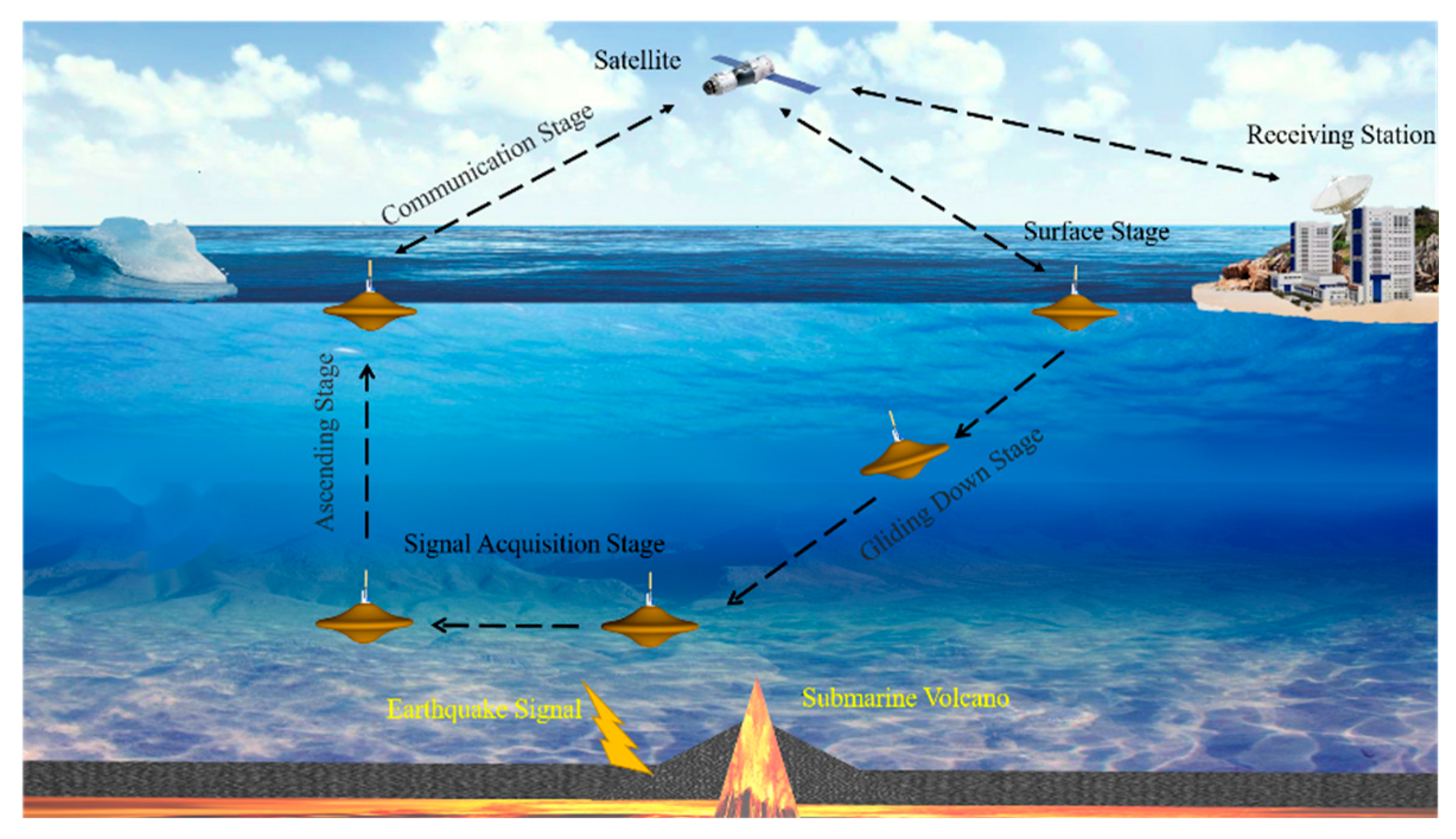
The AGMS mainly consists of seven parts: a pressure-resistant chamber, observation module, energy module, buoyancy adjustment module, center of gravity adjustment module, central control module, and monitoring module. According to the requirements, the maximum working depth of the seismometer is 2000 m, the maximum sinking and floating speed is 0.35 m/s, and the weight is less than 200 kg. According to the actual application requirements, the working mode of the AGMS can be changed, and the buoyancy adjustment can be used to autonomously complete the basic tasks such as diving, hovering and floating, and the process of its repeatability is high, and a typical cyclic profile can be divided into five phases (shown in
Figure 1).
Surface stage: The AGMS floats on the surface of the water under maximum buoyancy, with the upper antenna exposed to the water surface to complete the self-test and surface test to ensure that there are no errors in the various commands, and then waits for the mission command.
Glide down stage: After receiving instructions to descend, remain unchanged, and its gravity drainage volume, change AGMS adjustment for negative buoyancy state, start by variable speed run to the approximate uniform descend; At the same time, you can adjust the direction and glide Angle to glide to the target area.
Signal acquisition stage: The AGMS is lowered to the desired depth and adjusts its buoyancy to match gravity, achieving a neutral buoyancy state. At this point, the hydrophone is activated to monitor underwater acoustic signals, and any seismic waves detected are recorded, with P-wave information being captured and stored for data analysis. Specifically, data from 2 to 5 minutes before and after the maximum wave peak is intercepted and saved. If no seismic waves are detected, the device will automatically surface after 7 days of drifting with ocean currents.
Ascending stage: During the ascending stage, the AGMS turns off its hydrophone and adjusts to a positive buoyancy state before accelerating to a uniform speed and floating to the surface.
Communication stage: Activate the communication module and allow the AGMS’s antenna to surface, maintaining contact with the monitoring centre for GPS positioning and data transmission. Due to the influence of ocean currents, it is allowed to have an error of about 500m between the seismic sampling point and the positioning coordinates, and after the transmission is completed, the clock is calibrated to enter the next cycle.
2.2. Design solutions for carrier profiles and pressure-resistant structures
At present, the main long-period observation platforms are the self-sinking profiling buoy-type ocean observation platform [5, 6] (Array for Real-time Geostrophic Oceanography, Argo), and the underwater glider [
7]. However, these detectors have the following deficiencies in seismic observation: the long column structure of Argo is prone to swaying during underwater observation and, like MERMAID, will face drifting with ocean currents; Glider has the ability of long-term maneuvering observation, but it is suitable for continuous sawtooth observations and is not suitable for long-term fixed depth hovering observation. Argo’s long column structure is not conducive to seismic observation, and like MERMAID, it will face drifting with the ocean currents; Glider has the ability of long-term maneuvering observation, but it is suitable for continuous sawtooth observation, not suitable for long-term fixed-depth hovering observation.
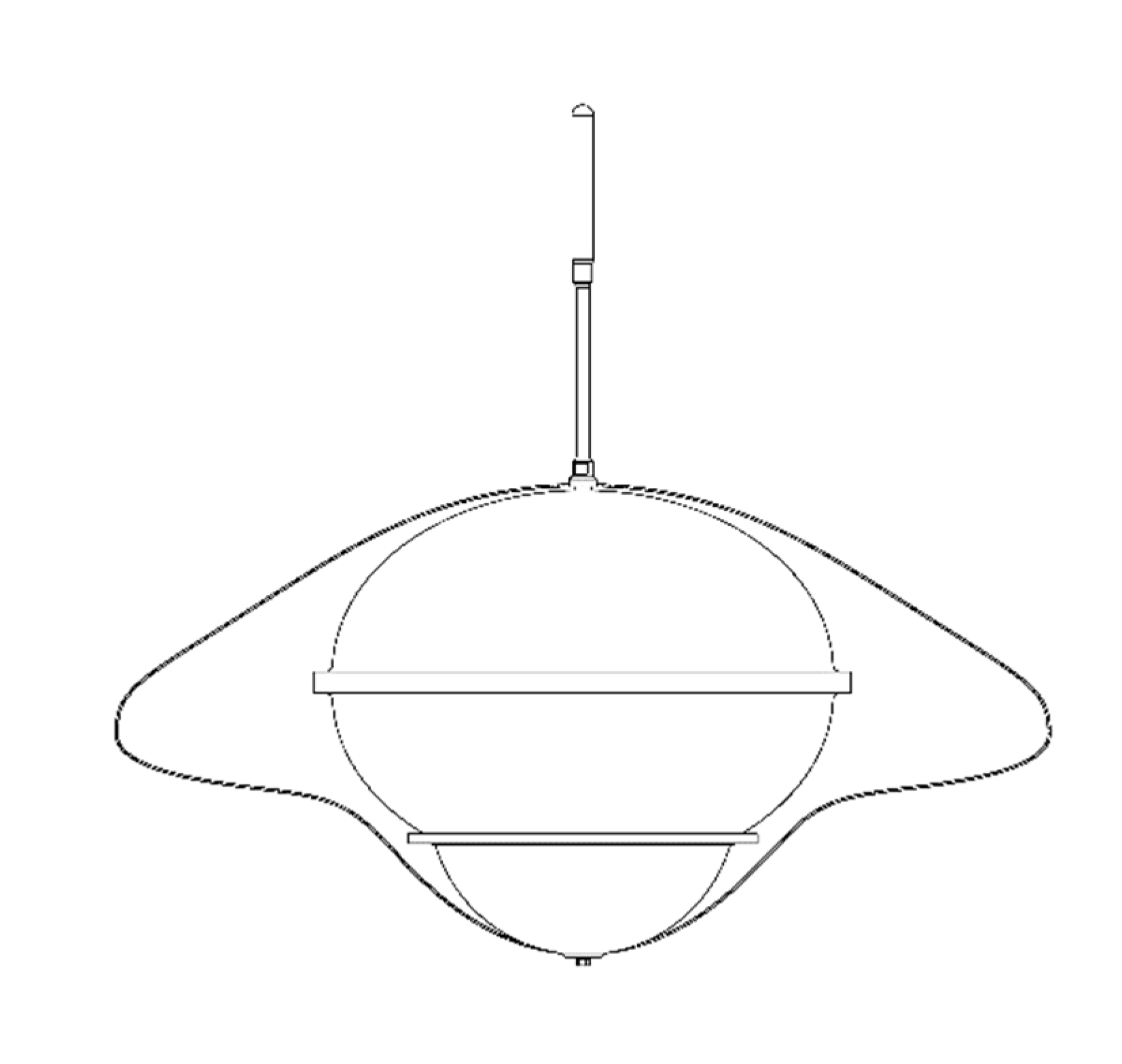
After analyzing the pros and cons of the observation platform mentioned earlier, we have determined that a circular disk shape is the ideal carrier design. The disk-shaped submersible boasts the same benefits as traditional underwater gliders, including low energy consumption, extended endurance, remote monitoring capabilities, and more. In addition, its smaller steering space allows for increased flexibility in various angles and directions. The rotating shape is also less affected by complex currents, making it suitable for long-term fixed-depth hovering observation. Plus, the disk shape’s hydrodynamic characteristics and superior motion stability make it a better choice than a spherical shape. However, due to the mission’s focus on designing a motorized marine seismometer gliding dive lift resistance ratio, we must consider an asymmetric disc-shaped shell with a 1300mm diameter and 650mm height. While one-piece molding is difficult, and the structural strength is insufficient, increasing the shell’s thickness to meet the pressure resistance results in a heavier overall weight and higher manufacturing costs. Additionally, adding internal strengthening structures will affect the internal space layout. Thus, to reduce processing costs and improve internal space utilization, we have adopted a pressure-resistant cabin plus fairing combination approach, as shown in
Figure 2.
3. Pressure-resistant chamber design
The stability, strength, and sealing of the pressure-resistant chamber are critical to the proper functioning of the motorized marine seismograph. The buoyancy of the equipment is primarily determined by the weight ratio of the chamber to the drainage weight. Therefore, it is crucial to prioritize the stability of the pressure chamber in the design process and minimize its weight and drainage weight ratio.
3.1. Structural form and material selection
Pressure tanks come in different shapes, including spherical, ellipsoidal, and cylindrical. Spherical tanks are preferred for submersible vessels that go deeper than 800 meters because of their strength and working environment. To create a pressure tank with high internal space utilization, good quality, and the added benefit of joint circular disc enclosure, designers use a combination of two ellipsoidal head pressure tanks. The ballast tank’s material is made of 7075-T6 aluminium alloy [
8], known for its excellent plasticity, heat treatment, and low-temperature strength after solution treatment. This material is commonly used for high-stress structural parts that need high strength and strong corrosion resistance. Please refer to
Table 1 for the geometric and physical parameters of the ballast tank design.
3.2. Base material thickness calculation and design
The maximum working pressure of the withstand capsule is 20MPa, which is formed by die forging and milling. To reduce the redundant weight, according to the standard [
9] and Rules For Classification Of Diving Systems And Submersibles [
10] (CCS), the design temperature is 2℃, the allowable stress safety factor is
S =0.85, and the calculated pressure safety factor
K is 1.25, namely
Pj=25MPa; known yield stress
σ for 7075-T6 materials 440MPa, then the allowable stress of the material is:
When subject to external pressure as per the CCS guidelines (refer to
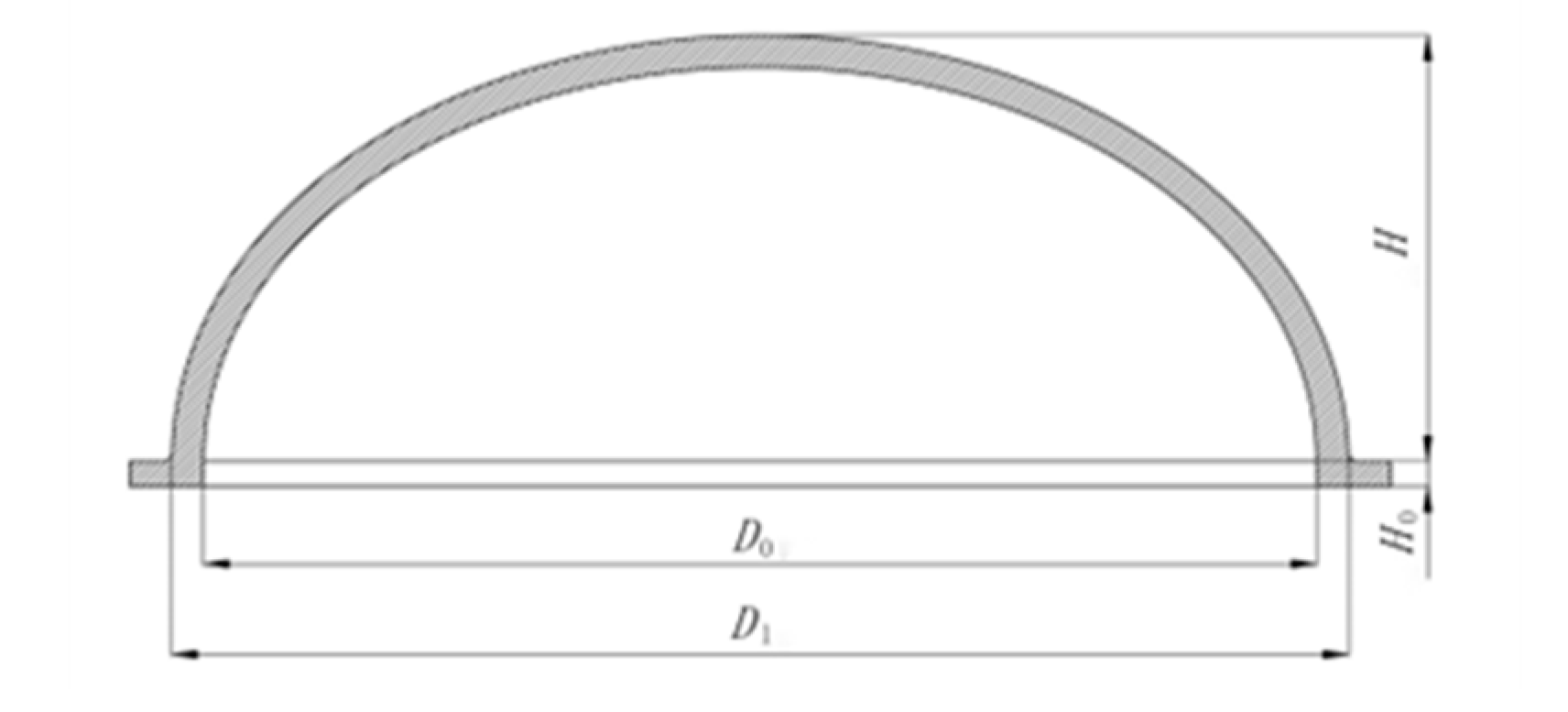
Figure 3), ellipsoidal heads must undergo strength and stability calibration in line with its subsections 4.6.2.1 and 4.6.3.1 respectively. During calibration, the equivalent radius
Rd (mm) is employed as the radius of the spherical shell, and it is calculated using the following formula:
In formula: D0 is the ellipsoid inner diameter, mm; D1 is ellipsoid outer diameter, mm; H is the ellipsoid depth, mm.
Calculate the stress of the pressure chamber:
The thickness of the pressure capsule is calculated according to the following formula:
Where:
y elliptic head shape factor [
9], which is 0.66;
Pj is the calculated pressure, Mpa;
th is the calculated thickness of the head, mm;
D1 is the inner diameter of the head, mm; [
σ]
t material allowable stress at room temperature, Mpa; φ is the welded joint coefficient, and this value is 1.0.
Replacing each design data with formula (4), available:
The nominal thickness t is the thickness rounded up after calculating the thickness th and adding the negative deviation of material thickness C1 and corrosion margin C2. Milling error C1 is 2mm, corrosion margin C2 is 1mm, and nominal thickness t ≥ 18.7mm; According to the buckling check formula in 4.6.3 of the CCS, 19mm, 20mm and 21mm thicknesses were selected for buckling calculation.
3.3 Stress calculation and check
Section 4.6.3 of CCS was used for buckling calculation and check:
Where: The elastic modulus of the 7075-T6 material is
E=71Gpa. The ratio
t/
R is used to determine
C, as shown in
Figure 4.6.3.1(2) in CCS.
Calculation of withstand capsule flexion:
Where:
Cs is determined by parameters
σe /
σs, refer to
Figure 4.3.4.1 of CCS;
Cz is determined by parameters
σe /
σs, see
Figure 4.6.3.1(1) in CCS.
Table 2.
Buckling results of different thicknesses.
Table 2.
Buckling results of different thicknesses.
|
t /mm |
19 |
20 |
21 |
| C |
06.03 |
.03072 |
0.0392 |
| CS |
0.385 |
03.37 |
0.355 |
| CZ |
0.9378 |
04.9 |
0.959 |
|
Pj/Mpa |
25 |
25 |
25 |
|
Pe/ Mpa |
77.29 |
82.53 |
91.65 |
|
Pcr/ Mpa |
27.905 |
28.92 |
31.20 |
According to the calculation results in the above table, when the thickness t=19mm, the strength meets the requirements of buckling calculation.
4. Stability analysis of the pressure-resistant chamber
As the most important pressure structure, the pressure body needs to have sufficient stability. Ensuring stability in the pressure body is of most importance. Currently, there are two methods used for this: linear buckling analysis and nonlinear buckling analysis via finite element analysis and model testing. This section effectively confirms the stability of the compression chamber through theoretical calculation and finite element analysis, with the results being thoroughly compared.
4.1. Analysis of critical instability of the resistant capsule
This paper will use linear buckling and nonlinear buckling analysis to analyze the critical instability stress, with the classical stability theory formula and Carmen-Qian Xuesen formula [
11], Specification (2018 edition), GL specification experience formula [
12], and the Taylor Pool formula [11, 13]. The calculation results are compared to analyze whether the pressure-resistant capsule can meet the use requirements.
(1) R.Zoelly The Classical Theory, also referred to as the classical small deflection solution, is an ideal approach that assumes uniform material, isotropy, and perfect geometric spheres with no initial stress. Its stress and strain are linear, resulting in calculation values that tend to be higher than actual test values.
(2) Carmen- -Qian Xuesen formula: In 1939, Karman and Qian Xuesen derived the critical pressure value of the spherical shell by using the nonlinear large deflection theory. The formula takes into account the effect of the initial defects, with
R0 being the maximum local radius.
However, the average of many experimental results shows that [
14]:
(3) The critical instability force is calculated in the GL specification as follows:
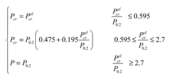
In the spherical shell elastic instability force:

;
Elastic-plastic flexion instability force:

;
Rm, l is the maximum local average radius; Ro, l is the maximum local external radius; S1 is the local shell thickness average.
(4) Taylor pool formula: The US Navy summarizes the Taylor pool formula by conducting pressure tests considering the effects of manufacturing error and residual stress.
Cz for the fabrication of influence coefficient, reference [
11] gets a value of 0.96, which is the nod for the critical arc average thickness of plate and shell;
Rcr is the local curvature radius of the outer surface of the spherical shell. Spherical shell in more than proportional limit, after the material has begun to yield for nonlinear buckling, this time with secant modulus
Es and tangent modulus
Et to handle the buckling stress, which uses double tangent modulus instead of E, the concrete solving process can be references [12, 13].
4.2. Finite-element analysis of linear buckling
We used software for finite element analysis to study the buckling of our model’s eigenvalues.
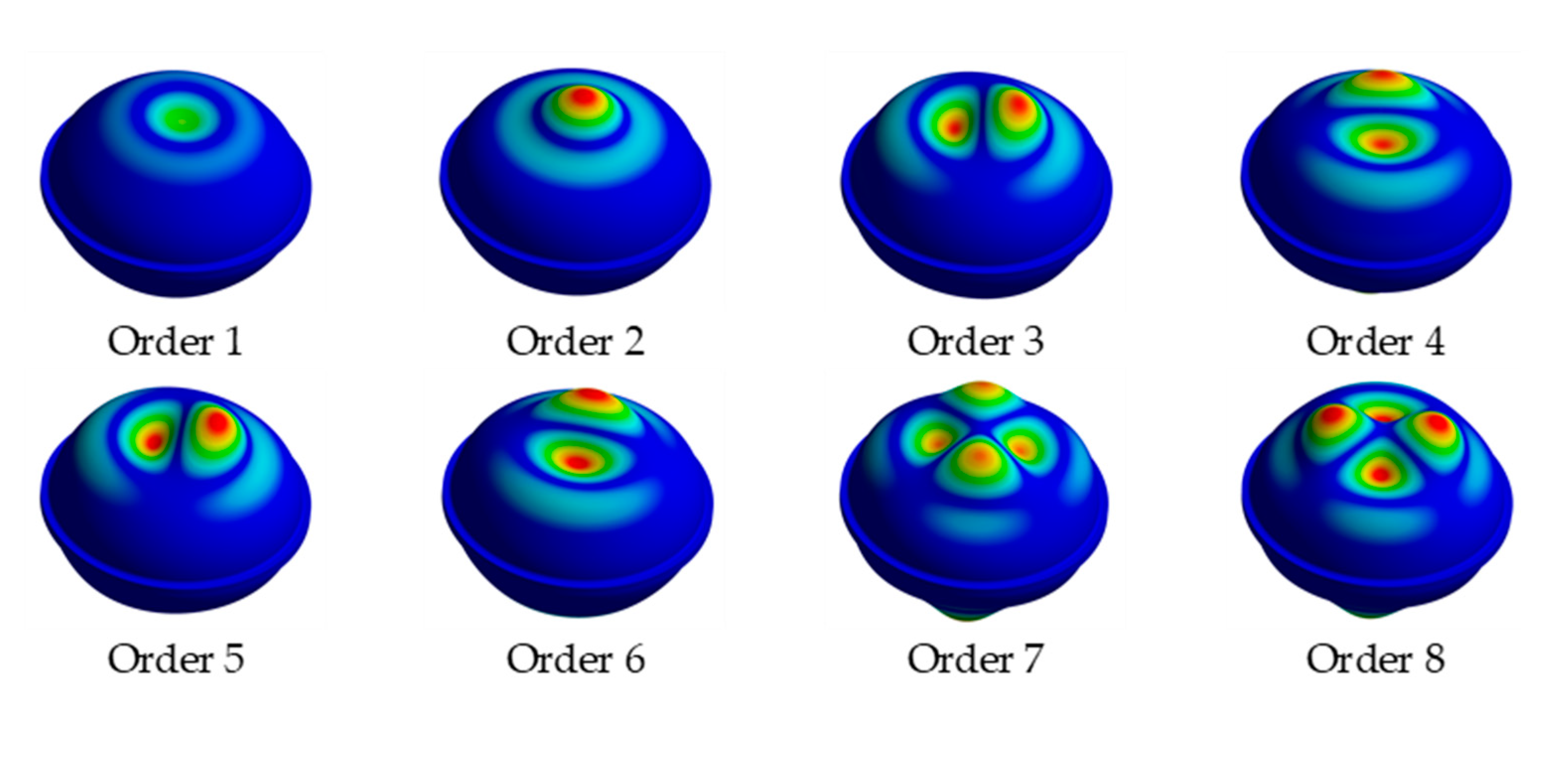
Table 1 shows the physical and geometric parameters of our model. The boundary conditions for point A and point B included X-axis displacement in the free direction but no displacement in any other direction. Point C’s Z-axis direction was free, with no displacement in other directions. We divided the grid into tetrahedron units of 15 mm, 10 mm, and 8 mm, with local grid refinement featuring 1.5 mm rounded corners. To calculate the water pressure, we applied 25MPa to the ballast tank, which resulted in the output of the first eight-order eigenvalue modes (
Figure 5). The outcomes of the first eight-order eigenvalue buckling are shown in
Table 4.
Using the classical theory of spherical shell stability, we can determine the elastic instability pressure of a model with a spherical shell of radius Rd through a theoretical formula, yielding a value of Pe=150.78MPa. Upon analyzing the results of linear buckling for the first mode of the first eight-order buckling modes of the three grids, we found that the elastic instability forces obtained were 156.9225 MPa, 156.4225MPa and 156.2475 MPa, respectively. These values are very similar to the theoretical value, indicating the error between the results obtained using a 10mm grid and the theoretical value is already very small. After conducting linear buckling finite element analysis, we replaced the value in Table 3 with the corrected result of 156.4225MPa for Pe. However, the critical instability force obtained after CCS correction was found to be 56.477Mpa.
4.3. Nonlinear flexion analysis
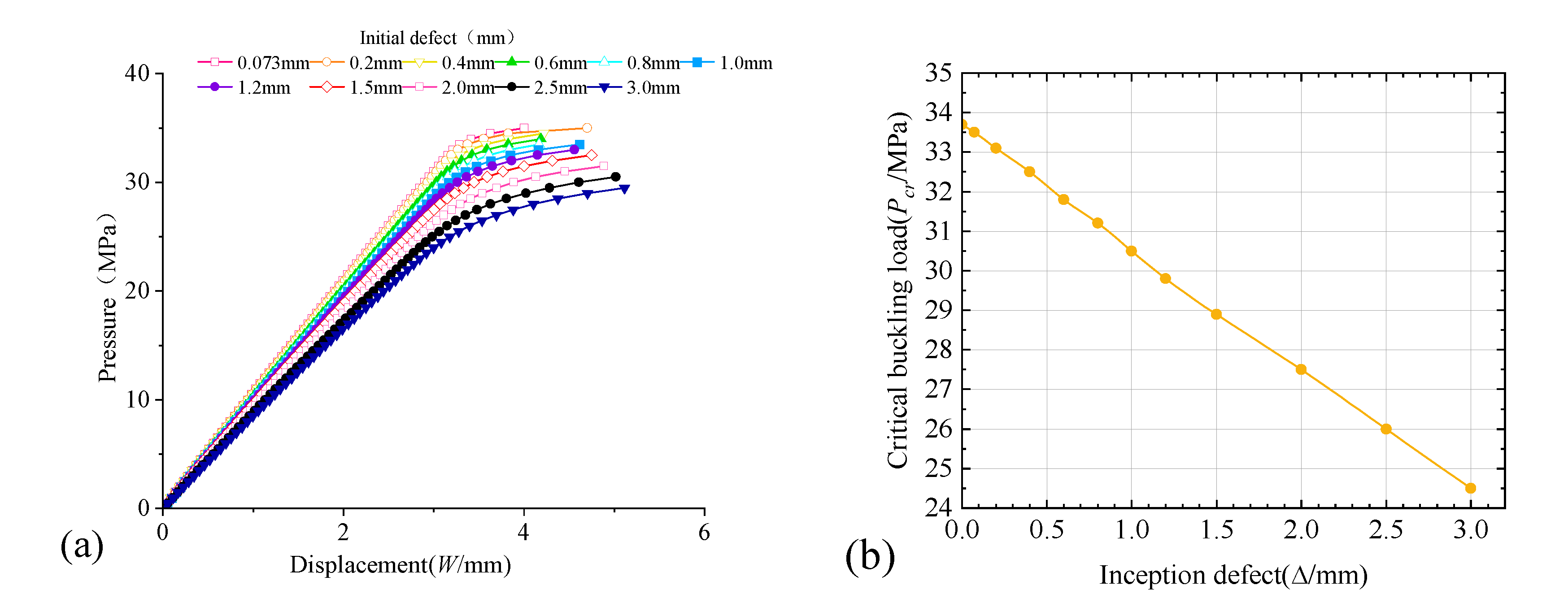
After analyzing the model for linear buckling, we determined that the critical instability force for elasticity is 156.4225MPa. To perform nonlinear buckling, we increased the pressure in the pressurization chamber beyond this value to 200MPa. This process was completed in 20000 seconds and 400 steps. To ensure the structure met the CCS requirement for a true spherical degree of 1.005, we utilized different initial deflections using the first-order eigenvalue instability mode. This replaced their influence on the structure’s stability for the nonlinear buckling analysis, with initial deflections ranging from 0 to 3mm.
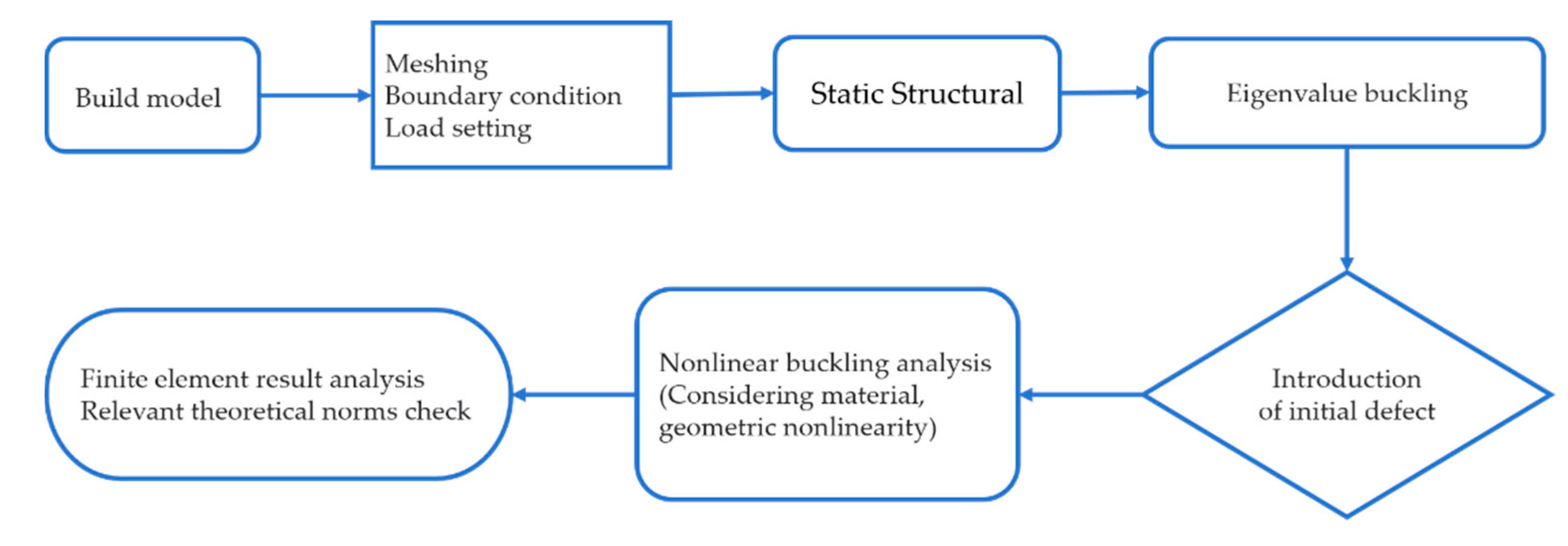
Figure 6 outlines the flow chart for the nonlinear buckling analysis. After conducting multiple calculations with varying initial deflections, we obtained the pressure and displacement curves of the pressure shell, as shown in
Figure 7(a).
According to the findings depicted in
Figure 7(b), there exists a distinct linear correlation between
Pcr and the initial deflection
f. As the initial deflection f rises,
Pcr declines consistently. To be precise, a 2 mm increase in initial deflection results in a reduction of
Pcr by 18.6%. Consequently, the size of the initial deflection plays a crucial role in the critical instability. Thus, it is essential to improve the machining precision of the pressure-resistant cabin to tackle this problem effectively.
4.4. Results analysis and comparison
In
Table 5, we see a comparison of the ballast tank’s ultimate strength calculated by different methods: empirical formula, specifications, and finite element analysis. The Karman-Qian formula produces experimental results that are closest to the CCS calculation results and are conservative compared to other methods. While some methods differ significantly, the nonlinear buckling analysis’s initial deflection result of 0.073mm is closer to the GL specification and Taylor pool formula and higher than that of CCS. The linear buckling analysis’s corrected buckling value is not suitable for use as the elastic instability pressure of the structure but can serve as a reference for nonlinear buckling analysis. In general, the various methods in the table provide reliable results for stability calculation, with even the most conservative result being greater than the calculation pressure, indicating the feasibility of the design scheme.
5. Conclusions
The AGMS is a groundbreaking piece of marine seismic observation equipment that addresses the limitations of its traditional counterparts, including limited mobility, high observation costs, and lengthy data return periods. With its capacity for long-term fixed-depth hovering observation, this technology boasts numerous potential applications in marine seismic network detection. Our research delves into the design of a pressure-resistant cabin for the motorized marine seismometer, yielding the following conclusions:
- (1)
Our paper mainly discussed the AGMS’s design index and working mode. We had accomplished the structural design of a pressure-resistant chamber and performed strength analysis and checks. Our calculations affirmed that the design strength satisfied all essential criteria.
- (2)
Our team had thoroughly researched and analyzed a multitude of specifications and standards to create an efficient and reliable pressure-resistant chamber.
- (3)
Ellipsoidal pressure-resistant compartments had limited examples and varying theoretical formulas produce differing calculation results. Additionally, there was a lack of theoretical analyses for high-strength aluminum alloys utilized in deep-sea pressure-resistant compartments. To ensure structural stability, our design considered multiple reference standards and maintained a minimum stability strength value greater than the calculated strength. However, this approach may result in unnecessary weight, which we will optimize through experimentation in subsequent structural optimization.
- (4)
Moving forward, our team will continue researching the pressure-resistant structure of the motorized marine seismometer, focusing on stability, and sealing, and conducting pressure tests on the pressure-resistant structure. By analyzing and summarizing the stress situation of the elliptical head, we hope that our research will aid designers working on large-scale high-pressure equipment.
Author Contributions
Conceptualization, X.Z. and K.L.; methodology, X.Z., H.Q. and K.L.; software, K.L.; validation, K.L., X.Z., H.Q. and F.H.; formal analysis, X.Z., K.L. and H.Q.; investigation, X.Z., K.L and H.Q.; resources, X.Z. and H.Q.; data curation, K.L.; writing—original draft preparation, K.L., X.Z., and H.Q.; writing—review and editing, K.L., X.Z. and H.Q.; visualization, K.L.; supervision, X.Z., and H.Q.; project administration, X.Z. and F.H.; funding acquisition, X.Z. and H.Q. All authors have read and agreed to the published version of the manuscript.
Funding
This research was funded by the National Key R&D Program of China (Grant No. 2021YFC3101401), Zhejiang Provincial Key R&D Program(Grant No. 2021C03186) and Shanghai Jiao Tong University “Deep Blue Program” Fund(Grant No. SL2103)
Conflicts of Interest
The authors declare no conflict of interest.
References
- Ding, W.W. , Huang H.C., ZHU X.K., et al. New mobile oceanic seismic recording system and its application in marine seismic exploration. J. Prog. Geophys. 2019, 34, 292–296. (In Chinese) [Google Scholar]
- Hao T Y, You Q Y. Progress of homemade OBS and its application on ocean bottom structure survey. Chin. J. Geophys. 2011, 54, 3352–3361. (In Chinese) [Google Scholar]
- WANG Jun,, QIU Yan, YAN Pin, et al.A joint investigation using OBS, multi-channel seismic and gravity data across the southwestern sub-basin of the South China Sea. J. J. Trop. Oceanogr. 2019, 38, 81–90.
- Nolet, G. , Hello, Y., Lee, S.v.d. et al. Imaging the Galápagos mantle plume with an unconventional application of floating seismometers. J. Sci Rep 2019, 9, 1326. [Google Scholar] [CrossRef] [PubMed]
- Wang H Z, Zhang R, Wang G H, et al, Quality control of Argo temperature and salinity observation profiles. J. Geophys. 2012, 55, 577–588. (In Chinese)
- W. John Gould. From Swallow floats to Argo-the development of neutrally buoyant floats. J. Deep-Sea Research II, 2005, 52, 529–543. [Google Scholar] [CrossRef]
- Rudnick D L, Davis R E, Eriksen C C, et al. Underwater gliders for ocean research. J. Mar. Technol. Soc. J. 2004, 38, 48–52. [Google Scholar]
- YST479-2005, General industrial aluminum and aluminum alloy forgings, China.
- GB 150. 1 ~ 150. 4 - 2011, Pressure vessel, China.
- China Classification Society. Rules for classification of diving systems and submersibles (2018).S. Beijing: People’s Communications Press 2018:9+22-47.
- Shi D.P, Li C.C. Structural strength of submersible. Shanghai: Shanghai Jiao Tong University Press, China, 1991:6.
- GL. Rules for classification and construction, 1-Ship technology, 5-Underwater technology, 2-Manned submersibles[S]. Sweden: Germanischer Lloyd Aktiengesellschaft in 2009 (GL), 2009.
- Wang, R.H. , Yu M.H., Wang Z.L. Ultimate Strength Analysis Of Pressure Spherical Hull Of Manned Deep-Ocean Submersibles. J. Jiangsu Univ. Sci. Technol. (Nat. Sci. Ed. ) 2006, 20, 1–5. [Google Scholar]
- Wang X S. Pressure vessel. Shanghai: East China University of Science and Technology Press.2018:107.
|
Disclaimer/Publisher’s Note: The statements, opinions and data contained in all publications are solely those of the individual author(s) and contributor(s) and not of MDPI and/or the editor(s). MDPI and/or the editor(s) disclaim responsibility for any injury to people or property resulting from any ideas, methods, instructions or products referred to in the content. |
© 2023 by the authors. Licensee MDPI, Basel, Switzerland. This article is an open access article distributed under the terms and conditions of the Creative Commons Attribution (CC BY) license (http://creativecommons.org/licenses/by/4.0/).


 ;
;  ;
; 
