Submitted:
15 September 2023
Posted:
19 September 2023
You are already at the latest version
Abstract
Keywords:
1. Introduction
2. Experiment investigation
2.1. Experimental design
2.1.1. Specimen specification preparation
2.1.2. Material properties
2.2. Test setup and loading condition
3. FEM simulation
3.1. Model description
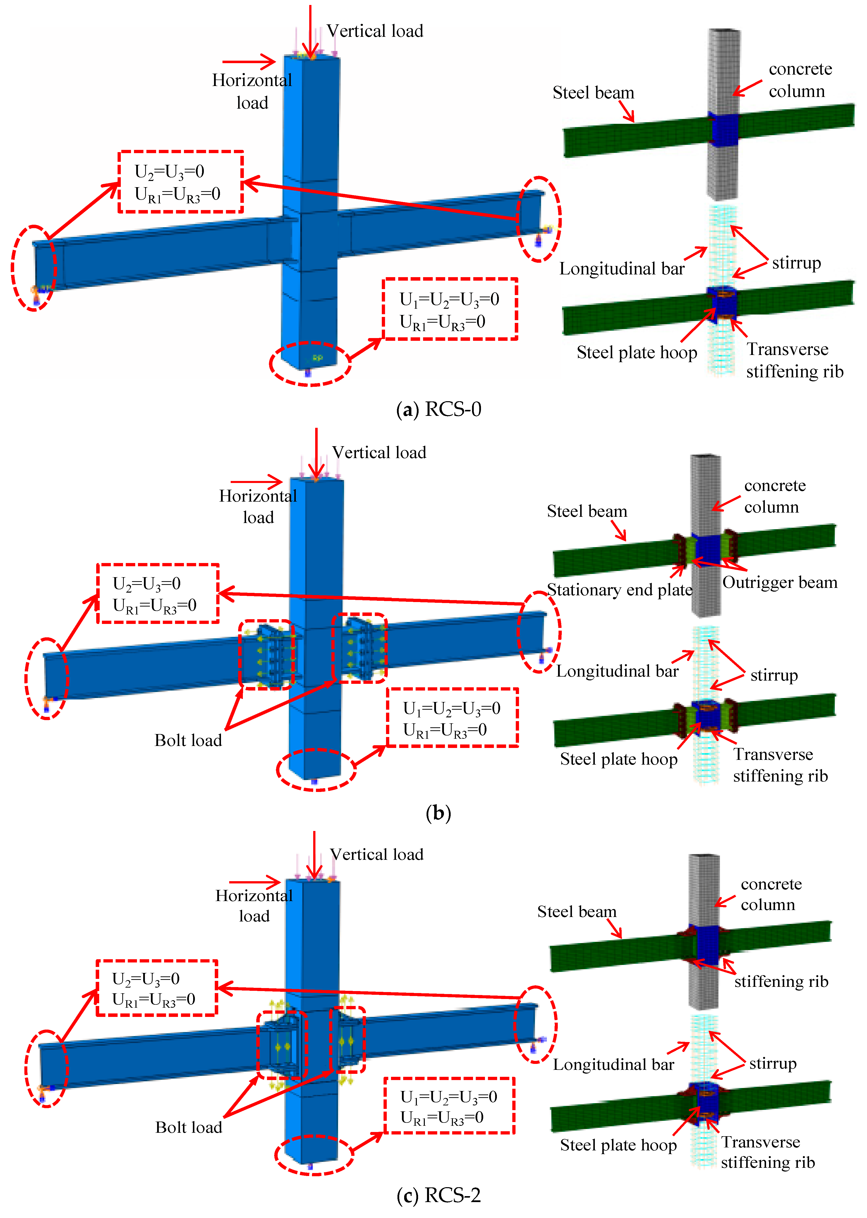
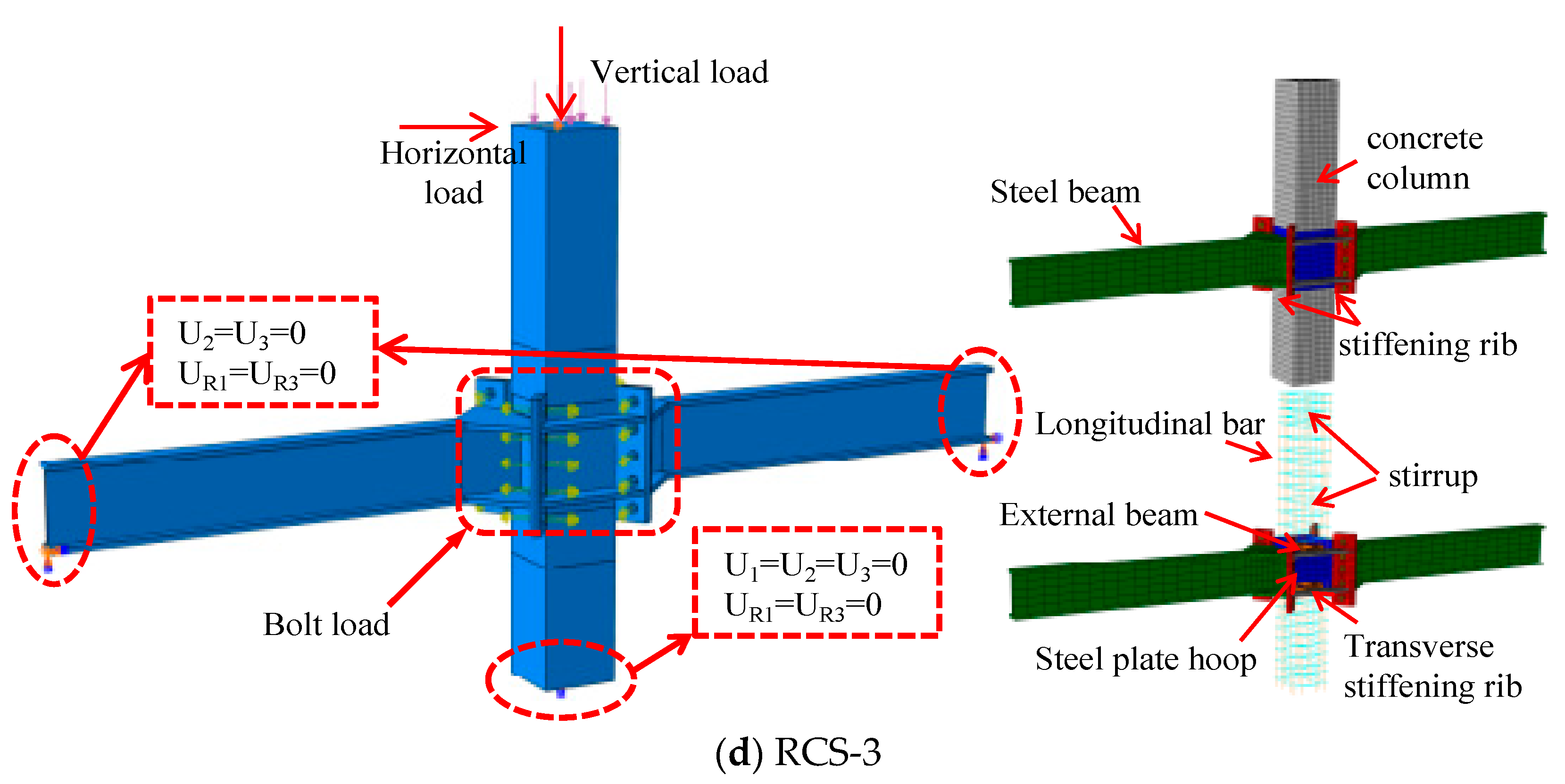
3.2. Model validation
3.2.1. Failure pattern
3.2.2. The hysteresis curves and skeleton curves
3.2.3. Ductility
3.2.4. Energy dissipation
4. FEM parameter analysis
4.1. Steel strength of some connector
4.2. Bolt strength
4.3. Steel beam flange thickness
5. Shear capacity analysis
6. Conclusions
- (1)
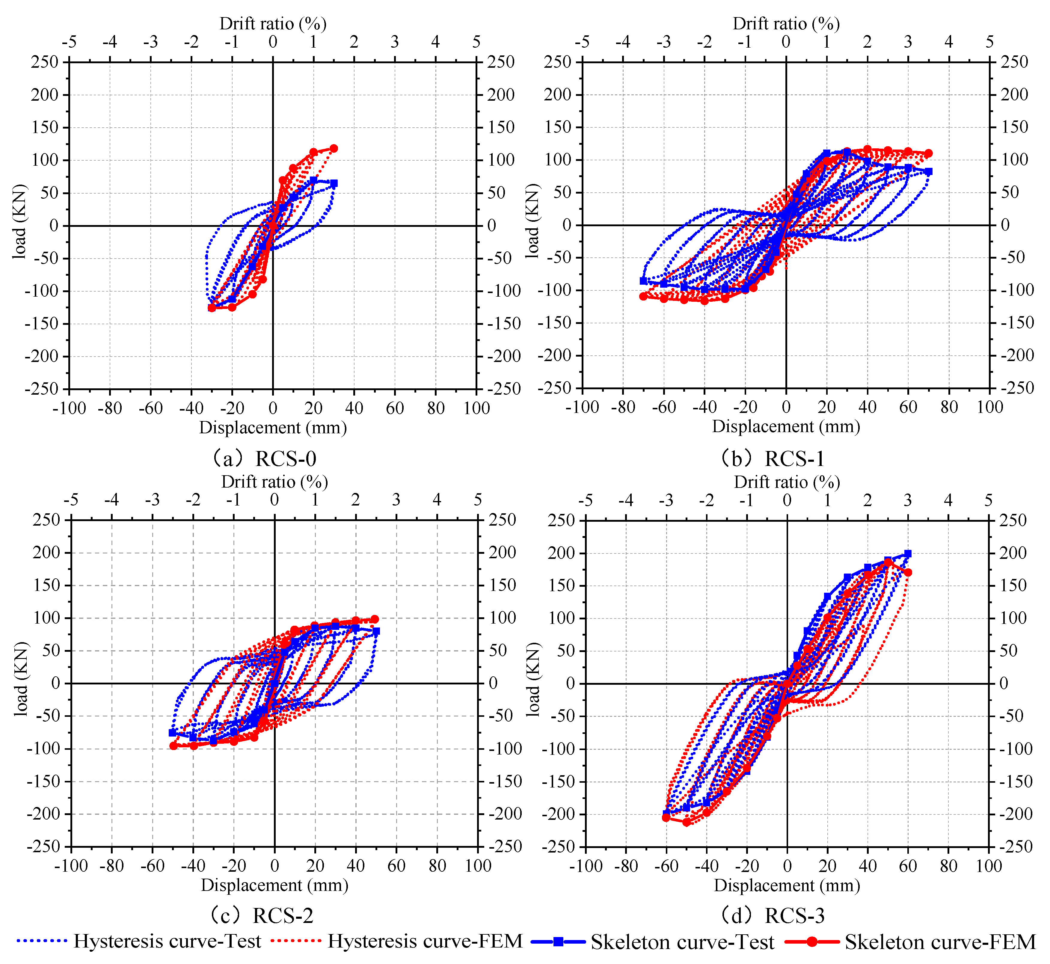
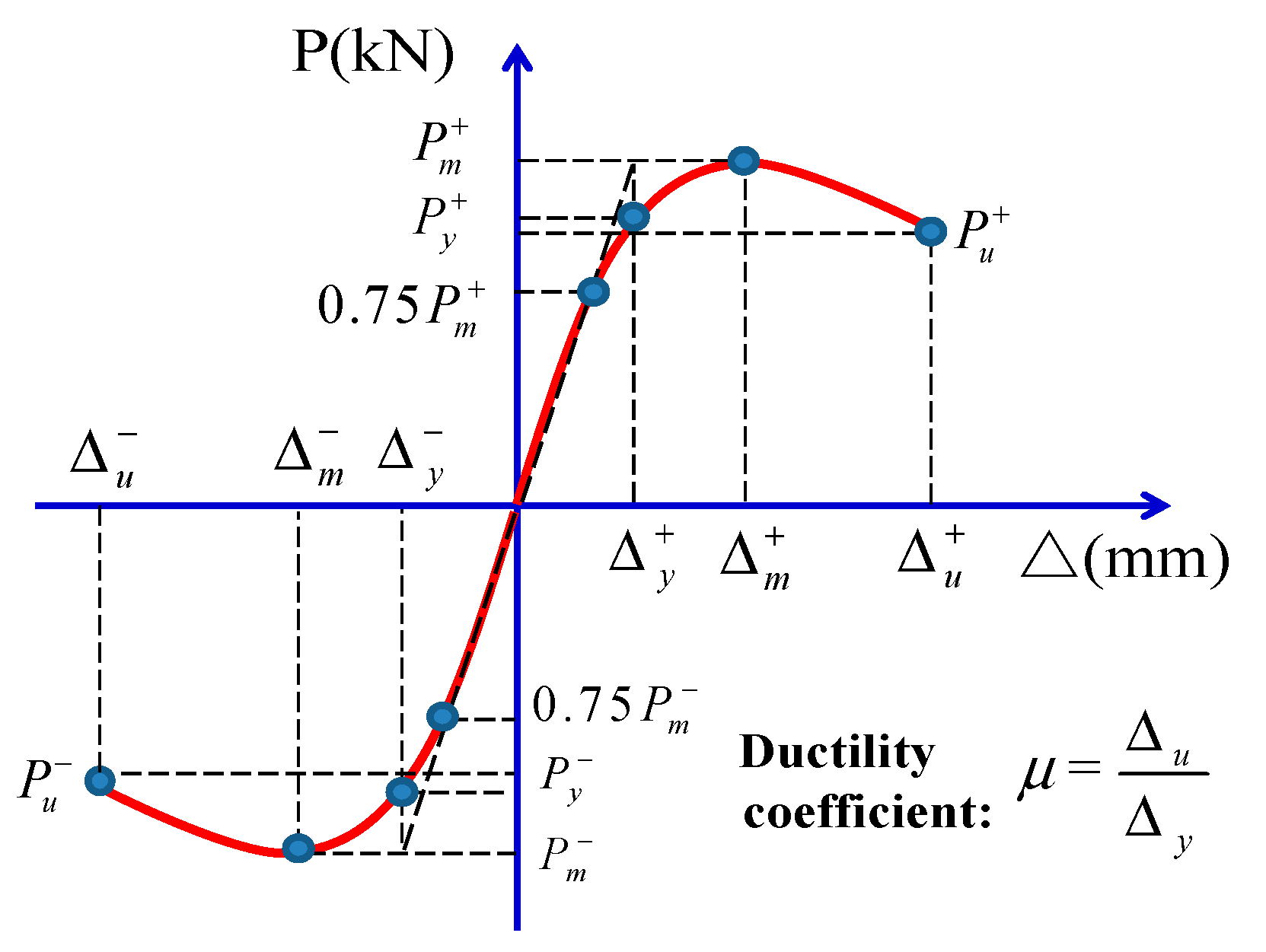
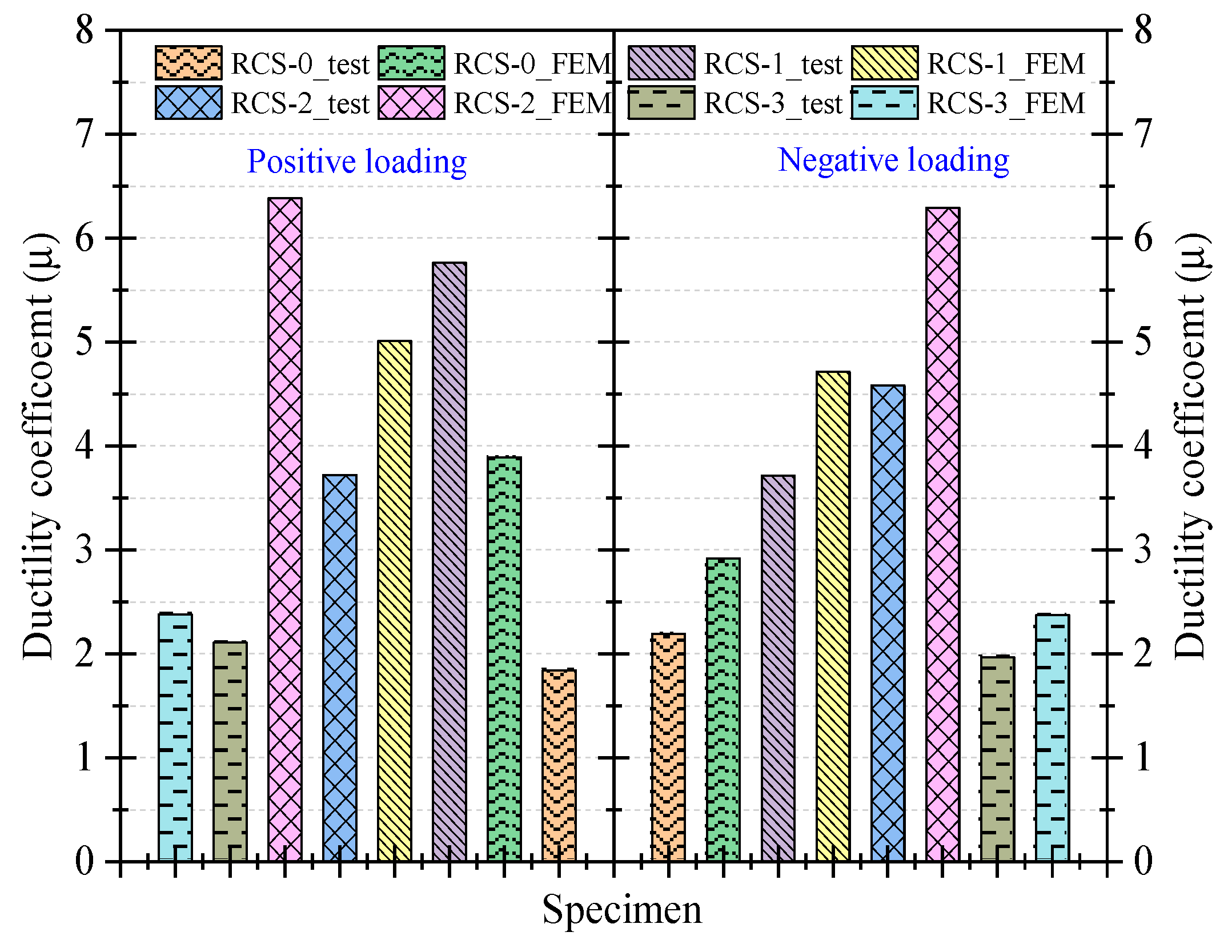
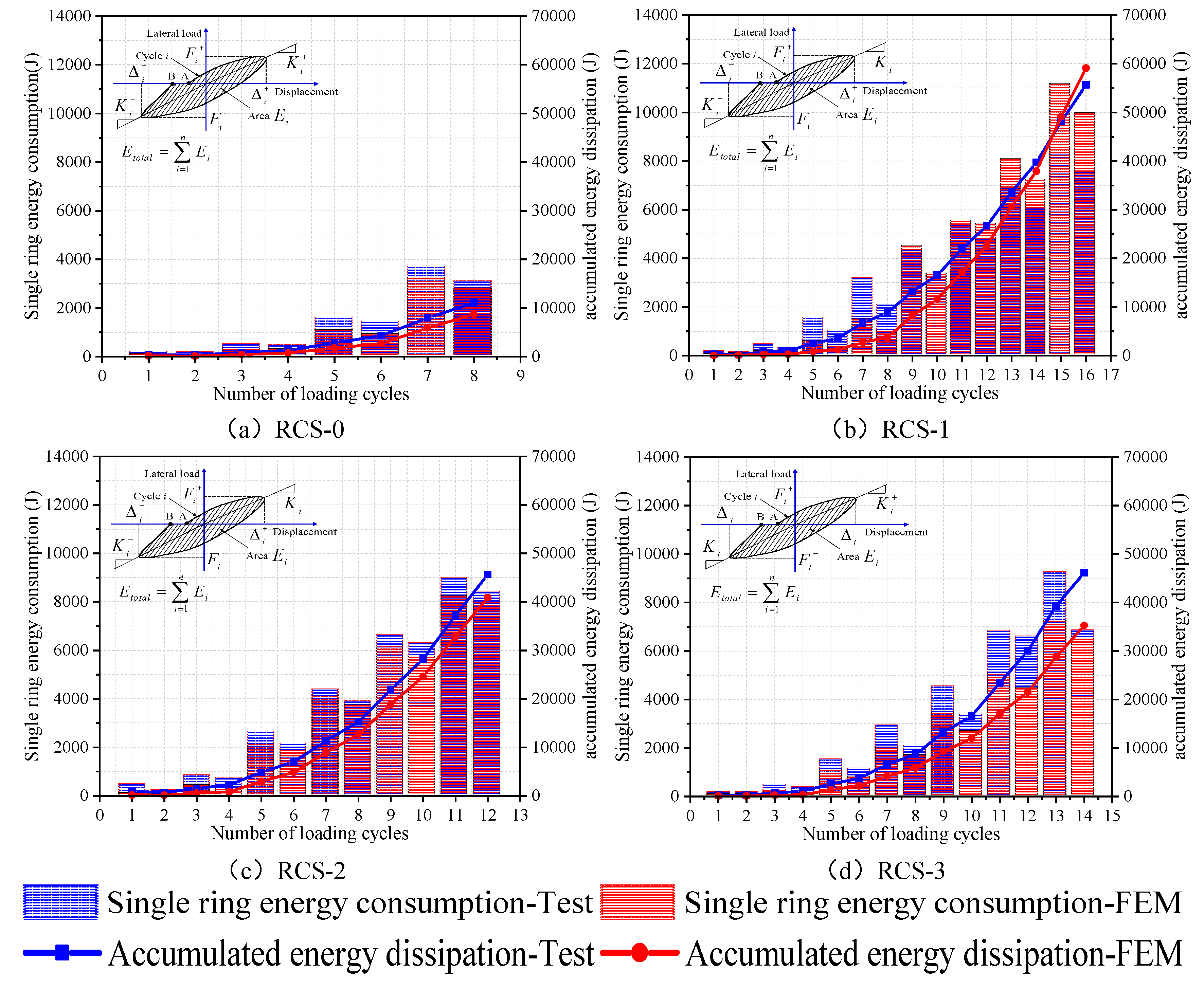
- From the experimental results, the bearing capacity and seismic performance of the three new demountable RCS joints are superior to the control group of non-demountable RCS joints. The RCS-1 and RCS-2 specimens have better deformation capabilities than the RCS-0 specimen, with ductility coefficients increased by 69% and 109%, respectively, while the difference in deformation capability between the RCS-3 specimen and the RCS-0 specimen is not significant, with positive and negative loading direction ductility coefficients differing by 14.68% and 10.04%, respectively. The same trend is observed in the energy dissipation capacity of the joints, as the deformability of the joints determines the cumulative energy dissipation of the joints.
- (2)
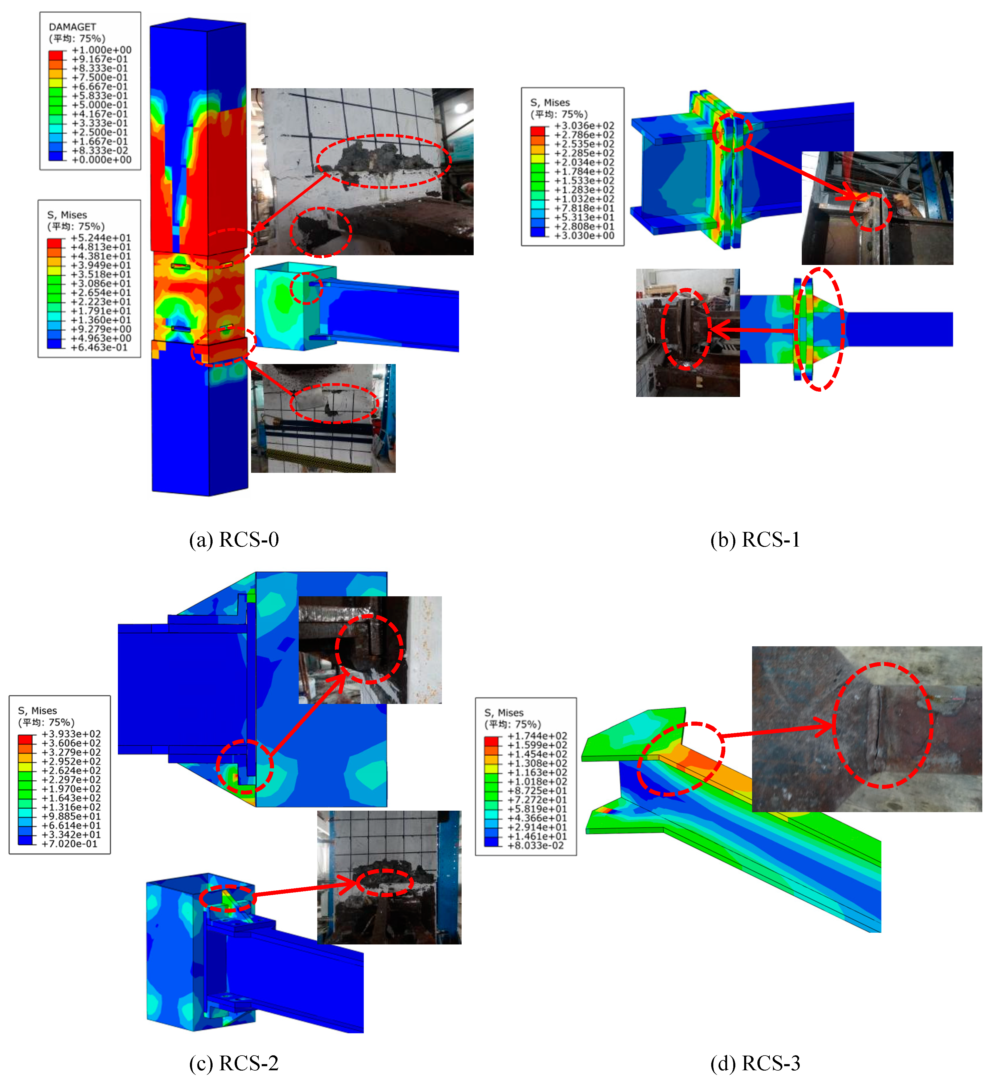
- The established finite element model can simulate the performance of non-demountable RCS joints (RCS-0) and demountable RCS joints (RCS-1, RCS-2, and RCS-3) under low cycle reciprocal loading. The finite element model can effectively reproduce the experimental results and meet the accuracy requirements in terms of joint failure mode, hysteresis behavior, ductility, and energy dissipation.
- (3)
- The finite element model validated by experimental results was further analyzed by parameter studies. The results showed that the hysteretic response of demountable joints RCS-1 and RCS-2 is not sensitive to the strength of the detailed connections, while the bolt strength has no significant influence on the hysteretic response of demountable joints RCS-1 and RCS-3.
- (4)
- The flange thickness of the steel beam has a significant effect on the bearing capacity of the demountable joints. As the flange thickness increases from 10 mm to 24 mm, the ultimate bearing capacity of each joint increases by 9.44%, 10.02%, and 8.24%, respectively. Compared with the skeleton curve, the cross-sectional design of the experimental steel beam is appropriate and can fully exert its flexural bearing capacity.
- (5)
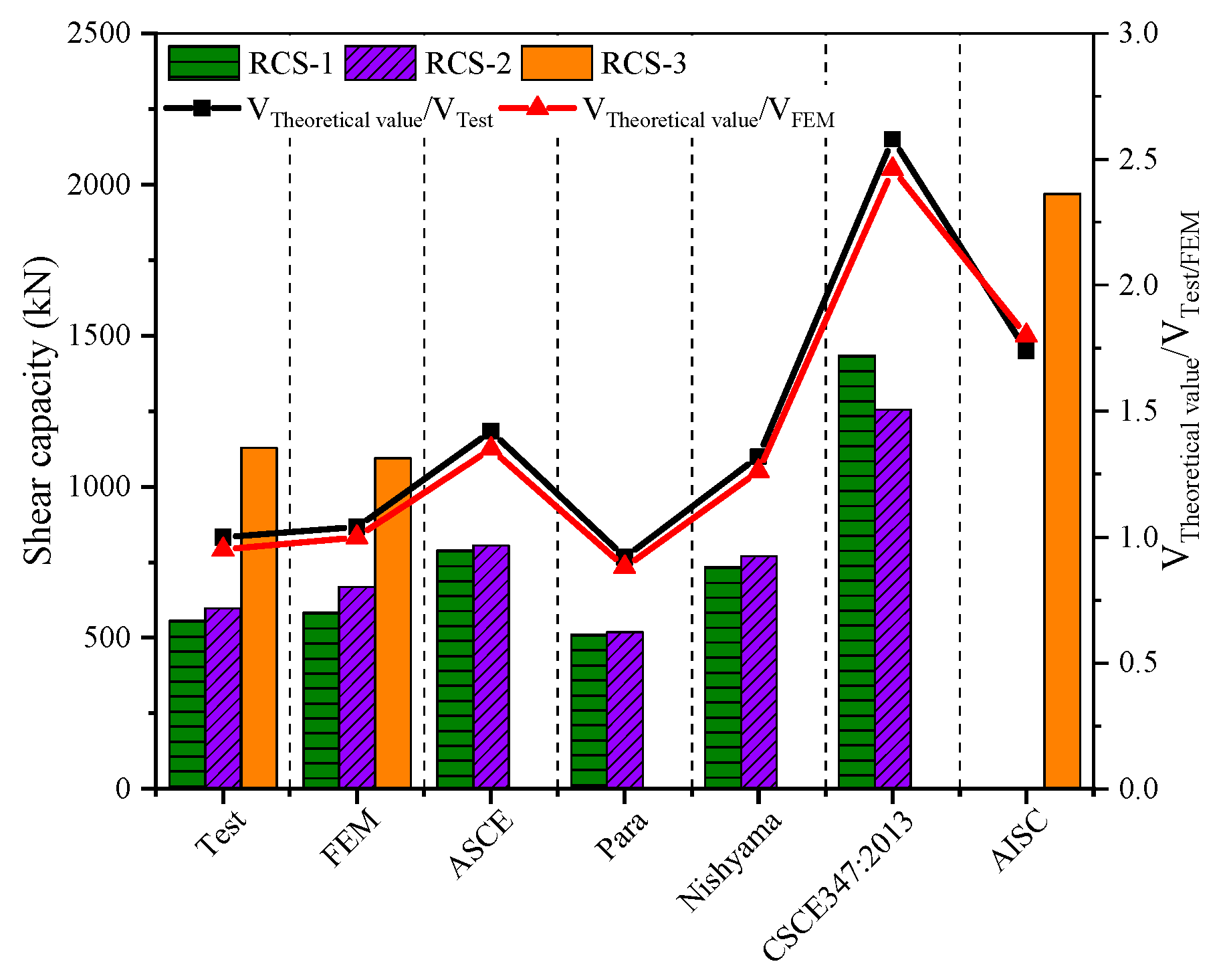
- This study refers to four different calculation methods recommended in the literature to check whether the shear capacity of the nodal core area meets the requirements. By comparing the theoretical calculation results with the experimental and FEM predicted values, it is found that the calculation results for RCS-1 and RCS-2 specimens are higher than the experimental and predicted values because the cylindrical steel plates in these specimens have not yielded. On the other hand, the Para method does not consider the contribution of the cylindrical steel plate to the shear strength of the joint core area, so the calculated result obtained from the formula is underestimated. For the RCS-3 specimen, a four-sided plate is added to the outer ring of the steel plate hoop according to the calculation requirements of ANSI/AISC 358-16, and the calculated shear capacity of the joint core area is overestimated.
Author Contributions
Funding
Institutional Review Board Statement
Informed Consent Statement
Data Availability Statement
Conflicts of Interest
References
- Figueira D, Ashour A, Yıldırım G, et al. Demountable connections of reinforced concrete structures: Review and future developments[C]//Structures. Elsevier, 2021, 34: 3028-3039.
- Yang Y, Chen B, Su Y, et al. Concrete mix design for completely recycled fine aggregate by modified packing density method[J]. Materials, 2020, 13(16): 3535.
- Yang Y, Chen B, Zeng W, et al. Utilization of completely recycled fine aggregate for preparation of lightweight concrete partition panels[J]. International Journal of Concrete Structures and Materials, 2021, 15: 1-11.
- Uy B, Patel V, Li D, et al. Behaviour and design of connections for demountable steel and composite structures[C]//Structures. Elsevier, 2017, 9: 1-12.
- Han D, Kalantari M, Rajabifard A. Building information modeling (BIM) for construction and demolition waste management in Australia: A research agenda[J]. Sustainability, 2021, 13(23): 12983.
- van den Berg M, C. Managing circular building projects[J]. 2019.
- Tingley D D, Davison B. Design for deconstruction and material reuse[J]. Proceedings of the institution of civil engineers-energy, 2011, 164(4): 195-204.
- Rakhshan K, Morel J C, Alaka H, et al. Components reuse in the building sector–A systematic review[J]. Waste Management & Research, 2020, 38(4): 347-370.
- Wang J, Uy B, Thai H T, et al. Behaviour and design of demountable beam-to-column composite bolted joints with extended end-plates[J]. Journal of Constructional Steel Research, 2018, 144: 221-235.
- Ataei A, Bradford M A, Valipour H R. Experimental study of flush end plate beam-to-CFST column composite joints with deconstructable bolted shear connectors[J]. Engineering structures, 2015, 99: 616-630.
- Ataei A, Bradford M A, Valipour H R, et al. Experimental study of sustainable high strength steel flush end plate beam-to-column composite joints with deconstructable bolted shear connectors[J]. Engineering Structures, 2016, 123: 124-140.
- Peng L, F. Study on Hysteretic Behavior of a New Prefabricated Concrete Filled Square Steel Column-Steel Beam Joint,PhD dissertation, 2020.
- Xiao J, Ding T, Zhang Q. Structural behavior of a new moment-resisting DfD concrete connection[J]. Engineering Structures, 2017, 132: 1-13.
- Ding T, Xiao J, Chen E, et al. Experimental study of the seismic performance of concrete beam-column frame joints with DfD connections[J]. Journal of Structural Engineering, 2020, 146(4): 04020036.
- Huang W, Hu G, Miao X, et al. Seismic performance analysis of a novel demountable precast concrete beam-column connection with multi-slit devices[J]. Journal of Building Engineering, 2021, 44: 102663.
- Wang W, Zhang X D, Chen J, et al. Repetitive behavior of an advanced demountable bolted shear connection in push-off tests[J]. Construction and Building Materials, 2023, 362: 129656.
- Malla P, Xiong F, Cai G, et al. Numerical study on the behaviour of vertical bolted joints for precast concrete wall-based low-rise buildings[J]. Journal of Building Engineering, 2021, 33: 101529.
- He J, Suwaed A S H, Vasdravellis G, et al. Behaviour and design of the ‘lockbolt’demountable shear connector for sustainable steel-concrete structures[C]//Structures. Elsevier, 2022, 44: 988-1010.
- Loqman N, Safiee N A, Bakar N A, et al. Structural behavior of steel-concrete composite beam using bolted shear connectors: A review[C]//MATEC Web of Conferences. EDP Sciences, 2018, 203: 06010.
- Cheng C T, Chen C C. Seismic behavior of steel beam and reinforced concrete column connections[J]. Journal of constructional steel research, 2005, 61(5): 587-606.
- Dung Le D, Nguyen X H, Nguyen Q H. Cyclic testing of a composite joint between a reinforced concrete column and a steel beam[J]. Applied Sciences, 2020, 10(7): 2385.
- Zhang J, Hu X, Gong S, et al. Experimental investigation of steel-concrete composite beam to reinforced-concrete column joints with single plate shear connection[J]. Engineering Structures, 2021, 245: 112906.
- Fargier-Gabaldón L B, Parra-Montesinos G J, Wight J K. Seismic Behavior of Exterior Reinforced Concrete Wide-Column-to-Steel Beam Joints[J]. ACI Structural Journal, 2020, 117(2): 117-128.
- Men J, Xiong L, Wang J, et al. Effect of different RC slab widths on the behavior of reinforced concrete column and steel beam-slab subassemblies[J]. Engineering Structures, 2021, 229: 111639.
- Huang S-M, Wang Y-Y, Ding J-M, et al. National standard of the People's Republic of China.GB 50011-2010 Code for seismic design of buildings [S]. Beijing: China Construction Industry Press, 2010.
- Gao Yifei, Liang Xinbang, Dong Li, et al. National standard of the People's Republic of China.GB/T 228.1-2010 Tensile testing of metallic materials Part I: Room temperature test methods [S]. Beijing: China Construction Industry Press, 2010.
- Cheng Shaoge, Shi Tihua, Bai Xueshuang et al. National standard of the People's Republic of China. jgj/t 101-2015 specification for seismic testing of buildings [S]. Beijing: China Construction Industry Press, 2015.
- Zhao Kida, Xu Youyi, Huang Xiaokun et al. National standard of the People's Republic of China.GB 50010-2010 Design code for concrete structures [S]. Beijing: China Construction Industry Press, 2010.
- TAO Yuchen, XIAO Zhibin, ZHAO Weijian.Comparative study on calculation methods of shear capacity of RCS hybrid joints[J/OL]. Journal of Harbin Institute of Technology:1-16.
- P. Cordova, Validation of the Seismic Performance of Composite RCS Frames: Full-Scale Testing Analysis and Seismic Design, Stanford University, USA, 2005.PhD dissertation.
- H.W. Ma, Study on the Joints of Composite Beam and Continuous Compound Spiral Hoop Reinforced Concrete Column, PhD dissertation, Xi’an University of architecture and technology, Xi’an, P.R. China, 2003 [in Chinese].
- Parra-Montesinos G, Wight J K. Modeling shear behavior of hybrid RCS beam-column connections[J]. Journal of structural engineering, 2001, 127(1): 3-11.
- Nishiyama I, Kuramoto H, Noguchi H. Guidelines: seismic design of composite reinforced concrete and steel buildings[J]. Journal of structural engineering, 2004, 130(2): 336-342.
- Jiang Weishan, Yu Qingrong, Pan Shubin, et al. National Standard of the People's Republic of China.CECS 347-2013 Technical Specification for Constrained Concrete Column Combined Beam Frame Structures [S]. Beijing: China Construction Industry Press, 2013.
- AISC, Prequalified Connections for Special and Intermediate Steel Moment Frames for Seismic Applications, AISC, Chicago, 2016. ANSI/AISC 358-16.


| Grade | Sampling position | /GPa | ||||
|---|---|---|---|---|---|---|
| Q235 | Web and cover plate | 198 | 308.3 | 0.00206 | 450.5 | 0.1598 |
| Flange and side plate | 205 | 254.5 | 0.00217 | 423.2 | 0.1612 | |
| HRB400 | Longitudinal bar | 196 | 479.3 | 0.00213 | 631.2 | 0.1532 |
| HPB300 | Stirrup | 201 | 342.7 | 0.00221 | 487.6 | 0.1956 |
| 8.8 | Bolts | 200 | 780 | 0.00202 | 900 | 0.1360 |
| Specimen ID | RCS-0 | RCS-1 | RCS-2 | RCS-3 | ||||||
|---|---|---|---|---|---|---|---|---|---|---|
| Average compressive strength(MPa) | 38.50 | 42.52 | 30.95 | 39.24 | ||||||
| V2b | −787.1 | −797.0 | −620.2 | −380.7 | 1.01 | 0.30 | ||||
| Specimen ID | Load direction | Yield load | Yield displacement | Peak load | Peak displacement | Ductility coefficient | |
|---|---|---|---|---|---|---|---|
| Test | RCS-0 | Negative | -94.20 | -16.28 | -125.6 | -30.00 | 1.84 |
| Positive | 52.31 | 13.68 | 69.75 | 30.00 | 2.19 | ||
| RCS-1 | Negative | -74.00 | -12.15 | -98.66 | -70.00 | 5.76 | |
| Positive | 83.93 | 11.67 | 111.9 | 43.29 | 3.71 | ||
| RCS-2 | Negative | -65.64 | -13.44 | -87.52 | -50.00 | 3.72 | |
| Positive | 65.76 | 10.92 | 87.68 | 50.00 | 4.58 | ||
| RCS-3 | Negative | -159.00 | -28.37 | -212 | -60.00 | 2.11 | |
| Positive | 139.36 | 30.46 | 185.81 | 60.00 | 1.97 | ||
| FEM | RCS-0 | Negative | -94.23 | -7.71 | -125.64 | -30.00 | 3.89 |
| Positive | 88.58 | 10.29 | 118.10 | 30.00 | 2.92 | ||
| RCS-1 | Negative | -87.04 | -13.98 | -116.06 | -70.00 | 5.01 | |
| Positive | 87.23 | 14.86 | 116.31 | 70.00 | 4.71 | ||
| RCS-2 | Negative | -71.64 | -7.84 | -95.52 | -50.00 | 6.38 | |
| Positive | 73.64 | 7.95 | 95.19 | 50.00 | 6.29 | ||
| RCS-3 | Negative | -149.30 | -25.22 | -199.06 | -60.00 | 2.38 | |
| Positive | 149.51 | 25.31 | 199.34 | 60.00 | 2.37 |
| Joint types | RCS-1 | RCS-2 | RCS-3 | |
|---|---|---|---|---|
| Test values | 555.48 | 596.21 | 1128.32 | |
| FEM | 583.25 | 667.76 | 1094.47 | |
| ASCE | 788.78 | 804.88 | - | |
| 1.42 | 1.30 | |||
| 1.35 | 1.21 | |||
| Para | 511.04 | 518.70 | ||
| 0.92 | 0.87 | |||
| 0.88 | 0.78 | |||
| 733.23 | 769.11 | |||
| 1.32 | 1.29 | |||
| 1.26 | 1.15 | |||
| CSCE 347:2013 | 1433.29 | 1254.84 | ||
| 2.58 | 2.10 | |||
| 2.46 | 1.88 | |||
| AISC | - | 1967.88 | ||
| 1.74 | ||||
| 1.80 | ||||
Disclaimer/Publisher’s Note: The statements, opinions and data contained in all publications are solely those of the individual author(s) and contributor(s) and not of MDPI and/or the editor(s). MDPI and/or the editor(s) disclaim responsibility for any injury to people or property resulting from any ideas, methods, instructions, or products referred to in the content. |
© 2023 by the authors. Licensee MDPI, Basel, Switzerland. This article is an open access article distributed under the terms and conditions of the Creative Commons Attribution (CC BY) license (http://creativecommons.org/licenses/by/4.0/).


