1. Introduction
Although the rapid growth of microwave technology
has brought about scientific and technological prosperity, it has also led to
EM pollution [1]. EM absorption materials
substantially reduce the energy of EM projected onto their surface. They are
widely used in electrical equipment, military equipment stealth, and individual
protection [2,3]. The materials are coated
with an absorbing layer to reduce the reflection of EM microwaves, thereby
avoiding radar detection for important military purposes. With the
diversification of practical use environments, structural and functional
integration materials are used for preparing EM absorption materials due to
their excellent comprehensive performance [4–6].
Carbon materials have always played a crucial role
in the field of EM shielding [7–9]. In recent
years, there has been extensive research on the absorption properties of
graphite oxide (GO) [10,11], carbon fiber [12], and carbon nanotubes (CNTs) [13,14]. GO has garnered significant attention among
these materials as a potentially efficient EM shielding material. Li et al. [15] conducted a study on the influence of the
doping amount of GO on the crystal structure, surface morphology, and magnetic
properties of composite EM absorption materials. Their findings shed light on
the potential for enhancing the absorption properties by adjusting the doping
amount. Zhan et al. [16] developed
sandwich-like graphene nanosheet/Fe3O4 composites using a one-step solvent thermal
method. These composites exhibited high saturation magnetization and
proclivity, as well as high complex dielectric constant and complex
permeability. Moreover, Xu et al. [17]
reported that the high density of residual defects and functional groups attached
to reduced GO can greatly improve the absorption performance of the material.
These works highlight the importance of carbon-based materials, particularly
GO, in the development of efficient EM shielding materials. Further research in
this area will contribute to the advancement of EM absorption materials and
their practical applications.
Simultaneous consideration of reflectivity and
transmissivity is crucial when evaluating the performance of EM absorption
materials [18–20]. This necessitates the
constant improvement of evaluation and testing methods to provide a basis for
assessing their development and application. The Cellular Telecommunications
Industry Association (CTIA) has developed relevant standards for Over the Air
(OTA) testing. OTA testing primarily focuses on assessing the radiation
performance of the entire device and has gained recognition as an important
test for mobile phone manufacturers. Line gain, which represents the ratio of
power density generated by the actual antenna to the ideal radiation unit at
the same point in space under equal input power conditions, is used to evaluate
the gain of an antenna. The gain is closely related to the antenna's radiation
pattern, with a narrower main lobe, smaller side lobes, and higher gain indicating
better performance. Antenna efficiency, on the other hand, is defined as the
ratio of radiated power to input power. In this work, a comparison test of
efficiency and gain was conducted using domestically developed OTA darkroom EM
absorption materials. This method provides a means of assessing the
effectiveness of the materials in terms of efficiency and gain.
2. Experiment Section
2.1. Synthesis of EM absorption film
The hydrophilic graphene and hydrophilic
single-walled carbon nanotubes (CNTs) were dissolved in deionized (DI) water at
a mass ratio of 3:2. The total mass of graphene and single-walled CNTs ranged
from 0.5 wt% to 1.5 wt% of the mass of DI water. The resulting solution was
subjected to ultrasonic treatment for 6 to 14 hours. Subsequently, the mixture
was added to a polyethylene solution with a mass concentration of 5% to 15%.
The mixture was stirred for 2 to 3 hours and then dried for 48 hours to obtain the
absorption film. This film exhibited absorption performance and had a certain
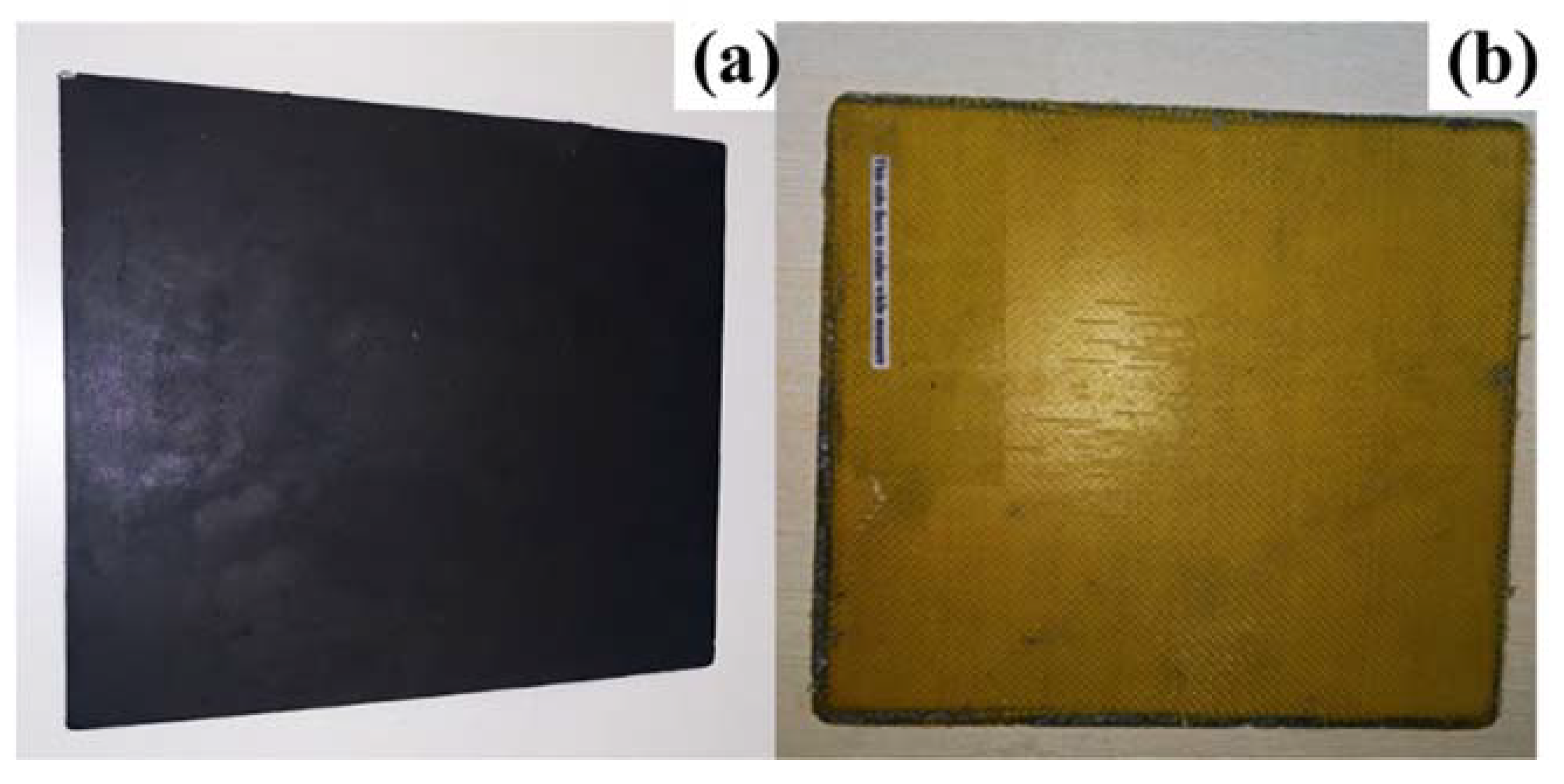
level of tenacity. For testing purposes, the size of the film used was 25 cm×30
cm, as shown in
Figure 1a. The absorption
film was placed into the interlayer of yellow fiber material To evaluate the
actual application of the absorption, as shown in
Figure 1b.
2.2. Test procedure
The receiving antenna is a standard horn antenna
whose frequency is from 600 MHz to 6 GHz. Antenna 2 which is designed and
manufactured by the Suzhou NQI used in Italy Electric Power Company Router. An
Agilent vector network analyzer (VNA 8753ES) in the frequency range of 100KHz
to 6 GHz is employed to measure the S-parameters, covering the frequency band
of GSM/CDMA2000/WCDMA/LTE.
One way of the traditional test process is the |S21|
EM absorption film test process. We use the VNA in an anechoic chamber to
analyze the performance of EM absorption film. The following is the detail. At
first, the transmitting antenna was measured and confirmed. The measurement
specification is shown in Tables 1 and 2.
Table 1.
Electrical parameters.
Table 1.
Electrical parameters.
| Frequency Range |
824-960MHz/1710-1880 MHz /1920-2170MHz |
| VSWR |
GSM-ETACS-NMT≤2.2/PCN-GSM≤2.2/UMTS≤2.2 |
| Characteristic impedance (Ω) |
50 |
| Minimum gain (dB) |
2 |
| Polarization mode |
Vertical |
| Maximum power (W) |
10 |
Table 2.
Mechanical parameters.
Table 2.
Mechanical parameters.
| Antenna Dimensions (mm) |
114.8*10 |
| Connector |
SMA |
| Working temperature (℃) |
Operating: -40 ~ 75 |
| Storage temperature (℃) |
Storage: -40 ~ 85 |
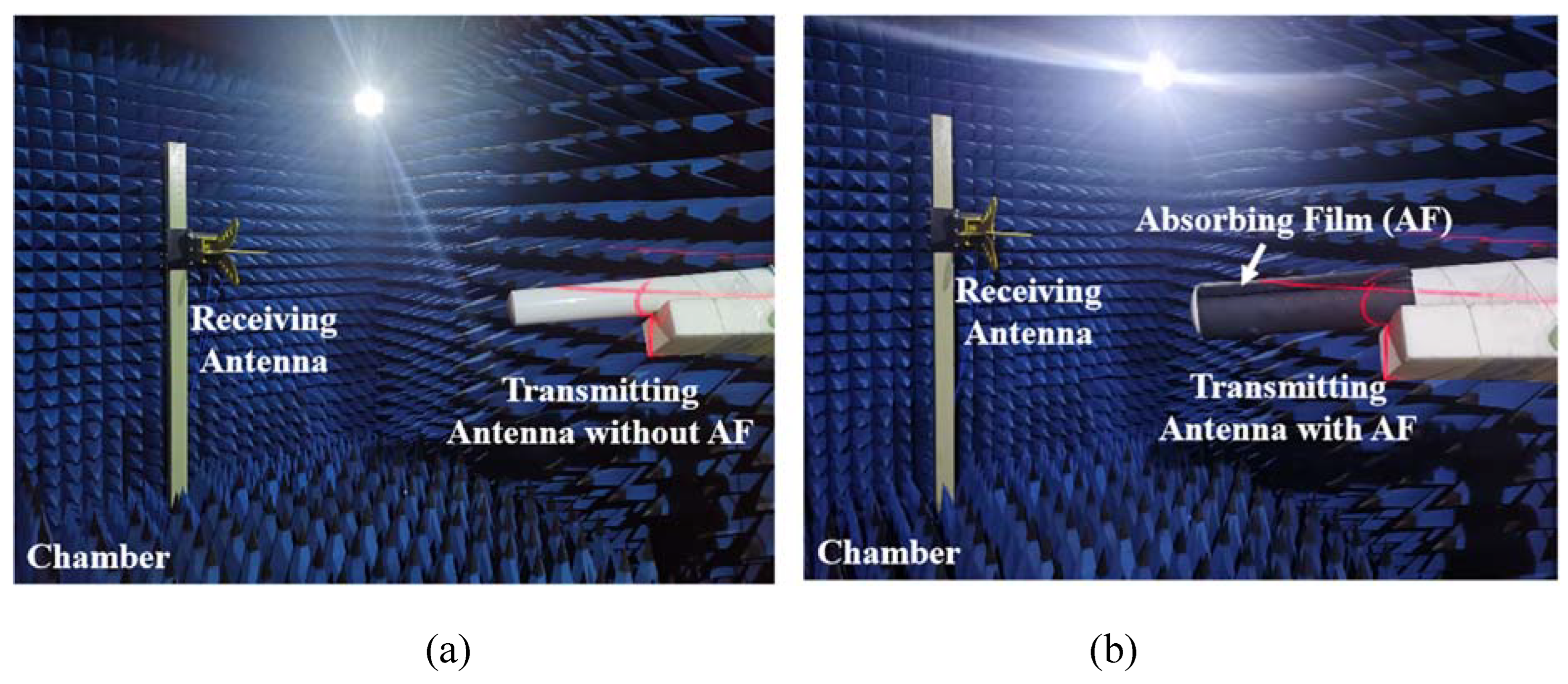
The block diagram of the test schematic is shown in
Figure 2. Each component of the mainframe was connected, and the system was preheated for half an hour after booting before testing. The experiment setup involved using Antenna 1 as the receiving antenna and Antenna 2 as the transmitting antenna, based on the structure and size of the chamber. The efficiency and gain measured results of Antenna 2 were compared with and without the absorption material. Inside the chamber, the arrangement is depicted in
Figure 2. The transmitting antenna is completely wrapped inside by absorbing material. The test was carried out in two radiation modes: without the absorption material (see
Figure 2a) and with the absorption material (see
Figure 2b). Data was collected during the test and plotted for analysis.
3. Results and Discussions
The antenna performance testing can be divided into passive testing and active testing, with OTA testing falling under the category of active testing. The Total Radiated Power (TRP) is obtained by integrating and averaging the transmitting power of the fully radiating sphere, which reflects the transmitting power of the entire device. The Total Isotropic Sensitivity (TIS) reflects the sensitivity index of the fully radiating sphere, which is related to the overall machine's conduction sensitivity and the antenna's radiation performance. The actual performance indicators of the transmitting antenna are installed on the router. These indicators provide information about the tested performance of the transmitting antenna.
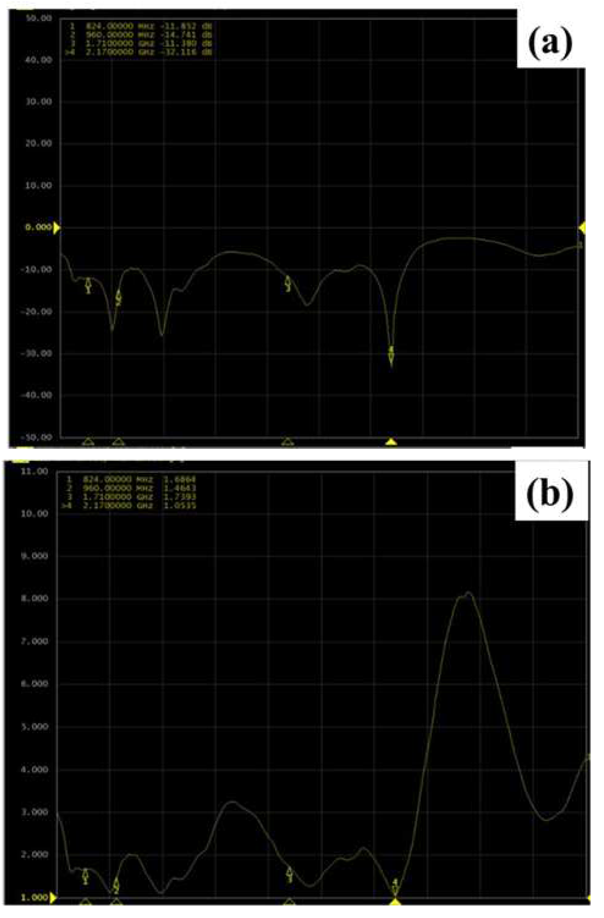
Figure 3 exhibits the scattering parameter return loss (RL) and Voltage standing wave ratio (VSWR) of the. VSWR refers to the ratio of standing wave belly voltage to wave valley voltage amplitude, which is used to indicate whether the antenna matches the radio station. The relationship between VSWR and RL is shown in Equations (1) and (2).
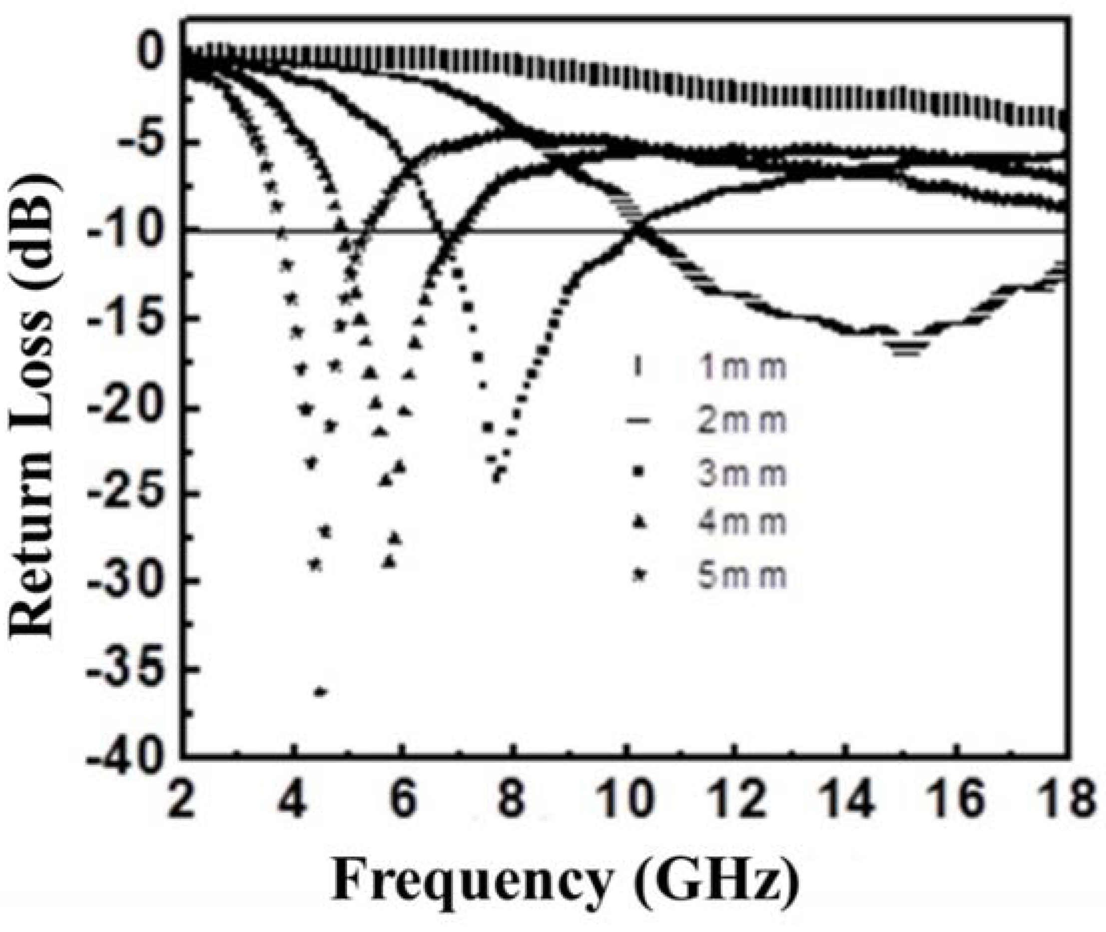
As depicted in
Figure 4, the EM absorption film exhibits a minimum Return Loss (RL) value of approximately 36 dB at a frequency of around 4.5 GHz when the film thickness is 5 mm. However, the corresponding bandwidth with effective attenuation (RL < -10 dB) is widest at a thickness of 2 mm. For the experimental needs of this work, a thickness of 2 mm is chosen for the absorption film in this work.
Comparing
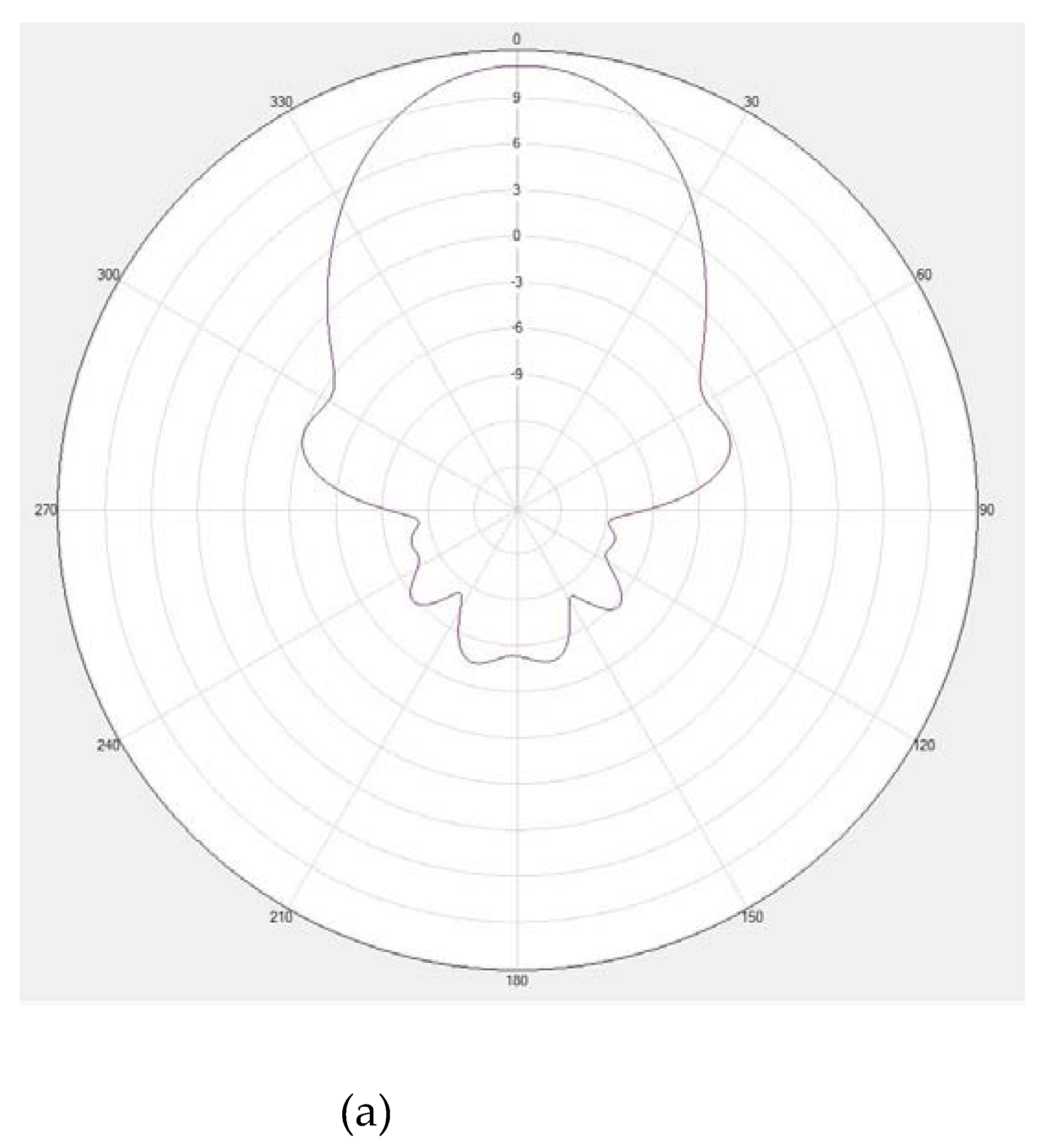
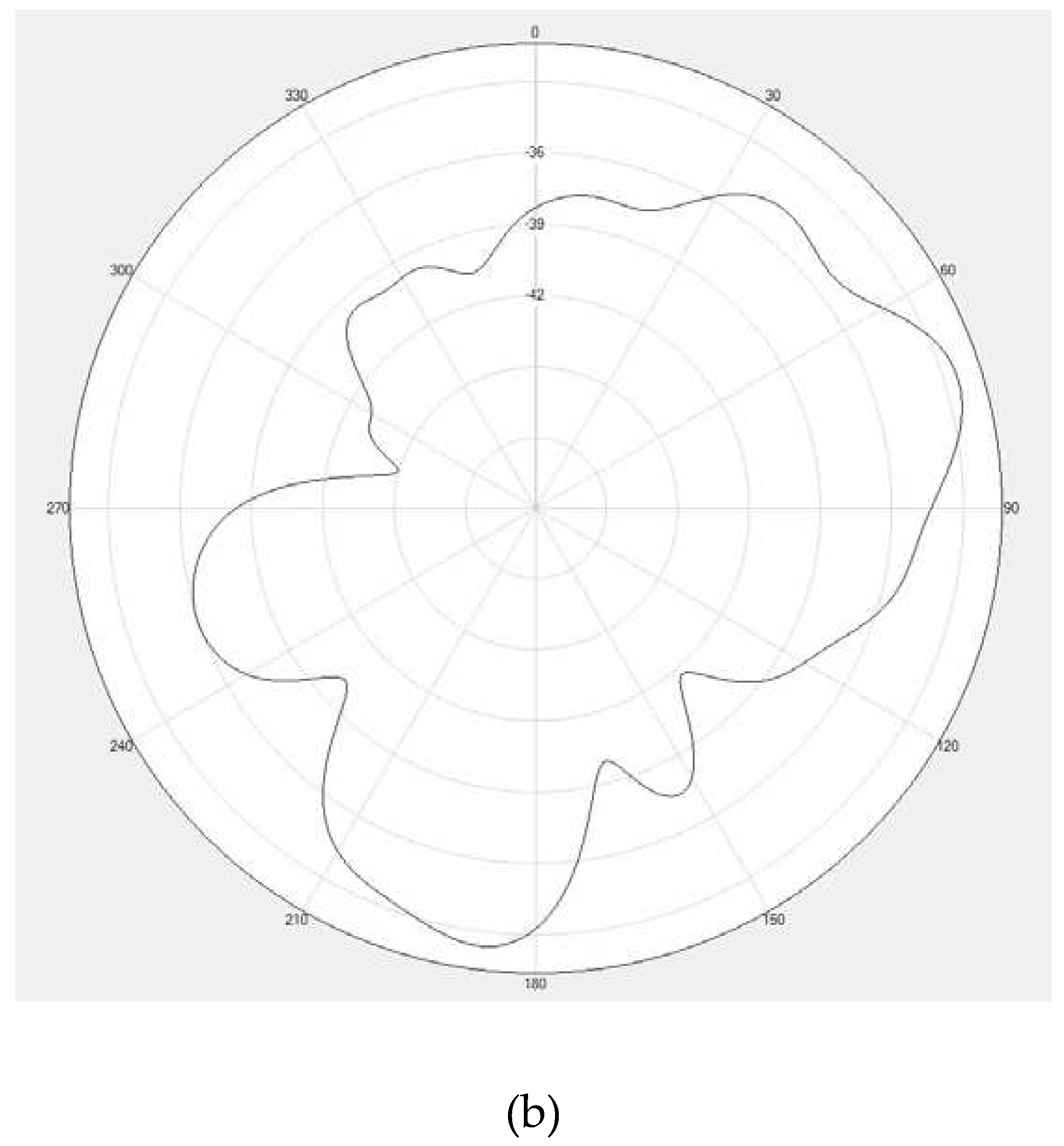
Figure 5a,b, it can be observed that the addition of the absorption material leads to a deterioration in the radiation pattern of the transmitting antenna in the direction where the absorption material is present, while there is a slight enhancement in the direction without the absorption material. This suggests that the absorption material significantly alters the antenna pattern of the transmitting antenna.
In
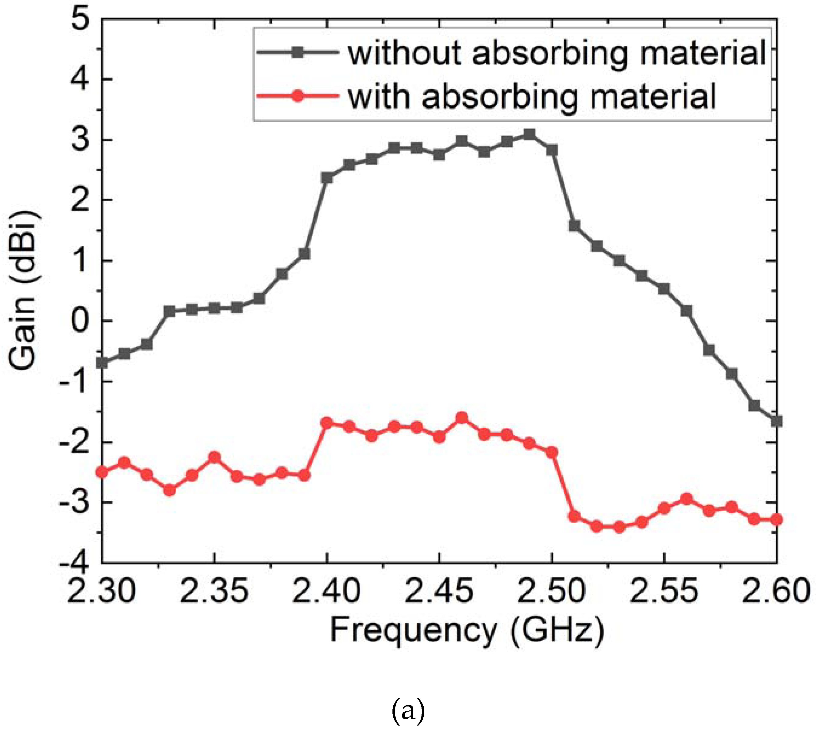
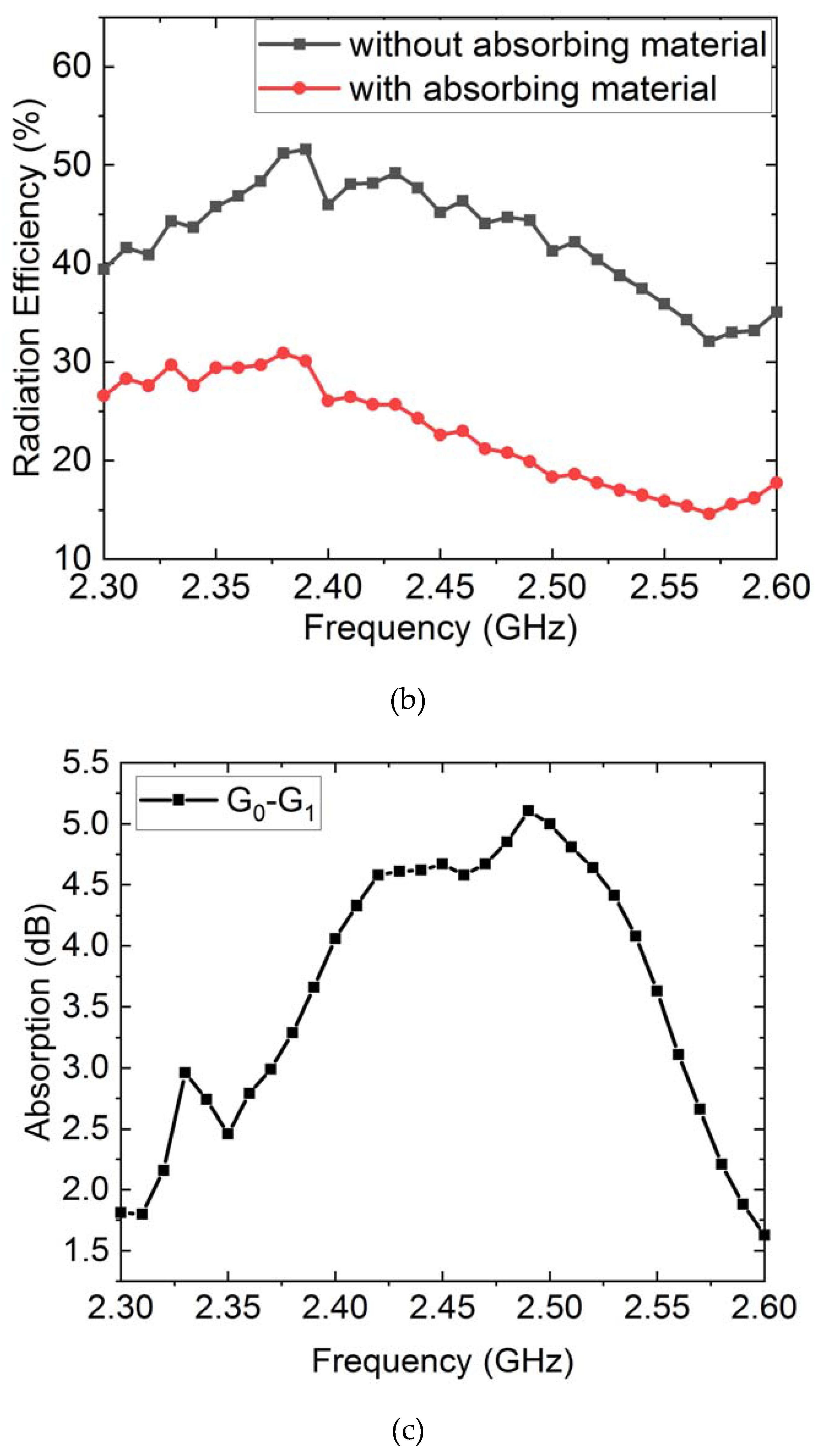
Figure 6a, it is evident that the absorption material has a noticeable impact on the antenna gain in the frequency range of 2300 MHz to 2600 MHz, resulting in a gain attenuation of approximately 3 dB. The comparison diagram of antenna efficiency change also shows that the absorption material has a significant absorption effect on the antenna efficiency in the same frequency range, absorbing about 15% of the efficiency performance.
4. Conclusion
In this paper, the EM absorption material was tested by comparing the antenna gain and efficiency of a wireless antenna. The test results of the standardized antenna led to the proposal of a new test method under the condition of incomplete shielding of the EM absorption material. This new test method provides a foundation for the use of absorption materials in various civil applications.
In the actual test results, it was observed that when the absorption material does not cover the entire surface of the objects (only covering one side), the performance of antenna gain dropped by 2-3 dB and efficiency decreased by more than 10% - 15%. However, it was also found that the gain and efficiency of some frequency bands and directional antennas increased. This finding highlights the significance of the new test method, as it allows for a better understanding of the practical properties of absorption materials in real-world applications.
Acknowledgements
This work was supported by the Fujian Key Laboratory of Advanced Manufacturing of Specialty Chemicals (Fuzhou University).
Conflicts of Interest
There are no conflicts to declare.
References
- L. Zou, S. Zhang, X. Li, C. Lan, Y. Qiu, Y. Ma, Step-by-Step Strategy for Constructing Multilayer Structured Coatings toward High-Efficiency Electromagnetic Interference Shielding, Advanced Materials Interfaces, 3 (2016) 1500476.
- X. Li, L. Wang, W. You, L. Xing, L. Yang, X. Yu, J. Zhang, Y. Li, R. Che, Enhanced polarization from flexible hierarchical MnO2 arrays on cotton cloth with excellent microwave absorption, Nanoscale, 11 (2019) 13269-13281. [CrossRef]
- L. Wang, X. Li, Q. Li, X. Yu, Y. Zhao, J. Zhang, M. Wang, R. Che, Oriented Polarization Tuning Broadband Absorption from Flexible Hierarchical ZnO Arrays Vertically Supported on Carbon Cloth, Small, 15 (2019) e1900900. [CrossRef]
- T. Zhu, S. Chang, Y.-F. Song, M. Lahoubi, W. Wang, PVP-encapsulated CoFe2O4/rGO composites with controllable electromagnetic wave absorption performance, Chemical Engineering Journal, 373 (2019) 755-766.
- T. Ergin, N. Stenger, P. Brenner, J.B. Pendry, M. Wegener, Three-Dimensional Invisibility Cloak at Optical Wavelengths, Science, 328 (2010) 337-339.
- J. Yan, Y. Huang, Y. Yan, L. Ding, P. Liu, High-Performance Electromagnetic Wave Absorbers Based on Two Kinds of Nickel-Based MOF-Derived Ni@C Microspheres, ACS applied materials & interfaces, 11 (2019) 40781-40792. [CrossRef]
- S. Gupta, N.-H. Tai, Carbon materials and their composites for electromagnetic interference shielding effectiveness in X-band, Carbon, 152 (2019) 159-187.
- Z. Jia, D. Lan, K. Lin, M. Qin, K. Kou, G. Wu, H. Wu, Progress in low-frequency microwave absorbing materials, Journal of Materials Science: Materials in Electronics, 29 (2018) 17122-17136. [CrossRef]
- Y. Zhu, S. Murali, W. Cai, X. Li, J.W. Suk, J.R. Potts, R.S. Ruoff, Graphene and graphene oxide: synthesis, properties, and applications, Advanced Materials, 22 (2010) 3906-3924.
- T. Kim, J. Lee, K. Lee, B. Park, B.M. Jung, S.B. Lee, Magnetic and dispersible FeCoNi-graphene film produced without heat treatment for electromagnetic wave absorption, Chemical Engineering Journal, 361 (2019) 1182-1189.
- P. Liu, S. Gao, Y. Wang, Y. Huang, Y. Wang, J. Luo, Core-Shell CoNi@Graphitic Carbon Decorated on B, N-Codoped Hollow Carbon Polyhedrons toward Lightweight and High-Efficiency Microwave Attenuation, ACS applied materials & interfaces, 11 (2019) 25624-25635. [CrossRef]
- Y. Liu, Z. Zhang, S. Xiao, C. Qiang, L. Tian, J. Xu, Preparation and properties of cobalt oxides coated carbon fibers as microwave-absorbing materials, Applied Surface Science, 257 (2011) 7678-7683. [CrossRef]
- M. Ning, J. Li, B. Kuang, C. Wang, D. Su, Y. Zhao, H. Jin, M. Cao, One-step fabrication of N-doped CNTs encapsulating M nanoparticles (M = Fe, Co, Ni) for efficient microwave absorption, Applied Surface Science, 447 (2018) 244-253.
- R. Shu, G. Zhang, X. Wang, X. Gao, M. Wang, Y. Gan, J. Shi, J. He, Fabrication of 3D net-like MWCNTs/ZnFe2O4 hybrid composites as high-performance electromagnetic wave absorbers, Chemical Engineering Journal, 337 (2018) 242-255. [CrossRef]
- M. Li, Preparation and properties of M-type barium ferrite/Go absorbing materials, Tianjin University, 2012.
- Y. Zhan, N. Yan, Y. Li, Y. Meng, J. Wang, N. Zhang, Q. Yu, H. Xia, Fabrication of graphene millimeter-vortex ring with excellent absorption via solution dripping and in-situ reduction method, Chemical Engineering Journal, 327 (2017) 142-149. [CrossRef]
- H. Xu, X. Yin, M. Li, X. Li, X. Li, X. Dang, L. Zhang, L. Cheng, Ultralight Cellular Foam from Cellulose Nanofiber/Carbon Nanotube Self-Assemblies for Ultrabroad-Band Microwave Absorption, ACS applied materials & interfaces, 11 (2019) 22628-22636. [CrossRef]
- J. Fang, T. Liu, Z. Chen, Y. Wang, W. Wei, X. Yue, Z. Jiang, A wormhole-like porous carbon/magnetic particles composite as an efficient broadband electromagnetic wave absorber, Nanoscale, 8 (2016) 8899-8909. [CrossRef]
- J. He, D. Shan, S. Yan, H. Luo, C. Cao, Y. Peng, Magnetic FeCo nanoparticles-decorated Ti3C2 MXene with enhanced microwave absorption performance, Journal of Magnetism and Magnetic Materials, 492 (2019) 165639. [CrossRef]
- Y.Q. Wu, H.X. Yang, Y. Yang, H. Pu, W.J. Meng, R.Z. Gao, D.L. Zhao, SnS2 /Co3S4 Hollow Nanocubes Anchored on S-Doped Graphene for Ultrafast and Stable Na-Ion Storage, Small, 15 (2019) e1903873.
|
Disclaimer/Publisher’s Note: The statements, opinions and data contained in all publications are solely those of the individual author(s) and contributor(s) and not of MDPI and/or the editor(s). MDPI and/or the editor(s) disclaim responsibility for any injury to people or property resulting from any ideas, methods, instructions or products referred to in the content. |
© 2023 by the authors. Licensee MDPI, Basel, Switzerland. This article is an open access article distributed under the terms and conditions of the Creative Commons Attribution (CC BY) license (http://creativecommons.org/licenses/by/4.0/).
