With the advancement of industrial technology, high-performance non-metallic sealing materials have become crucial in the sealing industry. Currently, commonly used materials for static sealing include asbestos sheets, ceramic fiber/glass fiber, mica, and graphite [
1]. These materials possess exceptional mechanical properties and processability. However, gaskets made from these materials may experience extensive wear and a notable rise in leakage rate when subjected to prolonged high temperatures and pressures.
Vermiculite possesses a typical molecular structure of a 2:1 layered silicate. It can expand at high temperatures and through chemical reactions under specific conditions. After losing water and expanding, vermiculite has a structure similar to expanded graphite, resembling that of a worm. So it maintains its capacity to efficiently regain its original form when compressed. Additionally, vermiculite is structurally stable and exhibits excellent resistance to high temperatures, being able to withstand up to 1000°C without oxidation. China has an abundant supply of vermiculite, and the expanded vermiculite produced through chemical and high-temperature expansion processes has found significant applications in various industries, including construction, sealing, agriculture, metallurgy, and chemical production [
2].
Shanghai Zhimi Material Technology Co., Ltd. and Zhejiang Guotai Xiaoxing Sealing Materials Co., Ltd. have both developed a series of high-temperature sealing products made of vermiculite materials, including plates, metal gaskets, non-metallic gaskets, packings, fillers, high-temperature adhesives, etc. The Vermiseal 835 (VM835) gasket developed by Shanghai Zhimi Material Technology Co., Ltd. is a high-temperature resistant spiral wound gasket suitable for high-temperature and full-pressure conditions. The VM835, which uses special steel strips, has low leakage and heat-resistant cycling characteristics, making it suitable for long-term high-temperature and high-pressure conditions. Flexitallic [
3] has designed a nonadhesive preparation sealing gasket - Thermoculite 866. The gasket is mainly made of expanded vermiculite, combined with adjustable talc. Thermoculite 866 is commonly used in sealing devices for solid oxide fuel cells.
Gasket leakage can be categorized into two types: interface leakage and penetration leakage. Interfacial leakage occurs between the gasket and the flange sealing surface, while penetration leakage mainly occurs within the non-metallic gasket material. This is because non-metallic gaskets, made up of various fibers and binders, are not densely compacted, resulting in sparse internal tissue. Under the pressure of the medium, the material's internal voids are more likely to be permeated, leading to an increase in the leakage rate. To better understand penetration leakage, it is important to simulate the microscopic seepage characteristics of the sealing material and establish a microscopic model that reflects the internal pore structure of the gasket.
In recent years, CT scanning technology has become increasingly prevalent in the analysis of the microstructure of geotechnical bodies. E. Rosenberg [
4] and Ams [
5] utilized CT scanning to create a three-dimensional digital model of sandstone, enabling them to analyze various characteristic parameters of sandstone samples. Suna [
6] employed the CT scanning method to construct a digital model of rock samples, which was then used to establish a pore network model. The equivalence of the digital core and pore network models was verified by calculating and analyzing parameters such as spatial topology, pore throat size characteristics, and shape characteristics of the pore network model. Ying Li [
7] combined Micro CT scanning and ROI analysis of actual bone to construct a negative model of the microscopic pore structure. By utilizing the gradient function and genetic algorithm, they obtained the eugenic bone scaffold model through Boolean operation between the negative model and the solid model. He Kaikai [
8] utilized CT scanning experiments, as well as Matlab and Avizo software, to establish reconstruction models of coal samples in different directions and sizes. The characteristic parameters of the reconstruction models were compared with the results of mercuric compression and permeability testing for verification.
In this study, a CT scanning technique was used to develop a microscopic model that simulates the pore structure of vermiculite-based sealing materials under real conditions. The model also allows for simulation of the microscopic seepage characteristics of these materials under different pressure gradients. This approach offers a new method for studying the microscopic permeation leakage of non-metallic gaskets.
1. Sample Description and Test Principle
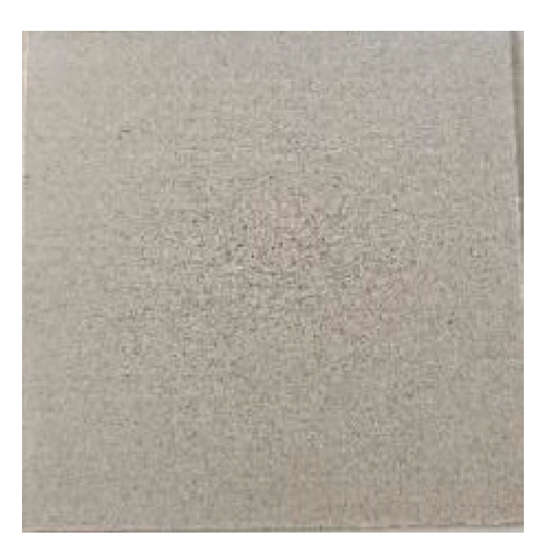
The vermiculite-based sealing plates used in the CT scanning experiments were obtained from Zhejiang Guotai Xiaoxing Sealing Material Co(
Figure 1). These plates were transformed into small cubes measuring 1.5 mm on each side. The basic physical parameters of the samples are presented in
Table 1.
Computed tomography, or CT scanning technology, is a non-destructive imaging technique that provides clear images with fast scanning times. The principle behind it involves the penetration of high-energy X-rays through an object, causing collision with atomic electrons outside the nucleus and resulting in energy loss. By detecting the energy difference before and after the X-rays penetrate the object, the absorption capacity of the object can be determined. If the internal structure of the object is not uniform, different parts of the same object will have different X-ray absorption capacities, providing information on the distribution of the object's internal structure.
The experiment utilized a General Electric-manufactured Phoenix v|tome|xS CT scanner as the primary instrument. The imaging parameters are detailed in
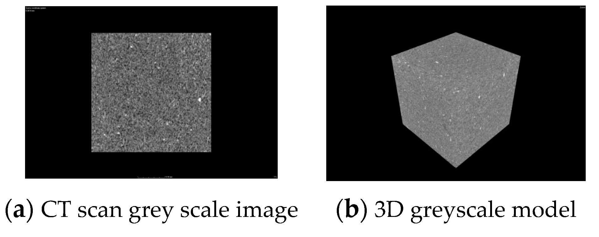
Table 2. A total of 910 2D CT slices were obtained during the experiment, as depicted in
Figure 2. The image resolution was 1478px*1009px, with voxel measurements of 0.7 μm. The high-density specimen is represented by the grey and white color, while the low-density specimen's pore space is depicted in black. A reconstructed 3D grey scale model of the sample was obtained from the scanned effective greyscale image, as shown in
Figure 2.
2. 3D Reconstruction of Pore Structure of Vermiculite Material
2.1. Image Noise Reduction
The CT scanning process reconstructs images that contain non-quantum noise and impulse noise. These noises interfere with the distribution of the image's grey value, leading to the accuracy degradation of the model. Therefore, there is a requirement to reduce the noise in the picture. Typically, the commonly used methods of noise reduction are Gaussian, median, and mean filtering. Zhu Honglin [
9] and Lv Bangmin [
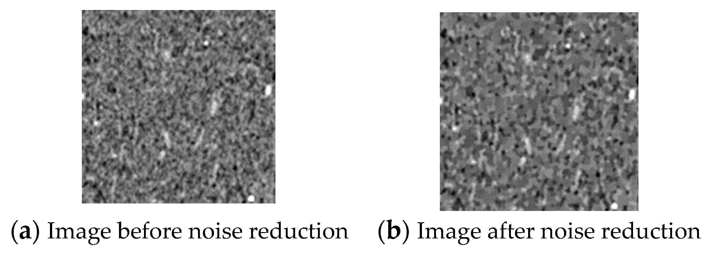
10] utilized the median filtering algorithm to process grey-scale images of porous carbon and multi-low-permeability sandstone. This approach considerably mitigated the effects of pretzel noise on the images. In this paper, median filtering has been applied to the images as shown in
Figure 3, depicting the photos before and after undergoing the noise reduction process. The results demonstrate the elimination of small noise points and the filling of small pores, thereby improving image smoothness. This outcome proves to be a useful prerequisite for accurate segmentation and quantitative analysis in subsequent studies.
2.2. Threshold Segmentation
Image segmentation involves dividing an image into regions based on similar values of features such as greyscale, color, texture, or geometry. In this experiment, the regions of interest are the skeleton region and the pore space region. Commonly used methods for segmentation thresholding include the maximum class spacing variance method, maximum entropy method, and porosity-based search thresholding method. The maximum class spacing variance method and maximum entropy method are suitable when the porosity is unknown. However, when the porosity is known, the pore characteristic parameters of the porous media model can be extracted based on the porosity searching threshold. These parameters can then be verified by comparing them with the results of the mercury compression experiment [
8]. The selection of different feature thresholds determines different categories of image pixels, and choosing an appropriate threshold can improve the accuracy of image segmentation and analysis [
11,
12].
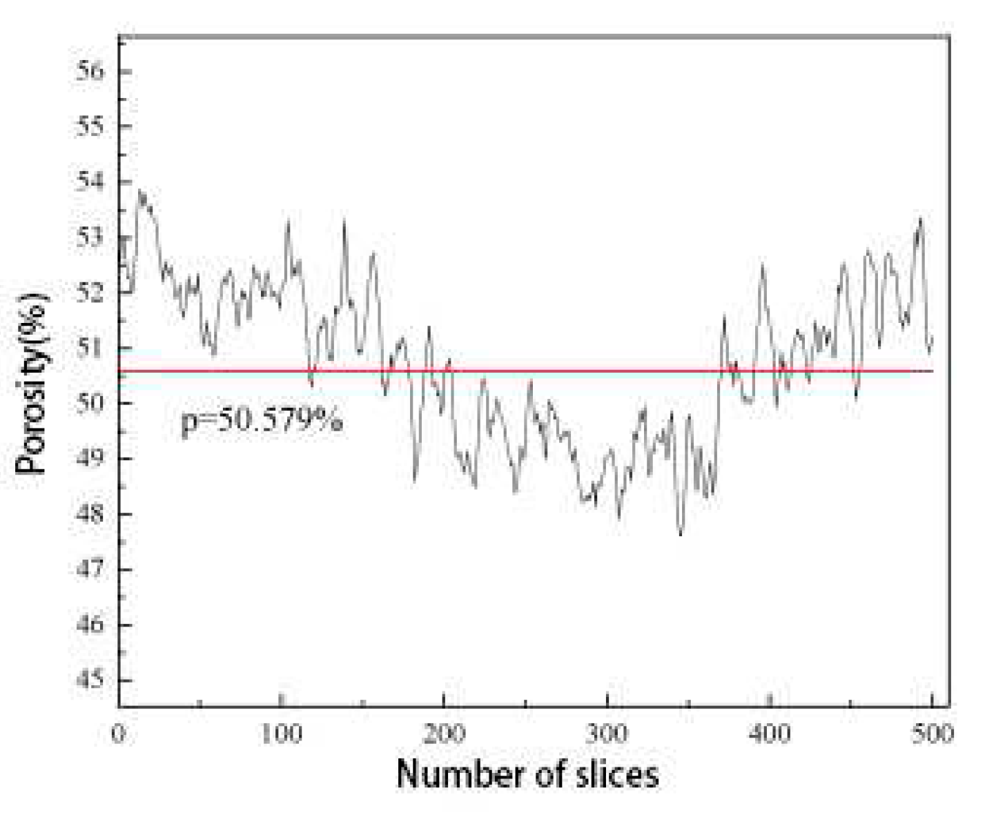
In this paper, the porosity of vermiculite-based sealing material was measured at 52.28% using the AutoPoreV 9600 system, an automated core pore penetration measurement system. This measured value served as a constraint for threshold segmentation. By iteratively adjusting the threshold value, an approximate range for the threshold value was determined, and the corresponding porosity of the vermiculite-based porous media model was calculated for each threshold value. The threshold value that yielded the smallest difference between the calculated porosity and the measured porosity was selected as the optimal threshold for segmenting the vermiculite-based sealing material. After selecting a grey value of 102, the average porosity of 500 images following threshold segmentation was found to be 50.579%, which closely aligned with the measured porosity of 52.28% obtained from the mercury compression experiment. The error fell within 3%, confirming the selection of a grey value of 102 as the final threshold value.
2.3. Three-Dimensional Reconstruction of Pores
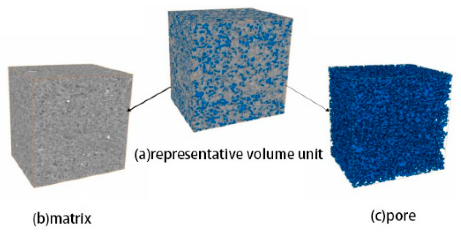
The 2D slices were imported into Avizo software sequentially. The scanning parameters such as the number of slices and voxel size were set. The volume rendering module was then utilized to create a 3D reconstruction model of the vermiculite-based sealing plate (
Figure 4). This reconstructed model provides a more realistic and intuitive representation of the spatial morphology of the skeleton and pores of the vermiculite-based sealing material. Additionally, it preserves a greater amount of information about the 3D data field.
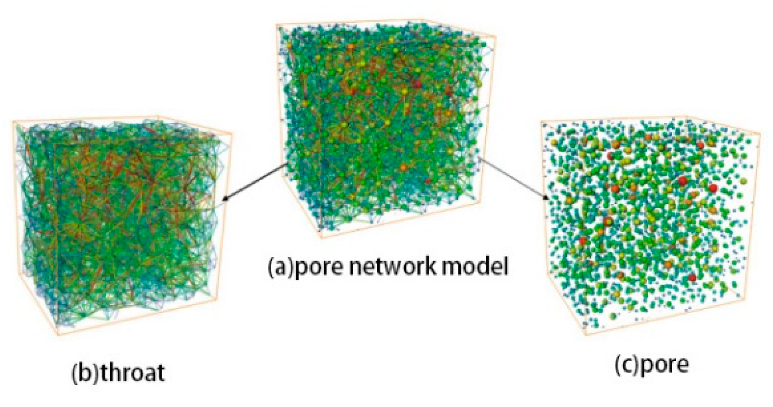
To study the internal pore structure of the samples in more detail, the corresponding pore network model was extracted using the maximum sphere method based on the reconstruction model [
15,
16]. The Separate Objects command and Generate Pore Network Model module within Avizo software were used to obtain the pore network model (
Figure 5). In this model, spheres represent internal pores, with larger spheres indicating larger pore diameters. Columns, on the other hand, represent internal throats, with thicker columns indicating larger throat radii. The length of the columns represents the length of the throats, with longer columns indicating longer throat lengths. The pore network model, also known as the ball-and-stick model, provides a visual representation of the connectivity characteristics of the sample pores.
2.4. Construction of Finite Element Models
The following steps are performed to create a finite element model under compression: checking and optimizing the mesh quality, obtaining the compression resilience curve of the vermiculite gasket, writing the velocity UDF, and constructing the compression state model.
Avizo's Meshing module can generate meshes for the reconstructed sample model. However, even with the "High" setting for Mesh Quality, some low-quality meshes may still be produced. Avizo can detect and repair unreasonable meshes, as depicted in
Figure 6. Mesh irregularities can be identified and resolved by translating and merging vertices.
The thickness of the vermiculite-based sealing material ranges from 0.8 mm to 1.5 mm. Due to this thinness, it is not feasible to directly perform compression tests and CT scan analysis. Instead, a porous media model in a compressed state needs to be established by moving the boundaries of the original state porous media model. The moving grid method is employed to handle boundary movement, allowing for the changing shape of the flow field over time. In this study, a vermiculite-based porous media model in compression is constructed using this method. In the dynamic mesh method, there are various approaches to iteratively repair the mesh. These include the dynamic layer method, mesh smoothing method, and mesh reconstruction method. Among the mesh smoothing methods, the diffusion smoothing method is chosen due to its moderate computational volume and superior mesh quality. However, when the mesh deformation reaches a certain extent, it becomes necessary to utilize the mesh reconstruction method. Therefore, this paper utilizes both the diffusion smooth method and the mesh reconstruction method.
To solve the boundary motion problem using a dynamic mesh, it is necessary to write a velocity UDF (User-Defined Function) and compile it. This paper achieves the velocity curve by conducting a gasket compression rebound experiment using a 304-punched vermiculite-reinforced gasket as the research object. The gasket compression rate, rebound rate, and compression rebound curve are obtained by referring to the compression rebound experimental test standard GB/T 12622-2008.
Table 3 and
Table 4 provide information on the gasket parameters and experimental results.
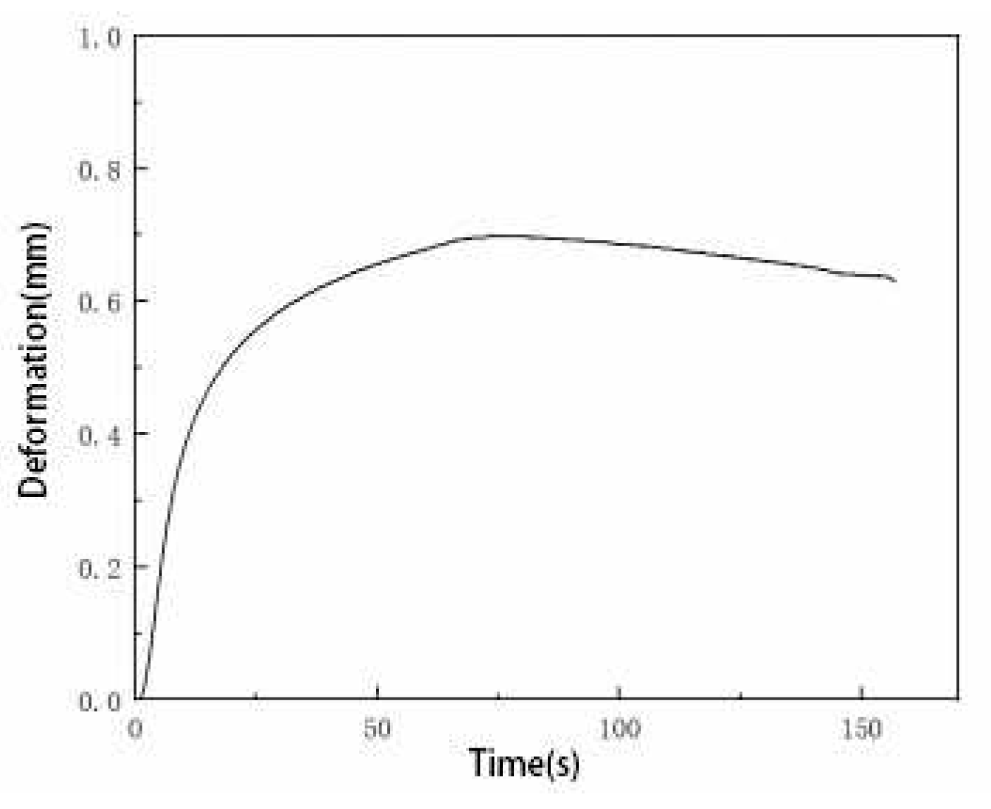
The velocity versus time equation and velocity UDF were derived by scaling the compression resilience curves (
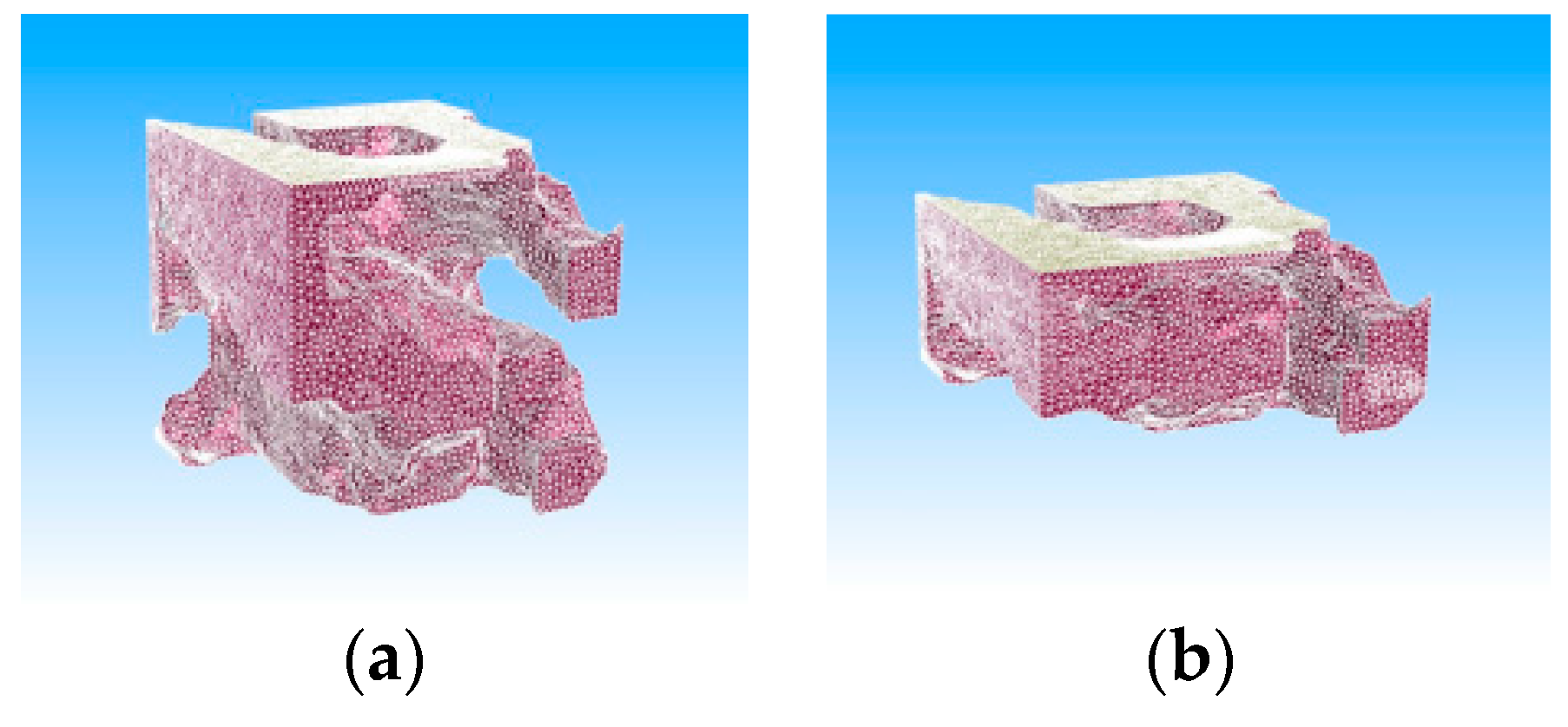
Figure 7) of vermiculite reinforced shims at 35 MPa in equal proportions. The velocity UDF was implemented in Fluent and the compression process of the shims was performed using the diffusion smoothness method and mesh reconstruction method of dynamic mesh technique. By adjusting the time step length and the number of time steps, any potential error-reporting issues during the compression process were resolved. The final compressed model was obtained (
Figure 8). The compression speed initially increases and then slows down, while the compression amount is approximately half of the thickness of the original porous medium model, which correlates with the actual compression of the shim.
3. Quantification and Characterisation of Microscopic Pore Structure
A 3D reconstruction model and an equivalent pore network model were developed for vermiculite-based sealing materials, with porosity as the constraint. The structural parameters of both models were counted and compared to the results of mercury compression experiments to verify their accuracy. The seepage simulation results were qualitatively analyzed to evaluate the rationality of the reconstructed models [
17,
18,
19]. Additionally, the study explores the size effect of the characteristic parameters of the reconstructed model and identifies the minimum model size capable of representing the overall properties.
3.1. Analysis of Three-Dimensional Pore Space Structure
The porosity of a porous material refers to the ratio of the total volume of pores to the total volume of the material. To determine the face porosity of the material, the area of each slice pore is divided by the total area of the slice. By counting the surface porosity of each section sequentially, it is evident from
Figure 9 that the porosity of each section of the reconstructed model fluctuates. However, the overall cross-section porosity falls within the range of 47.60% - 53.87%. The sample's average porosity was calculated to be 50.579%, slightly lower than the 52.28% obtained from the mercury compression experiment. This discrepancy can be attributed to the limitations of the scanning equipment's accuracy, which prevented the scanning of pores that were too small in size.
As depicted in
Figure 10, the majority of pore diameters fall within the range of 2-4 μm, constituting 70% of the total. The highest number of pores, accounting for 60% of the total, have pore areas ranging from 10 μm
2 to 20 μm
2. Similarly, the largest proportion of pores, making up 60% of the total, corresponds to pore volumes ranging from 5 μm
3 to 15 μm
3.
In addition to characterizing reconstructive models using parameters like porosity, pore diameter, and pore volume, tortuosity, and volume fractal dimension can also serve as characteristic parameters for evaluating reconstructive models. Tortuosity measures the curvature of fluid flow in the pore space, while volume fractal dimension measures the irregularity of the complex object and the efficiency of space occupation. These eigenvalues closely resemble the results of the mercury compression experiments (
Table 5), suggesting that the spatial geometry and topology of the reconstructed model closely resemble the actual pore structure.
3.2. Analysis of Hole Throat Dimensions
The maximum sphere method was utilized to create the pore network model. To determine the characteristic parameters of the pore and throat, the pore diameter and throat diameter were determined by measuring the internal tangential diameter of the largest sphere that could fit into them. Additionally, the throat length was measured as the distance between two connected pore spaces. The statistical results of extracting the characteristic parameters of the pore network model, including the throat diameter, throat length, and coordination number, are displayed in
Figure 11.
In combination with
Figure 11 and
Table 6, it is evident that 50% of the total throats with diameters ranging from 1-5 μm and 55% of the total throats with lengths ranging from 7-12 μm indicate a more uniform distribution of throat sizes. The coordination number represents the number of throat channels connected to a pore, which reflects the pore space topology of the material. Approximately 50% of the pores have a coordination number between 3-14, while around 35% of the pores have a coordination number of 0, also known as independent or "island" pores. A higher coordination number signifies improved pore connectivity. The coordination number influences the porosity, compressibility, and permeability of the sample.
3.3. Qualitative Analysis of Seepage Processes
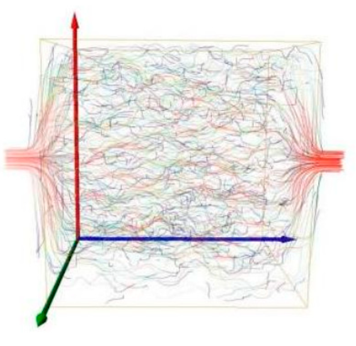
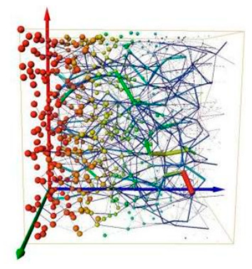
The Avizo software was used to conduct a seepage simulation of the vermiculite 3D reconstruction model. This simulation aimed to qualitatively analyze the seepage pattern and verify the model's reasonableness. The model assumed that a single-phase fluid moves from the left side to the right side along the blue Z-axis. The left and right sides of the model were designated as the pressure inlet and outlet, with pressures of 1.1 MPa and 0.1 MPa respectively. The hydrodynamic viscosity was set to 0.001 Pa·s. The flow lines' continuity and distribution indicate the connection status of the orifice throat. The simulation results of the micro-seepage in the three-dimensional reconstructed model can be seen in
Figure 12 and
Figure 13.
The arrangement of flow lines illustrates the path of fluid movement within the porous material. Consistent flow lines suggest well-connected pores, while intermittent flow lines suggest poor pore connectivity. The color of the flow lines corresponds to the speed of flow, with red indicating a fast rate and blue indicating a slow rate. In the reconstructed model, the central region shows fully red flow lines, indicating the presence of pores with numerous connections, forming a comprehensive seepage channel. On the other hand, the blue flow line at the edge is fragmented, representing the flow condition within the silos.
The ball-and-stick model illustrates the pressure and flow distribution in different regions of the sample. The sphere's size and color indicate the pressure level near the pore, while the stick's thickness and color represent the flow amount in the throat. Upon analyzing
Figure 13, it becomes evident that the pressure within the pore gradually diminishes in the direction of water flow. The maximum pressure is observed at the inlet, while it decreases towards the outlet. Similarly, the flow rate in the throat is minimal at the boundary and increases as we move closer to the center, mirroring the flow rate distribution.
3.4. Table Cell Extraction
The Representative Elementar Volume (REV) is carefully chosen to effectively represent the overall nature and fulfill the requirements of devices like computers [
13,
14].
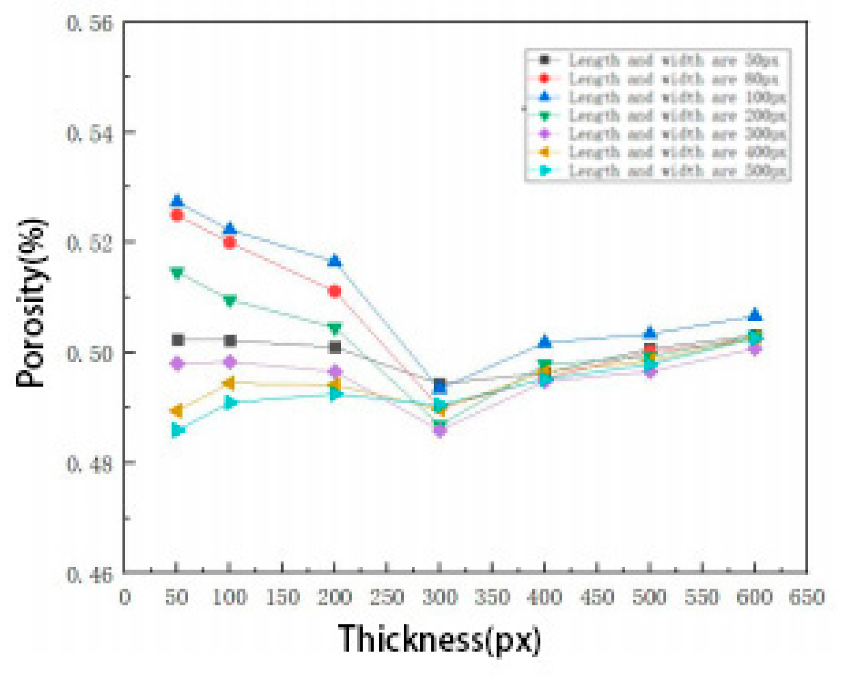
By analyzing the porosity variation curves of models with different shapes (
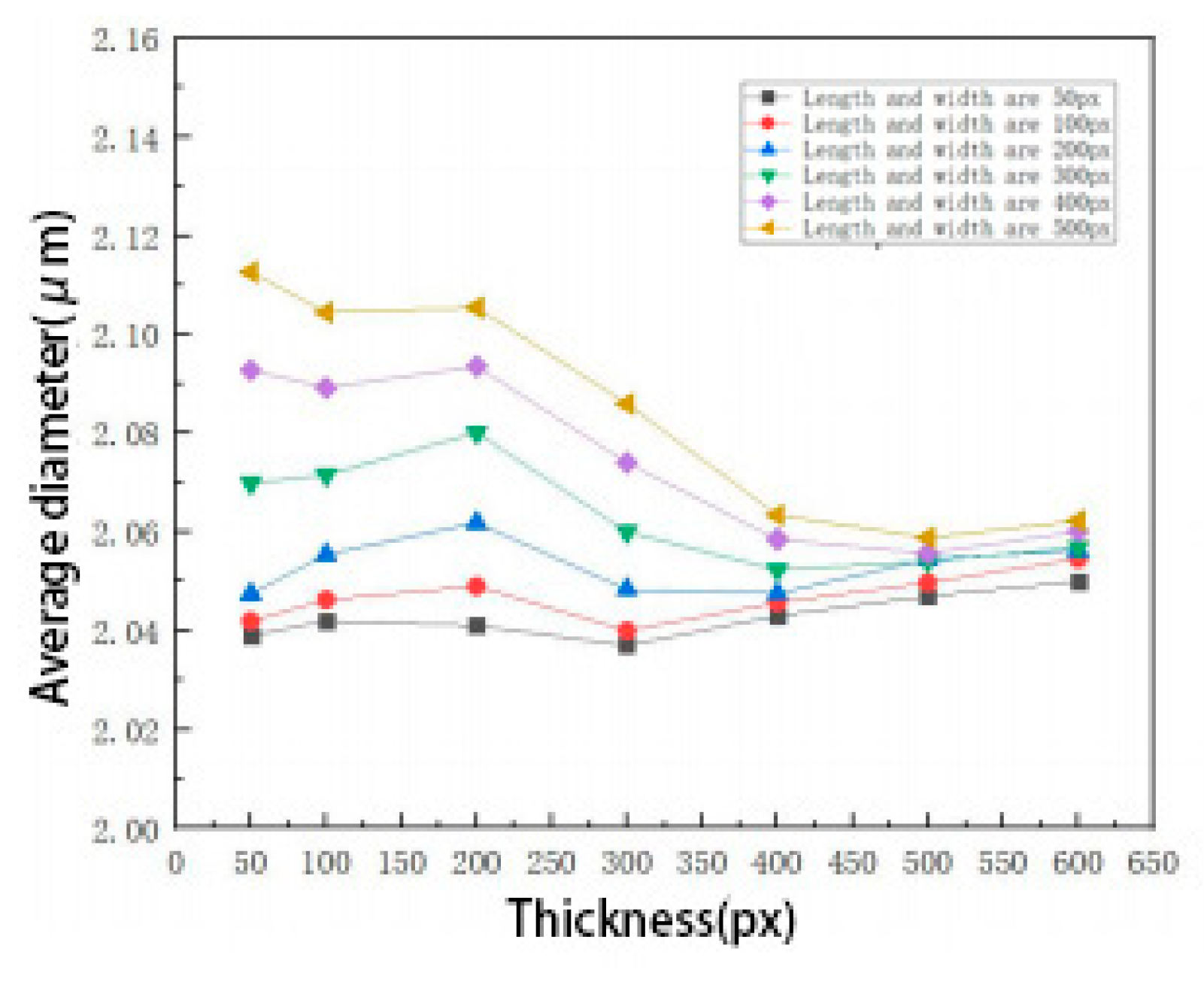
Figure 14), it can be observed that when the model thickness is less than 500 pixels, the porosity is unstable. However, when the model thickness is equal to or greater than 500 pixels, the porosity becomes more stable and shows minimal increase with the increase in representative volume cell size. The effect of thickness on pore diameter is similar to its effect on porosity (
Figure 15). When the model thickness is less than 500 pixels, the pore diameter value is unstable. On the other hand, when the model thickness is equal to or greater than 500 pixels, the pore diameter becomes stable and closely matches the average diameter value of 1.211 nm obtained from Hg-pressure experiments. Consequently, a square with a side length of 50 pixels is selected as the representative volume cell.
As the volume of the 3D reconstructed model varies, parameters like porosity and mean diameter also change. This implies that the 3D reconstructed model exhibits a scaling effect. Consequently, a square reconstruction model with a side length of 50 pixels is examined to draw conclusions that can be applied to larger-sized models.
4. Simulation of Seepage in Vermiculite Based Porous Media
4.1. Control Equations and Boundary Conditions
The simulation is based on a three-dimensional reconstructed model that replicates the real pore structure and includes seepage simulation. The research methods used in this study can be divided into two categories: the traditional method of computational fluid dynamics (CFD) and the lattice Boltzmann method (LBM). CFD involves solving the equations of conservation of mass, momentum, and energy by discretizing the model and controlling equations. On the other hand, LBM is based on the theory of molecular motion and simulates the fluid as particles with mass but no volume. By simulating the collision and movement of these particles in a lattice, a simplified kinematic model is built to reflect the fluid seepage behavior in the pore space [
20]. In this paper, the seepage flow in porous media is numerically modeled using the incompressible Navier-Stokes equations module in CFD. The equations used in the simulation are as follows:
Where: ρ_w represents the fluid density in kg·m-3; p represents the pressure in Pa; I is the unit matrix; μ is the hydrodynamic viscosity in Pa·s; F represents the volumetric force in N·m-3; u is the flow velocity in m·s-1; and g is the gravitational acceleration in m·s-2.
The fluid properties are assigned values based on the corresponding parameters at room temperature. The leftmost side of the porous medium model is designated as the inlet boundary, the rightmost side as the outlet boundary, and the four sides are set as free-slip wall surfaces, while the remaining wall surfaces are considered as no-slip wall surfaces. The inlet pressure is set to 2.1MPa, 4.1MPa, 6.1MPa, and 8.1MPa, while the outlet pressure is set to 0.1MPa. Seepage simulation is conducted for both the porous media model in its original state and its compressed state.
To simplify the simulation and analysis process, the following assumptions are made: (1) the fluid only flows within the pores of the material, without penetrating the skeleton matrix or reacting with the skeleton particles; (2) the outlet flow rate is monitored using the steady-state method, and the simulation terminates when the flow rate shows a regular cyclic change or remains essentially constant; (3) the fluid is only influenced by gravity and pressure.
4.2. Seepage in Porous Media with Different Pressure Gradients
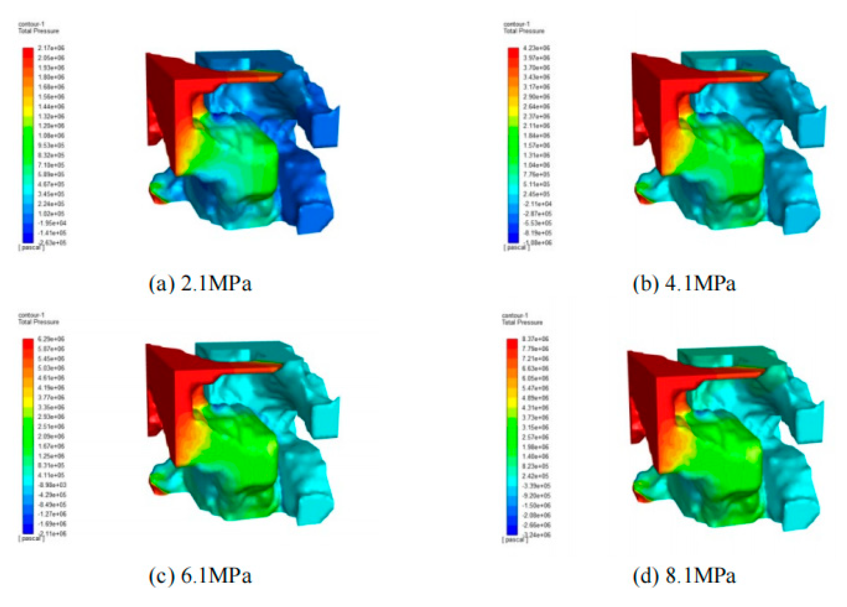
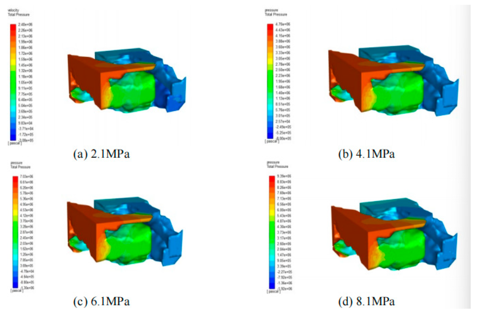
The seepage simulation includes the original state model and the compression state model. The seepage of porous media is demonstrated under different inlet pressures of 2.1 MPa, 4.1 MPa, 6.1 MPa, 8.1 MPa, and outlet pressure of 0.1 MPa, as shown in
Figure 16 and
Figure 17.
Figure 16 and
Figure 17 demonstrate that altering the inlet pressure minimally impacts the overall pressure gradient pattern within the porous medium. Elevating the inlet pressure results in a rapid expansion of the high-pressure zone and a swift reduction of the low-pressure zone. Subsequently raising the inlet pressure leads to a slower expansion of the high-pressure zone and a slower reduction of the low-pressure zone. This overall pressure trend suggests that the spatial distribution of the pore structure in the porous medium is non-uniform.
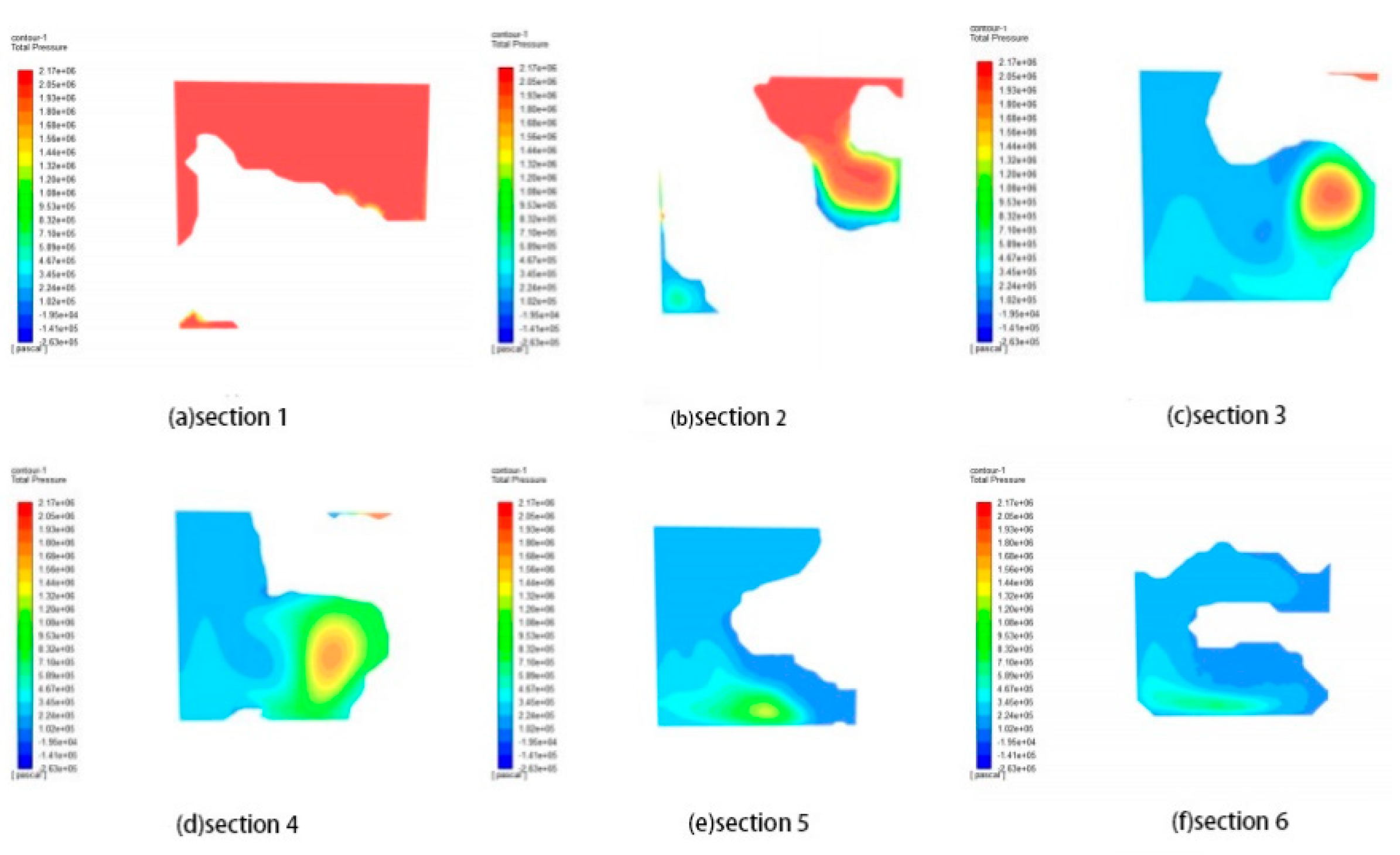
The original porous media model and the compressed porous media model were divided into five equal sections from the inlet to the outlet, parallel to the inlet surface.
Figure 18 and
Figure 19 display the pressure distributions from section 1 to section 6 of the original porous media model and the compressed porous media model at 2.1 MPa, respectively. As the compression state intensifies in the porous media model, the pore size proportionally decreases, resulting in a decrease in the differential pressure of the same cross-section. The flow rate, mass flow rate, and leakage rate all experience a slight decrease. However, the overall pressure change follows the pattern of a gradual decrease from the inlet to the outlet.
Table 7 and
Table 8 further validate this observation.
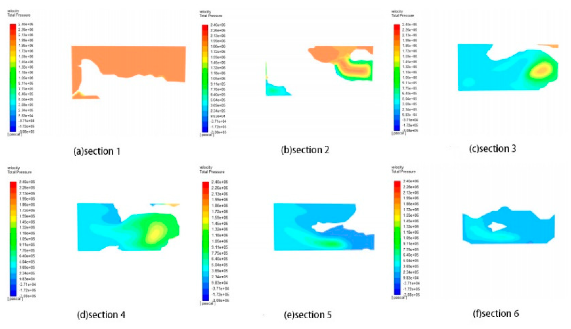
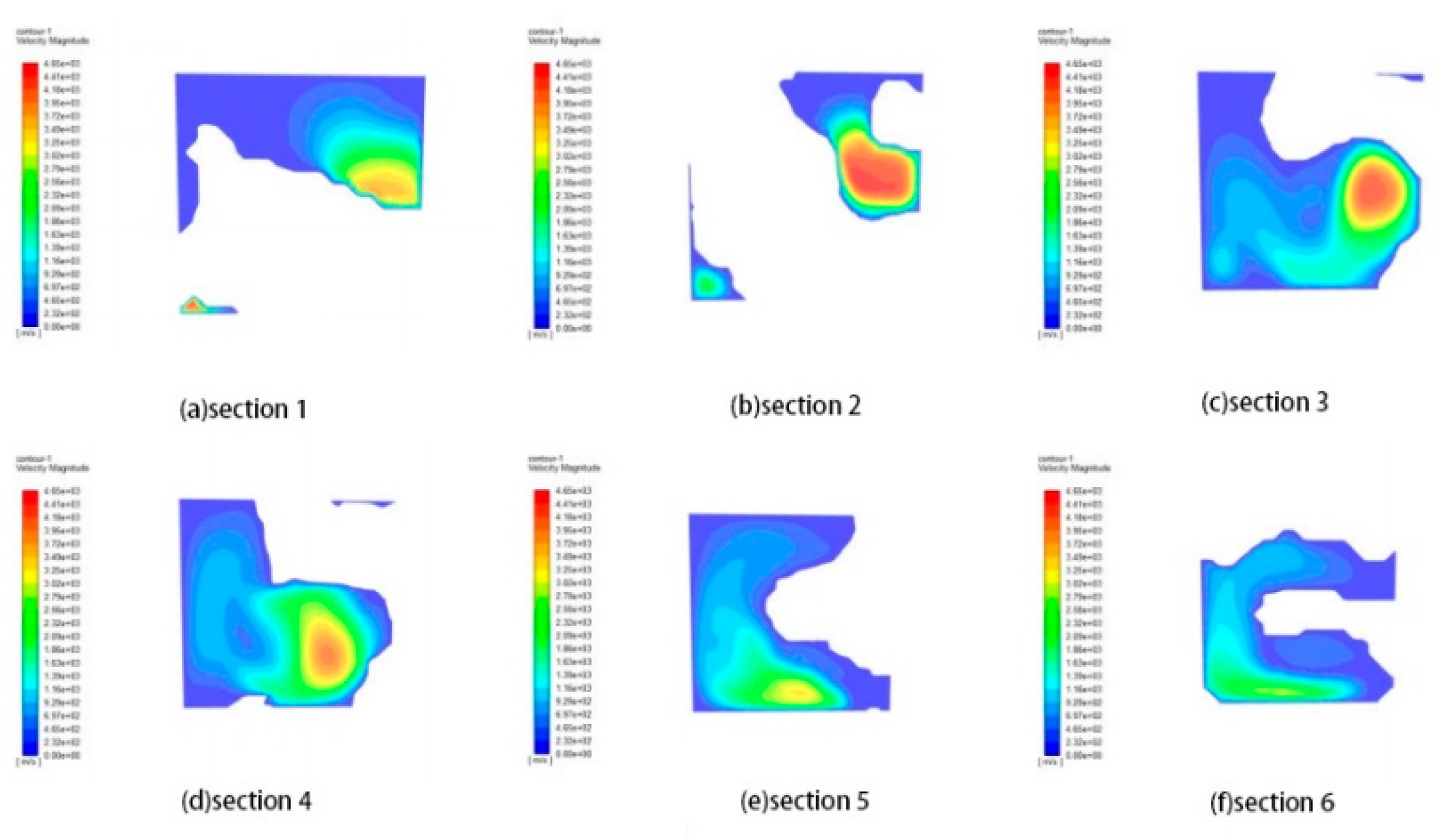
Based on
Figure 20 and
Figure 21, the velocity distribution is consistent across various sections, both in the original and compressed states. The middle section exhibits high flow rates due to incomplete development at the beginning of the fluid medium. Once the middle is fully developed, the flow rate reaches its maximum. The relationship between export flow rate and inlet pressure is non-linear, with the former increasing as the latter rises. The rate of increase slows down after an initial rapid increase.
The leakage rate of the original state and compression state porous media model is given in
Table 7 and
Table 8, respectively, and is measured in 10
-7m3/s. Comparing the two, it is evident that the leakage rate of the compression state porous media model is lower than that of the original state porous media model. This indicates that the compression state significantly affects the leakage rate of vermiculite gaskets.
5. Conclusion
(1) Using CT scanning experiments and digital image processing techniques, a digital core model of dense plates made from vermiculite was created. Additionally, an equivalent model of the pore network was established using the maximal sphere method. This allowed for statistical analysis and examination of pore geometry and topological structure parameters.
(2) The reconstructed model's pore structure parameters were compared to the results obtained from the mercury pressure experiment, demonstrating its accuracy and representativeness.
(3) By utilizing Avizo, the pore mesh can be repaired, and when combined with Fluent software, it enables intuitive simulation of seepage flow at the microscopic scale. This research expands the application of CT scanning technology in the mechanical seal field and offers a novel approach to studying permeation leakage of non-metallic gaskets.
Funding
This work was supported by National key research and development program (2020YFB2008000)
References
- GUO Quan,DING Mingwei. Selection of sealing materials under high-temperature working conditions[J]. Chemical Equipment and Piping,2018,55(03):72-76.
- JIANG Xuefeng. Preparation and research of vermiculite-based high temperature resistant flexible sealing material[D]. Hubei: Wuhan University of Technology,2020.
- Hoyes J, Bond S. Gaskets for sealing solid oxide fuel cells[J].Seal Technology. 2007, 8:11–14. [CrossRef]
- Rosenberg E., Lynch J., Gueroult P. High Resolution 3D Reconstructions of Rocks and Composites[J].Oil & Gas Science and Technology.1999,54(4):497-511.
- Ams C.H.The Influence of Morphology On Physical Properties of Reservoir Rocks[D].Sydney: The University of New South Wales,2002.
- Su Na. Three-dimensional reconstruction of microscopic pore structure in low-permeability gas reservoirs[D]. Sichuan: Southwest Petroleum University,2011.
- Li Ying,Zhang Lanzhu. Modeling and evaluation of bionic bone scaffolds based on gradient function[J]. Computer Simulation,2022,39(04):381-386+449.
- He KK. Characterization of multi-scale pore and fracture development in coal based on CT[D]. Henan University of Technology,2018.
- Zhu Honglin. Research on pore structure characterization and application in low permeability sandstone reservoir [D]. Chengdu: Southwest Petroleum University, 2014.
- Lv Bangmin. Research on pore three-dimensional characterization and permeability of coal-based porous carbon [D]. Xuzhou: China University of Mining and Technology, 2019.
- WANG G,SHEN J N,CHU X Y,et al. Characterization and analysis of pores and fissures of high-rank coal based on CT three-dimensional reconstruction[J]. Journal of China Coal Society,2017,42(8):2074–2080.
- LIU X J, ZHU H L, LIANG L X. Digital rock physics of sandstone based on micro-CT technology[J]. Chinese Journal of Geophysics,2014,57(4):1133–1140. [CrossRef]
- HARPREET Singh. Representative elementary volume(REV) in the spatio-temporal domain: A method to find REV for dynamic pores[J]. Journal of Earth Science,2017,28(2),391–403. [CrossRef]
- YUAN Chao,CHAREYRE Bruno,DARVE Félix. Pore-scale simulations of drainage in granular materials: Finite size effects and the representative elementary volume[J]. Advances in Water Resources,2016,95:109–124. [CrossRef]
- Blunt M J, Jackson M D, Piri M, Valvatne PH. Detailed physics, predictive capabilities and macroscopic consequences for pore-network models of multiphase flow[J].Adv.Water Resour. 2002, 25: 1069-1089. [CrossRef]
- Al-GharbiM S.Dynamic pore-scalemodelling of two-phase flow[D].Imperial College, 2004.
- WU Y Q, LIN C Y, REN L H, et al. Digital core modeling based on multiple-point statistics[J]. Journal of China University of Petroleum(Edition of Natural Science),2018,42(3):12-21.
- LIU T T, WEN F X, ZHAO C G, et al.Mesoscale pore structure analysis and seepage simulation of cast-in-situ vegetation concrete[J].China Rural Water and Hydropower,2020(10):88-93,105.
- ZHANG W Z, QIU L. Characterization and analysis of pore structure of coal based on CT 3D reconstruction[J].CoalTechnology.2018,37(12):327-329.
- Zhang Yongchao, Liu Changling, Wu Nengyou, et al. Characteristics of pore structure and microscopic seepage simulation of hydrate-bearing sediments[J]. Frontiers of Marine Geology, 2020, 36(9):23.33.
Figure 1.
Sample of vermiculite based sealing material.
Figure 1.
Sample of vermiculite based sealing material.
Figure 2.
Gray scale image of vermiculite based sealing material.
Figure 2.
Gray scale image of vermiculite based sealing material.
Figure 3.
Grayscale images before and after noise reduction.
Figure 3.
Grayscale images before and after noise reduction.
Figure 4.
3D reconstruction of vermiculite-based sealing sheet.
Figure 4.
3D reconstruction of vermiculite-based sealing sheet.
Figure 5.
Pore network model.
Figure 5.
Pore network model.
Figure 6.
Mesh optimization and restoration.
Figure 6.
Mesh optimization and restoration.
Figure 7.
Compression rebound curve of 35MPa vermiculite reinforced gasket.
Figure 7.
Compression rebound curve of 35MPa vermiculite reinforced gasket.
Figure 8.
Model in original state (left) and model in compressed state (right).
Figure 8.
Model in original state (left) and model in compressed state (right).
Figure 9.
Surface porosity distribution.
Figure 9.
Surface porosity distribution.
Figure 10.
Distribution statistics of pore space structure parameters.
Figure 10.
Distribution statistics of pore space structure parameters.
Figure 11.
Statistics of hole size distribution.
Figure 11.
Statistics of hole size distribution.
Figure 12.
Seepage flow line distribution.
Figure 12.
Seepage flow line distribution.
Figure 13.
The pressure and flow distributions.
Figure 13.
The pressure and flow distributions.
Figure 14.
Different thickness, length and width correspond to porosity curves.
Figure 14.
Different thickness, length and width correspond to porosity curves.
Figure 15.
Different thickness, length and width correspond to the average diameter curve.
Figure 15.
Different thickness, length and width correspond to the average diameter curve.
Figure 16.
Pressure distribution of the original state porous media model under various pressures.
Figure 16.
Pressure distribution of the original state porous media model under various pressures.
Figure 17.
Pressure distribution of porous media model in compression state under various pressures.
Figure 17.
Pressure distribution of porous media model in compression state under various pressures.
Figure 18.
2.1 MPa original state porous media model pressure distribution in each section.
Figure 18.
2.1 MPa original state porous media model pressure distribution in each section.
Figure 19.
2.1 MPa compression state porous media model pressure distribution in each section.
Figure 19.
2.1 MPa compression state porous media model pressure distribution in each section.
Figure 20.
2.1 MPa velocity distribution of the porous media model in the original and compressed states.
Figure 20.
2.1 MPa velocity distribution of the porous media model in the original and compressed states.
Figure 21.
2.1 MPa velocity distribution of each section of the porous media model in the original state.
Figure 21.
2.1 MPa velocity distribution of each section of the porous media model in the original state.
Table 1.
Basic parameters of vermiculite based sealing material.
Table 1.
Basic parameters of vermiculite based sealing material.
| Samples |
Density (g/cm3 ) |
Specific surface area (m²/g) |
Elemental analysis (%) |
| O |
Si |
Mg |
C |
| Vermiculite sheet |
1.1-1.13 |
0.82 |
35.80 |
23.71 |
15.89 |
6.80 |
Table 2.
CT scanner working parameters.
Table 2.
CT scanner working parameters.
| Parameters |
Name |
Maximum tube voltage (kV) |
Maximum tube power (W) |
Minimum distance from focal point to workpiece (mm) |
| Norm |
Phoenix v|tome|x S |
240 |
320 |
4.5 |
Table 3.
Dimension parameters of 304 punching vermiculite reinforced gasket.
Table 3.
Dimension parameters of 304 punching vermiculite reinforced gasket.
| Name of sample |
Nominal Diameter |
Nominal pressure |
Gasket type |
Gasket Standard |
Sizes (mm) |
| 304 Punch Vermiculite Reinforced Gasket |
DN80 |
PN63 |
Convex surface (RF) |
HG/T20606-2009 |
89*148*3 |
Table 4.
Results of compression and rebound by 304 sprint vermiculite reinforced gasket.
Table 4.
Results of compression and rebound by 304 sprint vermiculite reinforced gasket.
| Name of sample |
Load (MPa) |
No. |
Compression ratio (%) |
Rebound rate (%) |
| 304 Punch Vermiculite Reinforced Gasket |
35 |
1 |
33.33 |
8.57 |
| 2 |
33.18 |
9.86 |
| 3 |
33.33 |
10.61 |
| Average value |
33.28 |
9.68 |
Table 5.
Comparison of reconstructed model parameters and mercury intrusion experiment results.
Table 5.
Comparison of reconstructed model parameters and mercury intrusion experiment results.
| Parameters |
Reconstructed model |
Mercury compression experiment |
| Aperture /μm3
|
2.17E+07 |
2.48E+07 |
| Totality /μm3
|
4.29E+07 |
4.75E+07 |
| Body porosity /% |
50.579 |
52.28 |
| Face porosity /% |
47.60-53.87 |
52.28 |
| Average pore size /nm |
2336 |
1211.49 |
| Tortuosity |
1-10.9058 |
4.30 |
| Dimensionality of a volume fractal |
2.75 |
2.999 |
Table 6.
Statistics of quantitative parameters of pore network model.
Table 6.
Statistics of quantitative parameters of pore network model.
| Parametric |
Throat Diameter(μm) |
Length of throat(μm) |
Coordination number |
| Minimum value |
0.41 |
2.28 |
0 |
| Maximum values |
34.54 |
82.04 |
52 |
| Average value |
2.84 |
10.39 |
7 |
Table 7.
Leakage rate of original porous media model.
Table 7.
Leakage rate of original porous media model.
| Leak rate (m3/s) |
Strains (MPa) |
| 2.1 |
4.1 |
6.1 |
8.1 |
| He |
3.958529E+07 |
5.958315E+07 |
7.554999E+07 |
8.935514E+07 |
Table 8.
Leakage rate of porous media model under compression.
Table 8.
Leakage rate of porous media model under compression.
| Leak rate (m3/s) |
Strains (MPa) |
| 2.1 |
4.1 |
6.1 |
8.1 |
| He |
2.306919E+07 |
3.502845E+07 |
4.450683E+07 |
5.268679E+07 |
|
Disclaimer/Publisher’s Note: The statements, opinions and data contained in all publications are solely those of the individual author(s) and contributor(s) and not of MDPI and/or the editor(s). MDPI and/or the editor(s) disclaim responsibility for any injury to people or property resulting from any ideas, methods, instructions or products referred to in the content. |
© 2023 by the authors. Licensee MDPI, Basel, Switzerland. This article is an open access article distributed under the terms and conditions of the Creative Commons Attribution (CC BY) license (https://creativecommons.org/licenses/by/4.0/).
