Preprint
Article

Research on Secure State Estimation and Recovery Control for CPS under Stealthy Attacks

Altmetrics

Downloads

98

Views

13

Comments

0

A peer-reviewed article of this preprint also exists.

This version is not peer-reviewed

Submitted:

27 September 2023

Posted:

29 September 2023

You are already at the latest version

Alerts
Abstract
As the application of cyber-physical systems (CPSs) becomes more and more widespread, its security is becoming a focus of attention. Currently, there has been much research on the security defense of the physical layer of the CPS. However, most of the research only focuses on one of the aspects, for example, attack detection, security state estimation or recovery control. Obviously, the effectiveness of security defense targeting only one aspect is limited. Therefore, in this paper, a set of security defense processes is proposed for the case that a CPS containing multiple sensors is subject to three kinds of stealthy attacks (i.e., zero-dynamics attack, covert attack, and replay attack). Firstly, the existing attack detection method based on improved residuals is used to detect stealthy attacks. Secondly, based on the detection results, an optimal state estimation method based on improved Kalman filtering is proposed to estimate the actual state of the system. Then, based on the optimal state, internal model control (IMC) is introduced to complete the recovery control of the system. Finally, the proposed methods are integrated to give a complete security defense process, and the simulation is verified for three kinds of stealthy attacks. The simulation results show that the proposed methods are effective.
Keywords: 
Subject: Engineering  -   Control and Systems Engineering

1. Introduction

Cyber-physical systems (CPSs) are cyber systems consisting of cyber (computing and communication) and physical (sensors and actuators) components that interact in a feedback loop with the help of possible human intervention, interaction, and exploitation [1]. Due to the tight integration of physical processes, networks, and computing, current CPSs are widely used in different fields, such as power transmission systems, healthcare, communication systems, military systems, transportation, automotive systems, entertainment, and many other areas directly related to people’s daily lives [2,3]. However, the interconnection of the cyber and physical worlds has brought new and dangerous security challenges. For example, in the information network area, in 2003, many websites and Internet services were rendered inaccessible because they were hit by the Sapphire worm [4]. In the energy sector, in 2010, the Stuxnet virus attacked Iran’s nuclear power plant, destroying its centrifuges, and rendering the nuclear reactor inoperable for a long time [5]. In the healthcare area, in 2017, WannaCry attacked the National Health Service, causing huge casualties and financial losses [6]. These security incidents provide sufficient evidence that attacks on CPS, which eventually penetrate actual physical processes, can lead to significant losses of people’s livelihoods. Therefore, it is important to study the security of CPSs.
The security defense problem of CPS can be mainly divided into the cyber layer and the physical layer. The defense means of the cyber layer are mainly similar to the security defense methods of the information network, for example, the defense against network attacks is achieved by encryption keys[7], watermark detection[8], and restriction of access rights[9]. However, the high coupling of CPS with real physical devices leads to the fact that some attacks against the cyber layer can also penetrate and affect the actual physical processes, especially some automatic control systems, resulting in reduced control performance. Therefore, defense against the physical layer is very important and necessary from the point of view of the last means of defense and brings worthwhile defense benefits.
The security defense problem for the physical layer of CPS can be divided into several stages: attack detection, secure state estimation, and secure control[10]. Among them, each of them has a different and necessary function. However, most of the studies focus on one of these phases for analysis and discussion only. In terms of attack detection, a blended detection scheme that appropriately uses a combination of two existing detection methods is proposed to achieve the detection of a large class of false data injection attacks[11]. In [12] , a moving target defense that introduces random, time-varying parameters in the control system is proposed to inhibit the attacker’s ability to construct a stealthy attack sequence. Combining existing concepts of watermark signals and auxiliary systems, a novel control architecture capable of detecting spoofing attacks that affect the network control system without compromising control performance is proposed[13]. In terms of secure state estimation, a Bayesian method based on random sets for switching signals and spurious measurement attacks is deployed to ensure resilient state estimation[14]. In [15] , a robust asymptotic fault estimation method is designed for CPS with sensor faults that can estimate the system state well. Considering a secure reconstruction problem for linear CPS with both sparse actuator and sensor attacks, a descriptor switched sliding mode observer that effectively reconstructs the sparse FDI attacks and the system state is constructed [16]. In terms of secure control, an architectural framework for resilient CPS based on stochastic MPC is proposed to ensure robustness in the presence of stochastic uncertainty and to achieve resilient control against cyber-attacks[17]. In [18], by analyzing various cyber-attacks, a unified system model with uncertainty is developed and the robust control theory is applied to achieve secure control of the system after an attack. A model predictive switching control strategy based on attack perception is proposed to compensate for the untrusted sequences of data caused by false data injection attacks[19].
From the above analysis, we can find that as the application of CPS expands, people pay more and more attention to the security of CPS. Although all the above studies have good results, they all focus on only one phase of CPS security defense, and rarely consider the complete security defense process. Therefore, in this paper, we consider the scenario that a CPS containing multiple sensors is subject to stealthy cyber-attacks (e.g., zero-dynamics attacks, covert attacks, and replay attacks), combine the attack detection method based on improved residuals [20], propose an optimal state estimation based on improved Kalman filtering and a recovery control strategy based on the optimal state, and give a complete framework of security defense process from attack detection to recovery control. Finally, the theory is validated by design simulation, and the results prove the feasibility of the proposed method.
The main contributions of this paper can be summarized as follows.
1) By analyzing the structural characteristics of CPS, a system model containing the attacks is developed, and stealthy attacks (i.e., zero-dynamics attacks, covert attacks, and replay attacks) and the detection method based on improved residuals are described.
2) For the case of attacks on a CPS containing multiple sensors, an optimal state estimation method based on improved Kalman filtering is proposed, which can achieve the estimation of the actual state of the CPS after the attack.
3) Based on the estimated optimal state, a recovery control strategy is designed that can achieve recovery control of the system after identifying the attack. And at the end, a framework for the security defense process is given.
The rest of this paper is organized as follows. In Section II, the CPS structure and stealthy attacks are described, and the improved residual-based attack detection method is presented. In Section III, the optimal state estimation based on the improved Kalman filter and the recovery control strategy based on the optimal state are proposed, and a complete framework of the security defense process is given. Simulation experiments are designed in Section IV, and the results are analyzed and illustrated. Section V summarizes the full work and provides an outlook for future work.

2. Model Building and Detection Methods

2.1. System Modelling

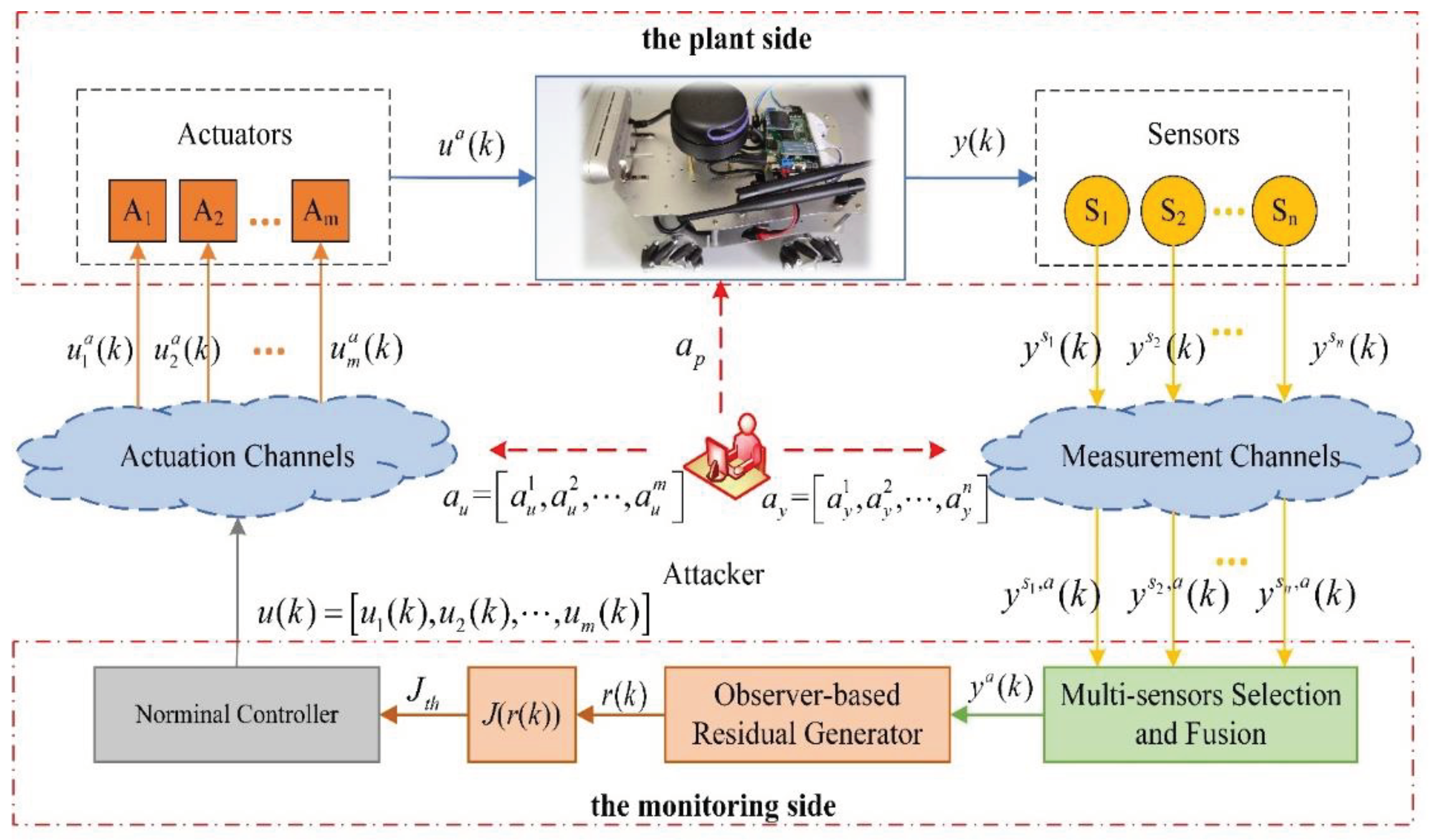
The block diagram of the CPS structure with multiple actuators and sensors considering the case of sensor attacks, actuator attacks and process attacks is shown in Figure 1. The CPS is divided into the plant side and the monitoring side. The plant side includes physical devices as well as multiple actuators and sensors, and the monitoring side mainly uses the data returned from the measurement channels to realize remote control of the physical devices. Where the monitoring side controls the actuators through control commands to achieve the desired function or action; the plant side obtains the system state through multiple sensors independently measured and transmits it to the monitoring side for generation of control commands. Since the system contains several sensors, a partial or complete system state can be obtained independently by each sensor. Therefore, in many CPSs, an additional multi-sensor selection and fusion module is added at the monitoring side, whose main purpose is, based on certain principles or methods, to obtain the final system state used to generate control commands from the many system states acquired by sensors. In addition, the attackers mainly attack the measurement channels and actuation channels as well as directly attack the physical devices, thus adversely affecting them.
The CPS model with multiple sensors, considering the case of containing attacks, is constructed as:
x ( k + 1 ) = A x ( k ) + B u ( k ) + a u ( k ) + E P a p ( k ) + w ( k ) , y s i , a ( k ) = C s i x ( k ) + D u ( k ) + a u ( k ) + a y i ( k ) + F P a p ( k ) + v i ( k ) , y a ( k ) = Φ y s 1 , a | y s 2 , a | | y s n , a .   i = 1 , 2 , , n
where, x ( k ) p is the state of the system, u ( k ) m is the control command signal output from the monitoring side of the system, u a ( k ) m is the control signal input to the plant side after the attack, y s i , a ( k ) n is the measurement output of the i t h sensor after the attack, y a ( k ) n is the system output after multi-sensor selection and fusion, a u ( k ) denotes the attack against the actuation channel, a p ( k ) denotes the process attack, and a y i ( k ) denotes the attack against the i t h measurement channel. Φ y s 1 , a | y s 2 , a | | y s n , a denotes some multi-sensor fusion method. E P , F P are known matrices indicating the locations of components in the system that may be subject to process attacks. A , B , C s i , D are the parameter matrices of the system. C s i denotes the corresponding output matrix when only the i t h sensor is considered. w ( k ) denotes the process noise and v i ( k ) denotes the measurement noise of the i t h sensor, both obeying w ( k ) N ( 0 , Σ w ) , v i ( k ) N ( 0 , Σ v i ) .
Figure 1. Block diagram of CPS structure with multiple actuators and sensors considering sensor attacks, actuator attacks and process attacks.
Preprints 86336 g001
Remark 1.
Process attacks are direct attacks on physical devices that cause damage to physical devices, and actuator attacks and sensor attacks are operations such as blocking or data tampering on the channels of signal transmission. Since process attacks directly cause damage to physical devices and to some extent there is no longer a need for defense, this paper only studies the security defense of CPS where actuator attacks or sensor attacks exist.
Remark 2.
The type of attack mentioned in (1) is of additive attack and does not change the model parameters. Here, a multiplicative attack that causes changes in the model parameters due to functional anomalies of the system, in the process or sensors and actuators due to cyber-attacks, is not considered.
Consider the CPS shown in Figure 1, where the observer-based residual detector is defined at the monitoring side as follows.
r o ( k ) = y a ( k ) C x ^ ( k )
where, y a ( k ) m denotes the measurement under attack and x ^ ( k ) n is the state estimated by the observer. r 0 ( k ) is the residual signal that satisfies r 0 ( k ) N ( 0 , Σ r 0 ) .
According to the χ 2 test, the residual evaluation function J ( ) can be written as:
J r 0 ( k ) = r 0 T ( k ) Σ r 0 1 r 0 ( k ) ~ χ 2 ( m )
So, the logic law of detection to determine the presence of an attack is expressed as:
J r 0 ( k ) J t h a t t a c k f r e e J r 0 ( k ) > J t h a t t a c k e d
When the false alarm rate α is given, the threshold J t h is set to the upper bound of χ α 2 ( m ) .

2.2. Description of Stealthy Attacks

For integrity stealthy attacks, the following definition is first given.
Definition 1.
When there is an attack in the system, given a false alarm rate α , and the attack cannot be detected based on the residual signal r 0 ( k ) using the detection logic given in (4), then the attack is said to be stealthy from the detector given in (2).
According to the definition of stealthy attacks, three types of stealthy attacks are introduced.
1) Zero-dynamics attack, it requires complete knowledge of the system model to design attack signals against the actuators. It evades the detector of (3) by adding the attack signal a u ( k ) to the actuator input without affecting the sensor measurement output, i.e., a y ( k ) = 0 [21]. Therefore, the attack form can be expressed as a u ( k ) = υ k g , where the system zero υ and the corresponding input-zero direction g can be calculated by solving the following equation.
υ I A B C 0 x 0 g = 0 0
where, x 0 is the initial state of the system for which the input sequence a u ( k ) results in an identically zero output.
2) Covert attack, it also requires complete knowledge of the system model and attacks against both actuation channels and measurement channels. In the actuation channels, the performance of the control system is affected by applying an additive signal a u ( k ) , however, in the measurement channels, the effect of the input attack on the measurement is eliminated by carefully designing a signal a y ( k ) [22]. Given the discrete linear model in (1), a y ( k ) can be calculated by the following equation.
a y ( k ) : = C i = 0 k 1 A i B a u ( k 1 i )
3) Replay attack, it does not require knowledge of the system model. It only needs to be able to access the signal transmission channels, to attack the control signals and to record and re-cover the measurement data. The replay attack can be specifically described as [23]: in the measurement channels, the measurement data in the steady-state of the system is recorded in advance, and the actual measurement values are overwritten with the recorded data when the attack is performed (i.e., y ( k ) = y ( k τ ) , τ > 0 ); while in the actuation channels, a u ( k ) is designed to affect the performance of the system. Obviously, the replay attack is stealthy in the steady-state of the system.
Remark 3.
Zero-dynamics attack, covert attack, and replay attack are all additive attacks and satisfy the stealthy condition of Definition 1. In addition, zero-dynamics attack and covert attack require complete knowledge of the system model to evade the detection mechanism of (3), while replay attack does not require it and it is stealthy when the system is stable.

2.3. Detection Method

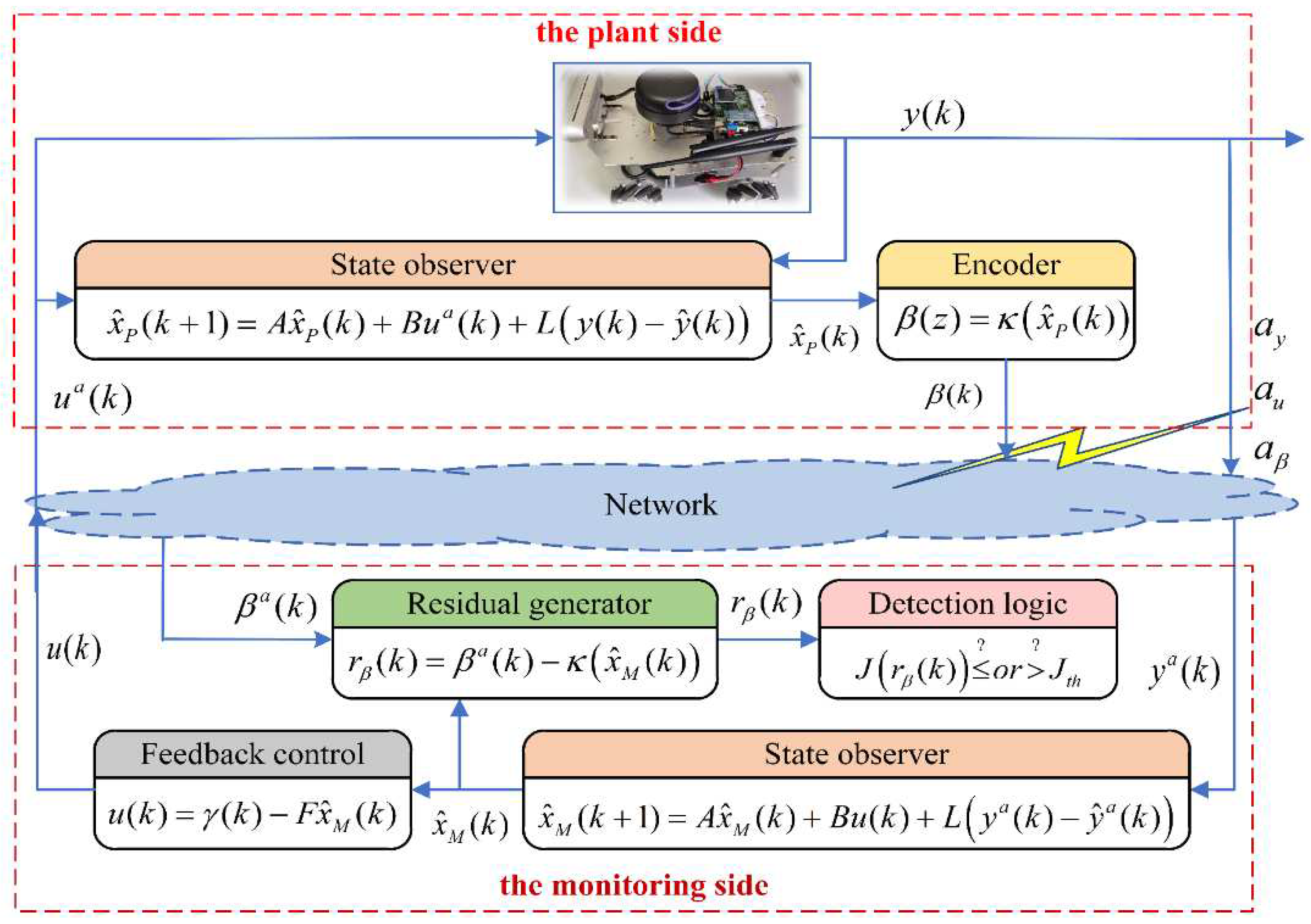
From the previous analysis of stealthy attacks, the core purpose of the three stealthy attacks is to attack the actuators to make the control performance degraded or even severely degraded, while the main purpose of the attacks against the sensors is to avoid the detection mechanism given in (3). Therefore, the detection of stealthy attacks can be achieved by exploiting the difference between the states of the system on the monitoring side and the plant side [20]. Considering the case of containing only one sensor that can independently measure the full state of the system, the detection scheme is designed as shown in Figure 2. The specific working principle is described below.
Figure 2. The scheme of attack detection based on improved residual.
Preprints 86336 g002
On the monitoring side, the observer is constructed in the following form:
x ^ M ( k + 1 ) = A x ^ M ( k ) + B u ( k ) + L y a ( k ) y ^ a ( k ) y ^ a ( k ) = C x ^ M ( k ) + D u ( k )
On the plant side, the observer is constructed in the following form:
x ^ P ( k + 1 ) = A x ^ P ( k ) + B u a ( k ) + L y ( k ) y ^ ( k ) y ^ ( k ) = C x ^ P ( k ) + D u a ( k )
From (7) and (8), it can be found that when there is no attack, x ^ P ( k ) = x ^ M ( k ) ; when there is an attack, x ^ P ( k ) x ^ M ( k ) . This is because the states on both sides are estimated based on different signals. Therefore, this difference can be used for the detection of stealthy attacks. Also, to avoid the attack when x P ( k ) is transmitted to the monitoring side, the following form of the transmission signal is designed.
β ( k ) = κ x ^ P ( k )
where, κ indicates a certain encryption policy, which is known only to the system itself.
Therefore, the residual signal used to detect stealthy attacks can be constructed as:
r β ( k ) = β ( k ) κ x ^ M ( k )

3. State Estimation and Recovery Control

The CPS is subject to various stealthy cyber-attacks, and its control performance is significantly reduced. Obviously, the main concern of both attackers and defenders is how to influence or improve the control performance of the control system to achieve the attack and defense objectives. Therefore, a well-integrated controller design solution that can detect, isolate, and recover control from attacks is a must in the face of stealthy cyber-attacks.
Consider a CPS as shown in Figure 1, containing multiple actuators as well as multiple sensors that can be independently measured to obtain the complete system output. The analysis of stealthy attacks in Section II shows that the key to their stealthy implementation lies in the tampering with the sensor measurement output, while the attack on the actuators is only to achieve the purpose of the attack and control the specific actions of the system. Therefore, considering n sensors Π s = s 1 , s 2 , , s n there are unknown sensors suffered from the attack, the specific attacks are described as follows.
y s i , a ( k ) = y s i ( k ) a t t a c k f r e e y s i ( k ) + a y i ( k ) a t t a c k e d   , i = 1 , 2 , , n .
Without knowing which sensor is under attack, it is undesirable to directly fuse the sensor output data using the multi-sensor fusion method Φ y s 1 , a | y s 2 , a | | y s n , a . Therefore, each sensor must be detected in advance and the sensor detected to be under attack must be isolated, and finally, the normal sensors are selected for fusion to obtain the correct system state for recovery control.

3.1. Optimal State Estimation Based on Improved Kalman Filtering

To detect whether each sensor is under attack, the detection method in Section II is used to calculate the residual signal for each sensor to detect stealthy attacks. Assume that the sequence of residual signals for all sensors is calculated as follows.
Θ = r β s 1 ( k ) , r β s 2 ( k ) , , r β s n ( k )
According to the χ 2 detection theory, drawing on the detection logic of (3) and (4), the detection of stealthy attacks can be achieved for each sensor.
J r β s i ( k ) J t h β a t t a c k f r e e J r β s i ( k ) > J t h β a t t a c k e d   , i = 1 , 2 , , n
Assume that the set of residual signals of the sensors that detected the attack is expressed as:
Θ a = r β s i , a ( k ) Θ | s i Π s Θ
After detecting the sensors under attack, they need to be isolated and the remaining normal sensors are used to estimate the system state. Therefore, the weighting factors are introduced to achieve isolation and fusion according to (12) and (14). That is, the fusion function Φ y s 1 , a | y s 2 , a | | y s n , a in (1) is constructed in the following form.
Φ y s 1 , a | y s 2 , a | | y s n , a = i = 1 n ε i y s i , a ( k )
where, ε i is the weight value corresponding to each sensor calculated from the residual signal r β ( k ) , calculated as shown below.
ε i = 0 , r β s i ( k ) Θ a r β s i ( k ) 1 r β s i ( k ) 1   ,   r β s i ( k ) Θ Θ a  
From (16), it can be found that whenever a sensor is detected an attack, its corresponding weighting factor is set to 0, while sensors that are not detected an attack are weighted and fused according to the corresponding residuals. Since the residuals reflect the degree of state deviation, the larger the residuals are when calculating the weighting factors, the smaller the weighting factors will be.
Then, according to the explanations in Remark 1 and Remark 2, the model of CPS shown in (1) can be simplified to the following form without considering process attacks.
x ( k + 1 ) = A x ( k ) + B ( u ( k ) + a u ( k ) ) + w ( k ) y s i , a ( k ) = C s i x ( k ) + D ( u ( k ) + a u ( k ) ) + a y i ( k ) + v i ( k ) y a ( k ) = i = 1 n ε i y s i , a ( k )
where, y s i , a ( k ) is the measurement output of the i t h sensor after attacking and C s i is the corresponding system output matrix.
Meanwhile, on the monitoring side, the state estimation equation, and the observation estimation equation for (17) are:
x ^ ( k + 1 | k ) = A x ^ ( k | k ) + B u ( k ) y ^ s i , a ( k + 1 | k ) = C s i x ^ ( k + 1 | k ) + D u ( k ) y ^ a ( k + 1 | k ) = i = 1 n ε i y ^ s i , a ( k + 1 | k )
where, y ^ s i , a ( k + 1 | k ) is the value estimated at moment k for the measurement output of the i t h attacked sensor at moment k + 1 .
Then, the state error covariance matrix P ( k + 1 | k ) can be calculated as follows.
P ( k + 1 | k ) = cov x ( k + 1 ) x ^ ( k + 1 | k ) = cov A x ( k ) + B ( u ( k ) + a u ( k ) ) + w ( k ) A x ^ ( k | k ) B u ( k ) = cov A ( x ( k ) x ^ ( k | k ) ) + B a u ( k ) + w ( k ) = A P ( k | k ) A T + B Σ a u B T + Σ w
where, Σ a u is the covariance matrix of the attack signal a u ( k ) and Σ w is the covariance matrix of the process noise w ( k ) .
Similarly, the observation error covariance matrix S ( k + 1 ) can be calculated as follows.
S ( k + 1 ) = cov y a ( k + 1 ) y ^ a ( k + 1 | k ) = cov i = 1 n ε i C s i x ( k + 1 ) x ^ ( k + 1 | k ) + D a u ( k ) + a y i ( k ) + v i ( k ) = i = 1 n ε i 2 C s i P ( k + 1 | k ) C s i T + D Σ a u D T + Σ a y i + Σ v i
where, Σ a y i is the covariance matrix of the attack signal a y i ( k ) and Σ v i is the covariance matrix of the measurement noise v i ( k ) .
The goal of Kalman filtering is for an iterative estimation expression based on errors that can be continuously corrected, in the form shown below.
x ^ ( k + 1 | k + 1 ) = x ^ ( k + 1 | k ) + W e ˜ ( k + 1 )
where, W is the Kalman gain matrix and e ˜ ( k + 1 ) is the observation estimation error, defined as:
e ˜ ( k + 1 ) = y a ( k + 1 ) y ^ a ( k + 1 | k )
The solution procedure for W is as follows.
P ( k + 1 | k + 1 ) = cov x ( k + 1 ) x ^ ( k + 1 | k + 1 ) = cov x ( k + 1 ) x ^ ( k + 1 | k ) W y a ( k + 1 ) y ^ a ( k + 1 | k ) = cov I W i = 1 n ε i C s i x ( k + 1 ) x ^ ( k + 1 | k ) W i = 1 n ε i D a u ( k ) + a y i ( k ) + v i ( k ) = I W i = 1 n ε i C s i P ( k + 1 | k ) I W i = 1 n ε i C s i T + i = 1 n ε i 2 W D Σ a u D T W T + W Σ a y i W T + W Σ v i W T
Expanding (23) into the form of a trace:
t r a c e P ( k + 1 | k + 1 ) = P ( k + 1 | k ) W i = 1 n ε i C s i P ( k + 1 | k ) P ( k + 1 | k ) W i = 1 n ε i C s i T + W i = 1 n ε i C s i P ( k + 1 | k ) W i = 1 n ε i C s i T + i = 1 n ε i 2 W D Σ a u D T W T + W Σ a y i W T + W Σ v i W T
t r a c e P ( k + 1 | k + 1 ) to W by taking the partial derivative and making it equal to 0 to compute the optimal W :
W t r a c e P ( k + 1 | k + 1 ) = 2 P ( k + 1 | k ) i = 1 n ε i C s i T + 2 W S ( k + 1 ) = 0
Finally, we obtain the optimal W:
W = P ( k + 1 | k ) i = 1 n ε i C s i T S ( k + 1 )
Then, substituting (27) into (19) again, the iterative form of the state error covariance matrix can be obtained by simplification:
P ( k + 1 | k ) = A I W i = 1 n ε i C s i P ( k | k 1 ) A T + B Σ a u B T + Σ w
In conclusion, considering isolation and fusion of the attacked sensors, the optimal state estimation based on the improved Kalman filtering can be summarized as:
x ^ ( k + 1 | k ) = A x ^ ( k | k ) + B u ( k ) x ^ ( k | k ) = I W i = 1 n ε i C s i x ^ ( k | k 1 ) i = 1 n ε i W D u ( k 1 ) + W y a ( k ) W = P ( k | k 1 ) i = 1 n ε i C s i T i = 1 n ε i 2 C s i P ( k | k 1 ) C s i T + D Σ a u D T + Σ a y i + Σ v i 1 P ( k + 1 | k ) = A I W i = 1 n ε i C s i P ( k | k 1 ) A T + B Σ a u B T + Σ w

3.2. The Recovery Control Strategy Based on Optimal State

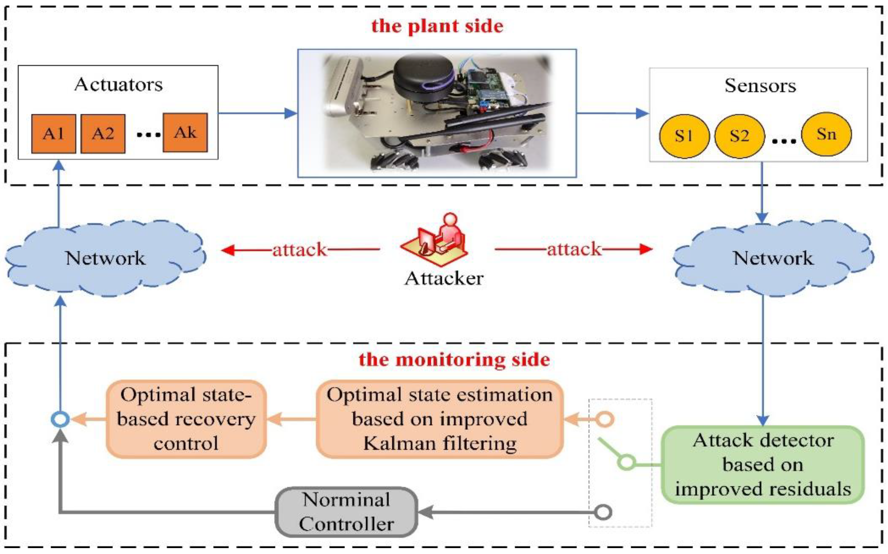
In the security defense problem of CPS, it is the goal to ensure that the system can continue to maintain the normal operation state even after an attack. Therefore, after detecting an attack using the detection method in Section II and performing attack isolation and system state estimation according to the method in Section III, the next step is to implement recovery control for the system based on the above results. This section introduces an optimal state-based recovery control strategy and summarizes the attack detection, attack isolation, state estimation and recovery control comprehensively to give a complete framework of the CPS security protection process, as shown in Figure 3.
Figure 3. The security defense process of CPS that includes attack detection, secure state estimation, and recovery control.
Preprints 86336 g003
In control systems, many control objectives are to enable the system to stably track the reference input to achieve the control requirements. The internal model control (IMC) has a very wide range of applications in the control field as a way to enable the system to track the reference input asymptotically with zero steady-state error. For the recovery control problem of CPS under attacks, this paper introduces an integration link of the reference input signal by combining IMC with the optimal state to achieve the stable operation of the attacked system according to the target command.
Assume that the reference input signal γ ( k ) is generated by the following model.
γ ( k ) = x γ γ ˙ ( k ) = 0
Also, define the tracking error e ( k ) :
e ( k ) = y a ( k ) γ ( k )
Then, the state space can be extended as follows.
e ( k + 1 ) z ( k + 1 ) = 0 C 0 A e ( k ) z ( k ) + 0 B u ( k ) u ( k 1 )
where, z ( k ) denotes the difference of the state variable x ( k ) , i.e., z ( k ) = x ( k ) x ( k 1 ) .
If the system shown in (32) is controllable, then a set of feedback control signals can be designed to make the system stable, i.e.
u ( k ) u ( k 1 ) = F 1 F 2 e ( k ) z ( k )
This means that the tracking error e ( k ) is stable. Therefore, the system is then able to track the reference input signal with zero steady-state error. Integrating (33), the feedback control signal inside the system is obtained as:
u ( k ) = F 1 i = 1 k e ( k ) F 2 x ( k )
Since the state x ( k ) of the system cannot be obtained directly, the optimal state estimate x ^ ( k | k ) is obtained by an improved Kalman filtering method and used to replace the true state x ( k ) in (34).

4. Simulation Results

In this section, a practical simulation is carried out to demonstrate the effectiveness of the proposed optimal state estimation method and recovery control strategy.

4.1. Simulation Setup

Consider a 4-wheeled Omnidirectional Mobile Robot (OMR) with the system parameters shown below:
A = 0.1759 8.0754 × 10 4 0.0000 8.0754 × 10 4 0.1759 0.0000 0.0000 0.0000 0.0675 ,   B = 0.0299 0.0299 0.0299 0.0299 0.0299 0.0299 0.0299 0.0299 0.0887 0.0887 0.0887 0.0887
It is assumed that the mobile robot contains three independent sensors, each of which can independently measure partial or complete state information. So, the matrix of system output parameters corresponding to each sensor is given as:
C s 1 = 0.9 0 0 0 0.9 0 0 0 0.9   , C s 2 = 0.8 0 0 0 0.8 0 0 0 0.8   , C s 3 = 0.6 0 0 0 0.6 0 0 0 0.6
The state variables x = x ˙ , y ˙ , θ ˙ T of the OMR are the X-axis and Y-axis travel velocity and rotation angular velocity in the robot coordinate system. The process noise is set to w ( k ) N ( 0 , 0.001 ) and the measurement noise of the three sensors is set to v 1 ( k ) N ( 0 , 0.008 ) , v 2 ( k ) N ( 0 , 0.005 ) and v 3 ( k ) N ( 0 , 0.003 ) respectively.
In the recovery control, the feedback matrix of (34) is set to:
F = F 1 F 2 = 0.8721 0.8356 0.2802 0.8660 0.8306 0.2839 0.8760 0.8369 0.2956 0.8700 0.8293 0.2919 4.5969 4.4453 1.8020 4.5894 4.4127 1.8089 4.6138 4.4478 1.8594 4.6064 4.4102 1.8526
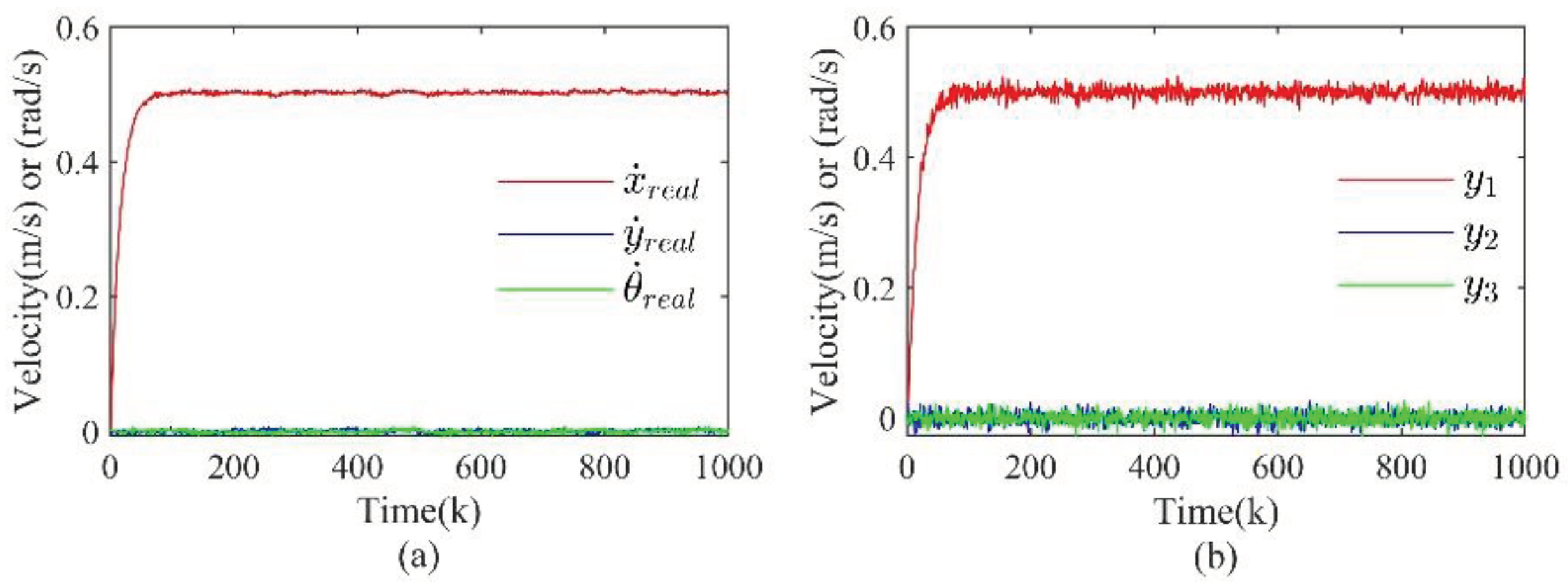
On the monitoring side, the expected movement strategy is set to drive forward in a straight line with a speed of x ˙ ( k ) = 0.5 from the initial state x ( k ) = 0 , 0 , 0 T , during which the output of the sensor s 1 is mainly used, i.e., the sensor fusion module is set to: Φ y s 1 , a | y s 2 , a | y s 3 , a = 0.9 y s 1 , a + 0.05 y s 2 , a + 0.05 y s 3 , a . Without considering the attack, the normal state of the mobile robot is shown in Figure 4.
Figure 4. The normal state and fused measurement output of the OMR when no attack is added. (a) is the normal state; (b) is the fused measurement output.
Preprints 86336 g004
Remark 4.
In all figures of this paper, the asterisk superscript (i.e., *) indicates that the results obtained using the method proposed in this paper. In contrast, the absence of the asterisk superscript indicates that the results obtained by the method proposed in this paper were not used.

4.2. Results Discussion

4.2.1. Zero-dynamics Attack

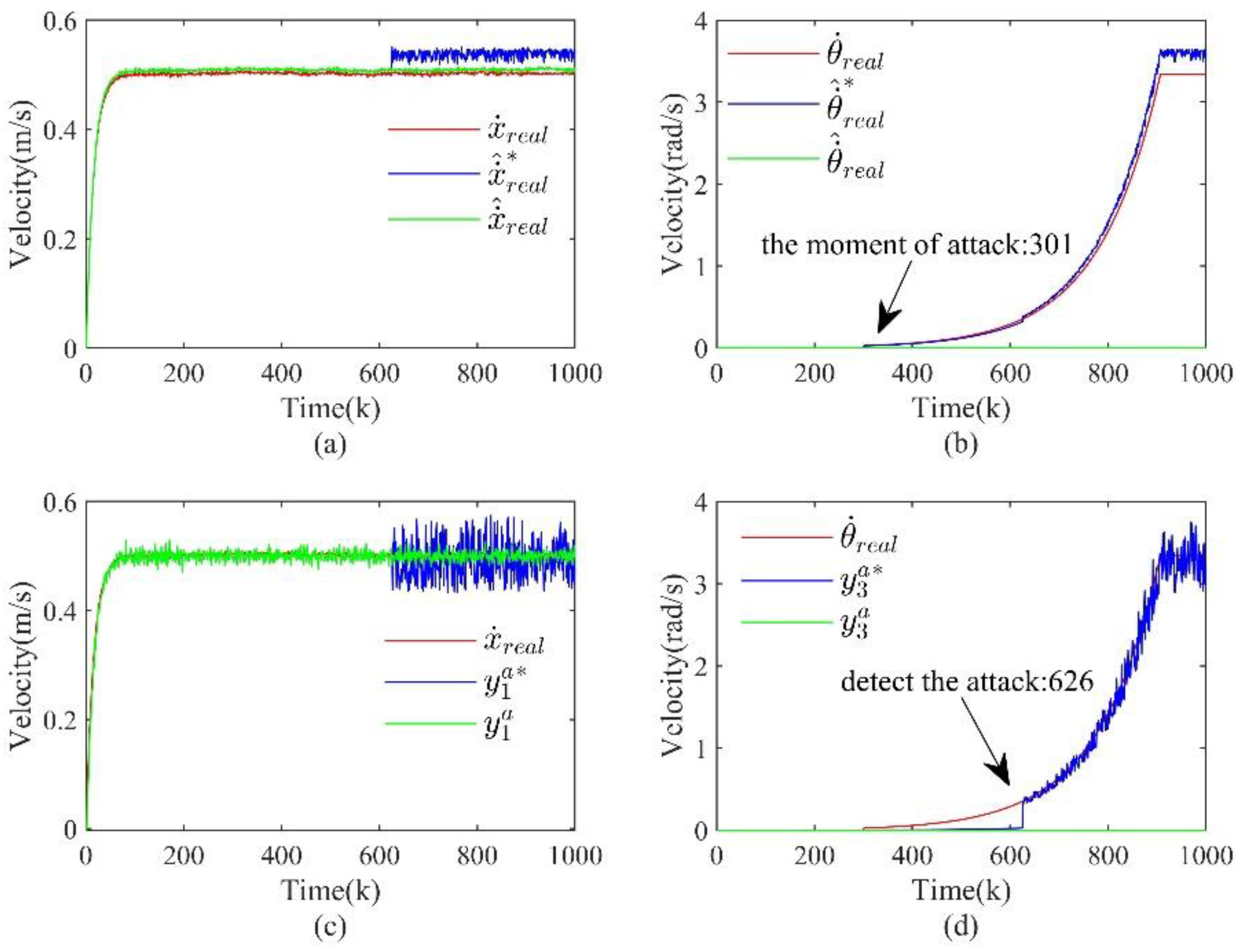
Zero-dynamics attack is mainly stealthy by designing the attack signal a u ( k ) , and there is no direct attack signal to attack the measurement channels. Therefore, in the simulation, the measurement output matrix C s 1 of the sensor s 1 is used to solve (5) and assume that the sensor s 1 does not have access to the rotational state information. The parameters related to the zero-dynamics attack design in (5) are calculated as follows and injected into the actuation channels at k > 300 .
υ = 1.008 , g = 0.0803 ; 0.0803 ; 0.0803 ; 0.0803
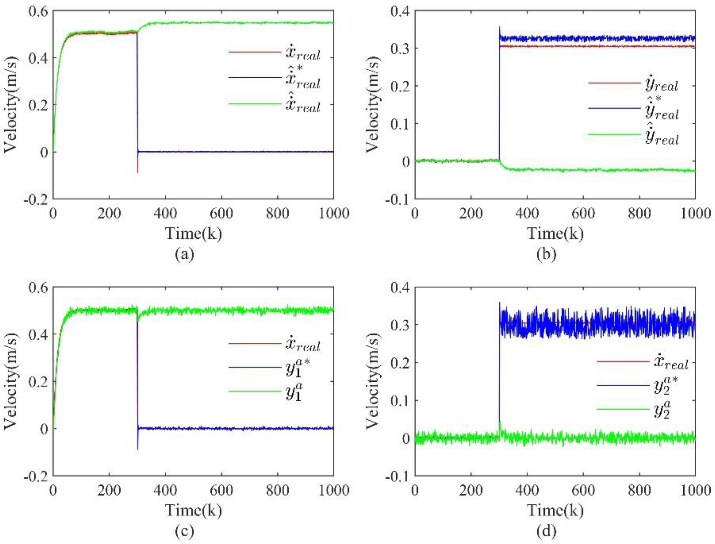
The real state, estimated state, and fused measurement output of the OMR with and without taking the proposed approach in this paper after the injection attack are given in Figure 5. From Figure 5(b) and Figure 5(d), it can be found that the real state of the OMR can be basically estimated using the method proposed in this paper, and the fused measurement output can also show the real state of the system very well.
Figure 5. The real state, estimated state, and fused measured output of the OMR with and without taking the proposed approach in this paper after the injection attack. (a) is the real state and estimated state of the X-axis velocity; (b) is the real state and estimated state of the rotation angular velocity; (c) is the fused measurement output of the X-axis velocity; (d) is the fused measurement output of the rotation angular velocity.
Preprints 86336 g005
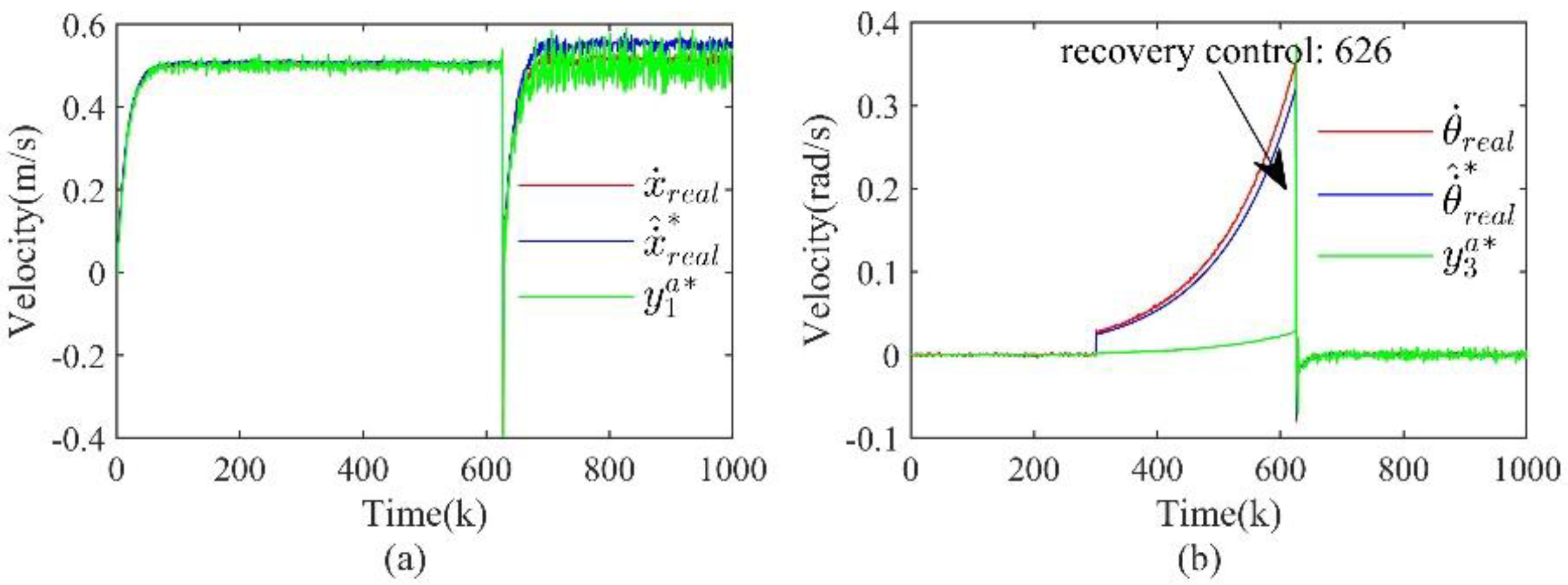
After detecting the attack and estimating the correct state of the OMR, recovery control is introduced, as shown in Figure 6, which shows the system after adding recovery control. From the figure, by taking recovery control, the rotation angular velocity of the OMR can be adjusted so that it will no longer rotate.
Figure 6. The situation of the OMR after adding recovery control. (a) is the situation of the X-axis velocity; (b) is the situation of the rotation angular velocity.
Preprints 86336 g006

4.2.2. Covert Attack

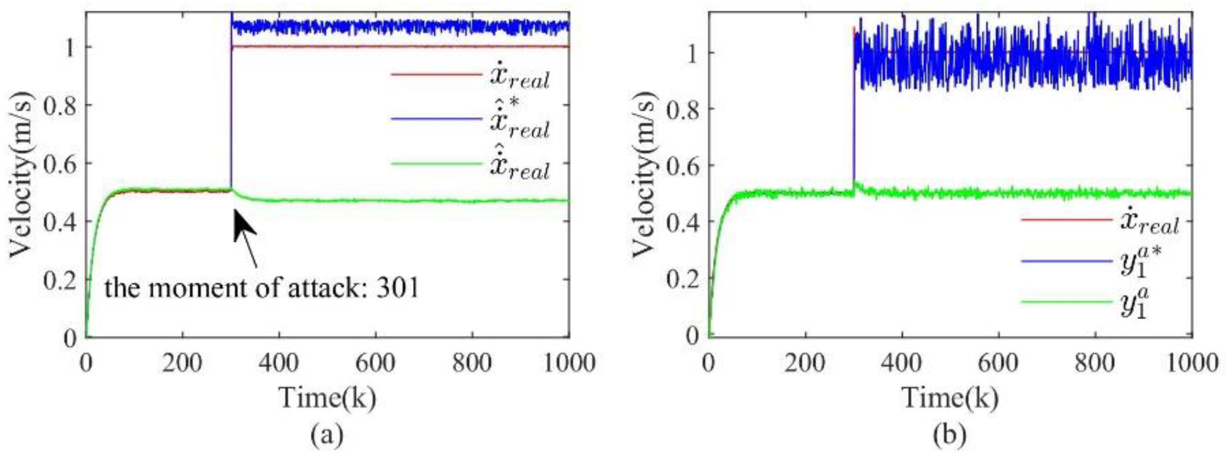
The main purpose of the covert attack is the attack on the actuation channels. Therefore, at the simulation moment k > 300 , the attack target is set to x a ( k ) = 1 , 0 , 0 T , i.e., after injecting the attack, the resulting state of the OMR is straight ahead with a speed of 1m/s. Also, to satisfy the stealthy condition, the attack signal is added to the sensor s 1 according to (6) without attacking the other two sensors.
The real state, estimated state, and fused measurement output of the OMR with and without taking the proposed approach in this paper after the injection attack are given in Figure 7. From Figure 7(a), it is found that a better estimation of the system state can be achieved when the state of the OMR is estimated by adopting the method proposed in this paper. In this case, the actual state is 1m/s, while the average value of the estimated state is 1.07m/s. In addition, Figure 7(b) also demonstrates that the fused measurement output after detection is also valid.
Figure 7. The real state, estimated state, and fused measured output of the OMR with and without taking the proposed approach in this paper after the injection attack. (a) is the real state and estimated state of the X-axis velocity; (b) is the fused measurement output of the X-axis velocity.
Preprints 86336 g007
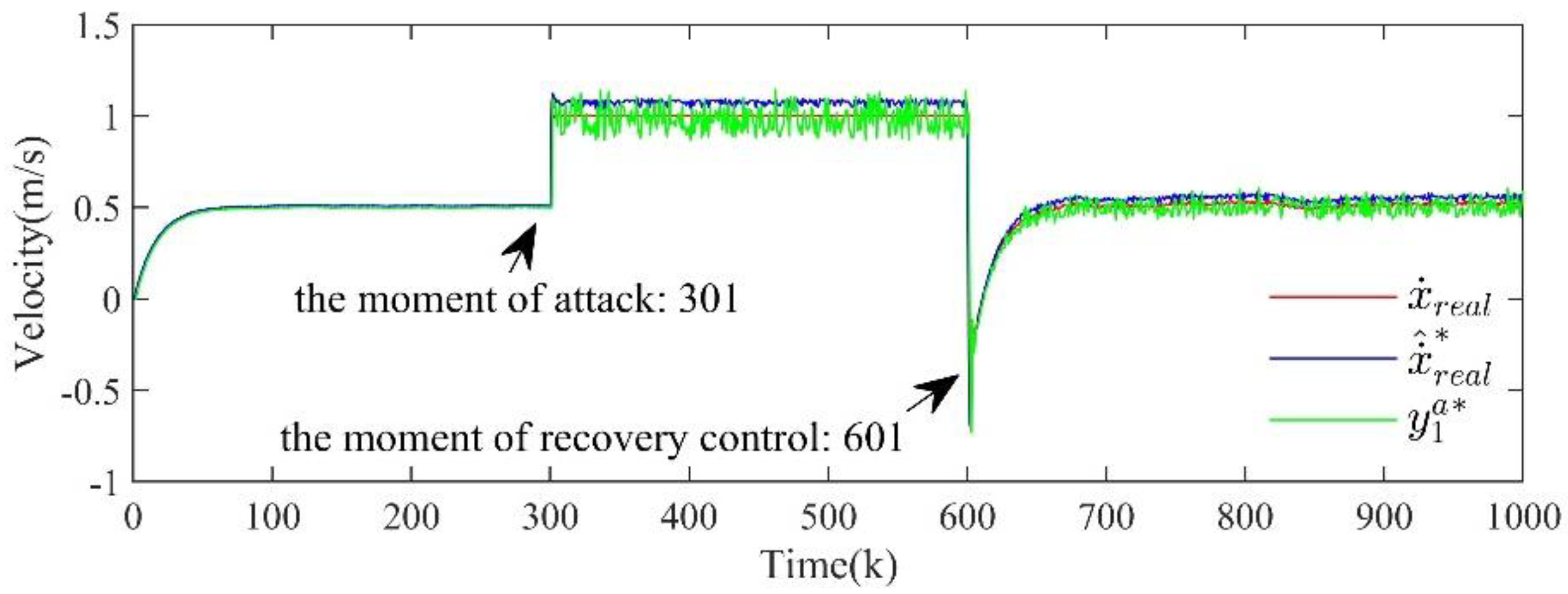
Figure 8 illustrates the change of the system state after taking recovery control at k > 600 . The results show that the OMR can restore the normal driving state by adopting the recovery control strategy.
Figure 8. The change of the system state after taking recovery control.
Preprints 86336 g008

4.2.3. Replay Attack

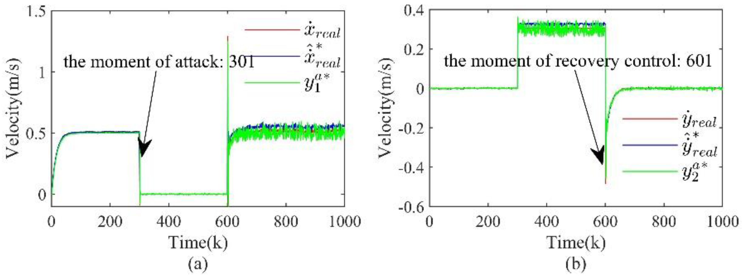
According to the production conditions of the replay attack, the attacked sensor is s 1 , the target x a ( k ) = 0 , 0.3 , 0 T . The attack strategy is described as follows: collect the output data of the sensor s 1 for 100 < k < 300 , inject the attack at k > 300 , continuously overwrite the output data of the sensor s 1 with the previously collected data, and simultaneously calculate a u ( k ) injected into the actuation channels according to the attack target x a ( k ) .
Figure 9. The real state, estimated state, and fused measured output of the OMR with and without taking the proposed approach in this paper after the injection attack. (a) is the real state and estimated state of the X-axis velocity; (b) is the real state and estimated state of the Y-axis velocity; (c) is the fused measurement output of the X-axis velocity; (d) is the fused measurement output of the Y-axis velocity.
Preprints 86336 g009
Figure 10. The situation of the OMR after adding recovery control. (a) is the situation of the X-axis velocity; (b) is the situation of the Y-axis velocity.
Preprints 86336 g010
The real state, estimated state, and fused measurement output of the OMR with and without taking the proposed approach in this paper after the injection attack are given in Figure 9. Figure 10 illustrates the change of the system state after taking recovery control at k > 600 . The results show that the OMR can restore the normal driving state by adopting the recovery control strategy.

5. Conclusions

In this paper, a complete set of security defense processes including attack detection, secure state estimation and recovery control is proposed for the security defense of CPS, which is of great importance for the security defense of CPS. Firstly, by analyzing the structural characteristics of CPS, a state-space model including sensor attack, actuator attack and process attack is established, and three kinds of stealthy attacks are described. Then, the existing attack detection method based on improved residuals is used to detect the stealthy attacks, and based on the detection results, an optimal state estimation method based on improved Kalman filtering is proposed, which can well achieve the estimation of the actual state of the system. Finally, based on the optimal state, the internal model control is introduced to realize the recovery control of the system. Through simulation verification, it can be found that the proposed methods in this paper have better results in both secure state estimation and recovery control.

Author Contributions

Conceptualization, Liang Xin, Biao Yang and Zhiqiang Long; Data curation, Biao Yang; Formal analysis, Liang Xin; Funding acquisition, Zhiqiang Long; Methodology, Biao Yang, Liang Xin and Zhiqiang Long; Writing – original draft, Biao Yang; Writing – review & editing, Biao Yang, Liang Xin and Zhiqiang Long.

Conflicts of Interest

The authors declare no conflict of interest.

References

  1. Y. Ashibani and Q. H. Mahmoud, "Cyber physical systems security: Analysis, challenges and solutions," COMPUT SECUR, vol. 68, pp.81-97,2017.
  2. J. Yaacoub, O. Salman and H. N. Noura et al., "Cyber-physical systems security: Limitations, issues and future trends," MICROPROCESS MICROSY, vol. 77,2020.
  3. Humayed, J. Q. Lin, F. J. Li et al., "Cyber-Physical Systems Security-A Survey," IEEE INTERNET THINGS, vol. 4, no. 6, pp.1802-1831,2017.
  4. A. Wright. On Sapphire and type-safe languages. New York: ACM, 2003: 120. [CrossRef]
  5. P. Y., L. T. and L. J. et al. Cyber-physical System Risk Assessment. 2013 Ninth International Conference on Intelligent Information Hiding and Multimedia Signal Processing. 2013: 442-447.
  6. Adams, "Learning the lessons of WannaCry," Computer Fraud & Security, vol. 2018, no. 9, pp.6-9,2018. [CrossRef]
  7. L. C., G. L. and L. J. et al., "Mimosa: Protecting Private Keys Against Memory Disclosure Attacks Using Hardware Transactional Memory," IEEE T DEPEND SECURE, vol. 18, no. 3, pp.1196-1213,2021.
  8. J. Rubio-Hernan, L. De Cicco and J. Garcia-Alfaro, "On the use of watermark-based schemes to detect cyber-physical attacks.," EURASIP Journal on Information Security, vol. 2017, no. 1, pp.1-25,2017. [CrossRef]
  9. N. V. Patil, C. R. Krishna and K. Kumar, "Distributed frameworks for detecting distributed denial of service attacks: A comprehensive review, challenges and future directions," Concurrency and Computation: Practice and Experience, no. No.10, pp. e6197,2021.
  10. S. M. Dibaji, M. Pirani and D. B. Flamholz et al., "A systems and control perspective of CPS security," ANNU REV CONTROL, vol. 47, pp.394-411,2019. [CrossRef]
  11. M. Ghaderi, K. Gheitasi and W. Lucia, "A Blended Active Detection Strategy for False Data Injection Attacks in Cyber-Physical Systems," IEEE Transactions on Control of Network Systems, vol. 8, no. 1, pp.168-176,2021. [CrossRef]
  12. G. P., W. S. and S. B., "A Moving Target Defense for Securing Cyber-Physical Systems," IEEE T AUTOMAT CONTR, vol. 66, no. 5, pp.2016-2031,2021.
  13. G. M., G. K. and L. W. A Novel Control Architecture for the Detection of False Data Injection Attacks in Networked Control Systems. 2019 American Control Conference (ACC). 2019: 139-144.
  14. N. F. N. Forti, G. B. G. Battistelli, L. C. L. Chisci et al., "A Bayesian approach to joint attack detection and resilient state estimation," 2016 IEEE 55TH CONFERENCE ON DECISION AND CONTROL (CDC), pp.1192-1198,2016.
  15. K. Zhang, B. Jiang, S. X. Ding et al., "Robust Asymptotic Fault Estimation of Discrete-Time Interconnected Systems With Sensor Faults," IEEE T CYBERNETICS, vol. 52, no. 3, pp.1691-1700,2022. [CrossRef]
  16. H. Yang, S. Yin, H. Han et al., "Sparse Actuator and Sensor Attacks Reconstruction for Linear Cyber-Physical Systems With Sliding Mode Observer," IEEE T IND INFORM, vol. 18, no. 6, pp.3873-3884,2022. [CrossRef]
  17. J. C. Chen and Y. Shi, "Stochastic model predictive control framework for resilient cyber-physical systems: review and perspectives," PHILOS T R SOC A, vol. 379, no. 2207,2021. [CrossRef]
  18. H. Ge, D. Yue, X. P. Xie et al., "A unified modeling of muti-sources cyber-attacks with uncertainties for CPS security control," J FRANKLIN I, vol. 358, no. 1, pp.89-113,2021. [CrossRef]
  19. Z. Wang, B. Zhang, X. Xu et al., "Research on cyber-physical system control strategy under false data injection attack perception.," Transactions of the Institute of Measurement & Control, vol., pp.1,2022. [CrossRef]
  20. S. X. Ding, L. Li, D. Zhao et al., "Application of the unified control and detection framework to detecting stealthy integrity cyber-attacks on feedback control systems,",2021. [CrossRef]
  21. A. Teixeira, I. Shames, H. Sandberg et al., "A secure control framework for resource-limited adversaries," AUTOMATICA, vol. 51, pp.135-148,2015. [CrossRef]
  22. S. S. R., "Covert Misappropriation of Networked Control Systems: Presenting a Feedback Structure," IEEE CONTR SYST MAG, vol. 35, no. 1, pp.82-92,2015.
  23. M. Y. and S. B. Secure control against replay attacks. 2009 47th Annual Allerton Conference on Communication, Control, and Computing (Allerton). 2009: 911-918.
Disclaimer/Publisher’s Note: The statements, opinions and data contained in all publications are solely those of the individual author(s) and contributor(s) and not of MDPI and/or the editor(s). MDPI and/or the editor(s) disclaim responsibility for any injury to people or property resulting from any ideas, methods, instructions or products referred to in the content.
Copyright: This open access article is published under a Creative Commons CC BY 4.0 license, which permit the free download, distribution, and reuse, provided that the author and preprint are cited in any reuse.
Prerpints.org logo

Preprints.org is a free preprint server supported by MDPI in Basel, Switzerland.

Subscribe

© 2024 MDPI (Basel, Switzerland) unless otherwise stated