1. Introduction
Among the different classes of Bio Electrochemical Systems, Microbial Fuel Cells (MFCs) and Microbial Electrolysis Cells (MECs) received great attention in the ever-growing context of sustainable energy production. The crucial feature of both MFCs and MECs systems can be identified in the anode electrode, on which an electroactive biofilm must develop [
1,
2,
3]. The electrical activity of the biofilm plays a key role in defining performances of both the Bio Electrochemical devices. Indeed, electroactive biofilms show the ability to directly recover the chemical energy, trapped in organic matter known as fuel, into electrical energy, acting as bio-catalyst for the oxidation reaction of fuel [
1,
2,
3,
4,
5,
6,
7,
8,
9,
10,
11,
12,
13].In light of that, several works in the literature focused their attention on the design and fabrication of anode electrodes, implementing different strategies to improve the electrodes’ surface properties in terms of hydrophilicity, porosity and electrical conductivity [
4,
5,
6,
7,
8,
9,
10,
11,
12,
13]. Indeed, it is widely acknowledged that there is a direct correlation between the surface area of the anode electrode, biofilm formation and growth and the consequent optimisation of device performance [
10,
14,
15,
16]. With the main aim of coupling the ability to improving anode’s electrical conductivity and while preserving its inherent continuous porosity, many works in the literature propose the deposition of poly(3,4-ethylene-dioxy-thiophene) poly(styrene-sulfonate)(PEDOT:PSS) layer on standard carbon substrates.[
11,
13,
14,
17,
18,
19]. PEDOT:PSS is a well-known intrinsically conductive polymer [
20,
21], successfully applied to a wide range of industrial applications, as biomedicine and energy conversion and storage [
21,
22,
23]. In such applications, PEDOT:PSS represented an ideal choice thanks to its stability in water-based solutions, superior physical-chemical properties, its bio compatibility and non-cytotoxicity and processability through a wide range of deposition techniques [
20,
21]. Introducing PEDOT:PSS in BES offers incredible opportunities to improve the anode performance by coupling the continuous electrical conductivity of this intrinsically conductive polymer to the porosity of standard carbon-based materials, optimizing surfaces to host and sustain electroactive biofilms. To reach this goal several techniques for the processing of PEDOT:PSS where proposed as electrochemical methods [
11,
14,
24,
25] and dip coating [
19]. Such techniques may pose limitations when scaled to large-area electrodes, requiring the use of high-current appliances and large volumes of solution precursors. In the present work, we propose Ultrasonic Spray Coating (USC) technique for the deposition of a nanostructured layer of PEDOT:PSS, able to achieve a uniform coverage of the tri-dimensional surface of carbon electrodes (i.e., carbon paper, CP). The USC technique is based on the dispersion of the spraying ink via high frequency vibrations induced at the spraying nozzle [
26,
27]. It is a versatile technology for fabrication of thin nano-coatings, it can be easily scaled up for deposition on large areas with optimal uniformity and conformity. In addition, USC allows to precisely control the spatial uniformity of the deposited layer and to predetermine the amount of deposited material [
26]. USC has been widely used in fuel cells for the deposition of catalyst materials [
28,
29,
30] and in organic electronics applications [
31] highlighting the potential of USC for the fabrication of smooth and uniform thin films on plain substrates [
27,
31,
32].
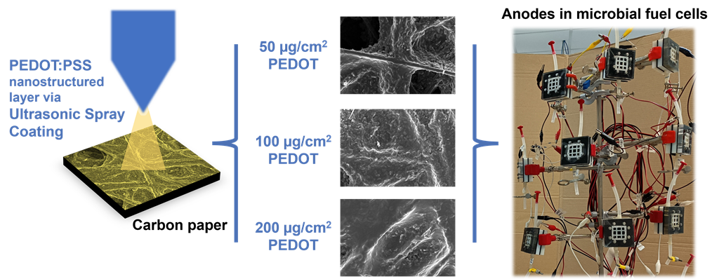
Application of USC as a methodology to improve performances of anodes in Microbial Fuel Cells has been anticipated in our previous work . In the present work, employing USC, we fabricated electrodes on which we then observed the nanostructured morphology and characterized the electrochemical properties provided by such PEDOT:PSS layer. In particular, with the main purpose to verify how the amount of deposited PEDOT can affect the features of anode electrodes, and consequently the overall performance of MFCs, we fabricated anode electrodes by selecting three different PEDOT amounts. The evaluation of the electrochemical active surface area indicated, for the best performing fabricated electrodes, an increase of (2.6 ± 0.2) times compared to bare carbon paper.
In addition, we investigated the use of Raman spectroscopy to quantitatively validate and map the spatial uniformity of such layers. This was possible by correlating the presence of PEDOT:PSS with the intensity of a characteristic Raman peak (1437 cm-1, Cα=Cβ symmetric stretching vibrations inside PEDOT:PSS).
Finally, we assessed performance improvements and stability in laboratory single chamber microbial fuel cell (SCMFC) devices. In terms of energy recovery, SCMFCs featuring the PEDOT:PSS nanostructured layer achieved at best (13 ± 2) J·m−3 , which is approximately three times higher compared to control cells at (4.3 ± 0.5) J·m−3.
2. Materials and Methods
2.1. Anodes Fabrication via Ultrasonic Spray Coating (USC)
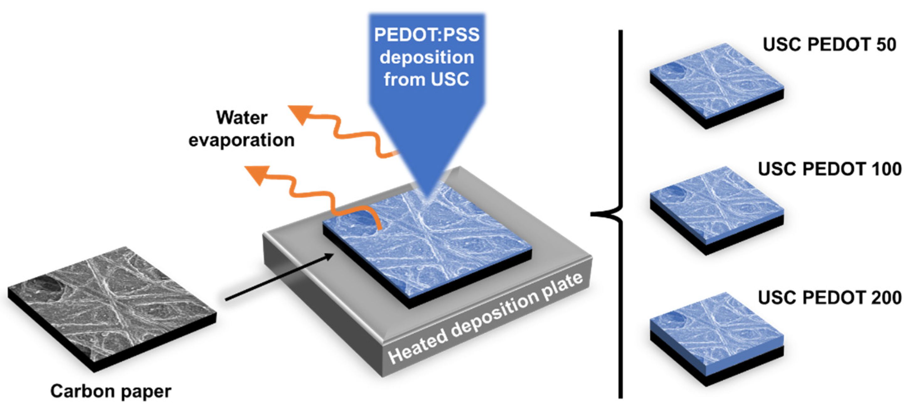
We fabricated all anode electrodes by depositing a PEDOT:PSS nanostructured layer on bare carbon paper employing a Nadetech Ultrasonic Spray Coater (Nadetech Innovations, Spain). A great advantage of this technique is represented by the possibility to directly deposit the nanostructured layer onto carbon paper, ensuring a uniform deposition and a good adhesion, without the usage of other binders.
The fabrication of anode electrodes started from commercial carbon paper (AvCarb, USA), cut in 30x30 mm2 squares and without any pre-treatment. To realize the nanostructured depositions, we prepared spraying solutions for ultrasonic spray coating by mixing poly(3,4-ethylene-dioxy-thiophene) poly(styrene-sulfonate) (PEDOT:PSS, 1.3 wt.% water dispersion, purchased from Sigma Aldrich, Germany), and Milli-Q de-ionized water (Merck Millipore, Germany). Each substrate held in place on the heated deposition plate by a silicone mask and vacuum suction. During the deposition, the spray nozzle followed a pattern chosen to maximize the spatial uniformity of the nanostructured layer. The pattern was repeated multiple times so to achieve the target amount of deposited material, with process duration ranging from 2 to 6 minutes.
As discussed in a previous work [
33], we prepared the spraying solutions by diluting as-purchased PEDOT:PSS aqueous dispersion (0.5 wt.% PEDOT, 0.8 wt.% PSS) in de-ionized water (2:8 volume ratio), obtaining a final solution with 1 mg/mL of PEDOT and 1.6 mg/mL of PSS. We stored the prepared solution at 4°C and prior use we employed magnetic stirring to ensure uniform mixing. This high dilution ensured the possibility to finely modulate the final amount of PEDOT deposited, while also ensuring spatial uniformity.
To obtain a PEDOT:PSS nanostructured layer, different process parameters were defined, such as a flow rate of 20 mL/h, a piezoelectric nozzle operation of 2 W at 88-89 kHz, and a nozzle-to-plate distance of 100 mm. Moreover, a deposition plate temperature of 80°C was defined to so to preserve the distribution uniformity of the final nanostructured layer, by to ensuring the complete evaporation of solvent (water) traces present into the initial polymeric solution.
Previous literature works, describing the deposition of PEDOT:PSS for high performance MFC anodes, found that a suitable amount of such material may range from 20 µg/cm
2 to few hundreds of µg/cm
2 [
11,
19]. In addition, it was highlighted how an excessive quantity of deposited material might increase the internal resistance of the anode, thus resulting detrimental for MFC performances [
11,
17].
With the main purpose of investigating how USC-deposited PEDOT:PSS can affect the performance of anode electrodes, in the present work we fabricated electrodes by depositing a nanostructured PEDOT:PSS layer containing different amounts of PEDOT. As represented in
Figure 1, we realised and compared three different anode electrode conditions:
i) USC PEDOT 50, containing 50 µg/cm
2 of PEDOT;
ii) USC PEDOT 100 made of 100 µg/cm
2 of PEDOT and
iii) USC PEDOT 200 based on 200 µg/cm
2 of PEDOT. All fabricated anode electrodes were directly compared with Carbon paper, a control reference electrode obtained from bare carbon paper. For each deposition target, we produced multiple identical electrodes to verify the reproducibility of the process and to obtain several copies sufficient to perform all the proposed characterization.
2.2. Characterization Techniques
2.2.1. Morphological and Physical-Chemical Characterizations on Electrodes
To perform surface morphology characterization of anode electrodes, we employed a Field Emission Scanning Electron Microscope (FESEM, ZEISS Supra 40, Germany), also featuring a detector for Energy-Dispersive X-ray (EDX) spectroscopy.
Raman spectroscopy (Renishaw InVia Reflex spectrometer, λex = 532 nm) was used to investigate the surface of developed anodes, with a focus on the presence of PEDOT: PSS, leading thus to identify its fingerprint peaks. In addition, through the analysis of Raman spectra acquired at different sites on the electrode’s surface, it was possible to assess the spatial deposition uniformity.
2.2.2. Electrochemical Characterizations on Electrodes
With a view to assessing the performance of fabricated electrodes in their intended environment of use, we performed both electrochemical impedance spectroscopy (EIS) and cyclic voltammetry (CV) in the standard MFCs’ electrolyte solution previously described.
We conducted all electrochemical characterizations using a PalmSens 4 (PalmSens BV, Netherlands) potentiostat. All these characterizations were performed in an electrochemical cell with a three-electrode configuration, where anodes electrodes acted as working electrode, silver/silver chloride (Ag/AgCl) was used as reference electrode and a Pt wire acted as counter electrode. EIS characterizations, which aimed at investigating the interfaces arising at the anode electrode, were obtained by imposing a sinusoidal signal with a 10mV amplitude and a frequency range from 200mHz to 150 kHz. For what concerned CV characterizations, the potential was scanned in the range between –0.5V to 0.9V at a rate of 100 mV/s.
CV characterizations were also performed to quantify the effect on the electrochemical active surface area (EASA) of the PEDOT: PSS nanostructured layer. During this characterization, all fabricated electrodes were immersed in an electrolyte solution containing potassium hexacyanoferrate (1 mM) and sodium sulphate (100 mM). Then, we analysed the CV curves considering the following Equation 1, known as Matsuda’s equation:
where n = 1 is the number of electrons transferred, F ≈ 96485 C·mol
-1 is Faraday’s constant, cr = 10
-3 mol·L-1 is the initial potassium hexacyanoferrate concentration, D = 5.79 · 10
-6 cm
2·s
-1 is the diffusion coefficient of potassium hexacyanoferrate R ≈ 8.314 J·mol
-1·K
-1 is the gas constant, T = 293 K is the electrolyte solution temperature. Also, i
p (A) is the peak current measured from CV curves during the oxidation of potassium hexacyanoferrate and θ (mV·s
-1) is the scan rate employed for the CV acquisition, namely 10, 20, 50 mV·s
-1. Finally, A (cm
2) is the electrochemical active surface area, to be determined.
2.3.3. SCMFCs Fabrication and Electrical and Electrochemical Characterizations
As described in our previous works [
15,
16,
32,
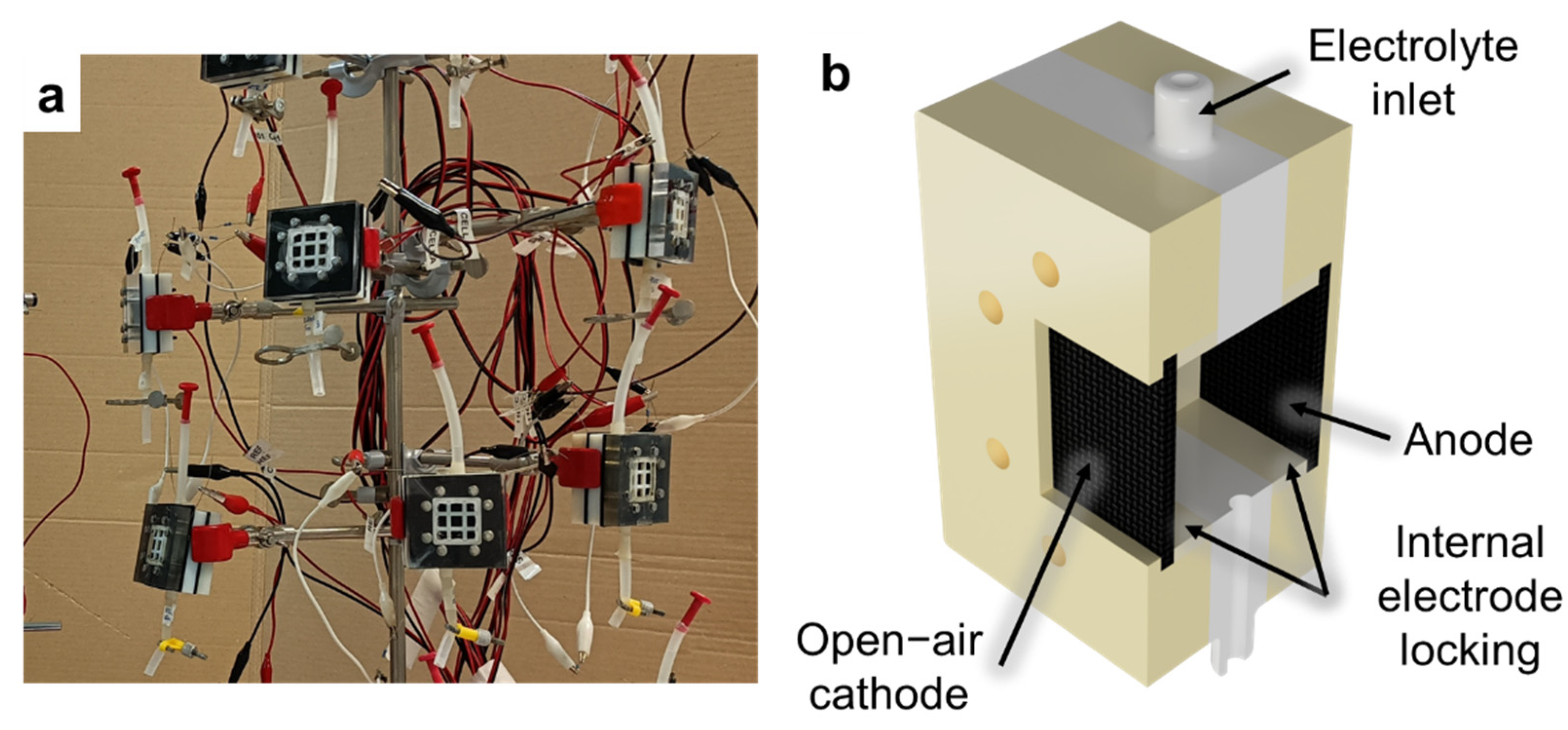
34], open-air cathode Single Chamber Microbial Fuel Cells (SCMFCs) were used (
Figure 2a). These devices present a membrane-less configuration, for which the electrolyte is in common between anode and cathode compartments (
Figure 2b). All fabricated electrodes, USC PEDOT 50, USC PEDOT 100 e USC PEDOT 200 respectively, were employed as anodes in SCMFCs and comparted with the bare carbon paper, acted as control reference. For what concerned the cathode electrodes, we utilised commercial AvCarb Gas Diffusion Systems (purchased from Fuel Cell Store, USA), featuring a poly-tetra-fluoro-ethylene (PTFE) treatment on the air-facing side, and a micro-porous surface coating facing the electrolyte side. To promote direct oxygen reduction reaction (ORR) [
15,
35], we brushed on the micro-porous surface a catalyst paste based on 0.5 mg/cm
2 of platinum (10 wt% on carbon, from Sigma Aldrich) and 3 mg/cm
2 of Nafion (5 wt%, from Sigma Aldrich) acting as a binder [
15,
16,
32]. A fixed distance between anode and cathode electrodes was ensured by an intermediate compartment, holding inlet and outlet holes and an upper aperture for reference electrode insertion. The total internal volume was 12.5 cm
3 and the geometric area of both anode and cathode electrodes was equal to 5.76 cm
2. The cathode and anode electrodes were internally held in place and electrically contacted by 3D printed frames threaded with titanium wire (Goodfellow Cambridge Ltd, UK).
A water-based electrolyte, containing sodium acetate (C2H3NaO2, 1 g/L) as carbon energy source, ammonium chloride (NH4Cl, 0.31 g/L) and potassium chloride (KCl, 0.13 g/L) as nitrogen and minerals source, and sodium di-hydrogen phosphate (NaH2PO4, 2.450 g/L) for pH stability, was used. The electrolyte solution, obtained by dissolving the reagents in de−ionized water, was autoclaved prior to use. All these reagents were purchased from Sigma Aldrich.
A multichannel data acquisition unit (Keysight 34970A, Agilent Technologies, USA) was used to monitor the output voltage for all SCMFCs, evaluating thus the overall devices’ performance. We conducted all experiments, one for each deposition condition, in a triplicate mode.
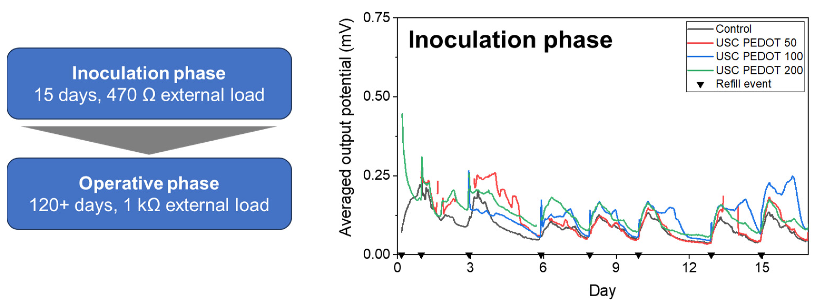
Initially, we inoculated the MFCs with a mixed microbial consortium derived from marine sediment collected in La Spezia (Italy). We obtained the inoculum by mixing marine sediment to the previously described sodium-acetate-based solution. We stored the inoculum on an oscillating plate at ambient temperature and prepared the refills solution by mixing the last used inoculum with standard sodium-acetate electrolyte at a 1:10 volume ratio. After 8 refills with inoculum medium spanning over a 15-days period, the MFCs reached a stable potential output. Then, cells switched to the operative phase, lasted approximately 4 months, during which the inoculum medium was replaced by standard sodium acetate-based electrolyte [
15,
16].
In agreement with what discussed in previous works [
15,
16], during the inoculation phase of the MFCs we applied to each cell an external load of 470 Ω in order to promote the biofilm formation on the anode electrode. Later, during the operative period of the MFCs, we raised the external load to its final value of 1 kΩ.
Energy recovery parameters [
3,
15,38] were introduced to accurately correlate the MFCs’ performance improvements with the presence of nanostructured PEDOT:PSS layer onto anode surface. As reported in different works of the literature [
3,
15,38], starting from the measured output potential, we also computed the average energy recover parameter, defined by the following Equation 2:
where E
rec (J·m
−3) is the Energy Recovery,
(J) is the integral of the recovered energy between the initial (t
1) and final (t
2) moments associated to each refill and V
int (m
3) is the cell’s internal volume [
3,
15,36].
Throughout the whole experiment, we also performed Electrochemical Impedance Spectroscopy (EIS) characterizations to investigate the interfaces arising inside the cells at the anode electrode, and Linear Sweep Voltammetry (LSV) to assess overall performances of SCMFCs. For EIS, we employed both a two-electrodes and a three-electrodes setup by imposing an AC sinusoidal signal with 10 mV amplitude and frequency ranging from 200 mHz to 150 kHz. For LSV, we employed a two-electrodes configuration to sweep the anodic potential from open-circuit voltage (OCV) to short-circuit voltage (0 V) at a scan rate of 0.1 V·s-1. In all configurations, the anode acted as working electrode and the cathode as counter electrode. The reference electrode was either connected to the cathode in two-electrodes mode, or to an Ag/AgCl electrode in three-electrodes mode. We conducted EIS characterizations in open circuit condition.
3. Results and Discussion
3.1. Morphological and Physical-Chemical Characterizations
3.1.1. FESEM Characterization on Electrodes
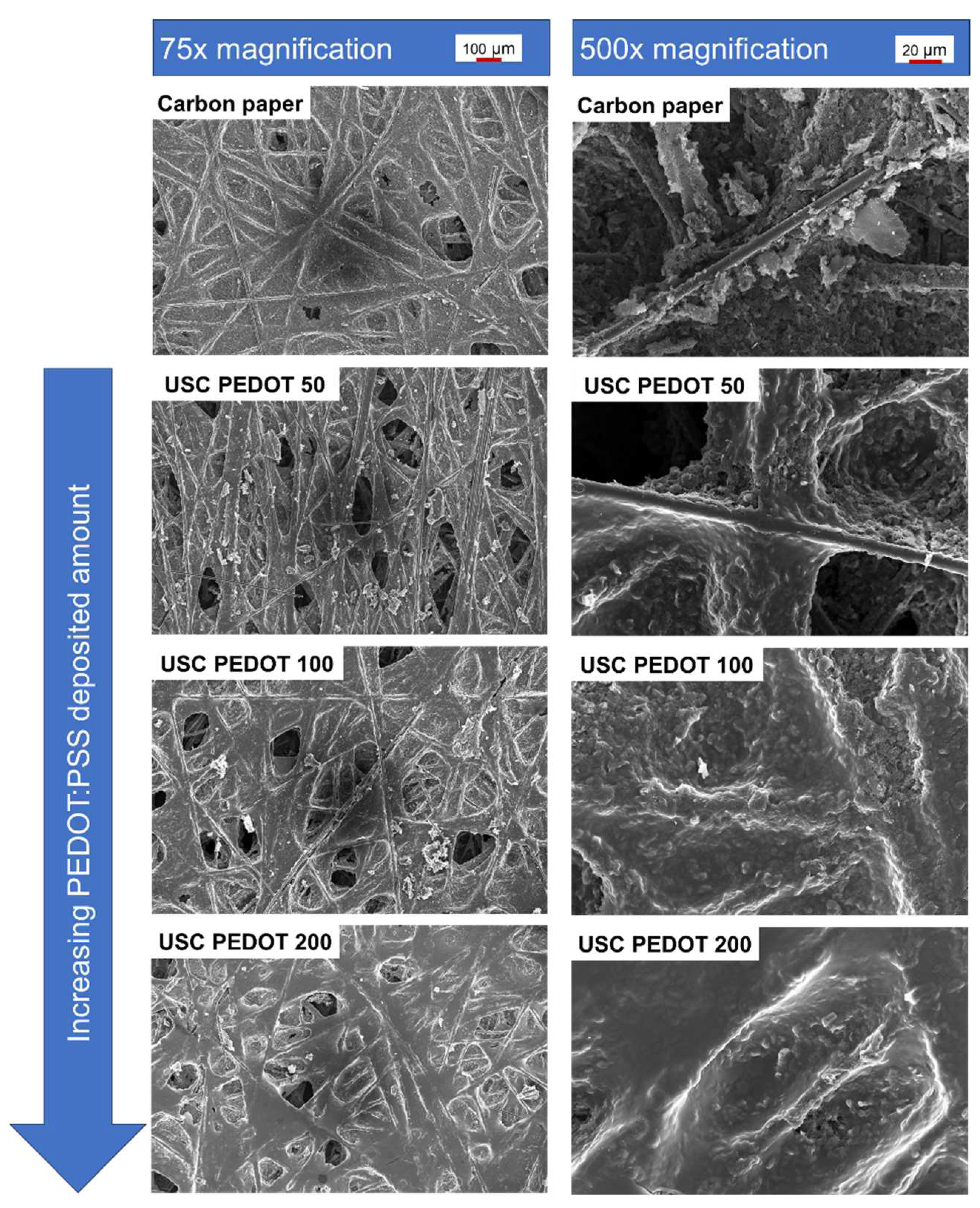
We compared the surface morphology of fabricated electrodes respect to as-purchased bare carbon paper (
Figure 3). As the deposited material amount increased, the PEDOT:PSS nanostructured layer became smoother and more uniformly distributed over the surface. Observing the evolution from 50 µg/cm
2 (USC PEDOT 50) to 100 µg/cm
2 (USC PEDOT 100) and finally 200 µg/cm
2 (USC PEDOT 200) of deposited PEDOT, it is interesting to notice how the deposited material preferentially accumulated around protruding superficial fibres before the rest of the available surface. Nonetheless, the deposited layer covered the carbon-based substrate while preserving the features of the underlying superficial nanostructures.
3.1.2. Physical-Chemical Characterizations
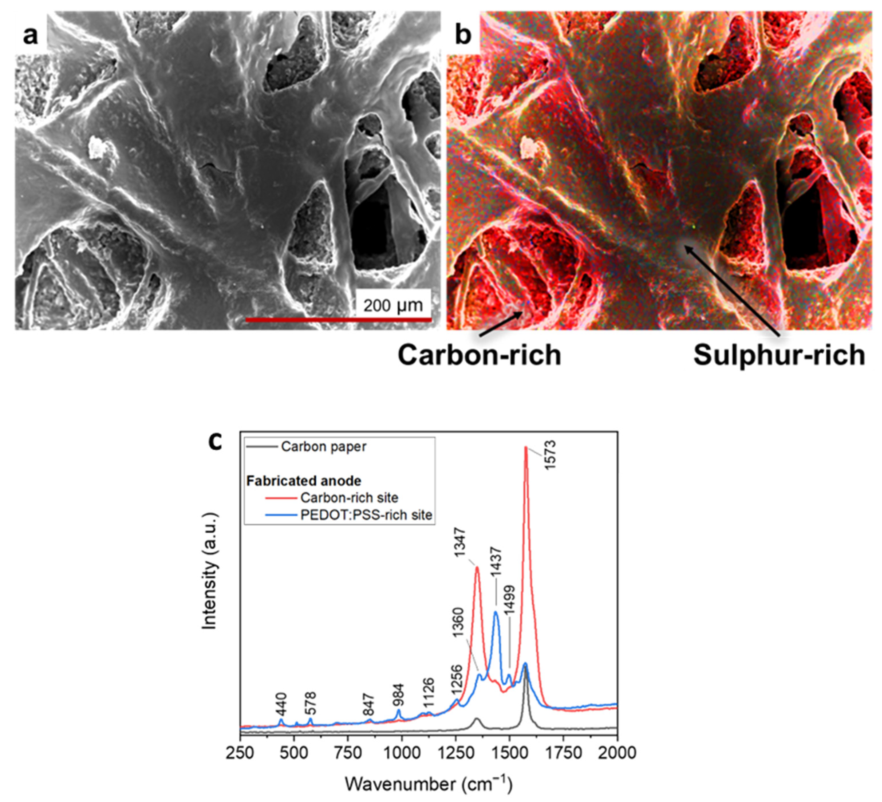
With the main aim to confirm that the nanostructured layer present on the electrodes’ surface was originated by the conformal deposition of PEDOT:PSS, FESEM-EDX characterizations and Raman spectroscopy were implemented.
Figure 4a-b led to demonstrate that the features of nanostructured layers, adhered onto carbon backbone, were due to the presence of PEDOT:PSS. Indeed, traces of elemental sulphur, associated to PEDOT:PSS, were predominantly detected in correspondence with the uniform layers deposited after the USC process, in contrast to the porous areas characterised by the greater presence of carbon, typical of carbon paper. With the aim of confirming and complementing the results obtained by performing EDX measurements, we performed Raman analyses of fabricated electrodes’ surface.
The reference Raman spectrum of bare carbon paper, displays the two peaks characteristic of carbon-based materials: D band (around 1347 cm
−1), related to the presence of defects, vacancies and bent sp
2 bonds in the graphitic structure, and G band (around 1573 cm
−1), associated with in-plane vibration of sp
2 hybridized C-C bonds, as highlighted by red curve in
Figure 4c.
Analysing the red and blue curves in
Figure 4c, it was possible to appreciate Raman spectra acquired on a USC PEDOT 200 anode, where a series of additional peaks overlap with those associated to carbon paper. The highest intensity peaks, located at 1256, 1360, and 1437 cm
−1, can be linked to PEDOT:PSS present on top of the carbon paper substrate. Such peaks can be associated, respectively, to Cα–Cα′ inter-ring stretching, Cβ–Cβ′ stretching, and Cα=Cβ symmetric stretching vibrations [
14,37]. Other weaker intensity peaks are also compatible with the presence of PEDOT:PSS, in agreement with those identified by Kong et al. [37].
EDX analysis and RAMAN spectroscopy offer the evidence of the effectiveness of USC to fabricate nanocoatings able to precisely cover complex surfaces with tri dimensional features at the micro and nanoscale. Indeed the results of
Figure 4 confirm that the changes of the surface morphology of the electrodes are only related to the PEDOT:PSS coating and clearly demonstrate that the key features of carbon-paper electrodes are well reproduced.
3.2. Electrochemical Characterization on Electrodes
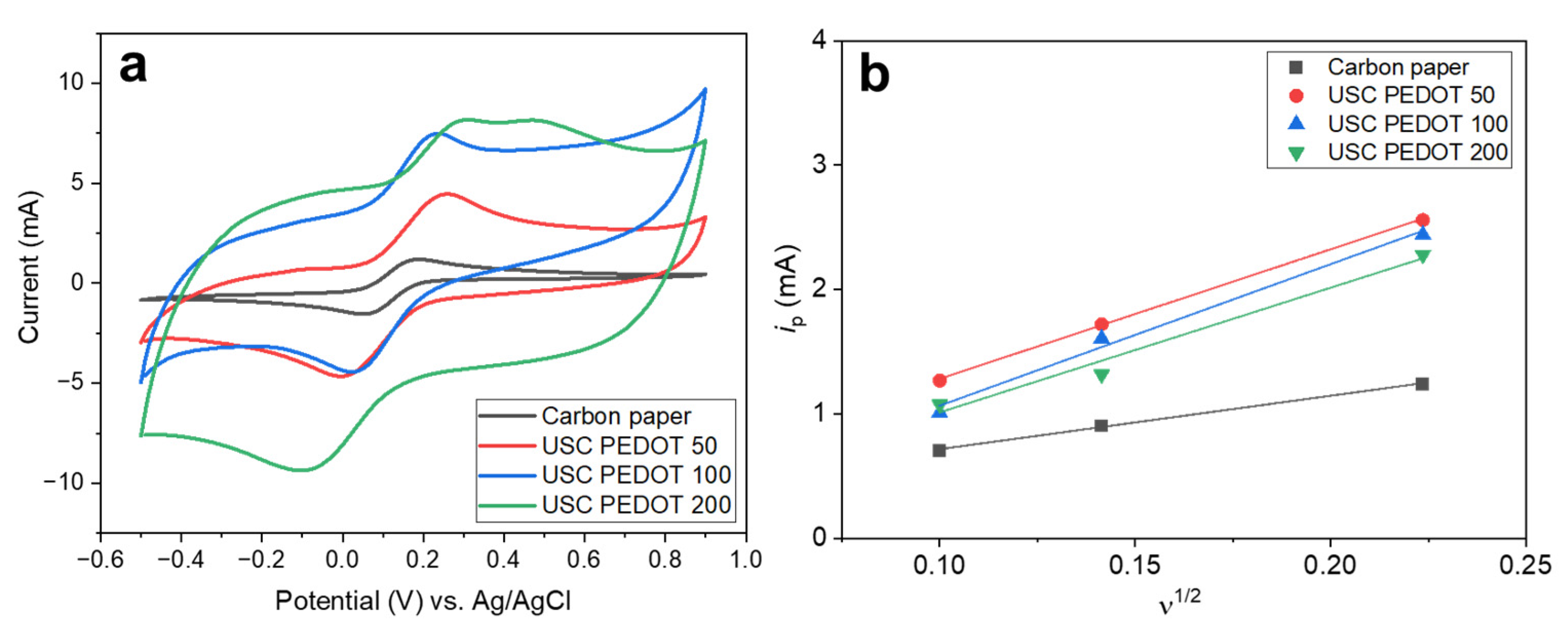
Figure 5a reports cyclic voltammograms obtained for all fabricated electrodes in hexacyanoferrate electrolyte solution. Comparing these curves, it is possible to perform a rough estimation of the Electric Double Layer Capacitance (EDLC) inside the electrochemical cell. Indeed, the potential sweep during CV measurements induces an accumulation of charges at the electrode-electrolyte interface, giving rise to such EDLC. The currents observed during forward and backward scans, related to the charge/discharge processes of the EDLC, for a given scan rate can be correlated to the capacity of the EDLC itself.
Turns out, the higher is the amount of PEDOT:PSS, the greater is the maximum current achieved and so the EDLC value. As a matter of fact, EDLC values could be influenced by the presence of hydrophilic PSS, whose amount also increased linearly with that of PEDOT into the nanostructured layer. It is recognised how PSS is responsible for the increase of surfaces’ wettability and the electrochemical active surface area [
14,38].
Moreover, it was possible to highlight how USC PEDOT anodes featured a sharper hexacyanoferrate reduction peak respect to bare carbon paper, indicating an improved electrocatalytic properties of USC PEDOT 50, USC PEDOT 100 and USC PEDOT 200.
To better estimate the electrochemical activity of the nanostructured layer obtained by USC, we calculated from CVs the electrochemical active surface area (EASA). We applied Equation 1 to all the anode electrodes, considering the values of the current i
p observed at each scan rate (
Figure 5b). The values of i
p current, plotted as function of the square root of scan rate, provided the EASA values listed in
Table 1.
As summarized in
Table 1, the results determined, confirming that all USC PEDOT anode electrodes provided an increase in EASA with respect to the bare carbon paper. The EASA value obtained for the best performing electrode, i.e. USC PEDOT 100 is (2.6 ± 0.2) times higher than the value obtained for bare carbon paper. In particular, EASA of USC PEDOT 50, close to (15.9 ± 0.3) cm
2, is three times higher than EASA value for carbon paper, equal to (6.6 ± 0.3) cm
2. USC PEDOT 100 ensured a slight improvement of EASA, achieving a value equal to (17 ± 2) cm
2, while, on the contrary, USC PEDOT 200 is characterised by a slightly lower electrochemically active area. This result can be explained considering the significantly higher EDLC of USC PEDOT 200 samples, which might negatively affect the electrochemical active area of the electrode itself.
3.3. Electrodes Operation in MFCs
3.3.1. MFC output Potential Monitoring
Figure 6 reports the average potential output, generated by each MFCs triplet during this initial inoculation phase. All results allowed to confirm the successful biofilm growth on all anode electrodes’ surface, providing a stable voltage trend already after one week from the beginning of the experiment. In particular, it was possible to highlight how the presence of the PEDOT:PSS nanostructured layer onto anodes’ surface positively affected the biofilm formation.
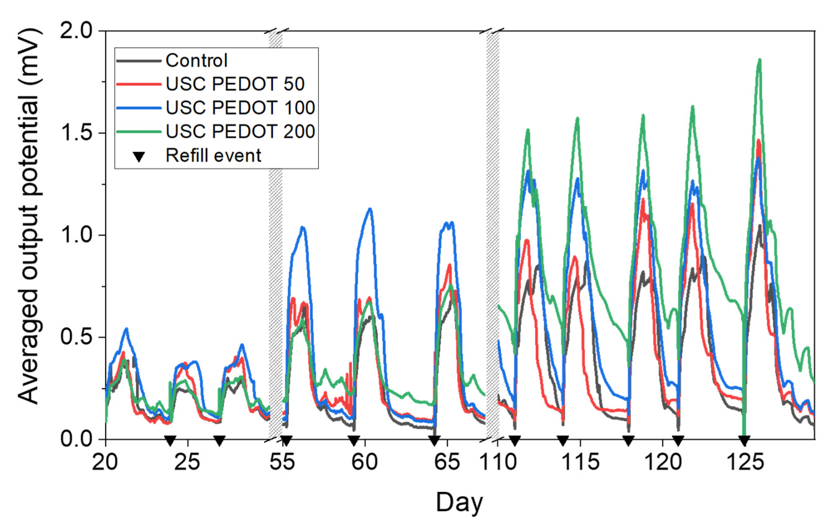
The overall performance of each MFCs were represented in
Figure 7 in terms of voltage trends versus time. It is possible to observe an improvement of the performance when PEDOT:PSS layers was deposited onto carbon backbone. In particular, MFCs featuring the PEDOT:PSS layer reached potential maxima of (1.1 ± 0.3) mV (USC PEDOT 50), (1.31 ± 0.06) mV (USC PEDOT 100) and (1.6 ± 0.2) mV (USC PEDOT 200). Such values are almost twice as much as the voltage reached when bare carbon paper was involved as anode electrode, which is equal to (0.9 ± 0.1) mV.
In contrast, comparing the performance of the devices when USC PEDOT 50, USC PEDOT 100 and USC PEDOT 200 are employed as anode electrodes, it can be noticed that the presence of the highest quantity of PEDOT, equal to 200 μg/cm2, does not lead to a significant increase in overall devices’ performance.
Moreover, when analysing the peaks reached when USC PEDOT 50 and USC PEDOT 100 were employed as anodes, it was possible to observe that both higher potentials and a longer electrical activity duration were achieved.
To accurately quantify the performance improvement of SCMFCs featuring USC-deposited PEDOT:PSS, the E
rec parameter was analysed. E
rec values are reported in
Table 2. It is possible to observe higher energy recovery is always obtained with SCMFCs with the new USC processed electrodes with respect to control cells. Specifically, USC PEDOT 100 and USC PEDOT 200 provided an energy recovery close to (11.7 ± 0.9) J m
-3 and (13 ± 2) J m
-3, respectively. These values are three times higher the one reached by control cells, equal to (4.3 ± 0.5) J m
-3. Also concerning the energy recovery parameter, it was possible to appreciate a slight improvement of when the PEDOT:PSS amount increased from USC PEDOT 100 to USC PEDOT 200.
This consideration, combined with the analysis of output potential trends over time, allowed us to state that the presence of PEDOT:PSS nanostructured layer onto carbon backbone effectively improved the performance of bio-electrochemical devices. At the same time, it was possible to conclude that an increase of PEDOT amount might be excessive, as the deposition of 200 μg/cm2 did not lead to significant improvements, in terms of voltage output and energy recovery, respect to 100 µg/cm2.
3.3.2. Electrochemical Characterizations on MFCs
The abovementioned statement was confirmed by all results achieved by performing EIS and LSV characterizations.
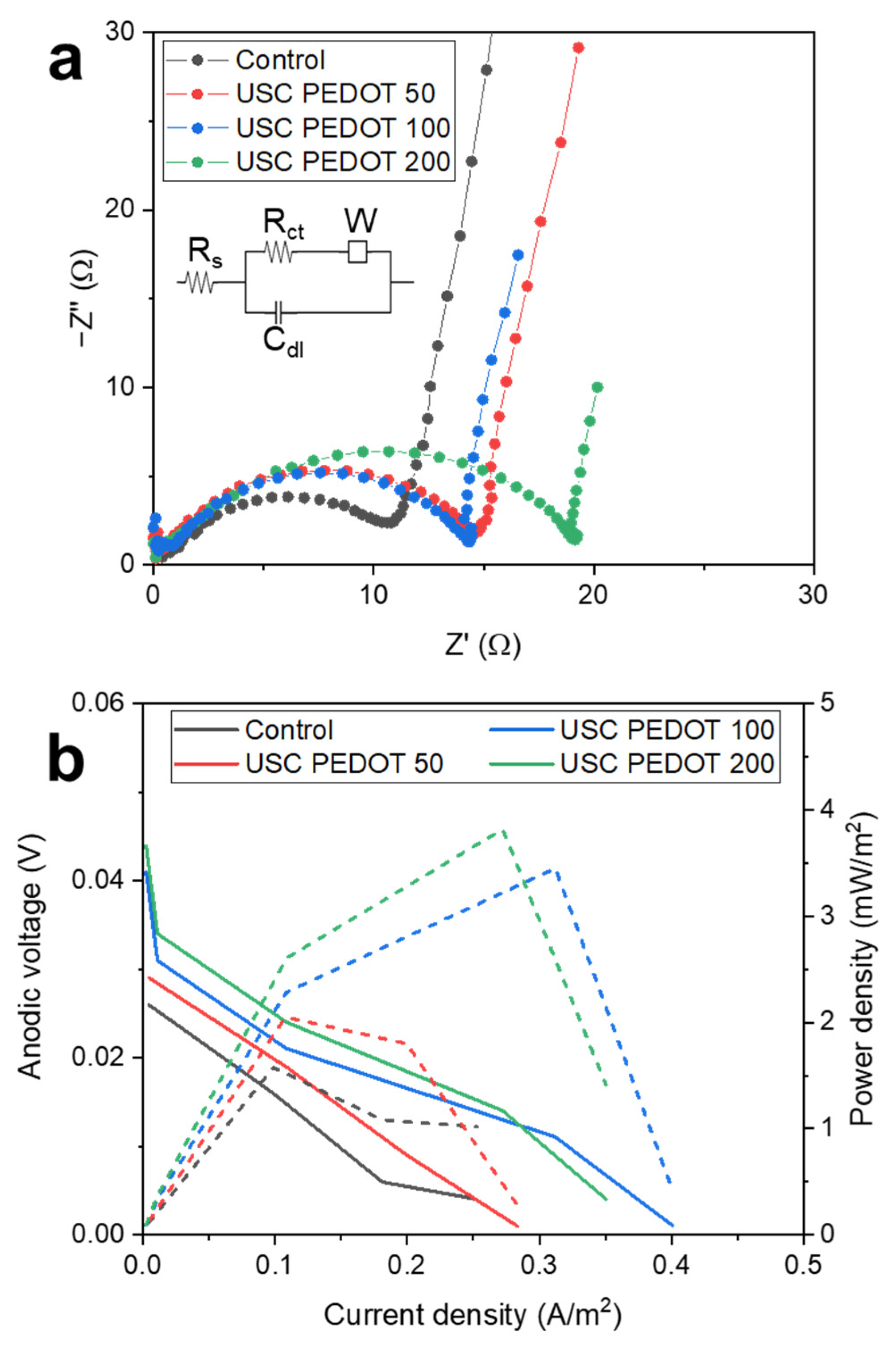
Figure 8a reports Nyquist plots obtained for all SCMFCs, which featured USC PEDOT 50, USC PEDOT 100 and USC PEDOT 200 as anodes electrodes, to be compared with the bare carbon paper control. From spectra acquired with a three-electrodes configuration, we focused our attention on the charge transfer resistance (R
ct) element, which is associated to the electrode−biofilm−electrolyte interface. Values obtained from fitting, averaged for each triplet, are reported in
Table 2.
It is possible to observe how all Rct values are compatible among all MFCs triplets, with the sole exception of the USC PEDOT 200 triplet, which presented a slightly increased Rct value, equal to (19 ± 2) Ω. This higher value might indicate a thicker biofilm formation on the anode electrode, thus also leading to confirm how the improved nanostructured layer uniformity, reached when 200 µg/cm2 of PEDOT were deposited, did not play an active role to define a significant enhancement of overall MFCs’ performance, unlike USC PEDOT 100, which induced a noticeable improvement of power output and energy recovery values respect to the ones reached with only carbon paper.
From LSV characterizations (
Figure 8b), we were able to confirm the trend observed in previous characterizations. Indeed, the performance of carbon paper electrodes were significantly increased by USC PEDOT 100 and USC PEDOT 200 electrodes. Nonetheless, no significant improvement can be observed when increasing PEDOT:PSS amount above 100 µg/cm
2.
Considering open circuit potentials, measured values were 26 mV (Control), 29 mV (USC PEDOT 50), 41 mV (USC PEDOT 100) and 44 mV (USC PEDOT 200).
In terms of short circuit current, USC PEDOT 100 performed best at 401 mA/m2, while USC PEDOT 200 provided 350 mA/m2. Instead, the current for USC PEDOT 50 was 283 mA/m2, slightly higher than control cell providing 252 mA/m2.
4. Conclusions
In this work we demonstrated the suitability of Ultrasonic Spray Coating as a promising technique to obtain nanostructured layer for optimizing carbon electrodes suitable for application as anodes in bio-electrochemical devices. In particular, we confirmed the possibility to apply USC to water-based inks containing the intrinsically conductive polymer PEDOT:PSS. All the achieved results allowed concluding that the nanostructured of PEDOT:PSS layer obtained on the electrodes’ surface was able to optimally cover the complex structure of carbon-based electrodes, leading thus to combine the continuous electrical conductivity of PEDOT:PSS to the porosity of standard carbon-based materials. EDX characterizations and Raman spectroscopy confirmed PEDOT:PSS spatial uniform distribution onto the electrodes carbon backbone. This feature resulted to be pivotal in optimizing anodic surfaces to host and sustain electroactive biofilms. We were also able to demonstrate the pivotal role of PEDOT:PSS in increasing the electrochemical active surface area of the electrode up to two-fold the value reached by bare carbon paper. Finally, experiments performed employing the newly fabricated electrodes as anodes in SCMFC devices demonstrated the performance improvements provided by USC optimized anodes, with clear evidence that the best performance was achieved when USC PEDOT 100 electrodes were used as anodes in SCMFCs, without the necessity to further increase the amount of PEDOT distributed onto surface area of carbon papers. All the results obtained clearly and unequivocally highlight the benefits obtained when USC PEDOT 100 is used as an anode electrode in BES, confirming that beneficial effect from PEDOT:PSS by USC are associated to concentration of the conductive polymer is line to what proposed in the literature with other deposition methods.
Application of USC as a methodology to improve performances of anodes in Microbial Fuel Cells has been validated, resulting in a versatile technology for fabrication of nano-coatings that can be easily scaled up for deposition on large areas with optimal uniformity and conformity.
Author Contributions
Conceptualization, all authors; methodology, G.S., G.M., M.Q; validation, G.M., M.Q; formal analysis, G.S.; investigation, G.S.; resources, C.F.P., M.Q.; data curation, G.S., G.M., S.B.; writing—original draft preparation, G.S.; writing—review and editing, all authors; supervision, G.M., S.B., M.Q.; project administration, C.F.P., S.B., M.Q.; funding acquisition, C.F.P., S.B., M.Q. All authors have read and agreed to the published version of the manuscript.
Funding
This publication is part of the project NODES- which has received funding from the MUR – M4C2 1.5 of PNRR funded by the European Union – Next Generation EU (Grant agreement no. ECS00000036).
Conflicts of Interest
The authors declare no conflict of interest.
References
- Santoro, C.; Arbizzani, C.; Erable, B.; Ieropoulos, I. Microbial Fuel Cells: From Fundamentals to Applications. A Review. J. Power Sources 2017, 356, 225–244. [Google Scholar] [CrossRef]
- Slate, A.J.; Whitehead, K.A.; Brownson, D.A.C.; Banks, C.E. Microbial Fuel Cells: An Overview of Current Technology. Renew. Sustain. Energy Rev. 2019, 101, 60–81. [Google Scholar] [CrossRef]
- Logan, B.E. Microbial Fuel Cells; 2008;
- Zhang, T.; Chen, Y.; Li, Y.; Chen, P.; Ma, H.; Han, P.; Wang, C.; Liu, W.; Wang, Y.; Qing, R.; et al. Investigating the Effect of Anode Materials on the Performance and Microbial Community in an Integrated Chamber-Free Microbial Fuel Cell. Fuel 2024, 357, 129648. [Google Scholar] [CrossRef]
- Vázquez, I.; Kerzenmacher, S.; Santiago, Ó. Stainless Steel Wool as Novel Bioanode for Microbial Electrolysis Cells: A Systematic Study of Materials. Front. Energy Res. 2023, 11, 1119090. [Google Scholar] [CrossRef]
- Ul, Z.; Sánchez-Peña, P.; Baeza, M.; Sulonen, M.; Gabriel, D.; Baeza, J.A.; Guisasola, A. Systematic Screening of Carbon-based Anode Materials for Bioelectrochemical Systems. J. Chem. Technol. Biotechnol. 2023, jctb.7357. [Google Scholar] [CrossRef]
- Kong, S.; Zhao, J.; Li, F.; Chen, T.; Wang, Z. Advances in Anode Materials for Microbial Fuel Cells. Energy Technol. 2022, 2200824. [Google Scholar] [CrossRef]
- Apostolopoulos, I.; Bampos, G.; Soto Beobide, A.; Dailianis, S.; Voyiatzis, G.; Bebelis, S.; Lyberatos, G.; Antonopoulou, G. The Effect of Anode Material on the Performance of a Hydrogen Producing Microbial Electrolysis Cell, Operating with Synthetic and Real Wastewaters. Energies 2021, 14, 8375. [Google Scholar] [CrossRef]
- Sanchez, J.-L.; Pinto, D.; Laberty-Robert, C. Electrospun Carbon Fibers for Microbial Fuel Cells: A Novel Bioanode Design Applied to Wastewater Treatment. Electrochimica Acta 2021, 373, 137864. [Google Scholar] [CrossRef]
- Cai, T.; Meng, L.; Chen, G.; Xi, Y.; Jiang, N.; Song, J.; Zheng, S.; Liu, Y.; Zhen, G.; Huang, M. Application of Advanced Anodes in Microbial Fuel Cells for Power Generation: A Review. Chemosphere 2020, 248, 125985. [Google Scholar] [CrossRef] [PubMed]
- Salar-García, M.J.; Ieropoulos, I. Optimisation of the Internal Structure of Ceramic Membranes for Electricity Production in Urine-Fed Microbial Fuel Cells. J. Power Sources 2020, 451, 227741. [Google Scholar] [CrossRef]
- Lim, S.S.; Yu, E.H.; Daud, W.R.W.; Kim, B.H.; Scott, K. Bioanode as a Limiting Factor to Biocathode Performance in Microbial Electrolysis Cells. Bioresour. Technol. 2017, 238, 313–324. [Google Scholar] [CrossRef]
- Liu, X.; Wu, W.; Gu, Z. Poly (3,4-Ethylenedioxythiophene) Promotes Direct Electron Transfer at the Interface between Shewanella Loihica and the Anode in a Microbial Fuel Cell. J. Power Sources 2015, 277, 110–115. [Google Scholar] [CrossRef]
- Park, S.-G.; Rhee, C.; Jadhav, D.A.; Eisa, T.; Al-Mayyahi, R.B.; Shin, S.G.; Abdelkareem, M.A.; Chae, K.-J. Tailoring a Highly Conductive and Super-Hydrophilic Electrode for Biocatalytic Performance of Microbial Electrolysis Cells. Sci. Total Environ. 2023, 856, 159105. [Google Scholar] [CrossRef] [PubMed]
- Massaglia, G.; Frascella, F.; Chiadò, A.; Sacco, A.; Marasso, S.L.; Cocuzza, M.; Pirri, C.F.; Quaglio, M. Electrospun Nanofibers: From Food to Energy by Engineered Electrodes in Microbial Fuel Cells. Nanomaterials 2020, 10, 523. [Google Scholar] [CrossRef] [PubMed]
- Massaglia, G.; Margaria, V.; Fiorentin, M.R.; Pasha, K.; Sacco, A.; Castellino, M.; Chiodoni, A.; Bianco, S.; Pirri, F.C.; Quaglio, M. Nonwoven Mats of N-Doped Carbon Nanofibers as High-Performing Anodes in Microbial Fuel Cells. Mater. Today Energy 2020, 16, 100385. [Google Scholar] [CrossRef]
- Kang, Y.L.; Pichiah, S.; Ibrahim, S. Facile Reconstruction of Microbial Fuel Cell (MFC) Anode with Enhanced Exoelectrogens Selection for Intensified Electricity Generation. Int. J. Hydrog. Energy 2017, 42, 1661–1671. [Google Scholar] [CrossRef]
- Guzman, J.J.L.; Pehlivaner Kara, M.O.; Frey, M.W.; Angenent, L.T. Performance of Electro-Spun Carbon Nanofiber Electrodes with Conductive Poly(3,4-Ethylenedioxythiophene) Coatings in Bioelectrochemical Systems. J. Power Sources 2017, 356, 331–337. [Google Scholar] [CrossRef]
- Kang, Y.L.; Ibrahim, S.; Pichiah, S. Synergetic Effect of Conductive Polymer Poly(3,4-Ethylenedioxythiophene) with Different Structural Configuration of Anode for Microbial Fuel Cell Application. Bioresour. Technol. 2015, 189, 364–369. [Google Scholar] [CrossRef]
- Sun, K.; Zhang, S.; Li, P.; Xia, Y.; Zhang, X.; Du, D.; Isikgor, F.H.; Ouyang, J. Review on Application of PEDOTs and PEDOT:PSS in Energy Conversion and Storage Devices. J. Mater. Sci. Mater. Electron. 2015, 26, 4438–4462. [Google Scholar] [CrossRef]
- Rahimzadeh, Z.; Naghib, S.M.; Zare, Y.; Rhee, K.Y. An Overview on the Synthesis and Recent Applications of Conducting Poly(3,4-Ethylenedioxythiophene) (PEDOT) in Industry and Biomedicine. J. Mater. Sci. 2020, 55, 7575–7611. [Google Scholar] [CrossRef]
- Gao, N.; Yu, J.; Tian, Q.; Shi, J.; Zhang, M.; Chen, S.; Zang, L. Application of PEDOT:PSS and Its Composites in Electrochemical and Electronic Chemosensors. Chemosensors 2021, 9, 79. [Google Scholar] [CrossRef]
- Bhat, M.A.; Rather, R.A.; Shalla, A.H. PEDOT and PEDOT:PSS Conducting Polymeric Hydrogels: A Report on Their Emerging Applications. Synth. Met. 2021, 273, 116709. [Google Scholar] [CrossRef]
- Ma, Q.; Pu, K.-B.; Cai, W.-F.; Wang, Y.-H.; Chen, Q.-Y.; Li, F.-J. Characteristics of Poly(3,4-Ethylenedioxythiophene) Modified Stainless Steel as Anode in Air-Cathode Microbial Fuel Cells. Ind. Eng. Chem. Res. 2018, 57, 6633–6638. [Google Scholar] [CrossRef]
- Mishra, P.; Malla, M.A.; Gupta, S.K.; Mishra, P.; Malla, M.A.; Gupta, S.K. Poly(3,4-ethylenedioxythiophene)-Modified Graphite Felt and Carbon Cloth Anodes for Use in Microbial Fuel Cells. ChemistrySelect 2022, 7, e202103920. [Google Scholar] [CrossRef]
- Engle, R. Maximizing the Use of Platinum Catalyst by Ultrasonic Spray Application. J. Fuel Cell Sci. Technol. 2012, 9, 014501. [Google Scholar] [CrossRef]
- Ely, F.; Matsumoto, A.; Zoetebier, B.; Peressinotto, V.S.; Hirata, M.K.; de Sousa, D.A.; Maciel, R. Handheld and Automated Ultrasonic Spray Deposition of Conductive PEDOT:PSS Films and Their Application in AC EL Devices. Org. Electron. 2014, 15, 1062–1070. [Google Scholar] [CrossRef]
- Grandi, M.; Rohde, S.; Liu, D.J.; Gollas, B.; Hacker, V. Recent Advancements in High Performance Polymer Electrolyte Fuel Cell Electrode Fabrication – Novel Materials and Manufacturing Processes. J. Power Sources 2023, 562, 232734. [Google Scholar] [CrossRef]
- Turtayeva, Z.; Xu, F.; Dillet, J.; Mozet, K.; Peignier, R.; Celzard, A.; Maranzana, G. Manufacturing Catalyst-Coated Membranes by Ultrasonic Spray Deposition for PEMFC: Identification of Key Parameters and Their Impact on PEMFC Performance. Int. J. Hydrog. Energy 2022, 47, 16165–16178. [Google Scholar] [CrossRef]
- Erkan, S.; Eroglu, I. Ultrasonic Spray Coating Technique for High-Performance PEM Fuel Cell Electrode Manufacturing. In Progress in Clean Energy, Volume 2; Dincer, I., Colpan, C.O., Kizilkan, O., Ezan, M.A., Eds.; Springer International Publishing: Cham, 2015; pp. 481–492. ISBN 978-3-319-17030-5. [Google Scholar]
- Griffin, J.; Ryan, A.J.; Lidzey, D.G. Solution Modification of PEDOT:PSS Inks for Ultrasonic Spray Coating. Org. Electron. 2017, 41, 245–250. [Google Scholar] [CrossRef]
- Lonakar, G.S.; Mahajan, M.S.; Ghosh, S.S.; Sali, J.V. Modeling Thin Film Formation by Ultrasonic Spray Method: A Case of PEDOT:PSS Thin Films. Org. Electron. 2012, 13, 2575–2581. [Google Scholar] [CrossRef]
- Spisni, G.; Massaglia, G.; Pirri, C.F.; Bianco, S.; Quaglio, M. Nanostructured Layer Based on Intrinsically Conductive Polymers for Optimising Carbon Electrodes’ Surface: Electrospray and Ultrasonic Spray Coating. In Proceedings of the IOCN 2023; MDPI, May 5 2023; p. 53.
- Quaglio, M.; Massaglia, G.; Vasile, N.; Margaria, V.; Chiodoni, A.; Salvador, G.P.; Marasso, S.L.; Cocuzza, M.; Saracco, G.; Pirri, F.C. A Fluid Dynamics Perspective on Material Selection in Microbial Fuel Cell-Based Biosensors. Int. J. Hydrog. Energy 2019, 44, 4533–4542. [Google Scholar] [CrossRef]
- Cheng, S.; Liu, H.; Logan, B.E. Power Densities Using Different Cathode Catalysts (Pt and CoTMPP) and Polymer Binders (Nafion and PTFE) in Single Chamber Microbial Fuel Cells. Environ. Sci. Technol. 2006, 40, 364–369. [Google Scholar] [CrossRef]
- Wang, H.; Long, X.; Sun, Y.; Wang, D.; Wang, Z.; Meng, H.; Jiang, C.; Dong, W.; Lu, N. Electrochemical Impedance Spectroscopy Applied to Microbial Fuel Cells: A Review. Front. Microbiol. 2022, 13, 973501. [Google Scholar] [CrossRef] [PubMed]
- Agostino, V.; Ahmed, D.; Sacco, A.; Margaria, V.; Armato, C.; Quaglio, M. Electrochemical Analysis of Microbial Fuel Cells Based on Enriched Biofilm Communities from Freshwater Sediment. Electrochimica Acta 2017, 237, 133–143. [Google Scholar] [CrossRef]
- Dominguez-Benetton, X.; Sevda, S.; Vanbroekhoven, K.; Pant, D. The Accurate Use of Impedance Analysis for the Study of Microbial Electrochemical Systems. Chem. Soc. Rev. 2012, 41, 7228. [Google Scholar] [CrossRef]
- Massaglia, G.; Sacco, A.; Chiodoni, A.; Pirri, C.F.; Quaglio, M. Living Bacteria Directly Embedded into Electrospun Nanofibers: Design of New Anode for Bio-Electrochemical Systems. Nanomaterials 2021, 11, 3088. [Google Scholar] [CrossRef] [PubMed]
- Li, J.; Li, H.; Zheng, J.; Zhang, L.; Fu, Q.; Zhu, X.; Liao, Q. Response of Anodic Biofilm and the Performance of Microbial Fuel Cells to Different Discharging Current Densities. Bioresour. Technol. 2017, 233, 1–6. [Google Scholar] [CrossRef]
- Kim, B.; Chang, I.S.; Dinsdale, R.M.; Guwy, A.J. Accurate Measurement of Internal Resistance in Microbial Fuel Cells by Improved Scanning Electrochemical Impedance Spectroscopy. Electrochimica Acta 2021, 366, 137388. [Google Scholar] [CrossRef]
|
Disclaimer/Publisher’s Note: The statements, opinions and data contained in all publications are solely those of the individual author(s) and contributor(s) and not of MDPI and/or the editor(s). MDPI and/or the editor(s) disclaim responsibility for any injury to people or property resulting from any ideas, methods, instructions or products referred to in the content. |
© 2023 by the authors. Licensee MDPI, Basel, Switzerland. This article is an open access article distributed under the terms and conditions of the Creative Commons Attribution (CC BY) license (http://creativecommons.org/licenses/by/4.0/).
