Preprint
Article

Optimal Design and Fish-Passing Performance Analysis of Fish-Friendly Axial Flow Pump

This version is not peer-reviewed.

Submitted:

03 October 2023

Posted:

03 October 2023

You are already at the latest version

A peer-reviewed article of this preprint also exists.

Abstract
In the process of construction and operation of the pumping station, a large number of axial flow pumps pose a threat to the survival of fish in the natural environment. Through experiments, the survival conditions of many kinds of fish in extreme positive and negative pressure environment are explored, and -40 kPa is established as the low pressure damage threshold, which is used as a reference to analyze the probability of fish damage caused by pumps. The immersion boundary-lattice Boltzmann numerical method (LES-IB-LBM) based on large eddy simulation is used to optimize the parameters of the prototype runner of axial flow pump. A new type of runner with leading edge thickness of 11.4mm and blade cutting angle of 18 ° is optimized. This kind of runner has both hydraulic performance and fish-passing ability. The runner of the fish-friendly axial flow pump effectively guides the fish into the low risk area and reduces the risk of friction, shear and impact damage to the fish. the total impact mortality ratio of the runner of the axial flow pump before and after optimization is close to 7:1. The pressure damage analysis shows that the lowest negative pressure of the fish is -59.2 kPa, which is higher than -64.5 kPa of the prototype pump, and the highest positive pressure of the body surface is 11.8 kPa, which is lower than the 43.8 kPa of the prototype pump. Shear damage analysis shows that the fish will not be damaged by shear in the prototype pump and fish-friendly pump.
Keywords: 
Subject: 
Engineering  -   Mechanical Engineering

1. Introduction

Because of the characteristics of large transmission flow and low transport head, axial flow pump is equipped in water network and water system on a large scale, undertaking important missions such as inter-basin water transfer, flood control and drainage, drought resistance and disaster reduction [1]. The dense pumping stations have a particularly great impact on the reproduction and spawning of migratory fish, and the extinction of fish stocks caused by the failure to lay eggs will significantly affect the entire ecosystem [2]. According to the fish ladder that has been put into use in all kinds of dam water control projects, the actual operation effect is not Effective [3]. In addition, many pumping stations responsible for water transfer, drainage and irrigation are located in areas where a large number of fish gather. However, its own operating conditions are difficult to support the construction of fish ladder, so the key to solve the problem lies in how to reduce the casualty rate of fish passing through hydraulic machinery.
The probability of fish injury is closely related to the shape of key flow channels of hydraulic machinery [4,5]. Fish may be subjected to mechanical, pressure, shear, and cavitation erosion damage [6,7]. Shao et al. [8,9] found that negative pressure caused more damage to fish than positive pressure. Cada[10] found that the pressure threshold of swim bladder fish was 0.3 times atmospheric pressure, and that of swim bladder closed fish was 0.6 times atmospheric pressure. When the pressure in the pressure channel is lower than -50 kPa, about half an atmosphere, fish are vulnerable to damage [5]. When the internal pressure drop rate of the turbine is greater than 3.5MPa /s, the fish body will be damaged by pressure gradient [11]. High shear strain rates have been found near the blades, guide blades, runner, and draft pipes of large axial flow propeller turbines [12]. Neitzel et al. [13,14] pointed out that the safe threshold of shear strain rate for fish damaged by fluid shear force and turbulence is 500 s-1.
The design theory of the axial flow pump is determined by its three-dimensional unsteady flow characteristics and high specific speed characteristics. The binary design theory is usually used in the design, mainly the plane in-line cascade design theory [15]. Among the traditional design methods of axial flow pump runner blades, conformal transformation, singularity distribution, and lift methods are the most widely used. In the era when computational fluid dynamics is widely used, numerical calculation can achieve more detailed and in-depth information extraction in the exploration of the internal flow law of hydraulic machinery [16], which reduces the research threshold for axial flow pumps and other hydraulic machinery.
In the 1990s, the fish-friendly hydraulic turbine was first designed in the AHTS project in the United States. The Alden [17,18] team designed a spiral centrifugal single-blade runner to reduce the pressure gradient and velocity gradient on the runner blade. The Voith [19,20] team put forward a new design concept that can reduce the damage rate of mechanical fish, including reducing the gap in the flow channel, reasonably arranging the position of fixed guide vane and movable guide vane, and so on. ALSTOM also designed a runner with minimum clearance from the same point of view as the Voith team. They minimize the gap between the blade and the hub and between the runner and the runner chamber, and effectively reduce the serious damage that fish may suffer when they get stuck in the gap. In addition, they also reduce the cavitation and shear phenomena near the runner to some extent [21,22]. David [23] and Li [24] studied a kind of upward-flow hydraulic turbine, which removed the draft tube structure. This significantly increases the amount of dissolved air in the current, improves the drastic change of pressure, and reduces the damage caused by the fish passing through the machine. The team of Zhang of Jiangsu University in China and Bosman Water management Co., Ltd. in the Netherlands used the blade impact model [25] to predict the damage of fish passing through the pump. It was found that the impact probability and mortality of fish passing through the runner passage of the axial flow pump were affected by the number of blades and the bending and sweeping of the leading edge of the blades, respectively. They also designed axial flow pump runners with low impact and no impact damage. Pan et al. [26] combined the Lagrangian tracking method with computational fluid dynamics to discuss the motion behavior and damage mechanism of fish passing through an axial flow pump.
At present, the research on fish-friendly hydraulic machinery is still in the early stage of exploration, lack more reliable analysis methods and research methods. In this paper, taking the axial flow pump as the research object, the fluid numerical calculation method suitable for simulating the movement of organisms is used to study the fish damage in the axial flow pump, combined with the design criteria and relevant evaluation indexes to adapt to the hydraulic mechanical characteristics of the fish. furthermore, the geometric structure optimization design of the fish-friendly axial flow pump is completed, which helps the development of water security and water ecological construction to higher quality in our country.

2. Experiment

2.1. Experimental device and experimental fish

Figure 1 is a three-dimensional model of the pressure damage analysis test device for fish.
The whole set of test device consists of three steel cylindrical pressure tanks. The main test equipment is a visual steel tank (T2) located in the middle, a high-pressure steel tank (T1) connected on one side of the tank, and a vacuum steel tank (T3) on the other side. The high-pressure steel tank and vacuum steel tank are used to quickly control the internal pressure of the system, so the two steel tanks are externally connected with high-power air compressor and a high-power vacuum pump respectively. The tank size is customized according to the size of the test site, and the motor power meets the maximum test requirements. The visual steel tank is designed as an up-lift steel tank, which holds about 1 ton of water for the test fish in the experiment. A toughened glass window is arranged at the height of 1.5m in front of the tank, and the pressure resistance of the glass is above the test pressure range.
In this paper, three common freshwater fish species, cultured crucian carp, wild crucian carp, and yellow catfish, were selected in the pressure damage experiment. The average body length was 120mm.

2.2. Experimental Scheme

The laboratory temperature regulator was turned on the day before the experiment, the fresh air device was turned on, and the indoor air temperature was kept at 18 ℃. Turn on the oxygen supply to ensure that the experiment water is clean and clear without impurities. When the experimental water is put into the culture tank, the pH value and water temperature should be measured to ensure that the pH is 7±5% and the water temperature is in the range of 15 ℃±1 ℃. The experimental fish were reared in the laboratory environment for more than 24 hours, and the fish with poor vital signs were removed before the start of the experiment.
In the course of the experiment, the positive pressure retention values were 340 kPa and 680 kPa, and the negative pressure retention values were -20 kPa, -40 kPa , and -80 kPa, respectively. After the visible steel pipe reaches the specified pressure, the fish stays in T2 for three minutes to observe the fish’s reaction. At the end of the experiment, restore the pressure in the experiment tank to atmospheric pressure, take out the experiment fish, put them in a designated flume for culture, and record the fish damage. The related process and results of the experiment are shown in Table 1 and Table 2.

2.3. Experimental Results and Analysis

In this experiment, a set of devices suitable for internal pressure simulation of hydraulic machinery is constructed. The device mainly includes pressure tank, air compressor, vacuum pump, pressure monitoring device, a number of valves, and connecting pipes. It is found that the two kinds of crucian carp show the movement characteristics or trend of resisting the change of pressure when the external pressure changes. Qualitatively, wild crucian carp is more sensitive and flexible than cultured fish. Different fish species have different abilities to withstand positive and negative pressure. Whether positive pressure or negative pressure, the survival ability of wild crucian carp is stronger than cultured crucian carp. Excluding the effect of the experimental culture environment on fish bodies in the control group, and based on the survival ratio of 80%, the negative pressure survival threshold of wild crucian carp and yellow catfish should be determined as -40 kPa. If the stay time is less than 2 min in a pressure environment higher than -40 kPa, both kinds of fish can ensure healthy survival. The survival rate of cultured crucian carp under negative pressure was significantly lower than that of other fish. Therefore, this paper establishes -40 kPa as the low-pressure damage threshold, which is used as a reference to analyze the probability of fish damage caused by hydraulic turbine.
Through the anatomy of two kinds of crucian carp and yellow catfish, it was found that the body damage of positive and negative pressure was mainly concentrated in swim bladder, eyeball, fin junction, skin, and so on. The injured or dead fish had congestion on the surface of the eyeball, body surface, and fin junction, and the rupture of the swim bladder of most fish could be observed under strong negative pressure. We can find that the rupture and shrinkage of the swim bladder is the direct cause of fish death on the spot, and other complications caused by positive and negative pressure are the key factors to determine the final mortality of experimental fish.

3. Numerical simulation method and main parameters of the model

3.1. IB-LBM method

In this paper, the submerged boundary-lattice Boltzmann method (IB-LBM) is used to study the trajectory and damage of fish passing through an axial flow pump. The Immersed Boundary Method (IBM) is also essentially a boundary-handling format. The basic idea of IBM is to approximate the boundary of an object by a set of marked points close to the mesh. These marked points affect the fluid only through the force field, and an interpolation template is introduced to transfer information between the mesh points and the marked points. This makes the implementation of complex boundaries relatively simple. The combination of IBM and LBM, proposed by Feng and Michaelides, is called The Immersed Boundary-Lattic Boltzmann Method (IB-LBM).
The lattice Boltzmann method is a particle-based solver, and the calculation depends on a set of automatically generated octree structured lattices [27,28], which avoids the error-prone of unstructured mesh reconstruction. The LBM scheme allows the use of large eddy simulation turbulence models at low computational costs and efficiently solves numerical problems through Boltzmann transport equations. Scholars such as Cheng and Li [29,30] of Wuhan University have obtained the transient flow data of a three-dimensional tubular turbine by IB-LBM. The calculation shows that when simulating the load rejection and increasing load conditions of the cross-flow turbine, the velocity change, pressure change characteristics and the increase and decrease law of axial force obtained by IB-LBM accord with the conventional conditions, and can achieve better transient flow simulation results. Li [31,32] of Xi’an University of Technology calculated the motion of thin-scale salmon in a tubular turbine by using the submerged boundary-lattice Boltzmann coupling method and analyzed the pressure and pressure gradient damage suffered by the fish passing through the inner passage of the turbine. The results show that the IB-LBM method can simulate the spatial location and damage of fish in the hydraulic turbine.
By discretizing the Boltzmann equation in several dimensions such as velocity, physical space, and time, the basic form of the lattice Boltzmann equation can be obtained:
f i ( x + c i Δ t , t + Δ t ) = f i ( x , t ) + ω i ( x , t )
In the formula, the distribution function and equilibrium distribution function are finite discrete terms.
Because the original collision operator of the Boltzmann equation is extremely complex, the linearized BGK collision model proposed by Bhatnagar, Gross, and Krook based on the H theorem has been proved to be an effective collision operator to simulate Navier-Stokes behavior. Formula (2) is the mathematical expression of the discrete Bhatnagar-Gross-Krook (BGK) operator:
ω i ( f ) = f i f i e q τ Δ t
where τ is the relaxation time, which determines the rate at which particle swarm f i x , t relaxes to equilibrium state f i e q .
Boltzmann H theorem holds that the distribution function changes with time. The H (the function representing the change) of the system always decreases, and when H gradually decreases to the minimum and no longer changes, the whole system will enter the equilibrium state. This process is irreversible. As a result, the lattice BGK equation (Lattice BGK Equation, LBGK) with important application significance can be derived.
f i ( x + c i Δ t , t + Δ t ) f i ( x , t ) = Δ t τ ( f i ( x , t ) f i e q ( x , t ) )
Because the BGK operator in the LBGK equation contains a relaxation time that represents the relaxation rate of the equilibrium function, it is also called the single relaxation model. The collision and flow processes of solving the lattice Boltzmann model are based on the Cartesian mesh system of geometric objects. In order to better adapt to the object boundary to represent the computing domain, the Octree Algorithm (OA) is usually used as the basic algorithm to generate the 3D lattice model. The octree algorithm is a top-down algorithm with strong scalability and can dynamically generate lattice models for different uses according to the needs of users. The generation rules of the octree determine that once its structure is generated, the child lattice of any lattice in the tree can only be zero or eight, and there can be no other cases. So its logical structure is a tree structure that may have eight bifurcations in any lattice.

3.2. Model geometric structure and parameters

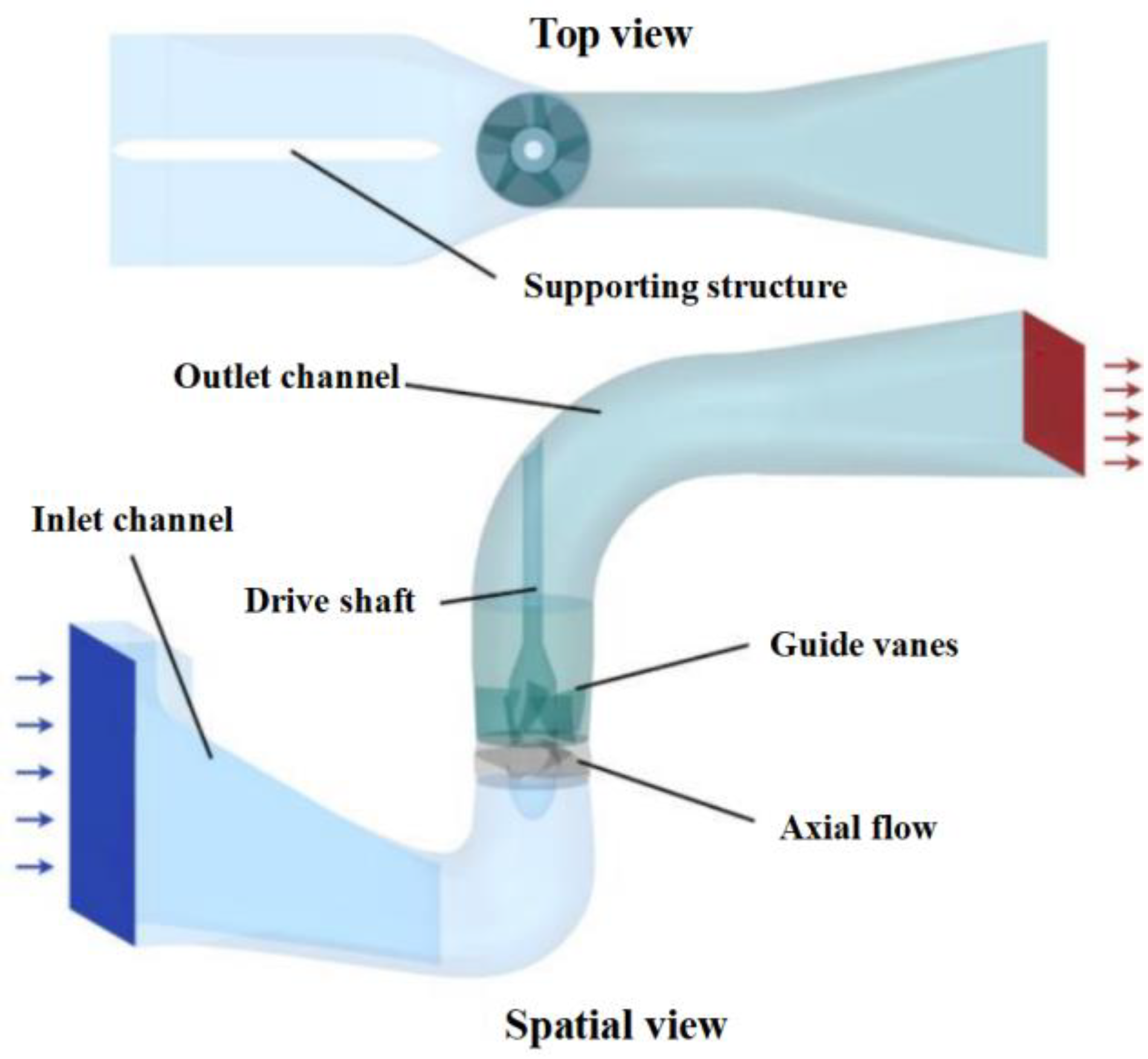
The model used in the calculation is a three-dimensional model of the full flow channel of the axial flow pump, including the inlet channel, the runner section, the diversion mechanism section, and the outlet channel. The main parameters for the design and operation of the axial flow pump are shown in Table 3.
The geometric structure and components of the axial flow pump are shown in Figure 3.
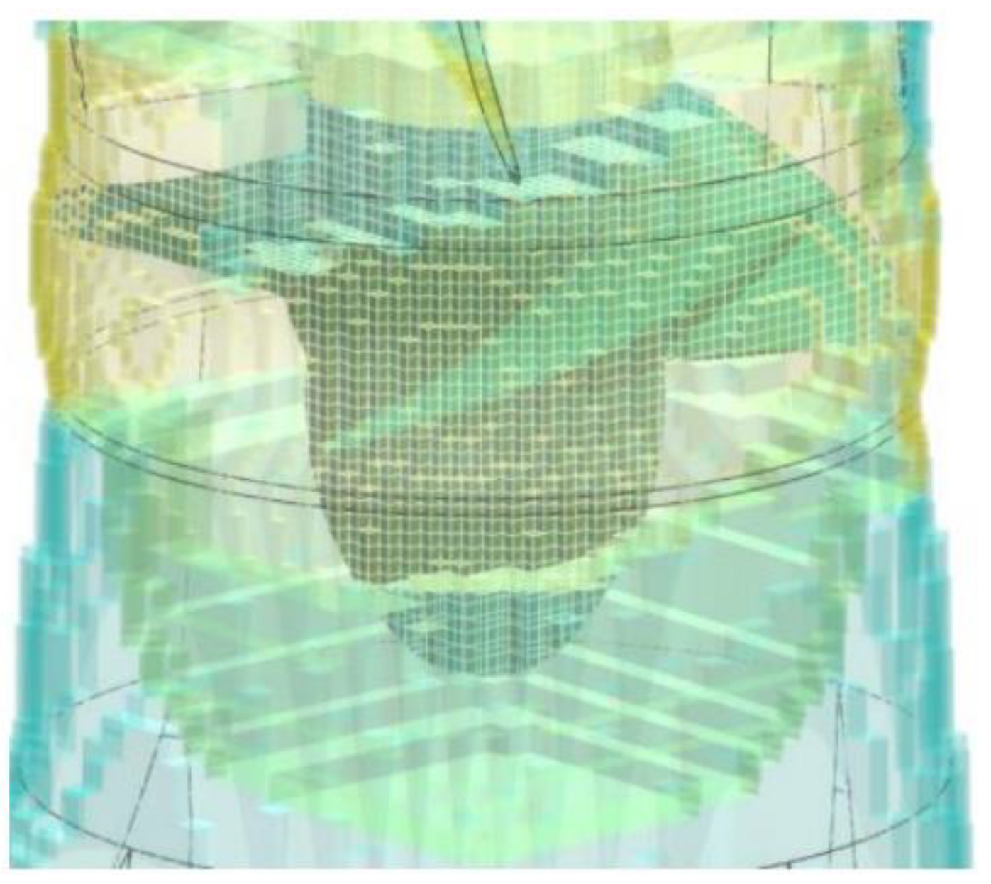
In this paper, for the three-dimensional calculation of the axial flow pump, the maximum discrete velocity number scheme of D3Q27 and the octree lattice structure are used to organize the lattice scale refinement scheme in different regions of the fluid domain. Specifically, the division of the lattice structure realizes the construction of the whole channel lattice model by setting the scale for each part of the original geometric structure or drawing the geometric inclusion structure to set the analytical scale and far-field scale for the corresponding region. Schemes of different mesh sizes are shown in Figure 4.
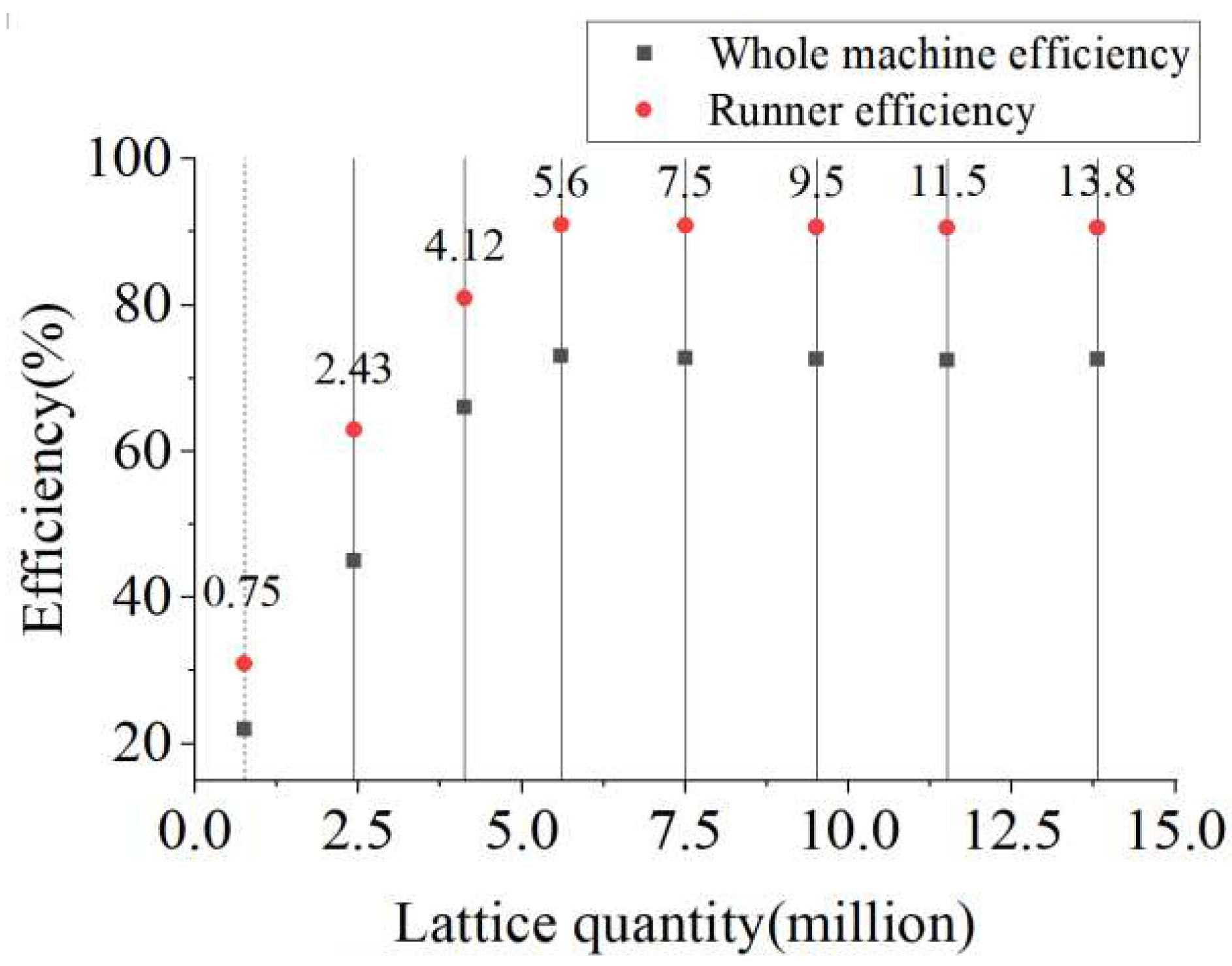
In this paper, the time step is calculated by the combination of the Coulomb number and local lattice scale, which is generated dynamically by the algorithm. The Coulomb number is a parameter that characterizes whether the calculation conforms to the CFL condition, usually between 0.2 and 1. In order to ensure the robustness of the calculation, the Coulomb number is 0.4. The unsteady calculation of the axial flow pump is carried out by using several schemes with different analytical scales, and the irrelevant verification curve in Figure 4 is obtained. Because different lattice scales are used in the runner region and other regions, the runner efficiency and the whole machine efficiency are selected as the evaluation index of lattice independence verification.
According to the results of irrelevance verification, the final selected mesh total scheme is not less than 560w at any time step, so as to meet the lattice independence requirements. Under this scheme, the global lattice scale is 0.025. In the local refinement lattice scale, the runner and wake are 0.00625-0.0125 adaptive refinement.
In the setting of boundary conditions, the inlet boundary is set as the mass flow inlet, and the numerical value is converted according to the designed flow rate. The pressure outlet boundary is set to atmospheric pressure. The wall boundary is added with the non-equilibrium strengthening wall function, in which the forced motion is added to the runner rotor structure. The motion characteristic parameters are converted into a function of time according to the rated speed. The coupling calculation of the immersion boundary method is used.

3.3. Evaluation method of blade impact probability

The high incidence area of the impact between fish and runner is the leading edge of runner blades. a large number of studies have shown that the impact probability of the blade leading edge is related to fish body length, orientation, swimming speed, and local fluid velocity. there is a certain relationship between the leading edge thickness of the runner blade and blade impact speed [33,34,35,36]. This complex relationship in axial flow pump can be expressed by the following formula:
P i m p a c t = t f i s h t b l a d e = min 1 , h f i s h L f i s h A b N b n r 60 Q r
where P i m p a c t is the probability of impact between the fish and the blade. t f i s h is the time for the fish to pass through the leading edge of the blade. t b l a d e is the time for the blade to walk through a leaf spacing. h f i s h is the correction coefficient of the effective length of the fish, which is related to the ratio of length to width of the fish, and is determined by the species of fish. Min function indicates that the calculated value should be less than 1.
The plate impact experiment of EPRI shows that the death probability of fish is directly related to the leading edge thickness and impact velocity of the blade.
C d e a d = p ln L f i s h d + q v s 4.8
where C d e a d is the fish impact death index, which characterizes the death probability of fish when they are hit by a plate. L f i s h d is the ratio of the length of the fish body to the thickness of the leading edge of the blade. v s is the impact velocity. p, q is the undetermined coefficient, respectively, and its value is affected by L f i s h d .
According to the formula, the impact velocity will directly increase the impact death probability, and the impact velocity below 4.8 m / s will not lead to fish death. When the threshold is exceeded, the death index increases exponentially with the increase of the impact velocity, and the magnification is the growth value of the impact velocity.

4. Optimal design and hydraulic performance analysis of fish-friendly axial flow pump

4.1. Optimal design of leading edge thickness of blade

Previous studies have shown that the part of the runner structure that causes cutting damage to fish is located at the leading edge of the blade. The leading edge structure of the blade is used to reduce the de-flow of the blade facing the incoming flow and reduce the hydraulic loss. From a fish-friendly point of view, increasing the thickness of the leading edge of the blade can avoid direct cutting when it hits the fish. However, the thickness of the leading edge of the blade is not the bigger the better. On the one hand, the greater thickness increases the possibility of de-flow and hydraulic loss, on the other hand, it also increases the probability of hitting fish. Therefore, the choice of the leading edge thickness of the blade needs to be analyzed.
Three runner schemes with different blade leading edge thicknesses are designed for the prototype axial flow pump, as shown in Figure 6.
We use the comparative analysis method to comprehensively analyze the operation characteristics and flow field characteristics of the axial flow pump under different blade leading edge thickness schemes and determine the better blade leading edge thickness.
According to Table 4, when the thickness of the leading edge of the blade increases, the head of the axial flow pump decreases. This shows that the mechanical energy obtained per unit mass of fluid is reduced. The inlet and outlet pressure of the blade decreased with the thickening of the leading edge of the blade, and the decrease was about 1.5kPa, and the decrease of the total pressure at the outlet was slightly larger than that at the inlet. On the one hand, it shows that the internal hydraulic loss of the runner increases with the thickening of the leading edge of the blade, on the other hand, the pressure difference between the front and rear of the runner shifts. Although increasing the thickness of the leading edge can reduce the negative pressure of the suction chamber and increase the suction head, the lower negative pressure will also increase the possibility of pressure damage to the upstream fish. The shaft power, runner efficiency, and machine efficiency all decrease to a certain extent with the increase of blade leading edge thickness.
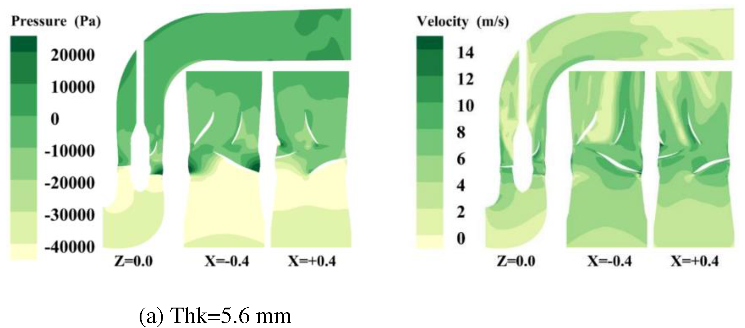
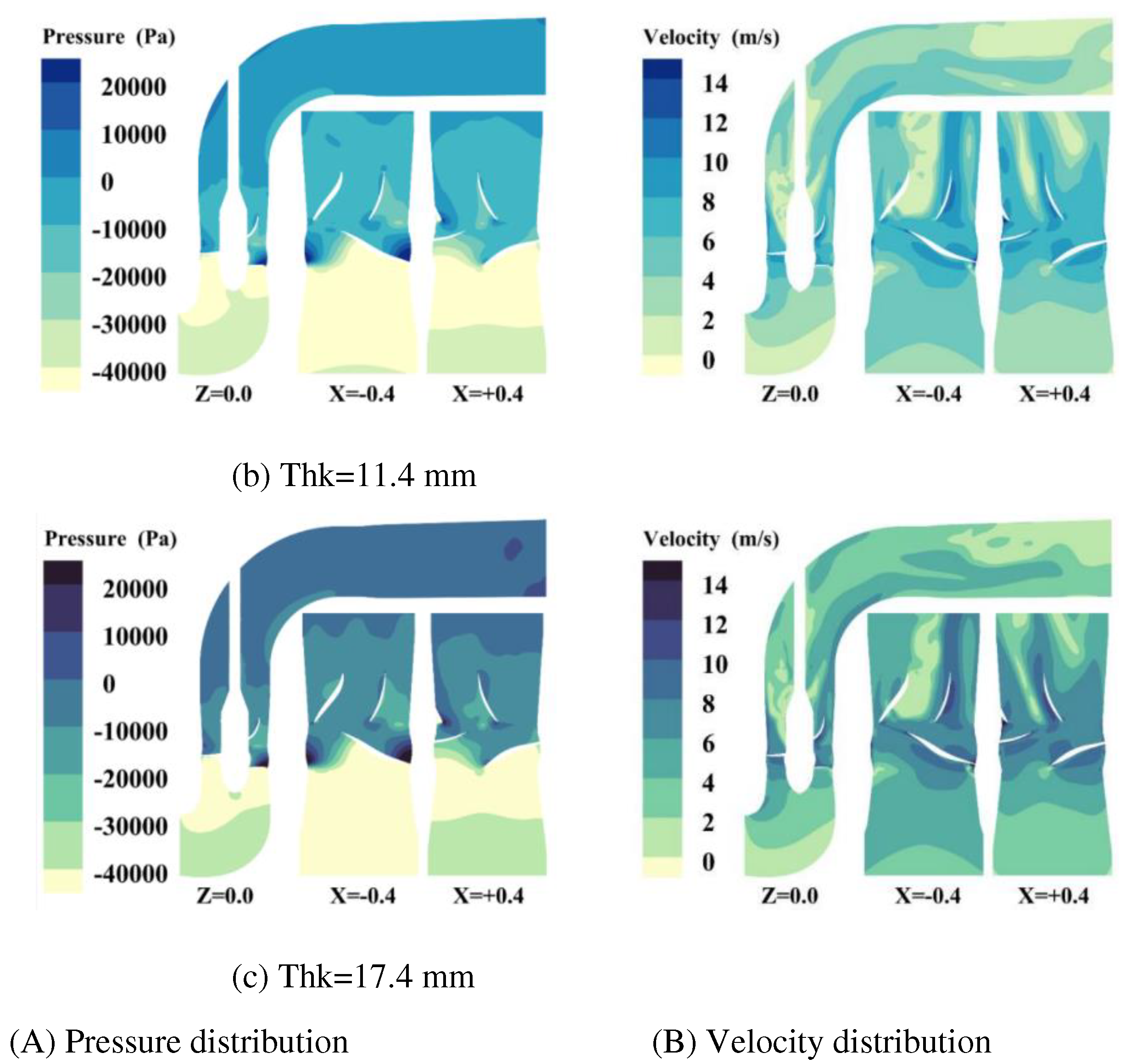
The cross-section pressure distribution of the axial flow pump under different blade leading edge thickness schemes is shown in Figure 7. As can be seen from the pressure distribution map, with the thickening of the leading edge of the blade, the area lower than -40 kPa gradually increases, and too large negative pressure area will cause irreversible negative pressure damage to the fish. From the velocity distribution map, it can be seen that in the case of 5.6mm, the velocity gradient at the leading edge of the blade and the guide vane region changes gently, and the smooth isovelocity lines can be obviously observed in both X-sections. The velocity distribution in the guide vane region of 11.4 mm and 17.4mm is more chaotic, which is caused by the increase in the leading edge thickness of the blade. In the velocity cloud image of 11.4mm, a smaller vortex core is derived from the guide vane region, and the vortex core basically disappears in the outlet bend section. The velocity cloud image of 17.4mm shows that a large-scale vortex is formed in the guide vane region, and the vortex still exists in the outlet channel.
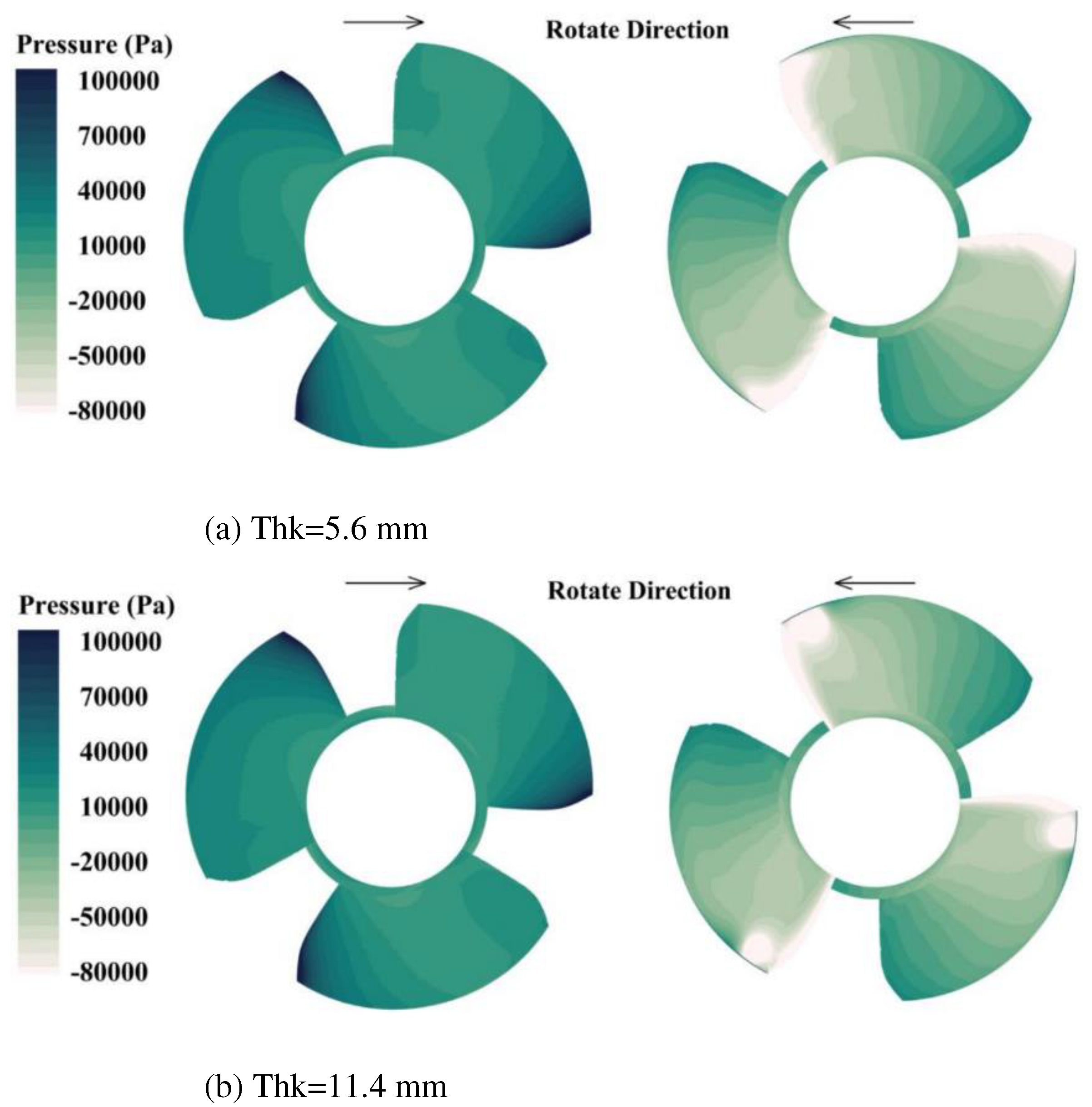
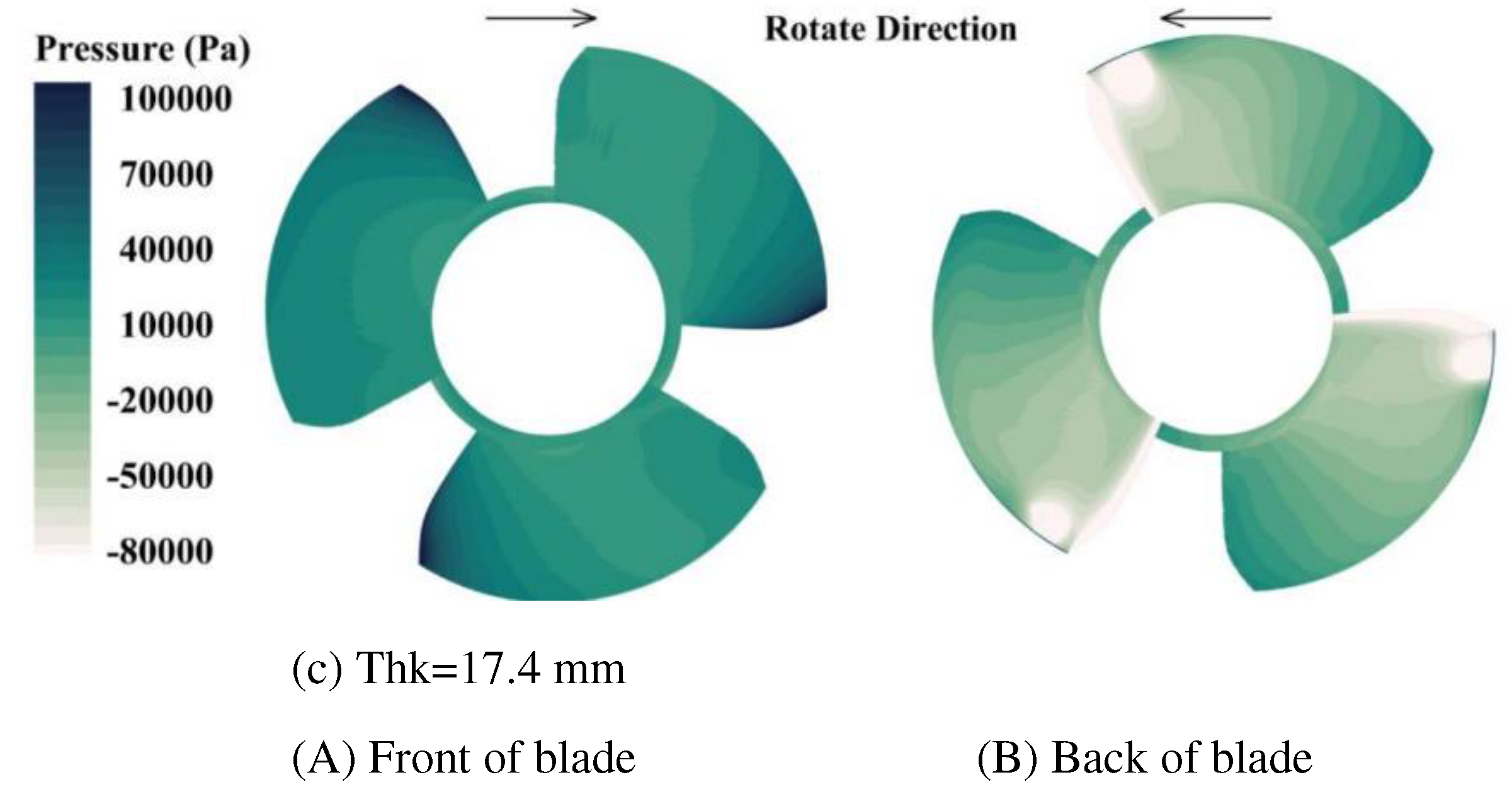
The surface pressure distribution of the runner blade shows that the effect of the increase of the leading edge thickness on the blade surface pressure is consistent with the values read in the external characteristic table. The specific results are as follows: for the blade working face, the positive pressure decreases slightly, while for the suction face, the proportion of the negative pressure less than -80 kPa is obviously larger. In addition, the increase in the thickness of the leading edge of the blade also makes the negative pressure limit region of the suction surface of the blade focus on a circular region.
The hydraulic performances of the axial flow pump with three-blade leading edge thickness schemes are comprehensively compared, and the fish-passing characteristics of the pressure performance are properly considered. Based on the analysis results of the visual data such as the operation efficiency of the axial flow pump, the negative pressure level of the pump suction chamber, the velocity and pressure distribution characteristics of the runner and guide vane, and the streamline of the outlet passage, it is obtained that it can reduce the damage probability of fish. The best compromise scheme with less performance sacrifice is the blade leading edge thickness 11.4mm scheme. The following will take this scheme as the benchmark, and continue to carry out the next link of the optimization design.

4.2. Optimal design of leading edge guiding characteristics of blade
When the runner rotates, the linear velocity of the leading edge of the blade is proportional to the radius. When the speed of the runner is constant, the position of the fish entering and leaving the runner is closer to the hub side, and the smaller the impact velocity is. Therefore, the effective way to reduce the impact speed of fish is to make the fish enter the flow channel from the inside of the runner as far as possible. For the runner, the cutting blade can make the entrance of the runner have a certain radial velocity, so that the position of the fish entering the runner is closer to the hub side, thus reducing the death rate in the event of impact.
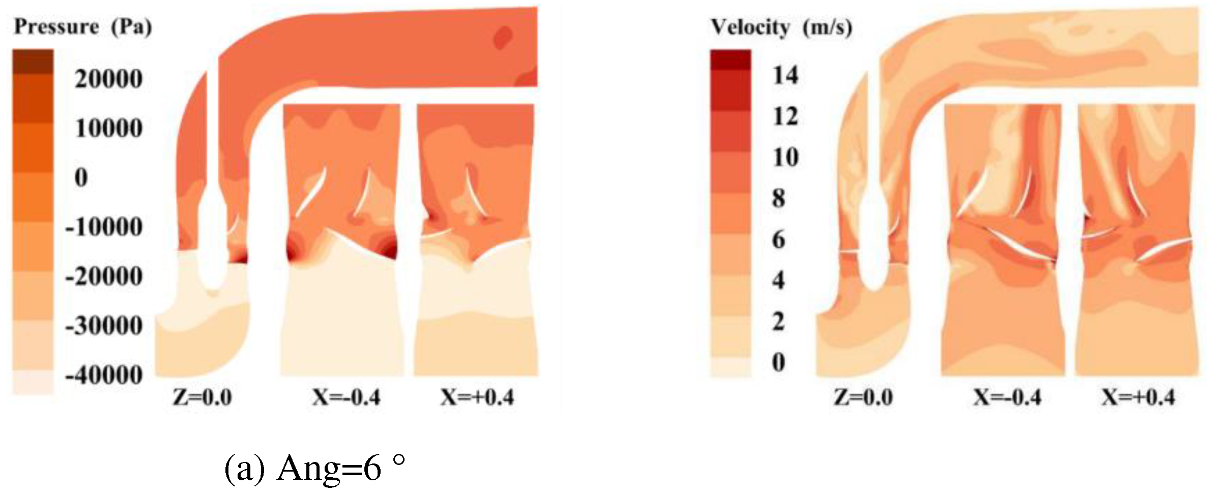
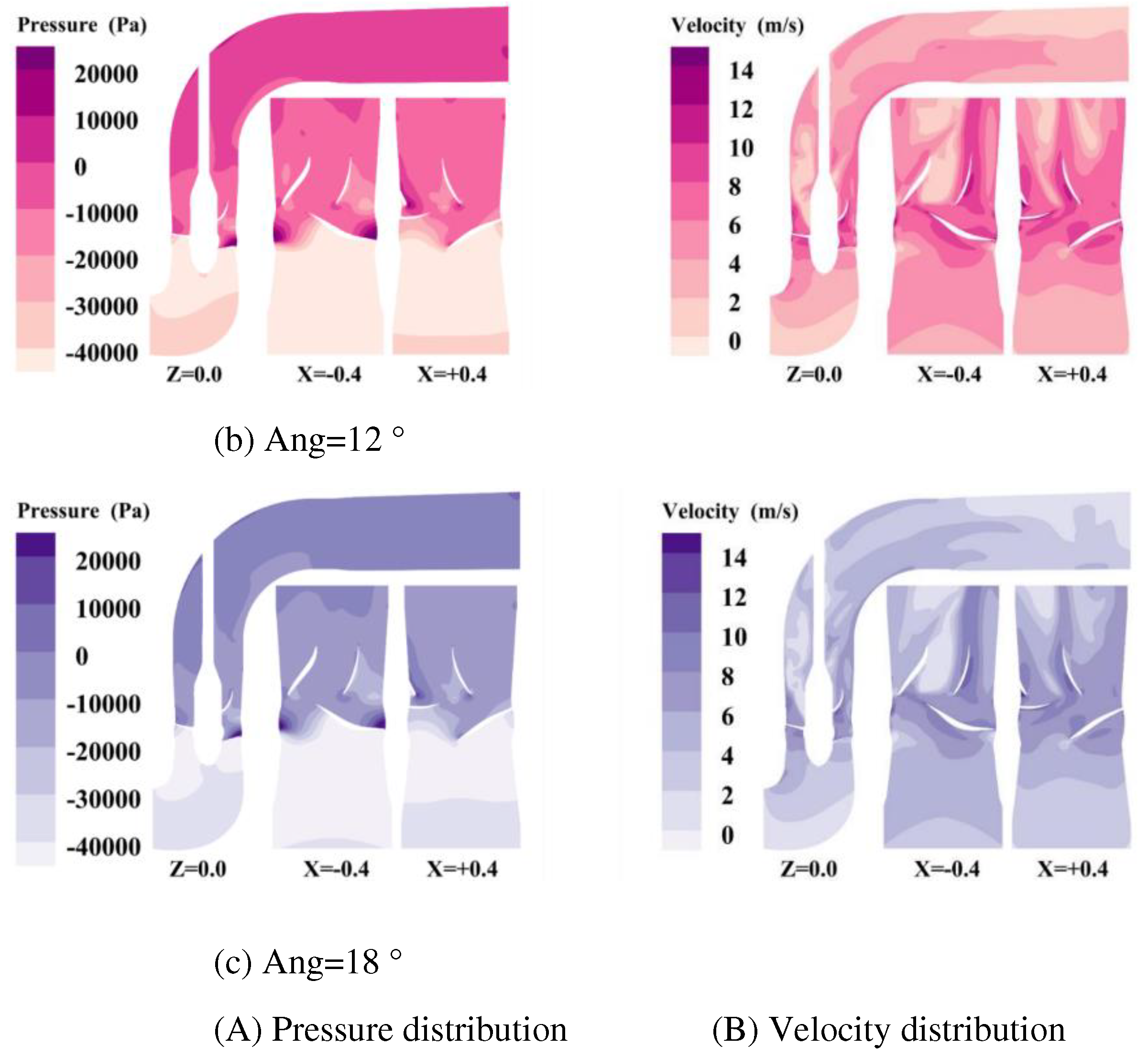
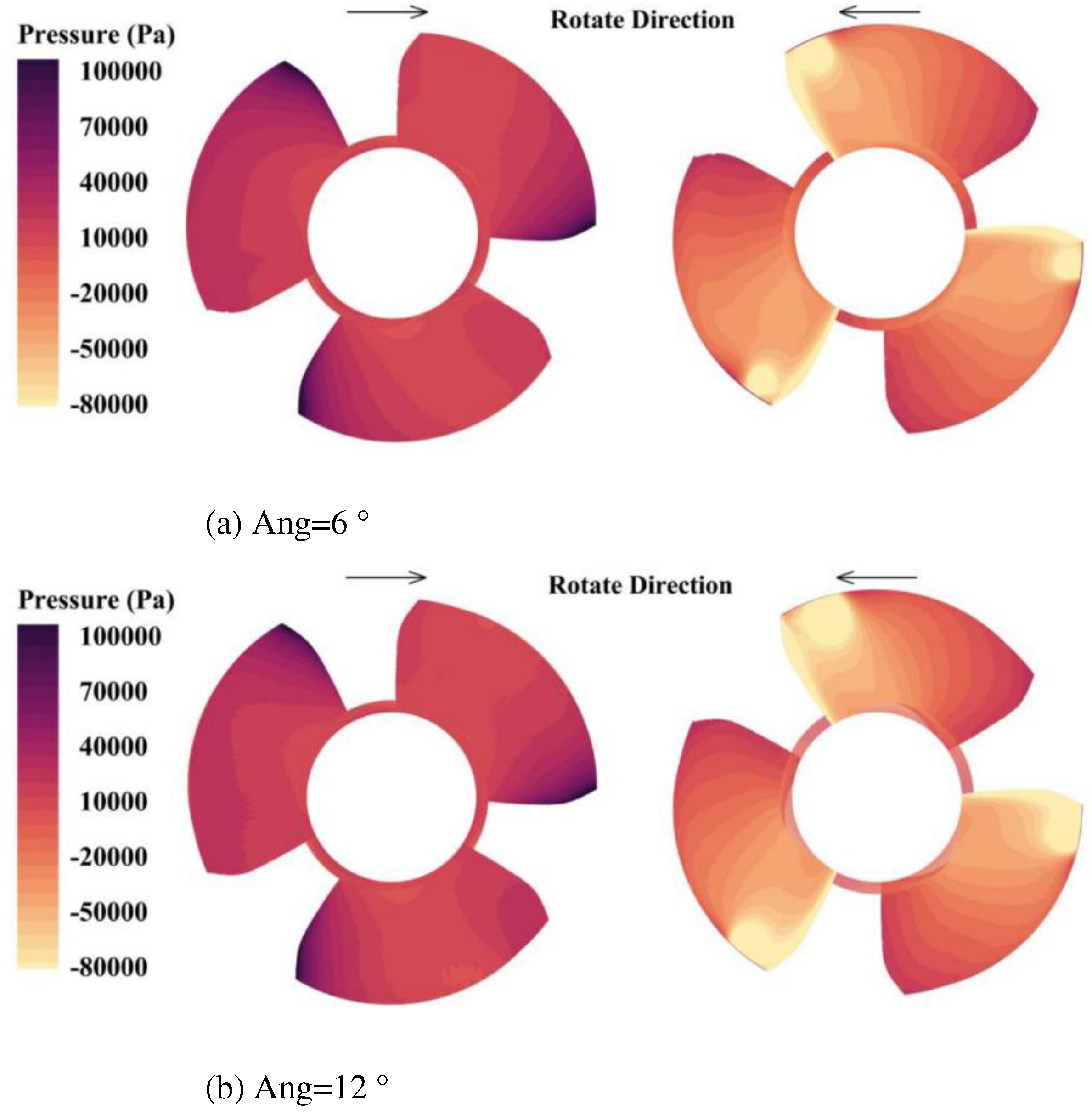
Aiming at the axial flow pump whose blade leading edge thickness is 11.4mm, the leading edge of the blade is oblique cut to different degrees, and three kinds of runners with different blade cutting degrees are designed. The appearance after cutting is shown in Figure 9. The angles between the leading edge and the radial direction of runner blades in different schemes are 6 °, 12 °, and 18 °.
When the blade angle becomes larger, the total area of the blade decreases, the throat area at the entrance of the blade increases slightly, the length of the airfoil bone line on the hub side increases, and the length of the flange wing bone line decreases.
As the output power of the runner will change with the change of the total area of the blade, it will bring unnecessary characteristic offset to the runner. To keep the output power of the runner stable, other control parameters should be considered at the same time to avoid great changes in the effective work area of the blade. To control the blade area, the cutting blade is properly extended to both sides of the inlet and outlet on the axial projection, and the gap between the total blade area of each scheme is narrowed. Finally, the total leaf area difference of each scheme is controlled within 0.01 m2 (about 0.4 % of the total area). The adjusted results are shown in Figure 10.
We use the comparative analysis method to comprehensively analyze the operation characteristics and flow field characteristics of the axial flow pump under different blade cutting angles and determine the better blade cutting angle.
After the blade is cut to different degrees, the head of the axial flow pump increases at first and then decreases. This shows that the hydraulic loss in the runner before and after cutting is not linearly coordinated with the designed cutting angle. The blade inlet pressure and outlet pressure decreased at first and then increased with the increase of blade angle, and the variation amplitude did not exceed 1.2 kPa, and the change of total pressure difference between the inlet and outlet of each scheme was very small. In terms of output power and efficiency, the runner with a blade cutting angle of 12 ° has the highest output shaft power and the lowest runner efficiency, but the overall efficiency is slightly higher than that of the 18 ° runner. it shows that there will be more significant differences in different parts of the internal flow field between the two.
With the increase of blade cutting angle, the negative pressure area below -40 kPa tends to decrease, which is beneficial to the passage of fish. The excessive area of high negative pressure in the suction chamber will increase the time for fish to withstand negative pressure injury. From the velocity distribution map, it can be seen that the cutting of the leading edge of the blade has a negative effect on the downstream flow pattern. The fluid enters the state of separation from the mainstream earlier, which makes the area surrounded by the velocity gradient line in the downstream region wider.
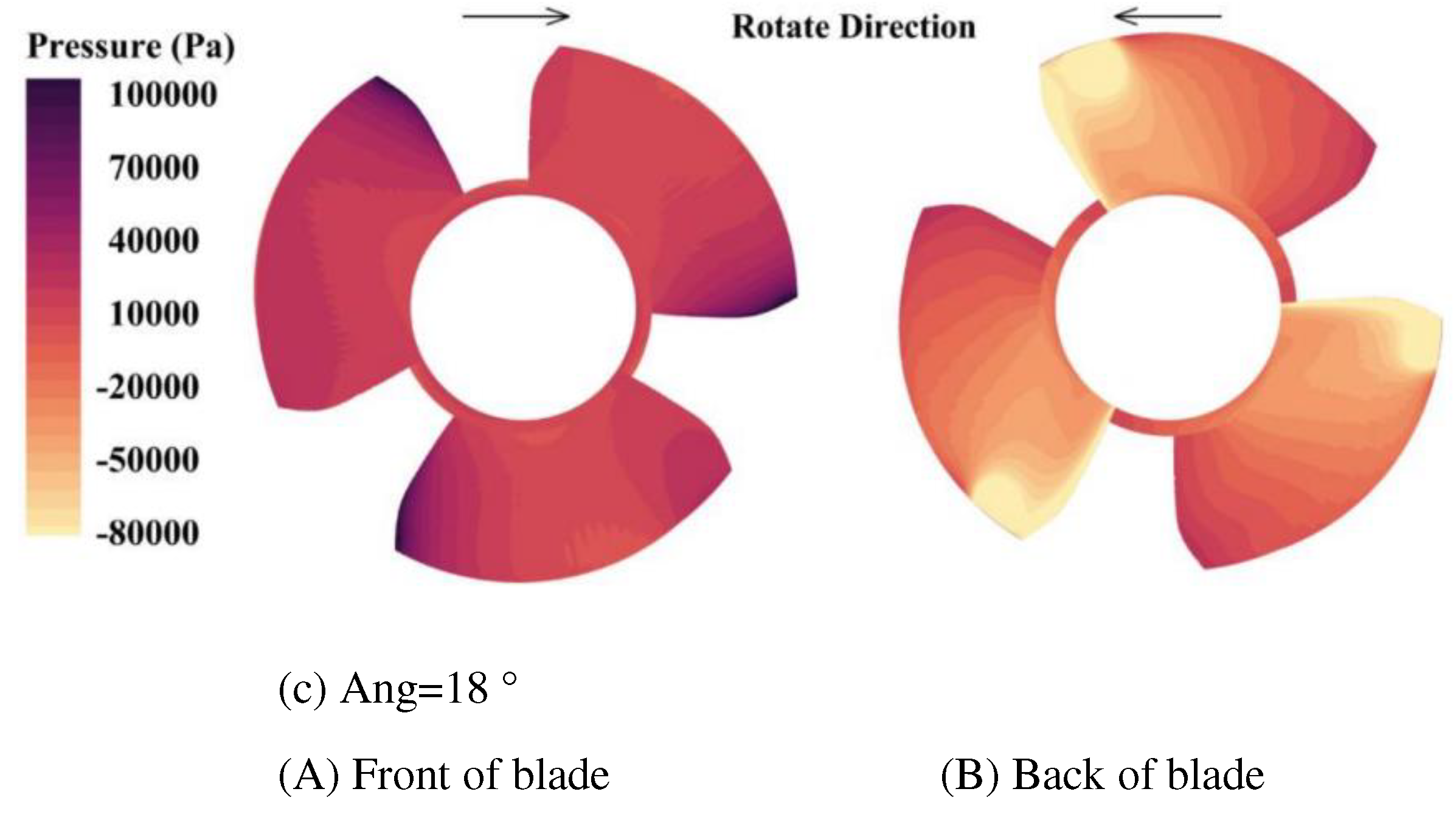
Figure 12. Pressure distribution on the front and back of blades at different cutting angles.
Preprints 86818 g012aPreprints 86818 g012b
The main difference in the pressure distribution between the front and back of the runner blade is the straightness of the isoline on the runner’s working face. After cutting, the isoline of the pressure distribution of the runner has an inflection point close to 120 °. On the suction surface of the blade, the area where the negative pressure on the suction surface of the blade with a cutting angle of Ang=12 ° is less than -80 kPa is slightly larger than that of the other two schemes.
The purpose of blade cutting is to reduce the probability of the fish hitting the leading edge of the blade and to make the fish move towards one side of the hub and reduce its linear speed. In terms of the operation efficiency of the axial flow pump and the flow pattern of the outlet channel, the scheme of cutting angle Ang=12 ° has a slight advantage. But in contrast, the negative pressure level of the suction chamber and the velocity gradient at the back end of the runner in the Ang=18 ° scheme are better, and the runner efficiency is better. Although the efficiency of the whole machine is slightly lower than the former, it is more in line with the design value of this paper to sacrifice a small part of the efficiency for the viability of fish. Therefore, the Ang=18 ° scheme is chosen in this section.

5. Fish-passing performance analysis of fish-friendly axial flow pump

5.1. Analysis on the behavior trajectory of Fish through Axial flow pump

For the modeling of real fish, the balance between the simplification of the model and the calculation effect should be considered. First of all, the connection gaps of fins, tails, and organs on the surface of fish bodies should be ignored. Secondly, the fish body model should be convenient for computer recognition and calculation, that is, the complexity of surface modeling of the fish body should be simplified, and the modeling of the fish body should be based on the surface composed of a simple conic curve.
Figure 13. A fish body model of two forms.
Preprints 86818 g013
According to the above modeling requirements, this paper establishes a fish body model with a 150 mm body length and only other fish body models with tail and belly shapes. Through trial calculation, it is found that the computational efficiency of OB fish is lower than that of SP fish under the lattice model which can restore the best analytical scale of fish surface shape. The effects of the two forms on the flow field and fish surface calculation results are not obvious. Therefore, SP fish with higher computational efficiency is selected as the fish body model object for subsequent calculation in this paper.
After entering the channel, the fish pass through the inlet channel, runner, guide vane, outlet channel, and other areas one by one. Due to the continuous work done by the pump blade, the kinetic energy of the flow body increases sharply, which makes the movement trend of fish very easy to be affected by the fluid in the pump. Therefore, the change of the flow field characteristics caused by the change of the pump structure is bound to affect the trajectory of the fish. This section combines the LES-IB-LBM method to explore the influence of the change of flow field characteristics on the passage of fish.
When simulating the fish body passing through the fish-friendly axial flow pump, a total of three fish are placed at different radial positions at a certain section of the intake passage of the axial flow pump at the initial time, and the motion trajectories of the fish passing through the runner area of the axial flow pump and the water guide mechanism are calculated. the difference between the fish-friendly pump and the prototype pump affecting the passage trajectory of the fish body before and after the optimization design is analyzed.
Figure 14. Schematic diagram of different positions of fish through axial flow pump.
Preprints 86818 g014
The speed and posture of the three fish in the fish-friendly pump are different. The three fish changed the direction of the fish once at the three moments caught. The change in direction of the small yellow croaker is mainly due to its proximity to the curved surface of the hub, while the small red fish and the small blue fish have a very obvious movement to the hub side in the radial position. All three fish no longer maintain the circular motion of equal angular velocity, which makes the outermost red fish, which should have a higher linear velocity, lag significantly behind the other two fish near the inside after entering the runner.
After the fish body enters the water guide mechanism, what is different from the compact and consistent motion posture in the runner is that with the increase of motion space, the increase of motion speed, and the possible influence of dynamic and static interference, the motion trend of the three fish is basically inconsistent. The three fish always move near the hub side, still keeping the blue fish in the lead, the red fish lagging. The movement distance of the three fish can ensure that their different walls collide head-on.

5.2. Comparative analysis on the mortality of fish subjected to blade impact

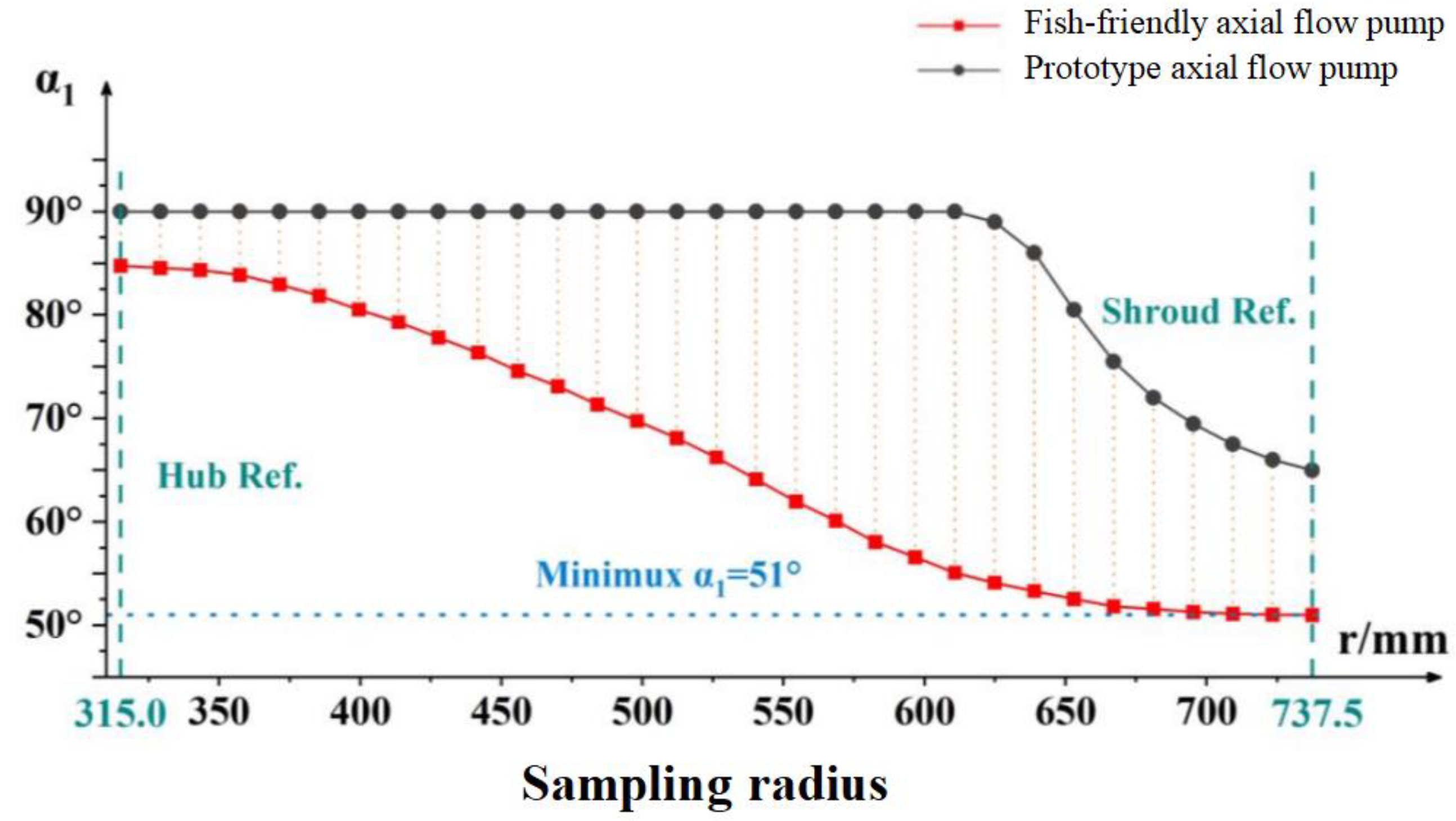
The impact death probability of fish consists of two parts: impact probability and death index. The impact probability can be determined directly by the parameters of the fish body and runner. In order to obtain the death index, the impact velocity v s r , α 1 , α 2 should be calculated first. α 1 can be exported at different radius r by runner design software. The scatter relationship between the two is shown in Figure 15.
In this paper, the polynomial function is used to fit the r α 1 data of the runner blade of the fish-friendly axial flow pump. The calculation equation obtained from the fitting model is:
α 1 = 22.34943 + 0.79326 r 0.00181 r 2 + 1.18296 × 10 6 r 3
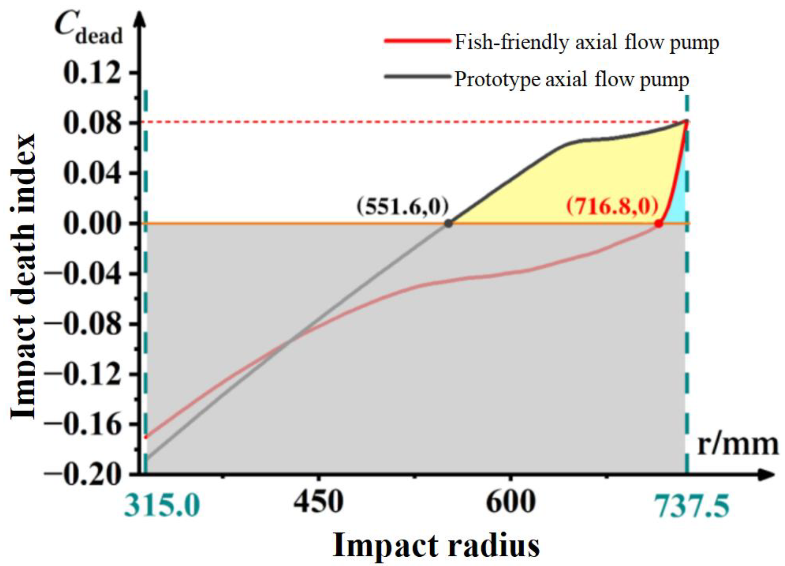
The distribution curve of the impact death index of the runner blade of the axial flow pump before and after optimization is shown in Figure 16.
The optimized axial flow pump runner is close to the runner without damage. The calculation and verification of the original data points before fitting show that when the radius of the impact point is 723.43 mm, the impact velocity is 4.807 m/s and the death index is less than 0.0015. When the radius is less than 716.8 mm, the impact velocity is less than 4.8 m/s. At this time, there is no need to discuss the specific value of the blade impact probability, and the fish will not be killed by hitting the leading edge of the blade. The impact death rate can be obtained by the integral of the impact death index for the radius r. Therefore, the yellow and blue shadow area in the figure can be used to roughly estimate the total impact mortality ratio of the axial flow pump runner before and after optimization, and the ratio before and after optimization is close to 7:1.

5.3. Comparative analysis of fish subjected to pressure and shear damage

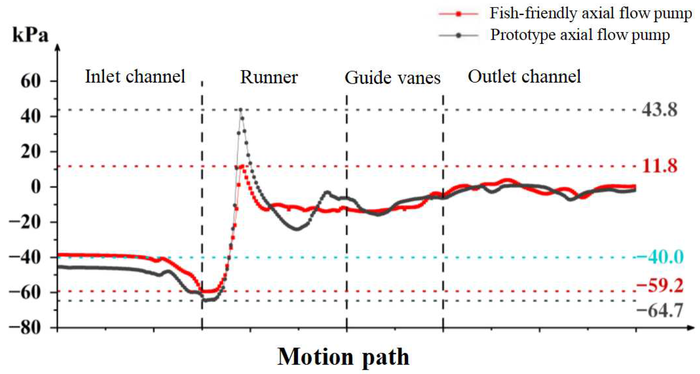
From the point of view of the variation of the average pressure of the fish body with the motion path in Figure 17, the lowest negative pressure in the inlet section of the fish-friendly axial flow pump is higher than -40 kPa runner is -59.2 kPa. The inlet passage of the prototype pump is lower than -40 kPa and the lowest negative pressure is -64.7 kPa. The average and maximum negative pressure of the fish friend pump is higher than that of the prototype pump. The maximum positive pressure on the front of the blade on the path of the fish is 11.8 kPa, which is significantly lower than that of the prototype axial flow pump at 43.8 kPa. This shows that the level of pressure gradient caused by the pressure change of the fish body in the fish-friendly pump is lower, so it is less vulnerable to pressure gradient damage. This means that the degree of negative pressure damage to the passing fish body is reduced, which is more beneficial for the fish to pass through the axial flow pump.
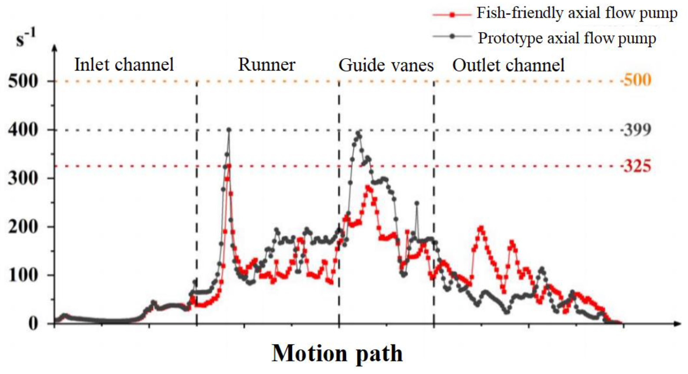
Literature studies show that the main evaluation index of shear damage of fish in a strong shear environment is the shear strain rate. When the shear strain rate is less than 500 s-1, it is considered that the fish will not be subjected to shear damage. Figure 18 shows the change of the average shear strain rate on the body surface as the fish passes through the axial flow pump. Both the prototype pump and the fish-friendly pump reach the maximum shear strain rate at the front of the runner. As far as the situation seen in the diagram is concerned, when the fish body passes through the prototype axial flow pump and the fish-friendly axial flow pump, it does not reach the damage threshold of 500 s-1, so it will not be subjected to shear damage. The actual situation still needs to be analyzed by the distribution of shear strain rate on the fish surface.
Thus it can be seen that changing the blade thickness and cutting angle can effectively reduce the impact damage to fish. This is consistent with Amral’s view [37] that the non-right angle between the leading edge of the blade and the trajectory of the fish can reduce the strike speed or damage rate. The pressure injury of fish is mainly negative pressure injury, Shao et al. [7,8] also reached a similar conclusion. Therefore, the impact damage caused by blades should be given priority in the design of fish-friendly hydraulic machinery. Klopries [38] based on CFD streamline assessment of Kaplan turbines also found that collision is the most serious cause of fish death. Secondly, the negative pressure and pressure gradient need to be considered, while the priority of shear stress injury is slightly lower.

6. Conclusion

In this paper, taking a common axial flow pump as the research object, the fish pressure damage experiment was carried out, and the survival conditions and corresponding survival thresholds of several kinds of fish under different pressures were explored, which provided an effective evaluation basis for the later optimization design. Based on the impact theory, a fish-friendly axial flow pump is designed, which greatly reduces the mortality of the fish passing through the axial flow pump channel and ensures the high hydraulic performance of the pump.
The main contents and related achievements of the full text are summarized as follows:
  • Using the experiment device which is suitable for simulating the internal pressure of hydraulic machinery, the survival conditions of different species of fish under different pressure thresholds are obtained. Several typical pressure thresholds that fish may bear in the axial flow pump were simulated, and the damage situation and damage mechanism of fish after pressure injury were further studied. The survival threshold of wild crucian carp and yellow catfish is -40kPa. Other fish species should not be subjected to negative pressure. Therefore, this paper establishes -4kPa as the low-pressure damage threshold, which is used as a reference to analyze the probability of fish damage caused by hydraulic turbines.
  • Based on the runner design method and blade impact model of the axial flow pump, a fish-friendly axial flow pump is designed. The structural design of the axial flow pump runner is guided by the variables in the blade impact model, and the fish-friendly runner with high hydraulic performance and low impact mortality is obtained by using hydraulic performance, pressure, and shear rate damage as criteria. The runner whose leading edge thickness is 11.4mm is determined. This scheme can reduce the impact probability of the blade on the fish, ensure that the efficiency of the original runner is 98.4%, and have a more fish-friendly suction chamber negative pressure level than the 17.4mm runner. The runner with an inlet cutting angle of 18 ° is determined. The hydraulic performance, guiding effect, negative pressure performance, and velocity gradient performance of this scheme are better than those of 12 ° runner.
  • Based on the efficient boundary calculation ability of the moving object of the LES-IB-LB method, the upward trajectory of three fish through the axial flow pump is simulated. The fish-passing performance of the prototype pump and fish-friendly axial flow pump were qualitatively and quantitatively analyzed. It is calculated that when the impact radius is less than 716.8 mm, the impact between the fish and the runner will not cause death. The ratio of total impact mortality of axial flow pump runner before and after optimization is close to 7:1. The pressure damage analysis shows that the average negative pressure on the body surface of the fish passing through the fish-friendly axial flow pump is higher than the survival threshold -40 kPa, and the negative pressure is lower than -40 kPa only in 0.13 s of the runner, while the lowest negative pressure -59.2 kPa is still higher than -64.7 kPa of the prototype axial flow pump, so the fish-friendly axial flow pump can reduce the negative pressure damage of fish. The shear damage analysis shows that the fish will not be damaged by shear in the prototype pump and the fish-friendly pump.

Corresponding author

Chunxia Yang (1988-), Ph.D., Associate professor. Her research interests include the optimization design of eco-friendly hydraulic machinery, solid-liquid two-phase flow, and the development and utilization of Marine energy, E-mail: yangchunxia@hhu.edu.cn.

Foundation Item

Key Technologies Research and Development Program (2019YEF0105200); Central University Basic Research Fund of China (B210202060); the Fundamental Research Funds for the Central Universities(B220202005).

Nomenclature

τ the relaxation time, s
Pimpact the probability of impact between the fish and the blade
tfish the time for the fish to pass through the leading edge of the blade
hfish the correction coefficient of the effective length of the fish
tblade the time for the blade to walk through a leaf spacing
Cdead the fish impact death index
Lfish the length of the fish body, m
D the thickness of the leading edge of the blade, m
Vs the impact velocity

References

  1. Thompson, A.M., Glasgow, J., Buehrens, T., et al. 2011. Mortality in juvenile salmonids passed through an agricultural Hidrostal pump. Fish. Manag. Ecol. 18 (4), 333–338. [CrossRef]
  2. Liu, C. Global migratory fish is facing extinction crisis. Ecological economy, 2021, 37 (01): 5-8.
  3. Liu, X. Research on the predicament and countermeasures of domestic fish road development. Guangxi Quality Supervision Guide, 2018, 1 (06): 24.
  4. Amaral S.V. Development and application of fish-friendly hydraulic turbine. KuaiBao of Water Conservancy and Hydropower, 2012: 33 (4): 34-37.
  5. Abernethy, C.S., Amidan, B.G., Eada, G.F. Simulated passage through a modified kaplan turbine pressure regime: A Supplement to ‘Laboratory Studies of the Effects of Pressure and Dissolved Gas Supersaturation on Turbine-Passed Fish. European Journal of Operational Research, 2002,73(1): 1-16. [CrossRef]
  6. Yang, C.X., Zheng, Y., Zhang, Y.Q., et al. Review on design and research of fish-friendly hydraulic turbines. Engineering Science, 2018,20(03): 96-101.
  7. Aode, M., Ma, X.j., Liu, Y. New concept of parent fish turbine design. Water Resources and hydropower Letters, 2001(4): 1-5.
  8. Shao, Q., Li, H.F., Wu, Y.L., et al. Simulation test of Pressure gradient Change in hydraulic machinery on fish damage. Chinese Journal of Mechanical Engineering, 2002(10): 7-11.
  9. Shao, Q., Li, M., Wu, Y.L., et al. Stress damage simulation of carp and grass carp in hydraulic machinery. Chinese Journal of Engineering Thermophysics, 2003(06): 954-957.
  10. Cada G. F., Bevelhimer, M. S. 2011. Attraction to and avoidance of instream hydrokinetic turbines by freshwater aquatic organisms. Oak Ridge Nati onalLaboratory,May. [CrossRef]
  11. Abernethy C.S., Amidan B.G. Laboratory studies of the effects of pressure and dissolved gas supersaturation on turbine-passed fish. office of scientific & technical information technical reports, 2001. [CrossRef]
  12. Cada, G., Loar, J., Garrison, L., et al. Efforts to reduce mortality to hydroelectric turbine-passed fish: Locating and Quantifying Damaging Shear Stresses. Environmental Management, 2006,37(6): 898-906. [CrossRef]
  13. Neitzel, D.A., Rishmond, M.C., Dauble, D.D., et al. Laboratory studies on the effects of shear on fish. Reports, 2000. [CrossRef]
  14. Neitzel, D.A., Dauble, D.D., Cada, G.F., et al. Survival estimates for juvenile fish subjected to a laboratory-generated shear environment. Transactions of the American Fisheries Society (1900), 2004,133(2): 447-454. [CrossRef]
  15. Lai X.D., Digital design and manufacture of vane fluid machinery. 2007.
  16. Lai X.D., Xu Y. Dynamic analysis and application of vane hydromechanical. 2017.
  17. Cook T.C., Hecker G.E., Faulkner H.B., et al. Development of a more fish-tolerant turbine runner, advanced Hydropower turbine project. Development of a More Fish Tolerant Turbine Runner - Advanced Hydropower Turbine Project, 1997.
  18. Hogan T.W., Cada G.F., Amaral S.V. The status of environmentally enhanced hydropower turbines. Fisheries, 2014, 39(4): 164-172. [CrossRef]
  19. Franke G.F., Webb D.R., Fisher R.K. Development of environmentally advanced hydropower turbine system concepts. Office of Scientific & Technical Information Technical Reports, 1997.
  20. Liao C.L., Lu L., Li T.Y., et al. Advance on the research and application of fish friendly turbine; Proceedings of the Proceedings Of The 35TH IAHR World Congress Vols I And II, 2013, 2013.
  21. Brown S. Innovations in turbine design and fish protection at Wanapum. International Journal on Hydropower & Dams, 2006, 13(4): 71-72.
  22. Loiseau F., Davidson R.A., Ouston M. Fish environment & new turbines design; proceedings of the 23rd IAHR Symposium-Yokohama, October 2006.
  23. David T., Mahar J.R. A cost effective and environmentally sustainable approach to retrofitting existing dams for hydroelectric power generation. Waterpower, 2009.
  24. Li H.F., Wu Y.L., Wang Z.W., et al. Experimental study on a new environment-friendly upflow turbine. Journal of Hydropower, 2002, 1 (1): 89-95.
  25. Pan, Q., Zhang, D.S., Shi, W.D. Optimization design of fish-friendly axial flow pump based on blade impact model. Transactions of the Chinese Society for Agricultural Machinery,2015,46(12):102-108.
  26. Pan, Q., Shi, W.D., Zhang, D.S., et al. Fish-friendly design and fish survival prediction of axial flow pumps for pumping stations. Journal of Drainage and Irrigation Machinery Engineering, 2017,35(001): 42-49. [CrossRef]
  27. Halliday I., Hammond L.A., Care C.M., et al. Lattice Boltzmann equation hydrodynamics. Physical Review E, 2001, 64(1): 18-20. [CrossRef]
  28. Chikatamarla S.S., Karlin I.V. Lattices for the lattice Boltzmann method. Physical Review E, 2009, 79(4). [CrossRef]
  29. Wu J.Y., Cheng Y.G., Zhang C.Z., et al. A high precision immersion boundary-lattice Boltzmann fluid-solid coupling scheme is used to simulate the free settlement motion of a two-dimensional rigid body. Journal of Sichuan University (Engineering Science Edition), 2016, 48 (1): 29-34.
  30. Li S.Y., Cheng Y.G., Zhang C.Z. IB-LB coupling scheme simulates 3-D transient flow of tubular turbine. Journal of Huazhong University of Science and Technology (Natural Science Edition), 2016, 44 (01): 122,127.
  31. Li J. Study on damage mechanism of passing fish in tubular turbine; Xi’an University of Technology, 2020.
  32. Zhu G.J., Li J., Feng J.J. Research on casualty characteristics of fish in tubular turbine based on IB-LBM method. Journal of Physics Conference series, 2020, 1549(4): 42135. [CrossRef]
  33. Quaranta E., Wolter C. Sustainability assessment of hydropower water wheels with downstream migrating fish and blade strike modeling. Sustainable energy technologies and assessments, 2021, 43(1). [CrossRef]
  34. Stoltz U., Geiger F., Tuhtan J. A., et al. Influence of operation modes and fish behavior on fish passage through turbines; proceedings of the 30th IAHR Symposium on Hydraulic Machinery and Systems (IAHR), Electr Network, F 2021Mar 21-26, 2021.
  35. Mueller M., Sternecker K., Milz S., et al. Assessing turbine passage effects on internal fish injury and delayed mortality using X-ray imaging. Peer J, 2020, 8(1): 18-20. [CrossRef]
  36. Saylor R., Sterling D., Bevelhimer M.S., et al. Within and among fish species differences in simulated turbine blade strike mortality: Limits on the Use of Surrogacy for Untested Species. Water, 2020, 12(3). [CrossRef]
  37. Amaral, S.V., Watson, S.M., Schneider, A.D., et al., 2020. Improving survival: injury and mortality of fish struck by blades with slanted, blunt leading edges. EcoHydraul. 5(2), 175–183. [CrossRef]
  38. Klopries, E.M., Schüttrumpf, H., 2020. Mortality assessment for adult European eels (Anguilla Anguilla) during turbine passage using CFD modeling. Renew. Energy 147, 1481–1490. [CrossRef]
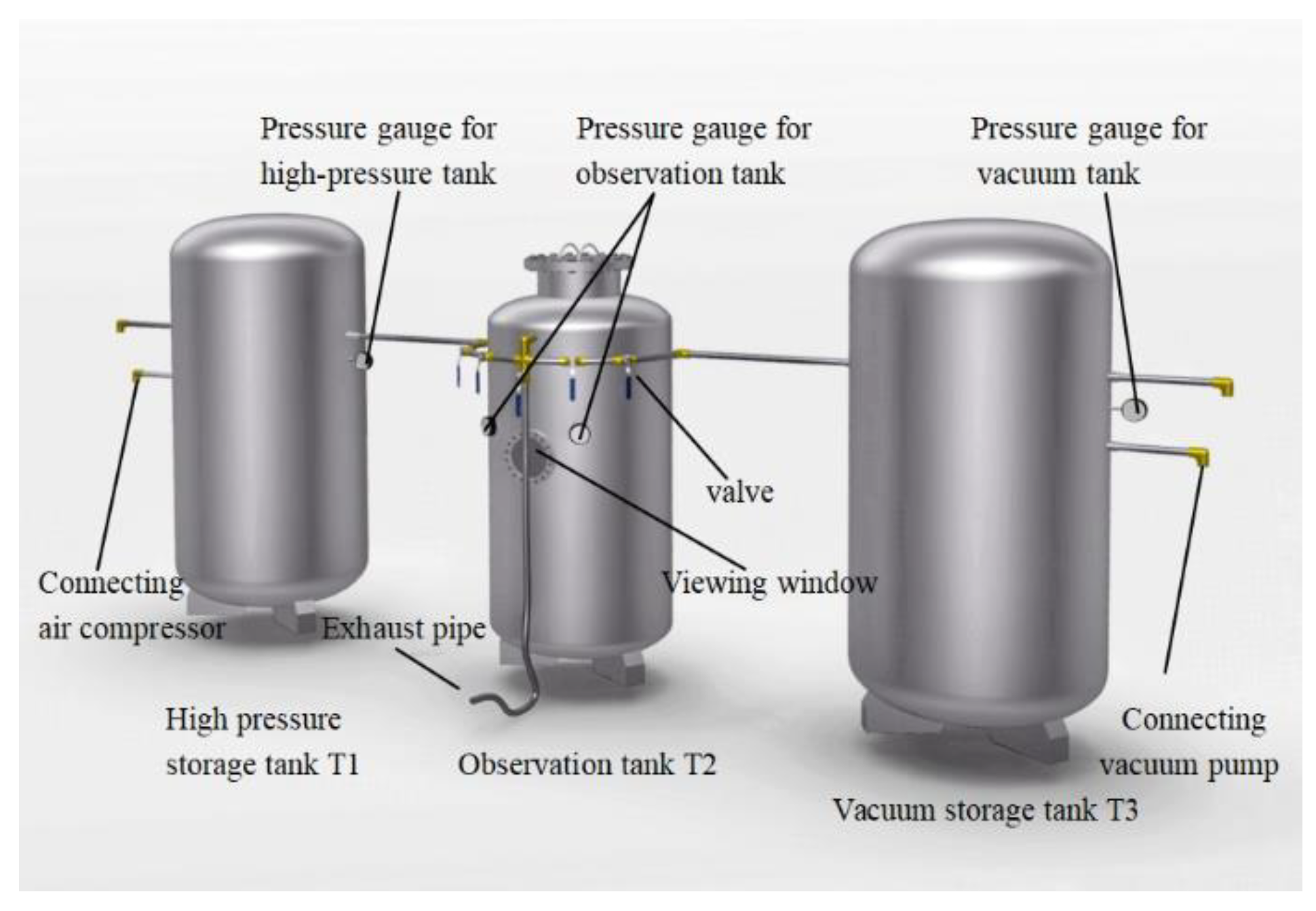
Figure 1. Schematic diagram of pressure damage experiment device.
Preprints 86818 g001
Figure 2. Diagram of experimental fish.
Preprints 86818 g002
Figure 3. Three-dimensional model of the full channel of axial flow pump.
Preprints 86818 g003
Figure 4. Verification of irrelevance of the number of lattices.
Preprints 86818 g004
Figure 5. Schematic diagram of lattice structure scheme.
Preprints 86818 g005
Figure 6. Different leading edge thickness of blade.
Preprints 86818 g006
Figure 7. Cross-sectional velocity and pressure distribution of axial flow pump with different thickness.
Preprints 86818 g007aPreprints 86818 g007b
Figure 8. Pressure distribution on the front and back of the blade under different thickness.
Preprints 86818 g008aPreprints 86818 g008b
Figure 9. Different blade cutting angles.
Preprints 86818 g009
Figure 10. Schematic diagram of axial projection shape of blade.
Preprints 86818 g010
Figure 11. Cross-section velocity and pressure distribution of axial flow pump at different cutting angles.
Preprints 86818 g011aPreprints 86818 g011b
Figure 15. Relationship between r α 1 scatter points at the leading edge of two kinds of runner blades.
Preprints 86818 g015
Figure 16. Cdead distribution of impact death index obtained from fitting equation.
Preprints 86818 g016
Figure 17. Variation curve of average pressure on the whole flow channel of fish-body axial flow pump.
Preprints 86818 g017
Figure 18. Variation curve of average shear strain rate on the whole flow channel of fish axial flow pump.
Preprints 86818 g018
Table 1. Fish damage after high-pressure experiment.
Experimental laber Fish species Pressure threshold(Mpa) Increase pressure time(s) Increase pressure rate(kpa/s) The number of abnormal fish The number of dead fish The proportion of dead fish(%) The proportion of surviving fish(%)
0C Cultured crucian carp 0.101 0 0 3 0 0 100
0W Wild crucian carp 6 18 18 82
0Y Yellow catfish 0 3 3 97
1C Cultured crucian carp 0.34 24 13.6 18 20 20 80
1W Wild crucian carp 6 18 18 82
1Y Yellow catfish 0 4 4 96
2C Cultured crucian carp 0.68 48 13.6 17 72 72 28
2W Wild crucian carp 3 19 19 81
2Y Yellow catfish 1 8 8 92
Table 2. Fish damage after low-pressure experiment.
Experimental laber Fish species Pressure threshold(Mpa) Increase pressure time(s) Increase pressure rate(kpa/s) The number of abnormal fish The number of dead fish The proportion of dead fish(%) The proportion of surviving fish(%)
0C Cultured crucian carp 0.101 0 0 3 0 0 100
0W Wild crucian carp 6 18 18 82
0Y Yellow catfish 0 3 3 97
3C Cultured crucian carp -0.02 6 3.33 12 76 76 24
3W Wild crucian carp 6 6 6 94
3Y Yellow catfish 2 13 13 87
4C Cultured crucian carp -0.04 12 3.33 0 100 100 0
4W Wild crucian carp 1 19 19 81
4Y Yellow catfish 6 37 37 63
5C Cultured crucian carp -0.08 24 3.33 0 100 100 0
5W Wild crucian carp 18 78 78 22
5Y Yellow catfish 15 70 70 30
Table 3. Main parameters of the wheel model.
Parameter Value
Rated headb Hr (m) 6.0
Rated speed nr (r/min) 300
Rated discharge Qr (m3/s) 8.0
Runner diameter D1 (mm) 1475
Number of runner blade Nb 3
Number of guide vane Ngv 5
Table 4. Operating parameters of axial flow pump with different leading edge thickness of blade.
Leading edge thickness of blade Discharge Head Average pressure at inlet and outlet of runner Shaft power Runner efficiency Machine efficiency
Thk(mm) Q(m3/s) H(m) P1(kPa) P0(kPa) ΔP(kPa) N(kw) η(%) η(%)
5.6 8.01 6.01 -44.5 14.3 58.8 523.4 90.12 75.68
11.4 8.02 5.91 -45.9 11.9 57.9 518.8 89.38 74.50
17.4 8.02 5.83 -47.3 9.8 57.1 514.8 88.87 73.59
Table 5. Operating parameters of axial flow pump with different blade cutting angles.
Blade cutting angles Discharge Head Average pressure at inlet and outlet of runner Shaft power Runner efficiency Machine efficiency
Ang(°) Q(m3/s) H(m) P1(kPa) P0(kPa) ΔP(kPa) N(kw) η(%) η(%)
6 8.02 5.91 -45.9 11.9 57.9 518.8 89.38 74.50
12 8.01 5.95 -46.0 12.2 58.3 529.6 88.20 72.62
18 8.02 5.90 -44.8 12.8 57.6 523.0 88.33 71.38
Disclaimer/Publisher’s Note: The statements, opinions and data contained in all publications are solely those of the individual author(s) and contributor(s) and not of MDPI and/or the editor(s). MDPI and/or the editor(s) disclaim responsibility for any injury to people or property resulting from any ideas, methods, instructions or products referred to in the content.
Copyright: This open access article is published under a Creative Commons CC BY 4.0 license, which permit the free download, distribution, and reuse, provided that the author and preprint are cited in any reuse.
Alerts
Prerpints.org logo

Preprints.org is a free preprint server supported by MDPI in Basel, Switzerland.

Subscribe

© 2025 MDPI (Basel, Switzerland) unless otherwise stated