1. Introduction
A hypersonic vehicle refers to an aircraft that cruises in or across the atmosphere at a speed of more than
Ma5. Scramjet, one of the main engine forms of the hypersonic vehicle, has a simple structure, does not need to carry oxidant, and can take off and land horizontally[
1,
2]. Scramjet has four parts: inlet, isolator, combustor, and nozzle. The nozzle is the main component that provides thrust and lift. Given that a hypersonic vehicle has a wide flight envelope, the nozzle performs well in a large range of nozzle pressure ratio (NPR), and the area ratio of nozzle outlet and inlet usually reaches 10. Researchers [
3] showed that a symmetric nozzle cannot satisfy such application requirements; thus, the nozzle with an asymmetric geometry structure is developed. In addition, the nozzle’s geometry should be constrained because of the highly integrated characteristics and design requirements of a hypersonic vehicle [
4]. The height of the nozzle outlet affects the NPR at the design point, the aircraft’s windward drag, and the nozzle’s net thrust. Therefore, the nozzle height should be constrained directly.
Rao [
5] derived the maximum thrust theory with the method of calculus of variations to improve the nozzle aerodynamic performance. This method is widely used in the nozzle design of rocket engines. Lu [
6] proposed a design method for an asymmetric nozzle based on the streamline tracing method and maximum thrust theory. Results showed that compared with the nozzle with straight walls, the stream-traced nozzle obtains a 2.7% increase in thrust and a 69.5% increase in lift. Lv [
7] proposed an asymmetric nozzle design method based on the method of characteristics (MOC) under geometric constraints and studied the influence of flap length on nozzle performance. Their proposed method can increase the axial thrust coefficient, lift, and pitching moment of the nozzle by 5.5%, 1098.2%, and 20.3%, respectively. Yu [
8] proposed an inverse design method of the nozzle based on maximum thrust theory and MOC, thereby improving the thrust coefficient, lift, and pitching moment by 31.8%, 201%, and 56.6%, respectively. Subsequently, Yu [
9] developed a nozzle design method based on the inverse design method, which can constrain the absolute size and position of the inlet and outlet. Chen [
10] proposed a design method for the 2D thrust-optimized single expansion ramp nozzle(SERN), which increased the axial thrust by 6.38% and the lift by 180%, further revealing the relationship between aerodynamic performance and geometric design conditions.
The nozzle designed using MOC usually has good aerodynamic performance. However, its length is extremely large, which is not conducive to the integrated designs of the aircraft and the engine. Researchers proposed the theory of minimum length nozzle and truncated the nozzle to shorten the nozzle length further. Argrow [
11] developed minimal length nozzle theory. However, the ideal expansion nozzle designed by this method is still extremely long. Thus, the geometric constraints of the thrust nozzle cannot be satisfied. Shyne [
12] proposed an improved method, enabling the nozzle to satisfy the size constraints and reduce the weight. The results showed that the truncation requirements should make a trade-off between the weight and performance loss of the nozzle. Hoffman [
13] proposed a design method for the compressed truncated nozzle, which can effectively shorten the nozzle length. The performance difference between the compressed truncated nozzle and the Rao nozzle is only 0.04%–0.34%.
In the present study, a design method for 2D SERN is proposed under height constraint. The accuracy and rationality of CFD simulation are confirmed in Section 0. The design method for SERN is introduced in
Section 3. The design parameters are studied parametrically, and the influences of their mechanisms on nozzle geometry and performance are studied in
Section 4. In
Section 5, the performance of the nozzle designed using the proposed design method and that designed using the traditional truncated design method are compared under the same design and off-design points to confirm the superiority of the proposed design method.
2. Numerical Approaches
The commercial software ANSYS Fluent is used to obtain the flow fields and the aerodynamic performance of the nozzles. The governing equations are briefly described as follows:
where
ρ,
u,
v,
p,
τ, and
e represent the density,
x-direction velocity component,
y-direction velocity component, pressure, shearing stress, and total energy per unit mass, respectively. The inviscid flux is computed using the Roe flux-difference splitting scheme on the control surfaces. The second-order upwind scheme is used to discretize the governing equations, and the method based on the least squares cell is used to compute the gradient. During the calculation, the mass flow through the inlet and the force on the ramp and flap are used to monitor the convergence. The calculation can be considered convergent when the above calculation results remain constant with the increase in iteration steps. In the numerical simulation, the boundary conditions (i.e., pressure inlet, pressure outlet, and pressure far field) are adopted.
2.1. Validation of numerical method
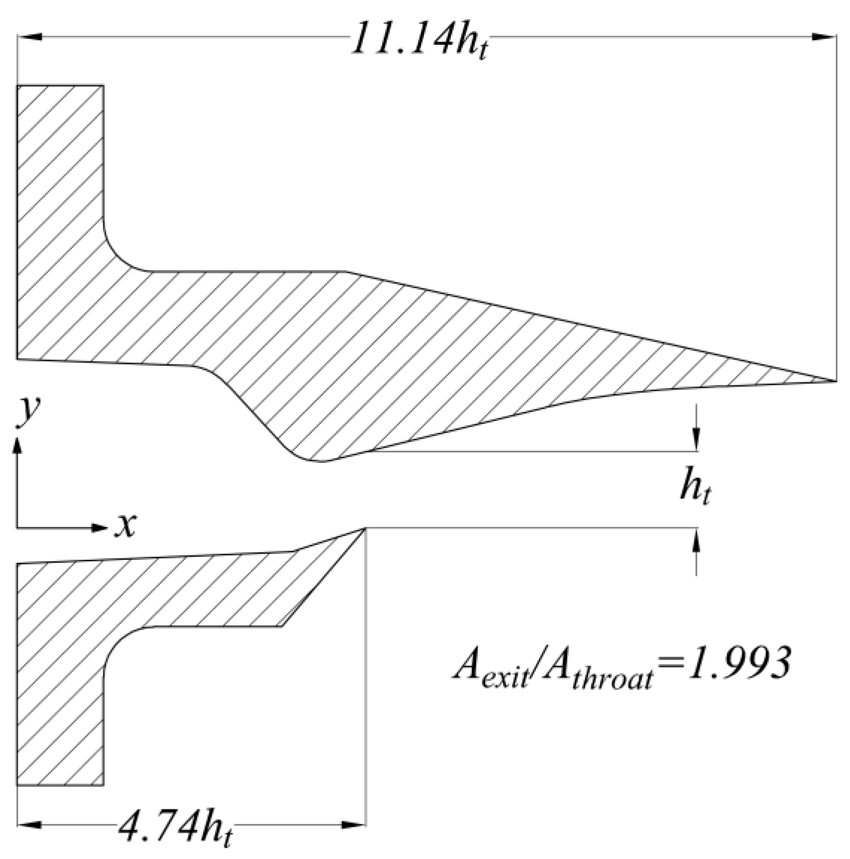
The SERN experimental model of NASA is used to verify the reliability and accuracy of the numerical simulation. The nozzle named GR3 in reference [
14] is selected. The area ratio of the outlet to the inlet is 1.993, and the NPR is set to 8.571. The geometric model of the nozzle is shown in
Figure 1.
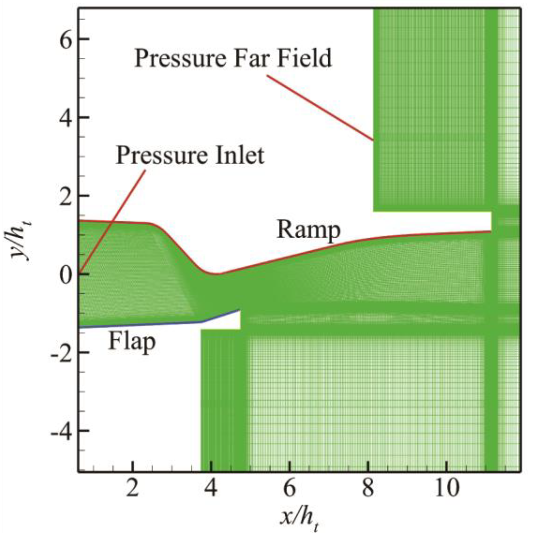
Figure 2 shows the computational grid, and
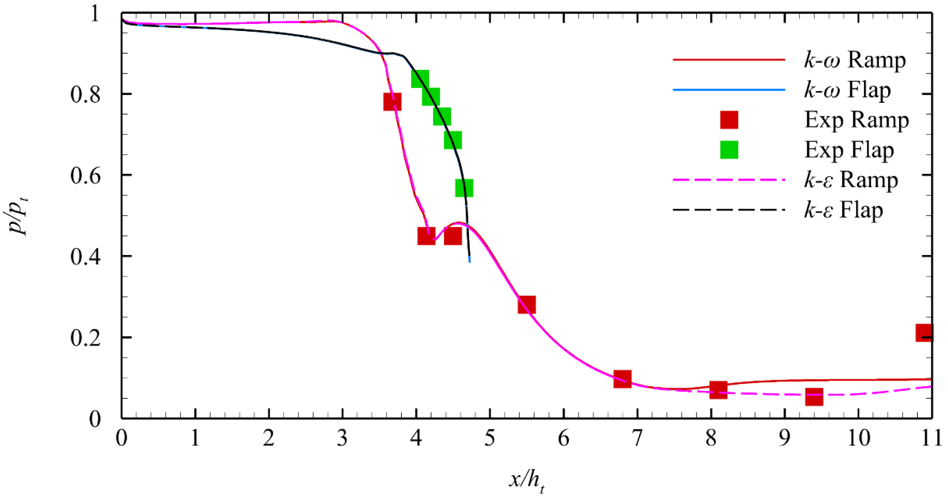
Figure 3 shows the comparison of the numerical results of the normalized pressure distribution on the ramp and flap between CFD and the experiment. Two turbulence models,
k-
ω SST and realizable
k-
ε, are used in CFD simulation. The numerical results show that when
x/
ht>8, the realizable findings of the
k-
ε model are closer to the experimental results than those of the
k-
ω SST model. Thus, all numerical simulations in the following work use the realizable
k-
ε turbulence model.
2.2. Grid resolution independence study
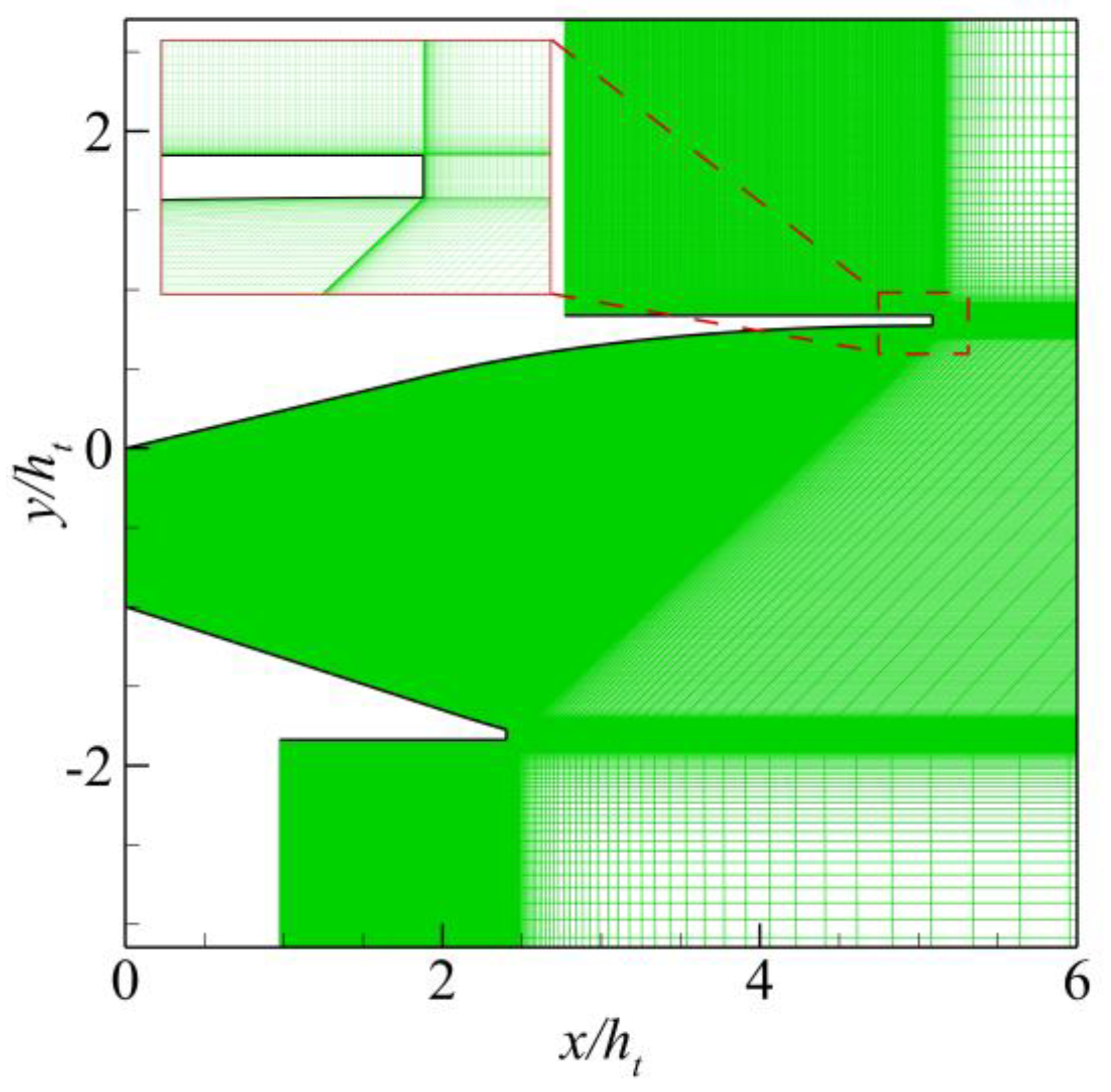
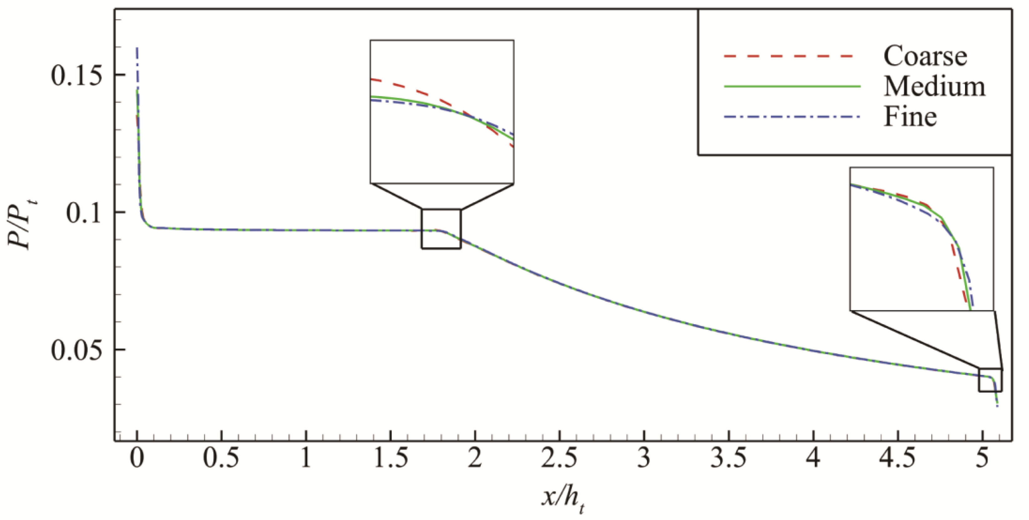
A mesh independence study is conducted to eliminate the influence of the mesh size on the results. The computational model is the nozzle designed using the proposed method in
Section 4.1, as shown in
Figure 4. The computational grids of the nozzle internal flow field with different scales are used, namely, coarse (75000 cells), medium (150000 cells), and fine (300000 cells).
Figure 5 shows the normalized pressure distribution on the ramp with different grid scales under the same working conditions. In general, the pressure distributions obtained by the three grid sizes are the same. However, the maximum relative error between the coarse grid and the fine grid is 0.25% at
x/ht≈1.8 through the amplification at
x/ht≈1.8 and 5.1. Moreover, the maximum relative error between the medium grid and the fine grid is 0.18% at
x/ht≈5.1. A medium-scale computational grid is used in the following numerical simulation work to consider the numerical accuracy and cost comprehensively.
3. Nozzle Design Methodology
3.1. Maximum Thrust Nozzle Theory Under Height Constraint
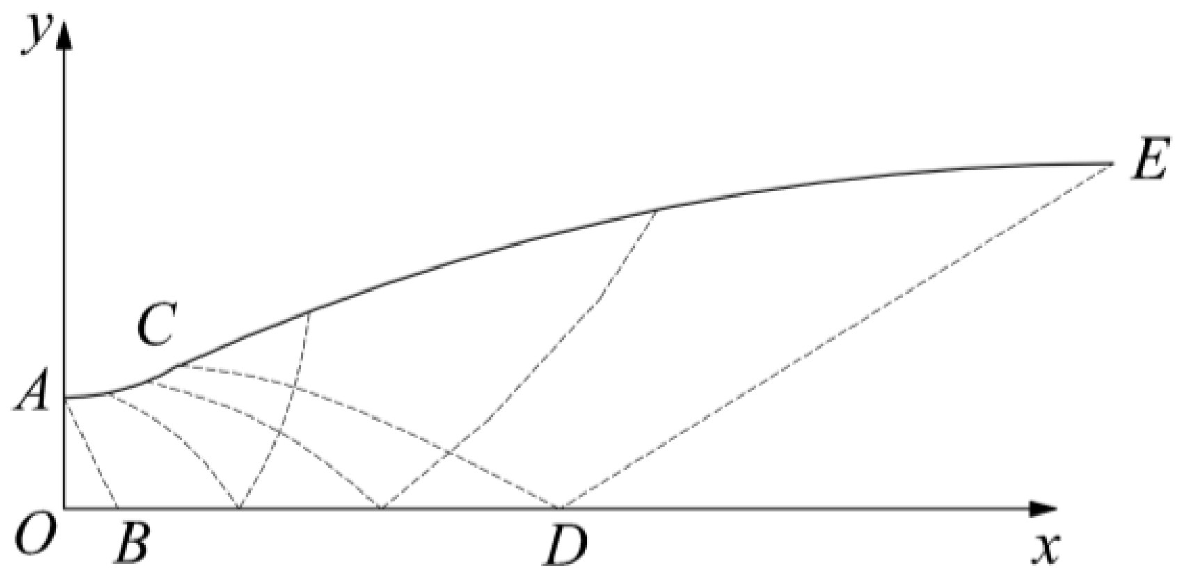
The proposed design method draws on Rao’s theory of maximum thrust nozzle and derives the optimal design conditions of the thrust nozzle under height constraints. According to the characteristic line diagram of the maximum nozzle under the height constraint given in
Figure 6, the mathematical expressions of the two constraints along the control surface
DE are as follows:
where
ρ,
θ, and
V refer to density, velocity angle, and velocity magnitude, respectively.
If
p and
pa are local static pressure and ambient back pressure, respectively, then the axial thrust
F acting on the nozzle control surface
DE is obtained as follows:
The Lagrangian multiplier method is applied to solve the maximum value of thrust
F under flow constraint ṁ and height constraint
H. This problem is equivalent to solving the unconditional maximum value of the following integral, as follows:
where
The three conditions below are obtained by solving
λ1 and
λ2, as follows:
The corner condition is satisfied by substituting (9)–(11) into (5), as follows:
Therefore, the axial thrust is maximum when the air flow direction is along the axial direction everywhere on the last characteristic line. Moreover, the aerodynamics parameters are uniformly distributed on the last characteristic line when the axial thrust is maximum.
3.2. MOC
The governing equations of the steady supersonic flow field are hyperbolic; thus, they can be solved by the MOC. The MOC is used to solve steady, 2D, planar, irrotational, supersonic flow. The characteristic line equations along the left/right running characteristic line (
C+/
C-) and their corresponding compatibility equations are as follows:
In the compatibility equation, δ = 0 is a 2D flow, and δ = 1 is an axisymmetric flow. The subscript “+” indicates the left-running characteristic line, and the subscript “−“ indicates the right-running characteristic line.
The characteristic line equation along the streamline (
C0) and its corresponding compatibility equations are as follows:
where
a is the speed of sound.
The detailed unit process of MOC can be found in [
15].
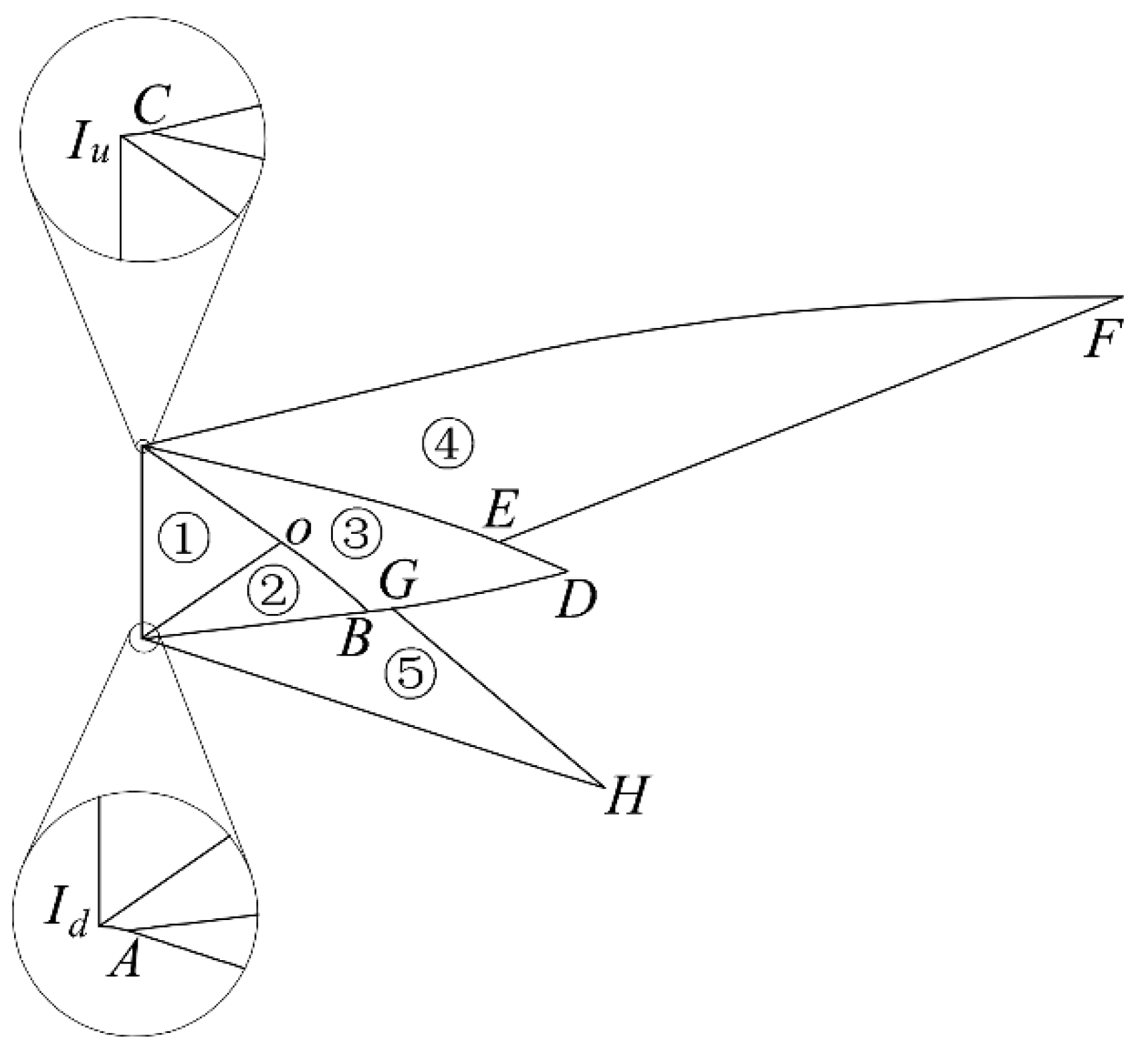
3.3. Design Process of SERN
The design process of the maximum thrust nozzle satisfying the height constraint based on the MOC is as follows:
(1) The ideal Mach number of outlet
Maideal can be obtained by (18) according to the geometry parameters of the inlet and outlet.
where
Ae,
Ain,
Main, and
κ are outlet section area, inlet section area, inlet Mach number, and heat capacity ratio.
(2) The Mach region
IuOId in
Figure 7 Schematic of MOC design procedure is calculated.
(3) The kernel region
IuCDAIdO is calculated by considering
θu and
θd. When
θu and
θd are provided, the asymmetrical factor
β can be obtained as follows:
(4) Point
E on
CDA is determined, satisfying the following two conditions:
Here, βMa is a Mach number scale factor, which is a design parameter of the proposed design method. The mechanism of βMa’s influence on the nozzle is studied subsequently.
If point E satisfying the conditions cannot be found, then θu and θd should be provided again. The kernel region IuCDAIdO is calculated until the point E that satisfies the conditions is found.
(5) According to mass flow conservation, the last characteristic line
EF of the upper turning region is derived, and the ramp profile
CF is solved.
Section 3 shows that if the nozzle has the maximum thrust under the height constraint, then the last characteristic line
EF satisfies (20) and (21) everywhere. Therefore, the aerodynamic parameters on
EF are evenly distributed.
(6) Point G on CDA is identified, and the last characteristic line GH of the lower turning region is solved according to mass flow conservation. Thus, the nozzle outlet HF can satisfy the nozzle height constraint. The aerodynamic parameters are evenly distributed on GH.
(7) The flap profile AH is calculated.
4. Parametric study of design parameters
4.1. Typical nozzle design
The design performance of the proposed nozzle can be evaluated based on an actual design case. The nozzle’s length is set to 800 mm. The flight Mach number Ma∞ is 5.
Table 1 lists the parameters of the design condition and nozzle geometric constraints required by the aircraft. The aerodynamic parameters of the nozzle inlet and the geometric constraint of the nozzle outlet height are provided. The height of the inlet and outlet of the nozzle is 157 and 400 mm, respectively. The nozzle’s length is set to 800 mm. The flight Mach number
Ma∞ is 5.
In the design program, the initial
θ1,
βMa, and
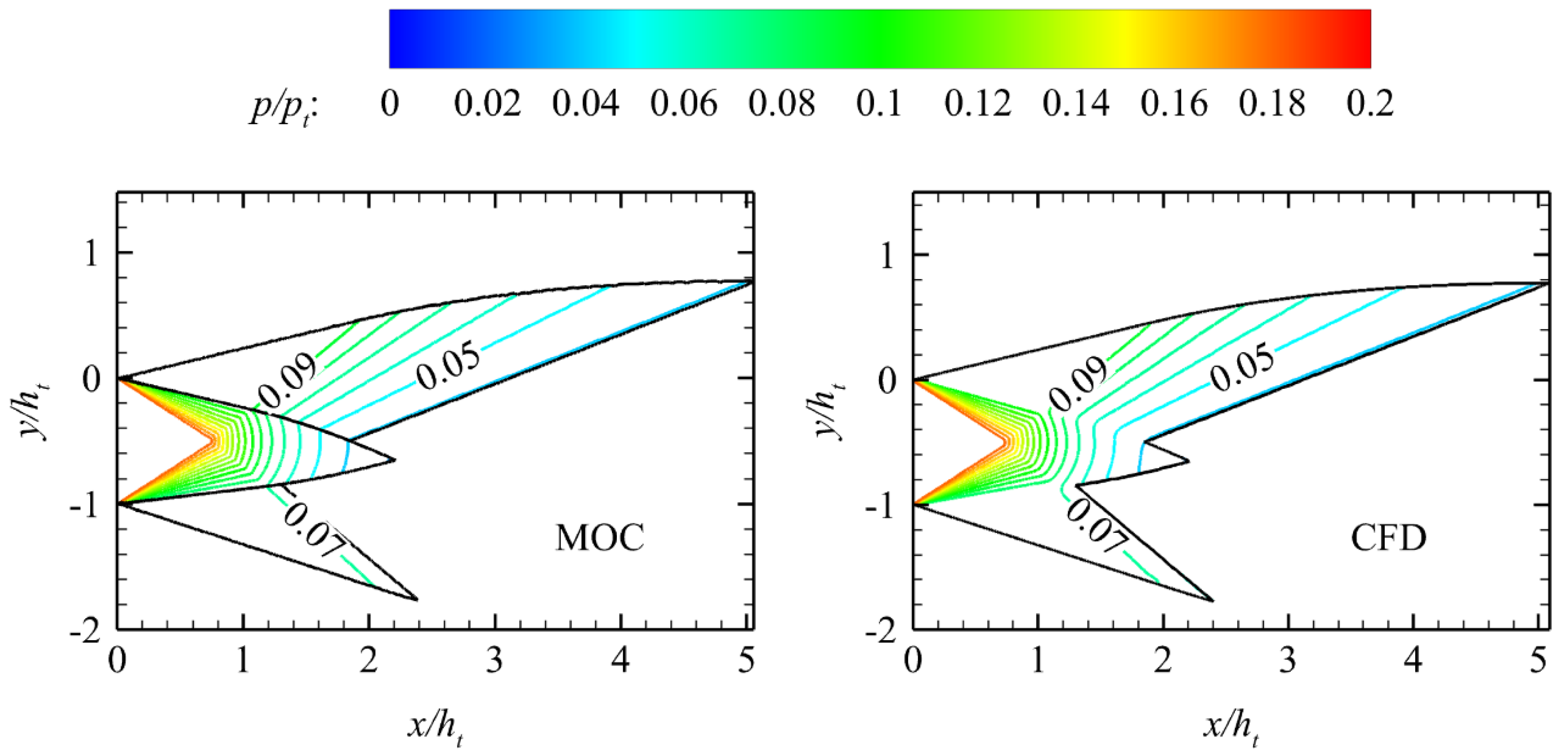
β should be provided and are set to 30°, 1, and 0.75, respectively. The comparison of the normalized pressure contour between inviscid CFD and MOC is shown in
Figure 8. The result shows the accuracy of the proposed design method.
4.2. Definition of nozzle performance parameters
The nozzle is the key component of the scramjet to generate thrust, which is an important performance parameter of the scramjet nozzle. The axial thrust and lift of the nozzle are the horizontal and vertical components of the integral of the nozzle wall pressure on the walls, respectively. The mathematical expressions are as follows:
where
pw is the wall pressure,
pa is the ambient pressure,
ṁ is mass flow rate,
Tt is the nozzle inlet total temperature,
pt is the nozzle inlet total pressure,
is the average axial velocity of the nozzle inlet,
pin is the nozzle inlet static pressure, and
R is the gas constant.
4.3. Influence of β
The asymmetrical factor
β mainly changes the shape of the kernel region
IuCDAIdO in
Figure 7 and the nozzle geometry afterward. In the design process,
θu remains constant when the inlet parameters, outlet height constraints, expansion arc radius, and
βMa remain unchanged. The value of
θd is determined when
β is fixed.
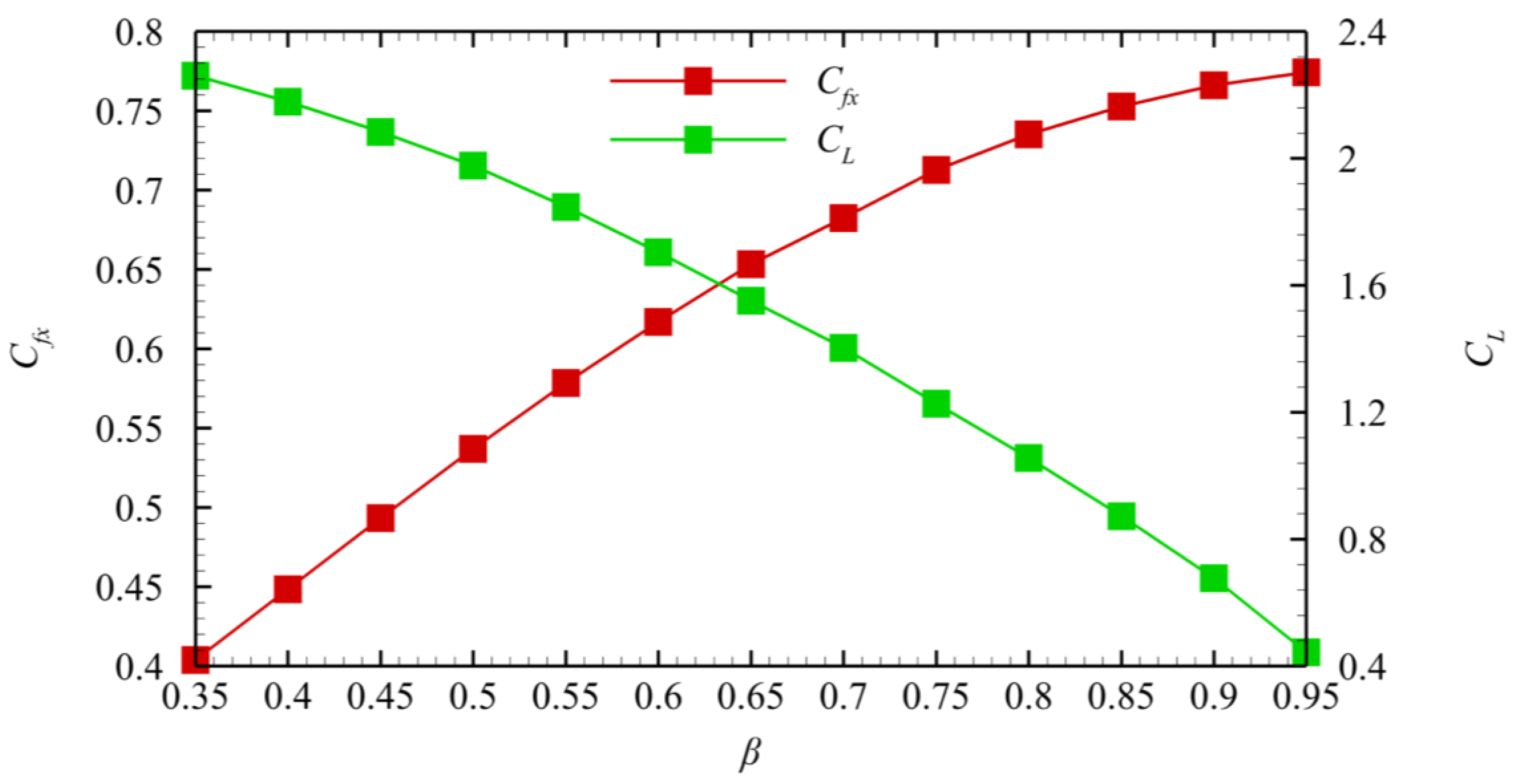
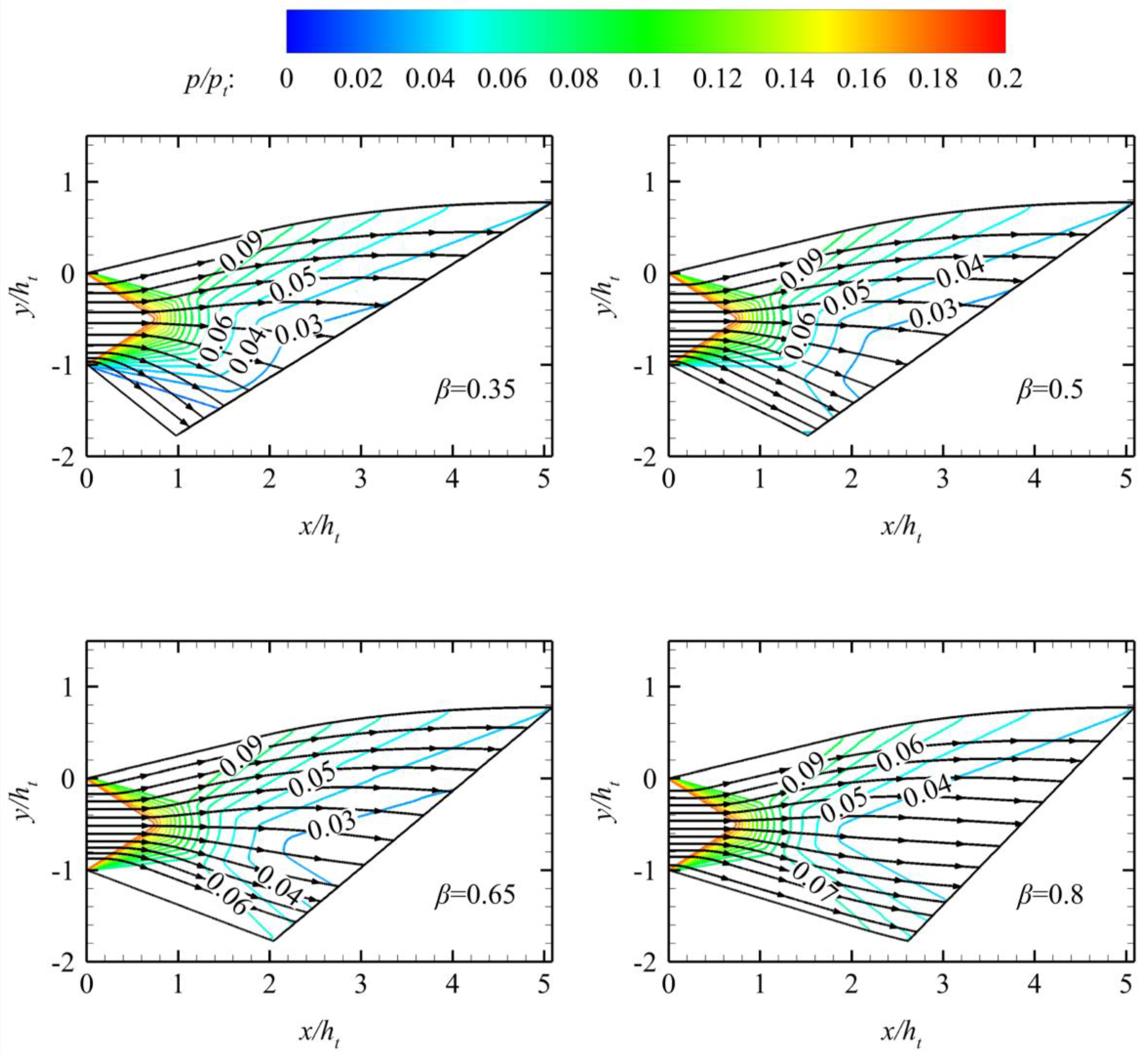
Figure 9 shows the
effect of different
β values on the axial thrust coefficient and lift of
the nozzle. In
Figure 10,
β
changes only the length of the nozzle’s flap. However, it does not change the
flap’s height and the ramp’s profile. The flap length decreases with the
decrease in
β, and the area change rate of the nozzle along the axial
direction
increases.
Thus, when
β is extremely small, the separation zone appears near the
flap because of the large
. The effectiveness
of the design method is lost due to the separation zone.
Figure 9 shows that
β is positively
correlated with the axial thrust coefficient
Cfx and
negatively correlated with the lift force.
Figure 10 shows that the streamline near the lower wall deviates from the axial
direction downward with the decrease in
β. This phenomenon results in
decreased axial momentum on the outlet, decreased axial thrust, and increased
lift.
4.4. Influence of βMa
The Mach number scale factor
βMa can control the total nozzle length under the specified height constraint. The influence of
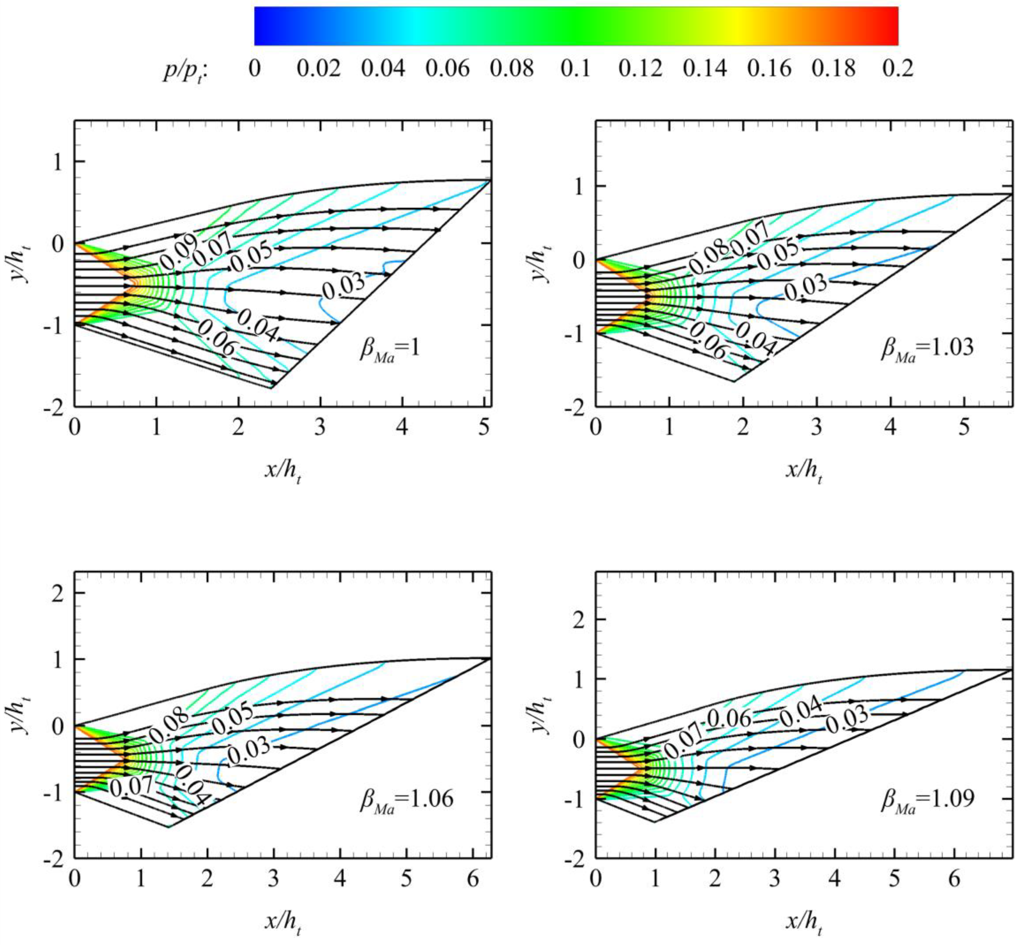
βMa on the nozzle profile is shown in
Figure 11. The figure shows that the increase in Mach number scale factor
βMa increases the ramp length while decreasing the flap length to satisfy the height constraint and
β.
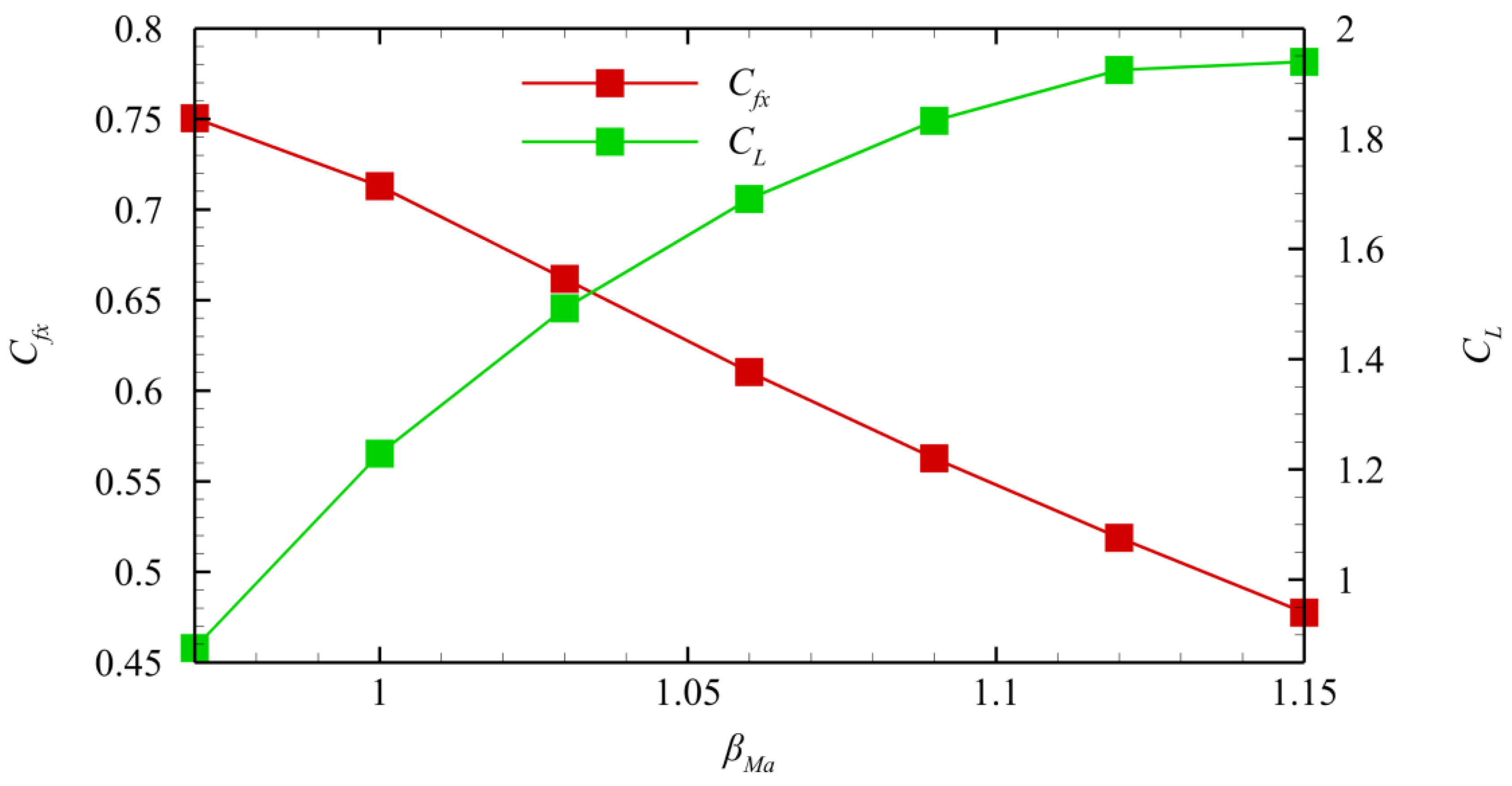
Figure 12 shows the influence of different
βMa values on the thrust coefficient and lift of the nozzle when
β = 0.75. The figure shows that the increase in
βMa increases the total length of the nozzle and decreases the length of the nozzle’s flap. Thus, the positive lift provided by the ramp increases, and the negative lift provided by the flap decreases simultaneously. The increase in nozzle geometric asymmetry increases the inhomogeneity of the aerodynamic parameters at the nozzle outlet, thereby decreasing the nozzle axial thrust coefficient. Moreover, the calculation results show that extremely large
βMa causes serious nozzle deformation, further leading to serious deterioration of nozzle performance.
The influence of
βMa in
Figure 11 on the nozzle geometry and the nozzle design process in
Figure 7 indicate that
βMa can be considered a nozzle truncation design method. When
βMa is unequal to 1, the upper wall
IuCF is designed according to
Ma = MaE instead of
Ma = Maideal. Therefore, the nozzle design flow when
βMa is larger than 1 is as follows: (1) The nozzle is designed according to the outlet Mach number
Mac in the characteristic line design program, and the area ratio of the inlet and outlet of the nozzle conforms to (18). (2) The ramp remains motionless, and the flap is truncated to satisfy the specified height constraint.
4.5. Adjusting nozzle geometry by design parameters
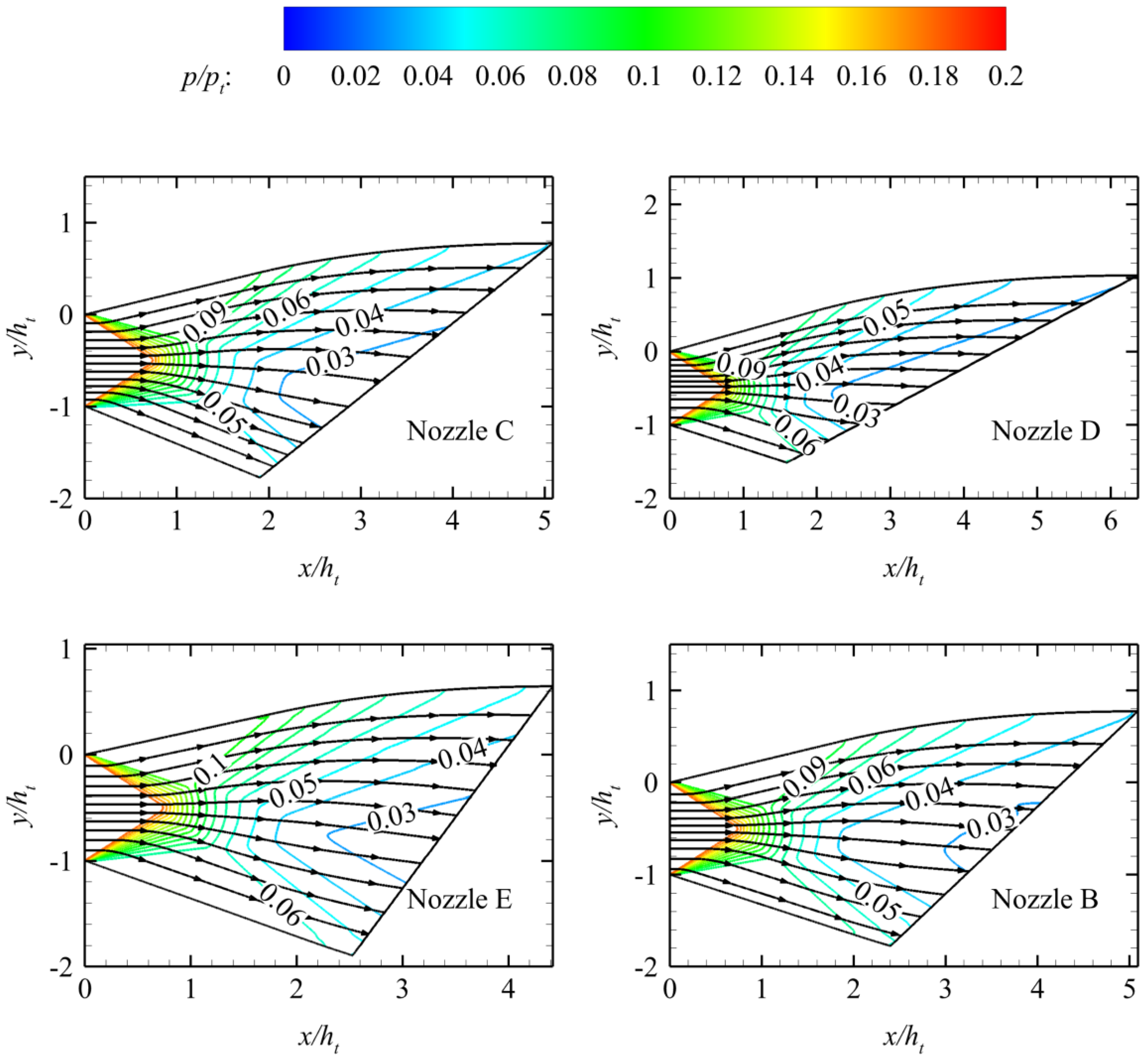
Sections 0 and 4.4 state that in the proposed design method, the lengths of the flap and the ramp can be controlled using the asymmetrical factor β and the Mach number scale factor βMa under the given height constraint. Therefore, the two design parameters can be used to adjust nozzle geometry. The influences of β and βMa on the nozzle geometry are further illustrated by three design examples.
The three sets of geometric constraints are provided by maintaining the nozzle inlet conditions and height constraints in
Section 4.1, as shown in
Table 2. The nozzle in
Section 4.1 is termed Nozzle B.
The design process is shown in
Figure 13. The design should be initially carried out according to
βMa = 1. If the total length constraint cannot be satisfied, then
βMa should be adjusted and recalculated to satisfy the total length constraint. Then,
βMa is maintained, and
β is adjusted to satisfy the constraint of the flap length.
The nozzles satisfying the geometric constraints in
Table 2 are designed using the de-sign program in
Section 3.3, and they have the same height constraint as Nozzle B. The
β and
βMa of each nozzle are shown in
Table 3, and their normalized pressure contours are shown in
Figure 14.
5. Aerodynamic performance comparisons with traditional method
5.1. Performance comparisons
The proposed design method is compared with the traditional truncation design method to prove its superiority. The typical design method is used to design the fully expanded nozzle according to the inlet and outlet conditions. Then, this nozzle is cut proportionately to satisfy the geometric constraints. The specific design steps are shown in [
16].
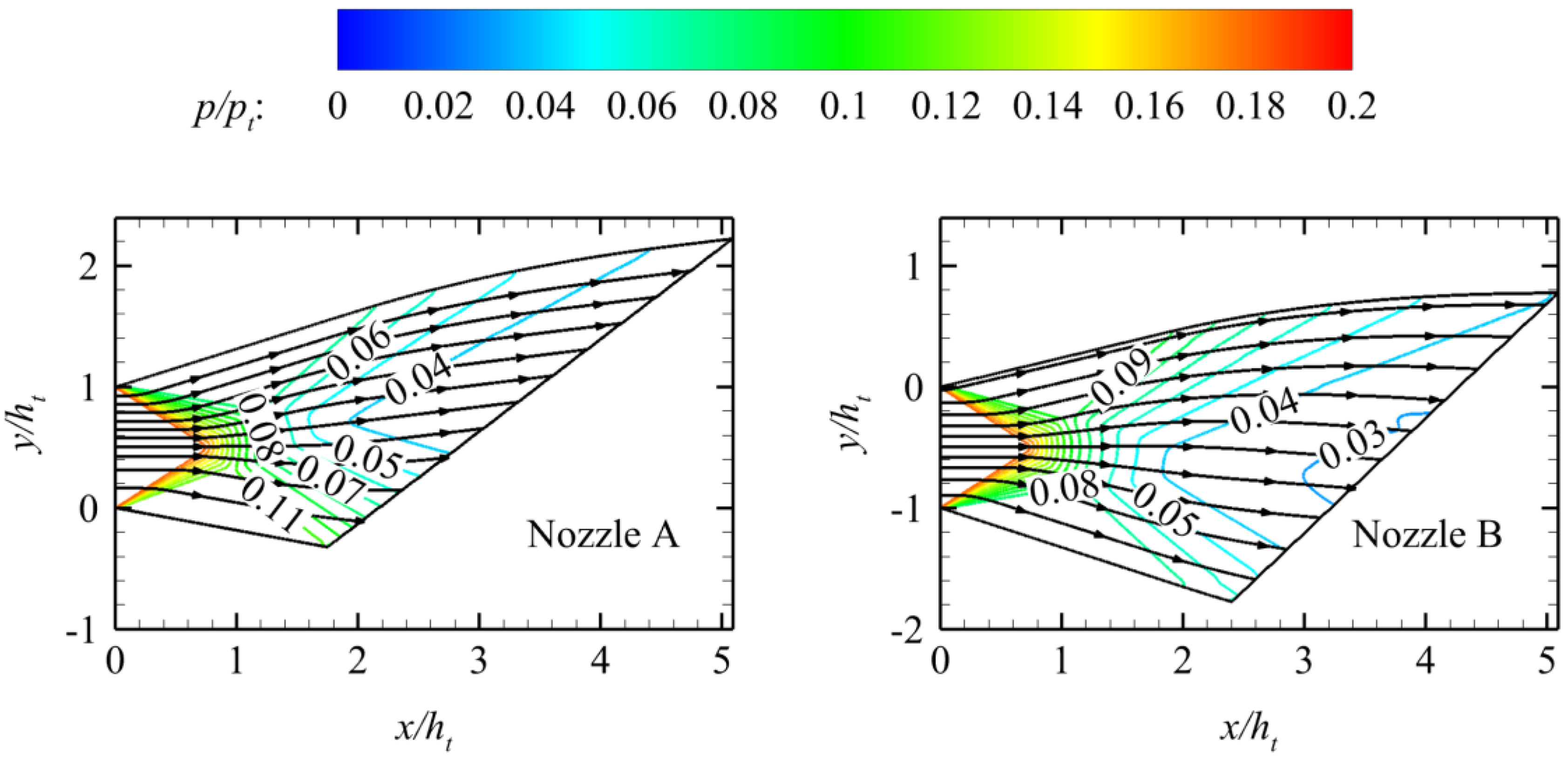
The nozzle designed by the truncation design method is referred to as Nozzle A.
Figure 15 shows that the nonuniformity of pressure distribution on the outlet of Nozzle A is greater than that of Nozzle B when the nozzle outlet height and nozzle inlet parameters are the same.
Table 4 lists the axial thrust coefficient and lift of Nozzle A and Nozzle B. The data in
Table 4 are compared. The results indicate that the thrust and lift coefficients are significantly improved. The lift of Nozzle B is larger than that of Nozzle A, probably because the velocity angle equal to zero is satisfied on the last characteristic line when the ramp profile is designed. Thus, the ramp of Nozzle B produces less negative lift than that of Nozzle A.
5.2. Off-design Performance
The nozzle should provide sufficient thrust when the vehicle gains altitude and takes off horizontally. Thus, the aerodynamic performance under off-design operating points should be studied. The aerodynamic performances under the off-design operating points of Nozzle A and Nozzle B are compared to reflect the superiority of the proposed design method. Some typical off-design operating points are selected, as shown in
Table 5. When NPR is 25.35, the nozzle is under the equal expansion condition at the inlet and outlet sizes according to (18), and NPR is 69.22 at the design point.
In
Table 5, operating points
Ma∞ = 2.5 and
Ma∞ = 3 are in the overexpansion state. The operating points
Ma∞ = 3.5 and
Ma∞ = 4 are in the state of under expansion. However, the NPR is less than that at the design point. In addition, the transition point of the combined cycle engine’s working mode is usually near
Ma∞ = 2.5 in actual flight; thus, the typical off-design working conditions in
Table 5 reflect the working performance of the nozzle in the full flight envelope under the ramjet mode.
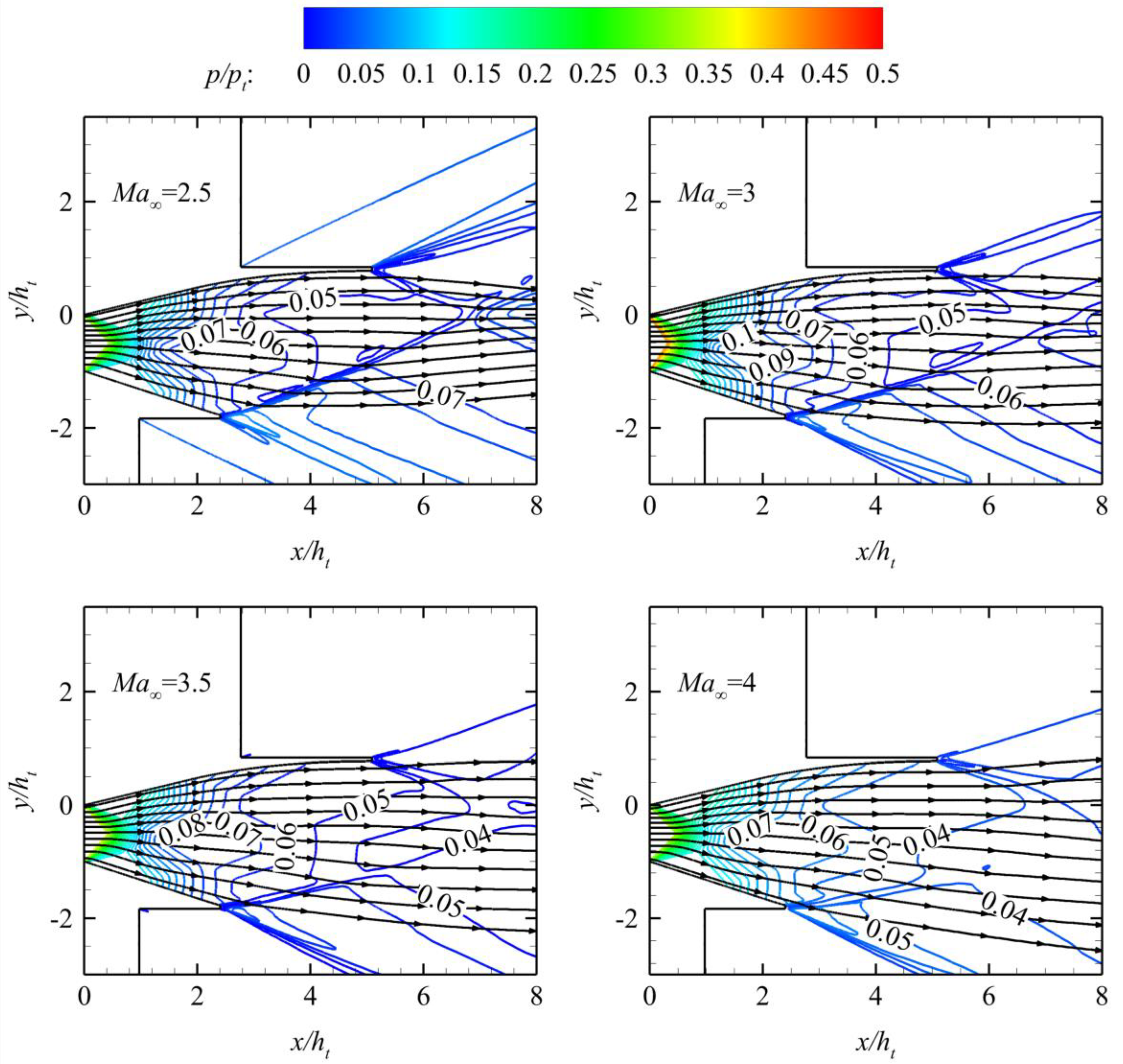
Figure 16 shows the normalized pressure contours under various typical off-design conditions in
Table 5.
Table 6 shows the thrust and lift coefficient under various off-design conditions. The aerodynamics performance of Nozzle A under various off-design conditions in
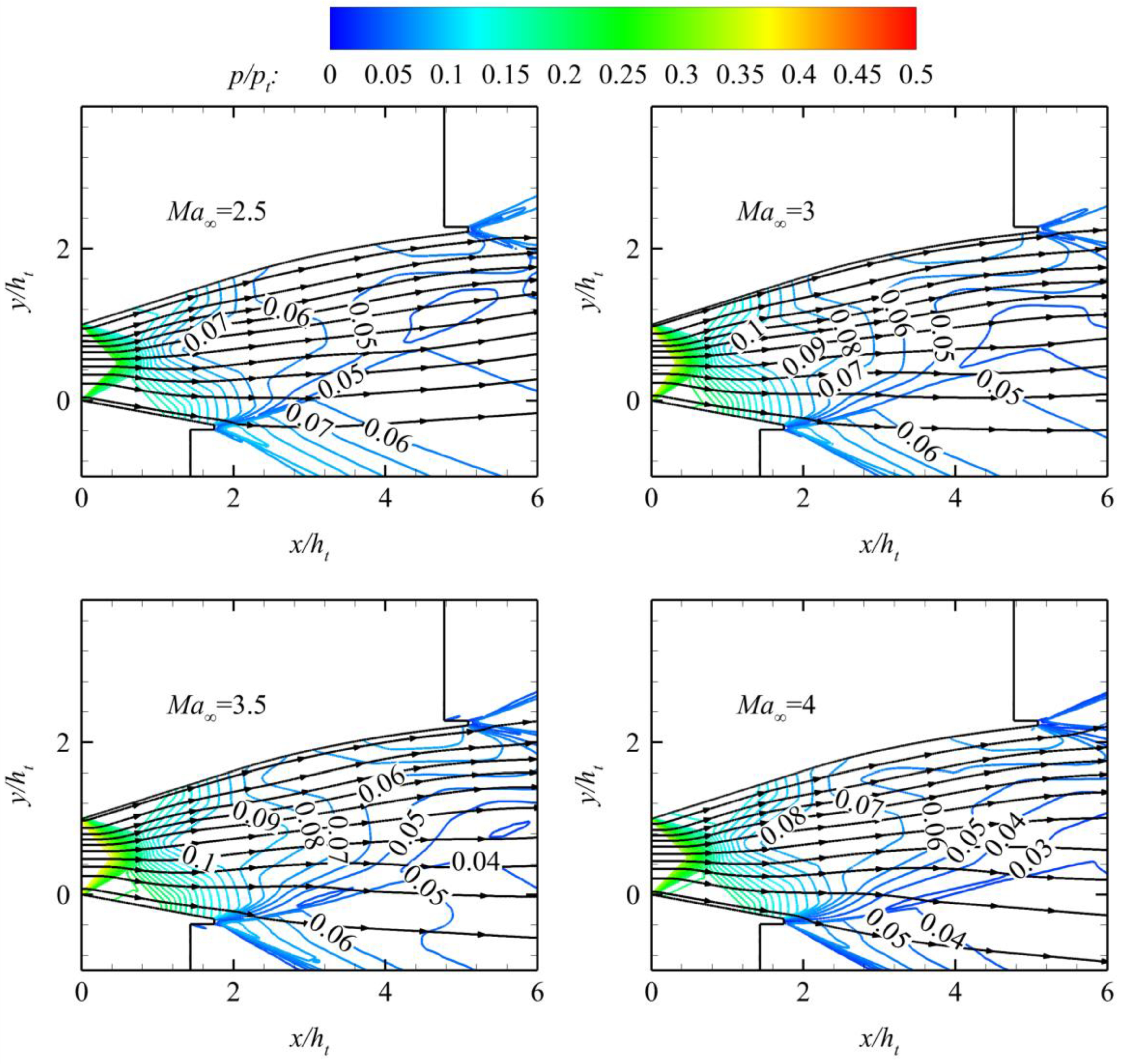
Table 5 is also calculated. The normalized pressure contours are shown in
Figure 17, and the thrust and lift coefficients are shown in
Table 7.
Figure 16 shows that the increase in NPR weakens the intensity of the oblique shock wave at the nozzle outlet, increases the downward angle of the streamline near the flap outlet, and makes the streamline near the outlet of the ramp relatively close to the horizontal direction. The change trend of the streamline near the flap in
Figure 17 is the same as that in
Figure 16. However, the streamline near the ramp is always upward. The positive lift generated by Nozzle B is larger than that by Nozzle A under the same working conditions because of the difference in the streamline on the ramp between Nozzle A and Nozzle B. After the thrust data comparison, the thrust coefficient of Nozzle B is slightly larger than that of Nozzle A. This finding proves that the aerodynamic performance of the nozzle by the proposed design method is better than that by the traditional proportional truncation method under off-design conditions.
6. Conclusion
In this study, the height constraint is directly introduced into the maximum thrust nozzle theory, and the maximum thrust nozzle satisfying the height constraint is designed using MOC. In this design method, the nozzle’s ramp and flap lengths are controlled by adjusting the asymmetrical factor β and the Mach number scale factor βMa under the specified outlet height constraint. The main conclusions are as follows:
1. βMa mainly controls the total length of the nozzle. The total length of the nozzle increases with the increase in βMa. The flap length decreases, and the positive lift of the nozzle increases to satisfy the height constraint. The increase in βMa increases the geometric asymmetry of the nozzle while decreasing Cfx and increasing CL. In the actual design, extremely large βMa leads to a rapid deterioration of nozzle performance when β and the height constraint remain.
2. The influence of β on nozzle geometry is that only the flap length changes when the ramp profile and the flap height are unchanged. The flap length increases with the increase in β. Moreover, the streamline near the flap becomes close to the axial direction, thereby increasing the thrust coefficient and decreasing the lift. In the actual design, the nozzle is designed under the specified geometric constraints by adjusting βMa and β.
3. Compared with those of the nozzle (Nozzle A) designed using the traditional truncated design method, the thrust and lift coefficients of the nozzle (Nozzle B) designed using the proposed method are increased by 11.93% and 138.45%, respectively, at the design point. At the same off-design point, the thrust and lift coefficients of Nozzle B are greater than those of Nozzle A. Compared with the thrust coefficient of Nozzle A, that of Nozzle B is increased by 8.79% at most under various typical off-design working conditions. Moreover, the positive lift force is maintained in the entire working condition range.
Author Contributions
Conceptualization, Xu J. L. and Yu K. K.; formal analysis, Yu K. K. and Huang B. W.; software, Yu K. K. and Huang B. W.; projection administration, Xu J. L. and Yu K. K.; methodology, Huang B. W.; supervision, Xu J. L. All authors have read and agreed to the published version of the manuscript.
Data Availability Statement
Data sharing not applicable.
Acknowledgments
We would like to acknowledge the continued support of Postgraduate Research & Practice Innovation Program of NUAA, grant number xcxjh20220204.
Conflicts of Interest
The authors declare no conflict of interest.
Nomenclature
| A |
= |
area |
| a |
= |
speed of sound |
| Cfx |
= |
axial thrust coefficient |
| CL |
= |
lift coefficient |
| e |
= |
total energy |
| F |
= |
force |
| H |
= |
height |
| κ |
= |
heat capacity ratio |
| L |
= |
length |
| Ma |
= |
Mach number |
| ṁ |
= |
mass flow rate |
| p |
= |
pressure |
| Q |
= |
rate of volumetric heat addition per unit mass |
| R |
= |
gas constant |
| T |
= |
temperature |
| V |
= |
velocity |
| x |
= |
x direction coordinate |
| y |
= |
y direction coordinate |
| δ |
= |
axial/2D switch |
| φ |
= |
slope angle |
| ρ |
= |
density |
| θ |
= |
velocity angle |
| τ |
= |
shearing stress |
| Subscript |
| a |
= |
atmosphere |
| e |
= |
nozzle exit |
| w |
= |
wall |
| t |
= |
total |
| in |
= |
nozzle entrance |
| ∞ |
= |
free stream |
References
- Zhiyong, L. , A REVIEW ON HYPERSONIC AIRBREATHING PROPULSION SYSTEM." Advances in Mechanics 2009.
- Wu, Y. , et al. Progress in airframe-propulsion integration technology of air-breathing hypersonic vehicle. Acta Aeronautica Et Astronautica Sinica 2015, 36.1:245-260.
- Jin Jie, Chen Min, Liu Yuying, et al. Turbine Based Combined Cycle Engine.; National Defense Industry Press: Beijing, China, 2019; pp. 154–196.
- Chen Yile, Yu Kaikai, Xu Jinglei. New design method for scramjet nozzles with strong geometric constraints. Acta Aeronautica et Astronautica Sinica 2021, 42,12459. [CrossRef]
- RAO G V R. Exhaust nozzle contour for optimum thrust. Jet Propulsion 1958. 28, 377–382. [CrossRef]
- LU X, YUE L, XIAO Y, et al. Design of Scramjet Nozzle Employing Streamline Tracing Technique, 16th AIAA/DLR/DGLR International Space Planes and Hypersonic Systems and Technologies Conference. 2009. [CrossRef]
- LV Z, XU J L, YU Y, et al. A new design method of single expansion ramp nozzles under geometric constraints for scramjets. Aerospace Science and Technology 2017, 66, 129-139. [CrossRef]
- Yu K K, Chen Y L, Huang S, et al. Inverse Design Method on Scramjet Nozzles Based on Maximum Thrust Theory. Acta Astronautica 2020, 166, 162-171. [CrossRef]
- YU Kaikai, CHEN Yile, HUANG Shuai, XU Jinglei. Inverse Design Method on Scramjet Nozzle with Full Geometrical Constraints for Nozzle-Afterbody Integration. Journal of Aerospace Engineering 2021, 34, 04021004. [CrossRef]
- Chen K, Xu J, Qin Q, Xiong W, et al. Design of Thrust-Optimized Scramj-et Nozzle and Its Concise Estimation Method. AIAA Journal 2021, 59, 2014–2026. [CrossRef]
- ARGROWB M. Comparison of minimum length nozzles. Journal of Fluids Engineering 1988, 110, 283. [CrossRef]
- Shyne R J , Keith T G J .Analysis and design of optimized truncated scarfed nozzles subject to external flow effects. aiaa journal 1990. [CrossRef]
- Hoffman J D .Design of compressed truncated perfect nozzles. Aiaa Paper 2015, 3:150-156. [CrossRef]
- Bare E A , Capone F J .Static Internal Performance of Convergent Single-Expansion-Ramp Nozzles With Various Combinations of Internal Geometric Parameters. 1989.
- Zucrow M J, Hoffman J D. Gas dynamics. vol. 2-Multidimensional Flow. New York, 1977.
- MO Jianwei, XU Jinglei, QUAN Zhibin, YU Kaikai, LV Zheng. Design and cold flow test of a scramjet nozzle with nonuniform inflow. Acta Astronautica 2014, 108, 92-105. [CrossRef]
Figure 1.
Sketch of the GR3 SERN.
Figure 1.
Sketch of the GR3 SERN.
Figure 2.
Computational grid of SERN.
Figure 2.
Computational grid of SERN.
Figure 3.
Comparison between CFD and Experiment.
Figure 3.
Comparison between CFD and Experiment.
Figure 4.
Computational grid of the model.
Figure 4.
Computational grid of the model.
Figure 5.
Influence of different grid numbers on normalized pressure distribution on the ramp of nozzle3.
Figure 5.
Influence of different grid numbers on normalized pressure distribution on the ramp of nozzle3.
Figure 6.
Schematic of characteristic lines of maximum nozzle under height constraint.
Figure 6.
Schematic of characteristic lines of maximum nozzle under height constraint.
Figure 7.
Schematic of MOC design procedure.
Figure 7.
Schematic of MOC design procedure.
Figure 8.
Pressure contours of nozzle by MOC and CFD.
Figure 8.
Pressure contours of nozzle by MOC and CFD.
Figure 9.
Thrust coefficient and lift coefficient of nozzle with different β values.
Figure 9.
Thrust coefficient and lift coefficient of nozzle with different β values.
Figure 10.
Pressure contours of nozzles with different β values.
Figure 10.
Pressure contours of nozzles with different β values.
Figure 11.
Pressure contours of nozzles with different βMa values.
Figure 11.
Pressure contours of nozzles with different βMa values.
Figure 12.
Thrust coefficient and lift coefficient of nozzle with different βMa values.
Figure 12.
Thrust coefficient and lift coefficient of nozzle with different βMa values.
Figure 13.
Design process under full geometric constraints.
Figure 13.
Design process under full geometric constraints.
Figure 14.
Pressure contours of different geometric constraints.
Figure 14.
Pressure contours of different geometric constraints.
Figure 15.
Comparison of pressure contours under different design methods.
Figure 15.
Comparison of pressure contours under different design methods.
Figure 16.
Normalized pressure contours of Nozzle B in different typical off-design working points.
Figure 16.
Normalized pressure contours of Nozzle B in different typical off-design working points.
Figure 17.
Normalized pressure contours of Nozzle A in different typical off-design working points.
Figure 17.
Normalized pressure contours of Nozzle A in different typical off-design working points.
Table 1.
Parameters of the design condition and nozzle geometric constraints.
Table 1.
Parameters of the design condition and nozzle geometric constraints.
| Main
|
pin (Pa) |
Tin (K) |
H (km) |
Hin (mm) |
He (mm) |
L (mm) |
Ma∞
|
| 1.76 |
45455 |
1822 |
23 |
157 |
400 |
800 |
5 |
Table 2.
Different geometric constraints of nozzle.
Table 2.
Different geometric constraints of nozzle.
| |
Flap Length (m) |
Ramp Length (m) |
| Nozzle C |
0.8 |
0.3 |
| Nozzle D |
1 |
0.25 |
| Nozzle E |
0.7 |
0.4 |
Table 3.
Design parameters of different geometric constraints.
Table 3.
Design parameters of different geometric constraints.
| |
βMa |
β |
| Nozzle C |
1 |
0.61 |
| Nozzle D |
1.064 |
0.87 |
| Nozzle E |
0.963 |
0.625 |
Table 4.
Thrust coefficient and lift coefficient under different design methods.
Table 4.
Thrust coefficient and lift coefficient under different design methods.
| |
Cfx |
CL |
| Nozzle A |
0.675 |
0.483 |
| Nozzle B |
0.713 |
1.228 |
Table 5.
Parameters of typical off-design conditions.
Table 5.
Parameters of typical off-design conditions.
| Ma∞
|
pa (Pa) |
pt (Pa) |
Tt (K) |
Main
|
|
2.5
|
11554.39 |
131300 |
1500 |
1.37 |
|
3
|
8054.66 |
133000 |
1871 |
1.19 |
|
3.5
|
5886.79 |
160000 |
2203 |
1.3 |
|
4
|
4515.753 |
210000 |
2409 |
1.4 |
Table 6.
Cfx and CL of Nozzle B in different typical off-design working points.
Table 6.
Cfx and CL of Nozzle B in different typical off-design working points.
| Ma∞
|
Cfx
|
CL
|
|
2.5
|
0.668 |
0.009 |
|
3
|
0.867 |
0.689 |
|
3.5
|
0.839 |
0.870 |
|
4
|
0.766 |
0.920 |
Table 7.
Cfx and CL of Nozzle A in different typical off-design working points.
Table 7.
Cfx and CL of Nozzle A in different typical off-design working points.
| Ma∞
|
Cfx
|
CL
|
| 2.5 |
0.614 |
−1.761 |
| 3 |
0.861 |
−0.063 |
| 3.5 |
0.820 |
0.314 |
| 4 |
0.740 |
0.438 |
|
Disclaimer/Publisher’s Note: The statements, opinions and data contained in all publications are solely those of the individual author(s) and contributor(s) and not of MDPI and/or the editor(s). MDPI and/or the editor(s) disclaim responsibility for any injury to people or property resulting from any ideas, methods, instructions or products referred to in the content. |
© 2023 by the authors. Licensee MDPI, Basel, Switzerland. This article is an open access article distributed under the terms and conditions of the Creative Commons Attribution (CC BY) license (http://creativecommons.org/licenses/by/4.0/).
