Submitted:
05 October 2023
Posted:
06 October 2023
You are already at the latest version
Abstract
Keywords:
1. Introduction
2. Device Models for Simulation
2.1. Poisson’s Equation
2.2. Continuity Equation
2.3. Charge Transport Model
2.4. Photons Absorption Model
3. Simulation Software
4. Simulation Steps:
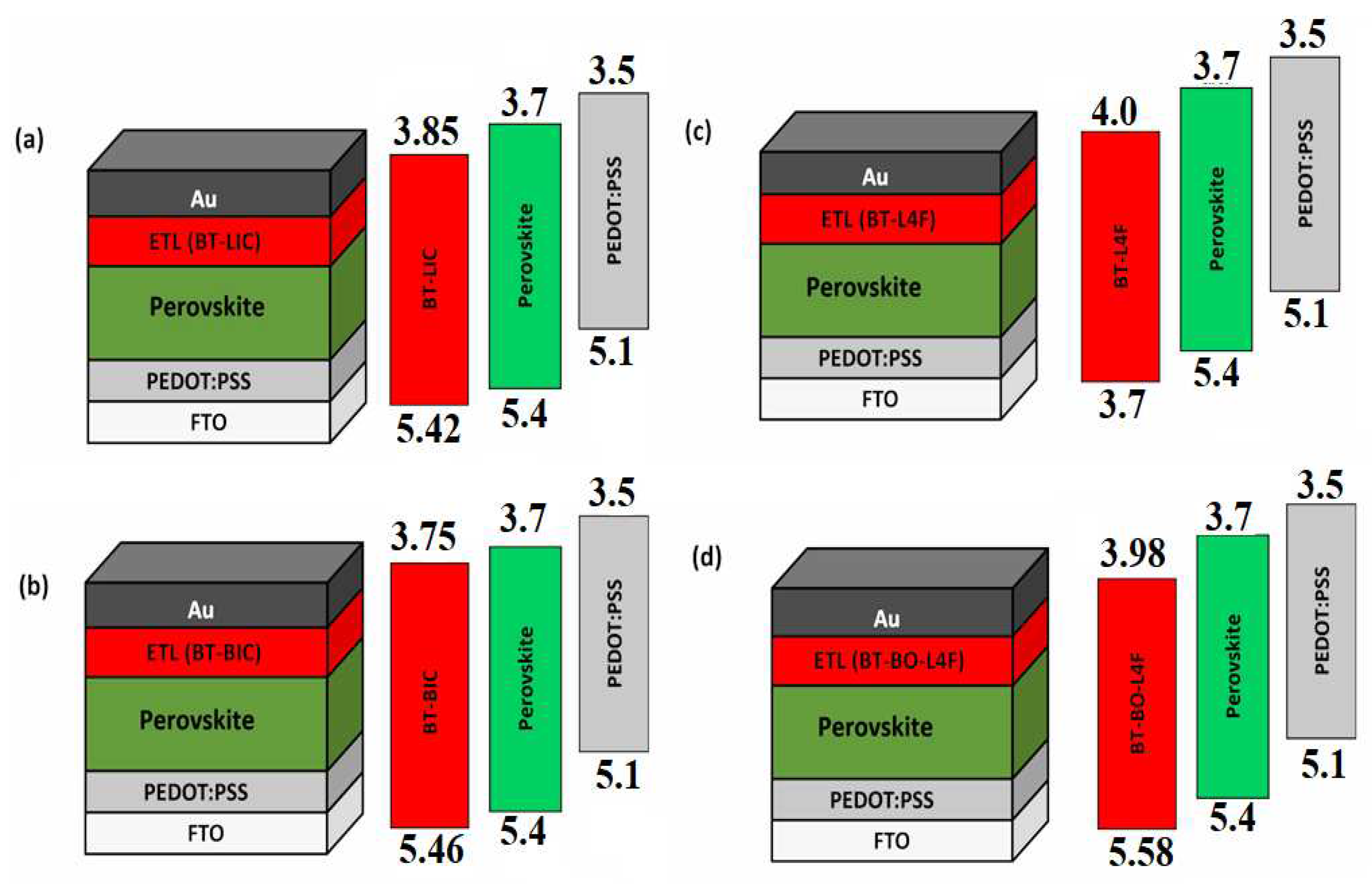
- Step 1, Start of Simulation: Define the environment, geometry, and physical parameters of all the device’s layers.
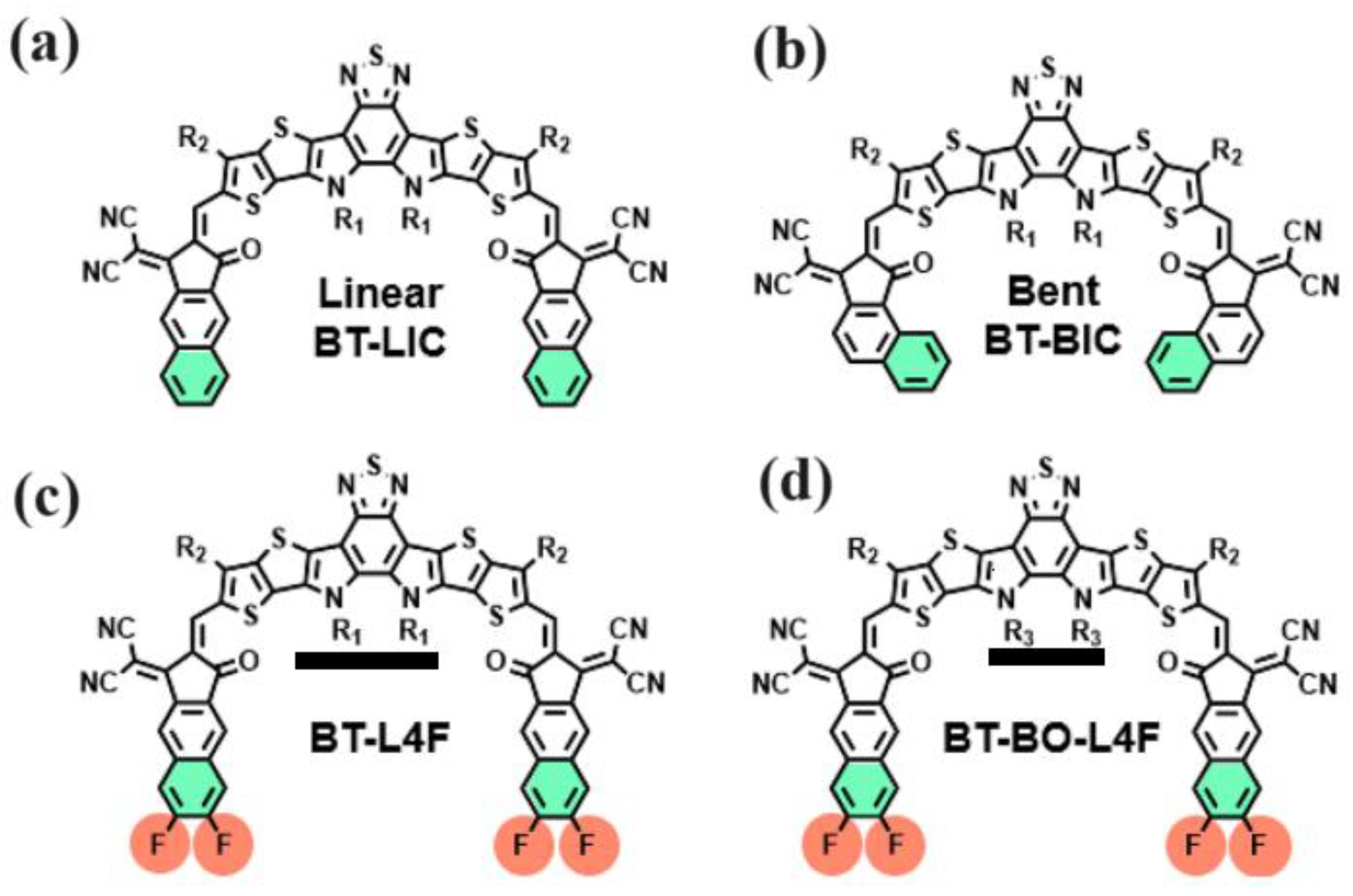
- Step 3, Estimation of Ranges for Different Parameters: Propose the range of thickness and doping density for each layer of the devices (i) Device BT-LIC, (ii) Device BT-BIC, (iii) Device BT-L4F, and (iv) Device BT-BO-L4F from the literature.
- Step 4, Thickness Optimization of HTL: Determine the optimal thickness of PEDOT:PSS for each device as a hole transport layer through a series of simulations, which gives the maximum power-conversion efficiency and quantum efficiency (QE). After that, update with the optimal thickness of PEDOT:PSS for further simulations.
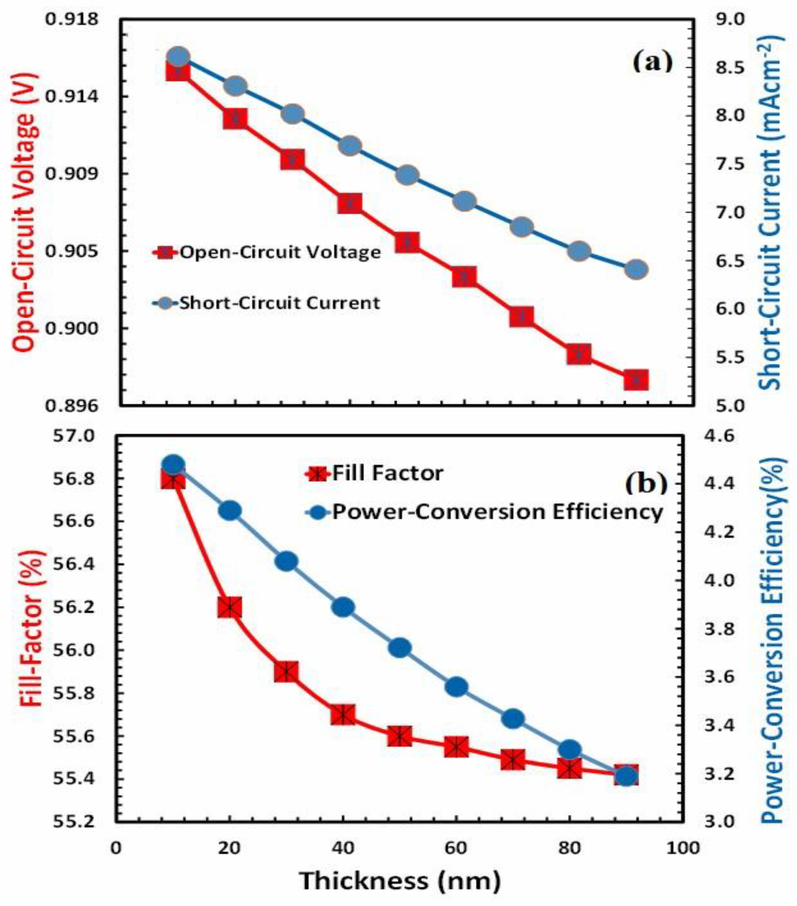
- Step 5, Determination of PV Parameters as a Function of HTL Thickness: Determine the photovoltaic parameters such as open-circuit voltage, short-circuit current, fill factor, and power conversion efficiency of each device as a function of PEDOT:PSS thickness. But for simplicity, only the photovoltaic parameters of a highly efficient device are shown and discussed.
- Step 6, Thickness Optimization of ETL: Determine the optimal thickness of ETL ( (i) BT-LIC, (ii) BT-BIC, (iii) BT-L4F, and (iv) BT-BO-L4F) for each device as an electron transport layer through a series of simulations, which gives the maximum power-conversion efficiency and quantum efficiency. After that, update with the optimal thickness of ETL for further simulations.
- Step 7, Determination of PV Parameters as a Function of Optimized ETL Thickness: Determine the photovoltaic parameters such as open-circuit voltage, short-circuit current, fill factor, and power conversion efficiency of each device as a function of electron-transfer layer thickness. But for simplicity, only the photovoltaic parameters of a highly efficient device are shown and discussed.
- Step 8, Thickness Optimization of Perovskite Absorber Layer: Determine the optimal thickness of the perovskite absorber layer Cs2AgBi0.75Sb0.25Br6) for each device as an absorber layer through a series of simulations, which gives the maximum power-conversion efficiency and quantum efficiency. Then, update with the optimal thickness of the absorber for further simulations.
- Step 9, Determination of PV Parameters as a Function of Perovskite Thickness: Determine the photovoltaic parameters such as open-circuit voltage, short-circuit current, fill factor, and power conversion efficiency of each device as a function of absorber thickness. But for simplicity, only the photovoltaic parameters of a highly efficient device are shown and discussed.
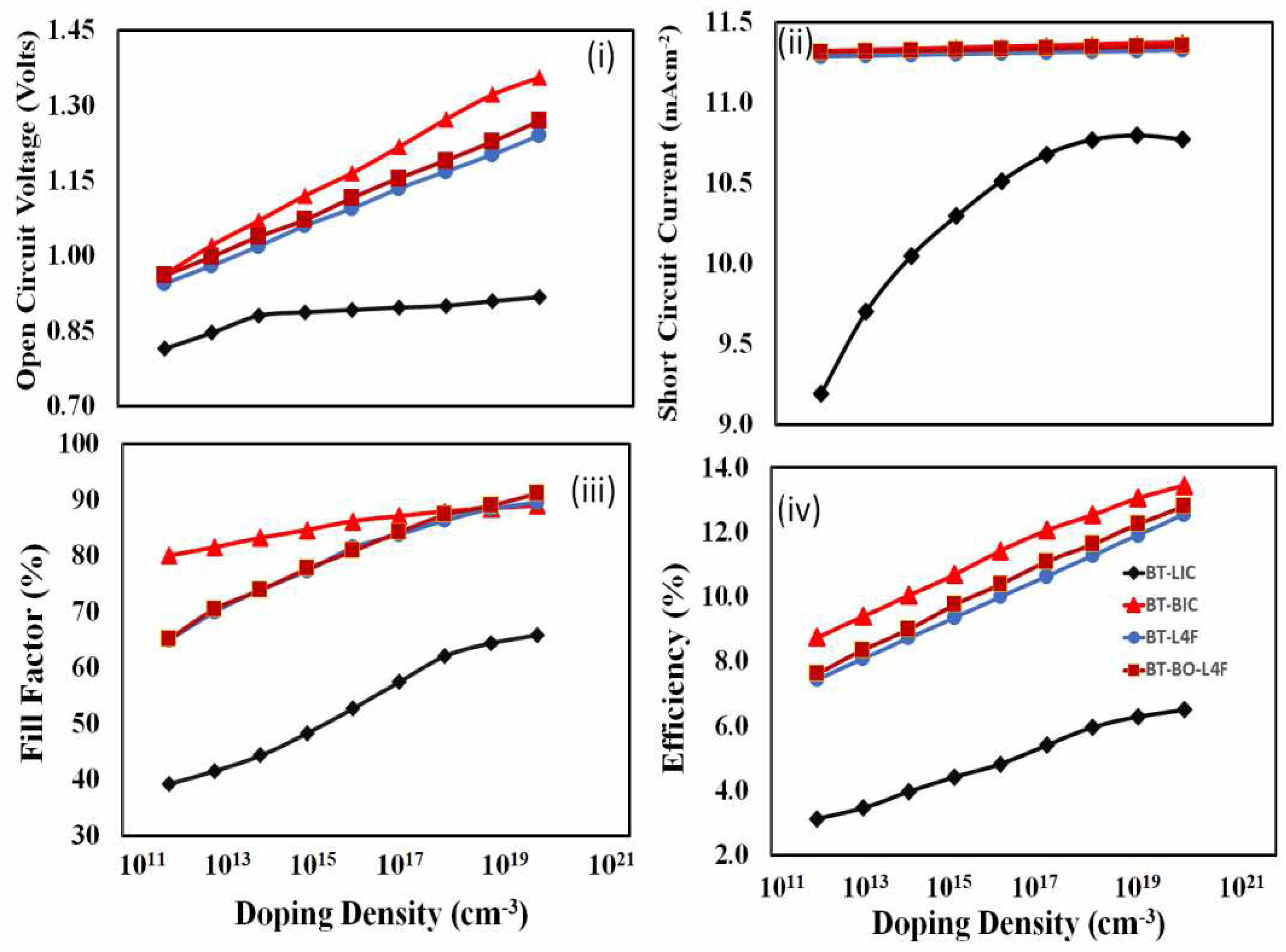
- Step 10, Determination of PV parameters as a function of ETL Doping: Determine the photovoltaic parameters such as open-circuit voltage, short-circuit current, fill factor, and power conversion efficiency of each device as a function of ETL doping density.
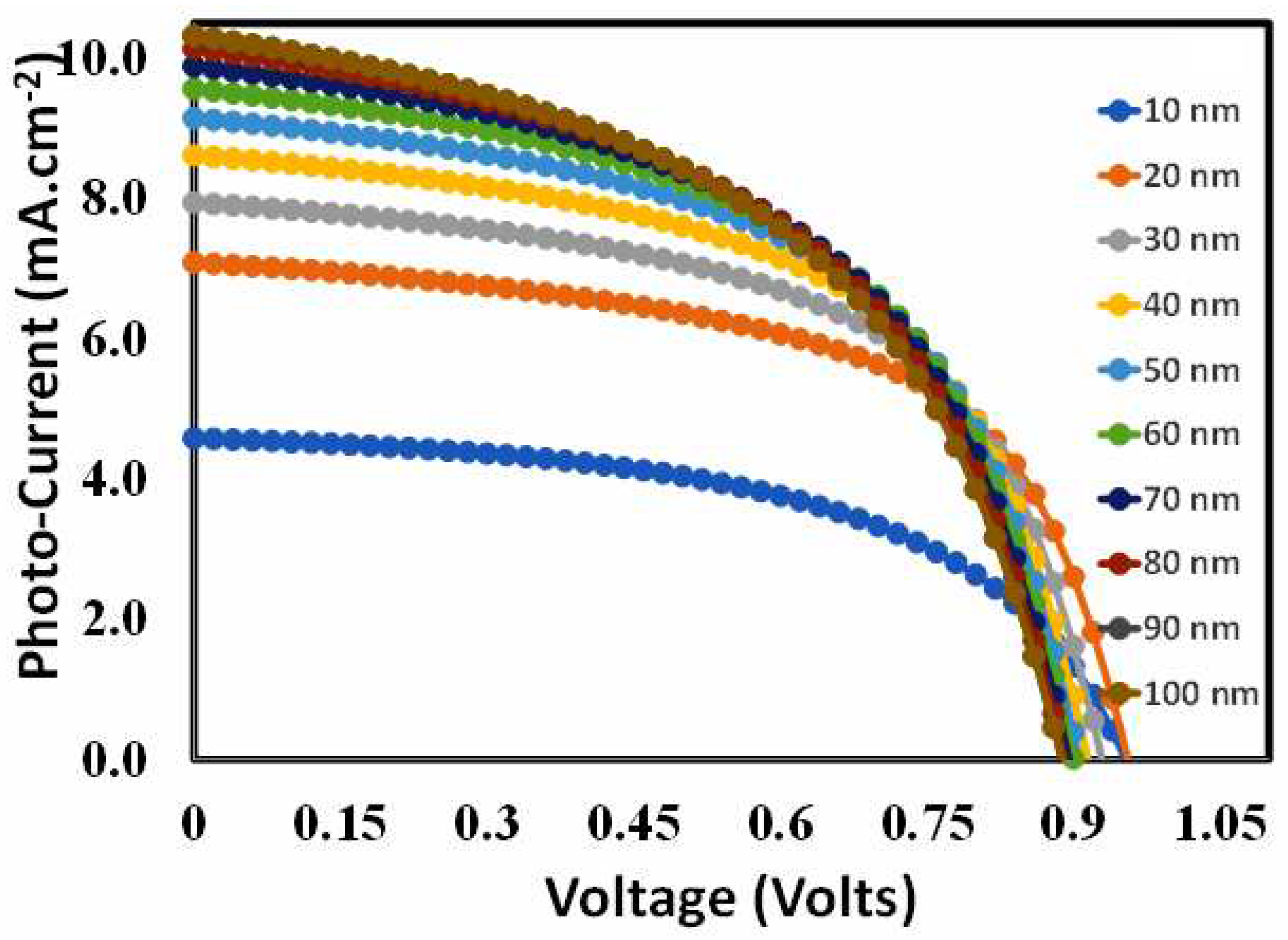
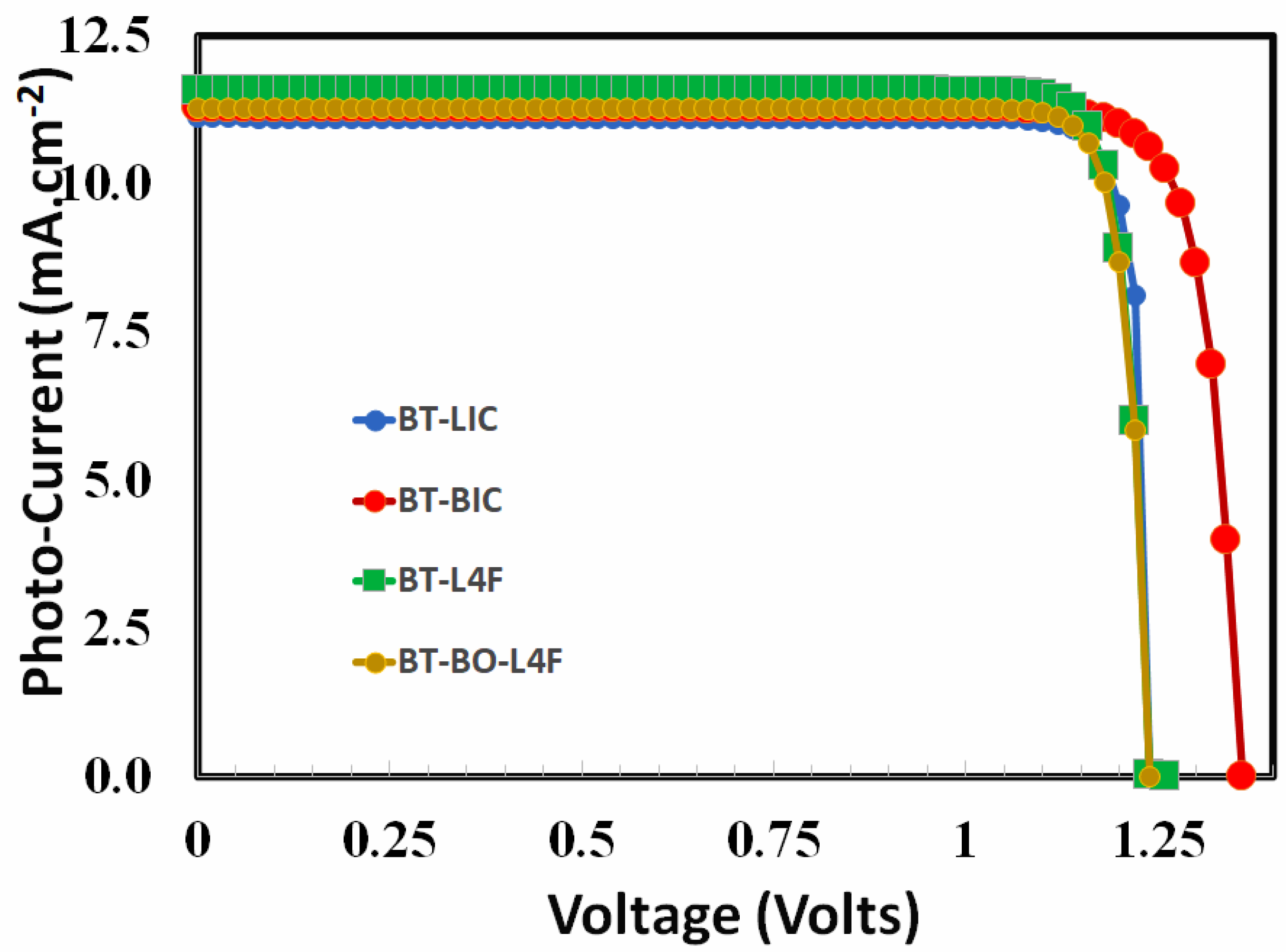
- Step 11, Determination of PV Response and Parameters of the Optimized Devices: Determine the photovoltaic current-voltage response and other photovoltaic parameters of all the optimized devices. such as open-circuit voltage, short-circuit current, fill factor, and power conversion efficiency of each device as a function of ETL doping density.
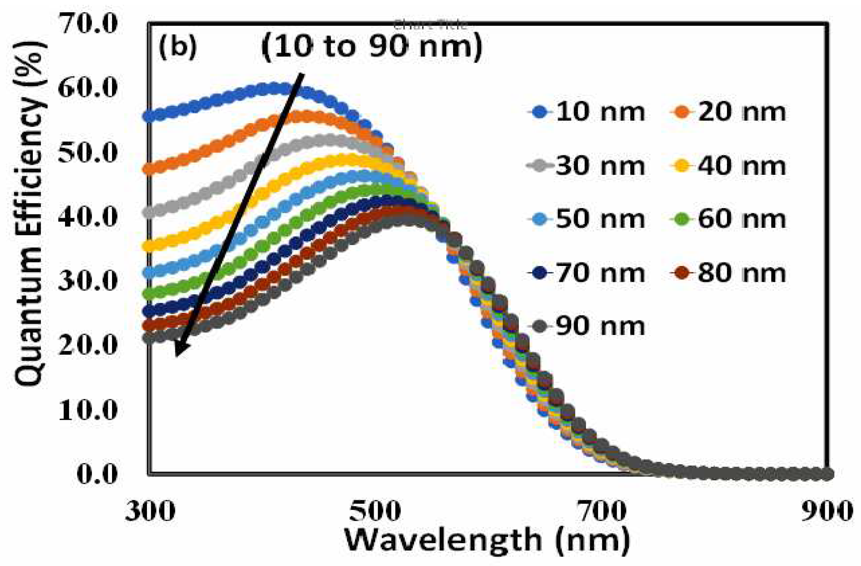
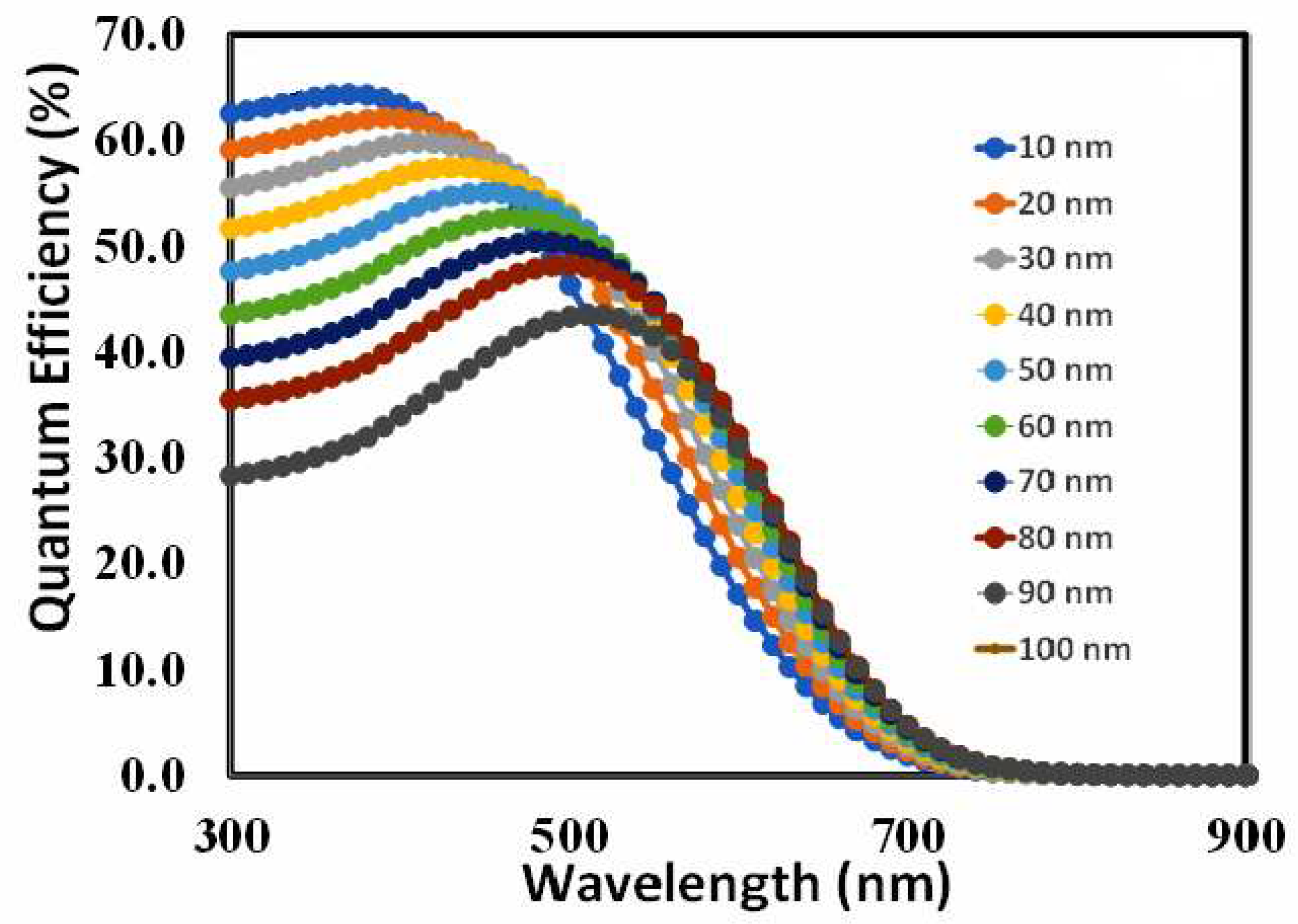
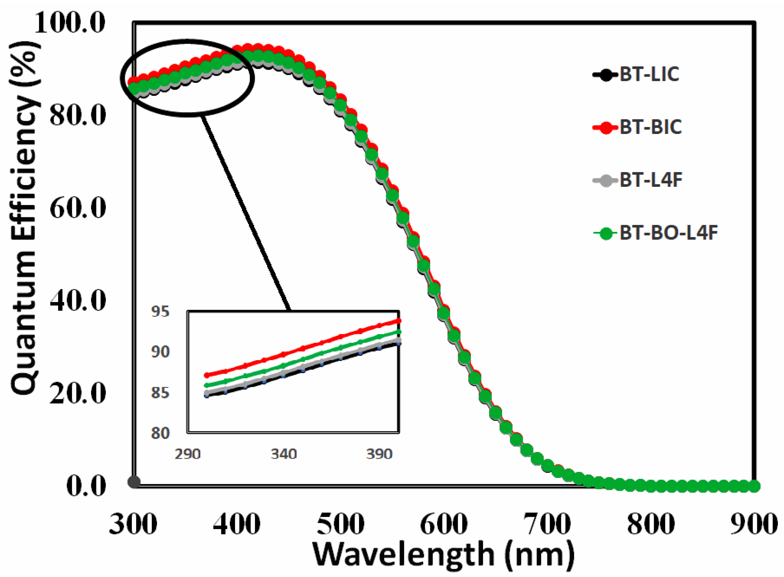
- Step 12, Determination of QE Response of the Optimized Devices: Determine the quantum efficiency of all the optimized devices.
- Step 13, End of Simulation.
5. Simulation Material Parameters
6. Results and Discussion
6.1. Thickness Optimization of the Hole-Transport Layer
6.2. Thickness Optimization of the Absorber Layer
6.3. Thickness Optimization of Electron Transport Layer
- (a)
- Device architecture: The optimal electron transport layer thickness may vary according to the specific device architecture, such as whether the solar cell has a planar or mesoporous structure.
- (b)
- Material characteristics: The ideal thickness for effective charge transfer and extraction can be influenced by the electron transport layer's material characteristics, such as (i) electron transport, (ii) series resistance, (iii) shunt resistance, (iv) carrier lifetime, (v) electron mobility, (vi) electron density, (vii) recombination losses, (viii) charge extraction efficiency, (ix) optical absorption, and (x) interface energy level alignment, among others.
- (c)
- Thin film deposition method: There are several thin-film deposition methods that may be used to manage the electron transport layer's thickness, and each has advantages and limitations of its own. Spin-coating, for instance, is a very cheap and simple method.
- (d)
- Post-deposition method: By modifying the thickness of the electron transport layer using post-deposition techniques like solvent or annealing, the morphology and interface properties of the electron transport layer may be altered.
- (e)
- Photovoltaic performance matrices: Depending on the device's individual performance metrics, such as power conversion efficiency, short circuit current, and fill factor, the ideal electron transport layer thickness may vary. These metrics may all be influenced by the electron transport layer's thickness.
- (f)
- Trade-offs: When determining the ideal electron transport layer thickness, it is frequently necessary to compromise between several device characteristics, such as reducing leakage currents while increasing charge transfer efficiency.
- (g)
- Interaction with other layers: The electron transport layer's thickness can have an impact on how the electrode, absorber layer, and hole transport layer interact with other layers in the device. This might make the optimization procedure more challenging.
6.4. Doping Density Optimization of the Electron Transport Layer
6.5. Photo Current-Voltage Response of the Optimized Devices
6.6. External Quantum Efficiency Response of the Optimized Devices
5. Conclusions
Author Contributions
Funding
Institutional Review Board Statement
Data Availability Statement
Acknowledgments
Conflicts of Interest
References
- Liu, S.; Biju, V. P.; Qi, Y.; Chen, W.; Liu, Z. Recent Progress in the Development of High-Efficiency Inverted Perovskite Solar Cells. NPG Asia Mater 2023, 15, 27. [Google Scholar] [CrossRef]
- Shao, M.; Bie, T.; Yang, L.; Gao, Y.; Jin, X.; He, F.; Zheng, N.; Yu, Y.; Zhang, X. Over 21% Efficiency Stable 2D Perovskite Solar Cells. Advanced Materials 2022, 34. [Google Scholar] [CrossRef]
- Rong, Y.; Hu, Y.; Mei, A.; Tan, H.; Saidaminov, M. I.; Seok, S. Il; McGehee, M. D.; Sargent, E. H.; Han, H. Challenges for Commercializing Perovskite Solar Cells. Science. 2018. [CrossRef] [PubMed]
- Liu, J.; Aydin, E.; Yin, J.; De Bastiani, M.; Isikgor, F. H.; Rehman, A. U.; Yengel, E.; Ugur, E.; Harrison, G. T.; Wang, M.; Gao, Y.; Khan, J. I.; Babics, M.; Allen, T. G.; Subbiah, A. S.; Zhu, K.; Zheng, X.; Yan, W.; Xu, F.; Salvador, M. F.; Bakr, O. M.; Anthopoulos, T. D.; Lanza, M.; Mohammed, O. F.; Laquai, F.; De Wolf, S. 28.2%-Efficient, Outdoor-Stable Perovskite/Silicon Tandem Solar Cell. Joule 2021, 5. [Google Scholar] [CrossRef]
- Babayigit, A.; Ethirajan, A.; Muller, M.; Conings, B. Toxicity of Organometal Halide Perovskite Solar Cells. Nature Materials. 2016. [CrossRef] [PubMed]
- Ding, G.; Zheng, Y.; Xiao, X.; Cheng, H.; Zhang, G.; Shi, Y.; Shao, Y. Sustainable Development of Perovskite Solar Cells: Keeping a Balance between Toxicity and Efficiency. Journal of Materials Chemistry A. 2022. [CrossRef]
- Moiz, S. A.; Alahmadi, A. N. M.; Alshaikh, M. S. Lead-Free FACsSnI3 Based Perovskite Solar Cell: Designing Hole and Electron Transport Layer. Nanomaterials 2023, 13. [Google Scholar] [CrossRef]
- Xu, F.; Zhang, M.; Li, Z.; Yang, X.; Zhu, R. Challenges and Perspectives toward Future Wide-Bandgap Mixed-Halide Perovskite Photovoltaics. Adv Energy Mater 2023, 13. [Google Scholar] [CrossRef]
- Bello, O. O.; Emetere, M. E. Progress and Limitation of Lead-Free Inorganic Perovskites for Solar Cell Application. Solar Energy. 2022. [CrossRef]
- Yu, W.; Zou, Y.; Wang, H.; Qu, B.; Chen, Z.; Xiao, L. Expanding the Absorption of Double Perovskite Cs2AgBiBr6 to NIR Region. J Phys Chem Lett 2023, 14, 5310–5317. [Google Scholar] [CrossRef]
- Zhai, M.; Chen, C.; Cheng, M. Advancing Lead-Free Cs2AgBiBr6 Perovskite Solar Cells: Challenges and Strategies. Solar Energy. 2023. [CrossRef]
- Igbari, F.; Xu, F. F.; Shao, J. Y.; Ud-Din, F.; Siffalovic, P.; Zhong, Y. W. Stacking Interactions and Photovoltaic Performance of Cs2AgBiBr6 Perovskite. Solar RRL. 2023. [CrossRef]
- Momblona, C.; Gil-Escrig, L.; Bandiello, E.; Hutter, E. M.; Sessolo, M.; Lederer, K.; Blochwitz-Nimoth, J.; Bolink, H. J. Efficient Vacuum Deposited P-i-n and n-i-p Perovskite Solar Cells Employing Doped Charge Transport Layers. Energy Environ Sci 2016, 9, 3456–3463. [Google Scholar] [CrossRef]
- Correa-Baena, J. P.; Saliba, M.; Buonassisi, T.; Grätzel, M.; Abate, A.; Tress, W.; Hagfeldt, A. Promises and Challenges of Perovskite Solar Cells. Science. 2017. [CrossRef] [PubMed]
- Foo, S.; Thambidurai, M.; Senthil Kumar, P.; Yuvakkumar, R.; Huang, Y.; Dang, C. Recent Review on Electron Transport Layers in Perovskite Solar Cells. International Journal of Energy Research. 2022. [CrossRef]
- Mohamad Noh, M. F.; Teh, C. H.; Daik, R.; Lim, E. L.; Yap, C. C.; Ibrahim, M. A.; Ahmad Ludin, N.; Mohd Yusoff, A. R. Bin; Jang, J.; Mat Teridi, M. A. The Architecture of the Electron Transport Layer for a Perovskite Solar Cell. Journal of Materials Chemistry C. 2018. [CrossRef]
- Mihailetchi, V. D.; Van Duren, J. K. J.; Blom, P. W. M.; Hummelen, J. C.; Janssen, R. A. J.; Kroon, J. M.; Rispens, M. T.; Verhees, W. J. H.; Wienk, M. M. Electron Transport in a Methanofullerene. Adv Funct Mater 2003, 13. [Google Scholar] [CrossRef]
- Yang, D.; Zhang, X.; Wang, K.; Wu, C.; Yang, R.; Hou, Y.; Jiang, Y.; Liu, S.; Priya, S. Stable Efficiency Exceeding 20.6% for Inverted Perovskite Solar Cells through Polymer-Optimized PCBM Electron-Transport Layers. Nano Lett 2019, 19. [Google Scholar] [CrossRef]
- Karuppuswamy, P.; Hanmandlu, C.; Moorthy Boopathi, K.; Perumal, P.; Liu, C.; Chen, Y.-F.; Chang, Y.-C.; Wang, P.-C.; Lai, C.-S.; Chu, C.-W. Solution-Processable Electron Transport Layer for Efficient Hybrid Perovskite Solar Cells beyond Fullerenes. Solar Energy Materials and Solar Cells 2017, 169, 78–85. [Google Scholar] [CrossRef]
- Saki, Z.; Aitola, K.; Sveinbjörnsson, K.; Yang, W.; Svanström, S.; Cappel, U. B.; Rensmo, H.; Johansson, E. M. J.; Taghavinia, N.; Boschloo, G. The Synergistic Effect of Dimethyl Sulfoxide Vapor Treatment and C60 Electron Transporting Layer towards Enhancing Current Collection in Mixed-Ion Inverted Perovskite Solar Cells. J Power Sources 2018, 405, 70–79. [Google Scholar] [CrossRef]
- Etxebarria, I.; Ajuria, J.; Pacios, R. Polymer:Fullerene Solar Cells: Materials, Processing Issues, and Cell Layouts to Reach Power Conversion Efficiency over 10%, a Review. J Photonics Energy 2015, 5, 57214. [Google Scholar] [CrossRef]
- Wang, D.; Ye, T.; Zhang, Y. Recent Advances of Non-Fullerene Organic Electron Transport Materials in Perovskite Solar Cells. J Mater Chem A Mater 2020, 8. [Google Scholar] [CrossRef]
- Heo, J. H.; Lee, S.-C.; Jung, S.-K.; Kwon, O.-P.; Im, S. H. Efficient and Thermally Stable Inverted Perovskite Solar Cells by Introduction of Non-Fullerene Electron Transporting Materials. J Mater Chem A Mater 2017, 5, 20615–20622. [Google Scholar] [CrossRef]
- Padula, D.; Landi, A.; Prampolini, G. Assessing Alkyl Side Chain Effects on Electron Transport Properties of Y6-Derived Non-Fullerene Acceptors. Energy Advances 2023. [Google Scholar] [CrossRef]
- Cao, X.; Li, P.; Zhu, X.; Li, H.; Xu, R.; Li, J.; Ma, L.; Dong, H.; Wu, Z. Nonfullerene Agent Enables Efficient and Stable Tin-Based Perovskite Solar Cells. Solar RRL 2023, 7, 2300268. [Google Scholar] [CrossRef]
- Lin, Y.; Wang, J.; Zhang, Z. G.; Bai, H.; Li, Y.; Zhu, D.; Zhan, X. An Electron Acceptor Challenging Fullerenes for Efficient Polymer Solar Cells. Advanced Materials 2015, 27. [Google Scholar] [CrossRef] [PubMed]
- Zhou, D.; Wang, J.; Xu, Z.; Xu, H.; Quan, J.; Deng, J.; Li, Y.; Tong, Y.; Hu, B.; Chen, L. Recent Advances of Nonfullerene Acceptors in Organic Solar Cells. Nano Energy. 2022. [CrossRef]
- Wei, Q.; Liu, W.; Leclerc, M.; Yuan, J.; Chen, H.; Zou, Y. A-DA′D-A Non-Fullerene Acceptors for High-Performance Organic Solar Cells. Sci China Chem 2020, 63, 1352–1366. [Google Scholar] [CrossRef]
- Yuan, J.; Zhang, Y.; Zhou, L.; Zhang, G.; Yip, H.-L.; Lau, T.-K.; Lu, X.; Zhu, C.; Peng, H.; Johnson, P. A.; Leclerc, M.; Cao, Y.; Ulanski, J.; Li, Y.; Zou, Y. Single-Junction Organic Solar Cell with over 15% Efficiency Using Fused-Ring Acceptor with Electron-Deficient Core. Joule 2019, 3, 1140–1151. [Google Scholar] [CrossRef]
- Cui, Y.; Yao, H.; Zhang, J.; Xian, K.; Zhang, T.; Hong, L.; Wang, Y.; Xu, Y.; Ma, K.; An, C.; He, C.; Wei, Z.; Gao, F.; Hou, J. Single-Junction Organic Photovoltaic Cells with Approaching 18% Efficiency. Advanced Materials 2020, 32. [Google Scholar] [CrossRef]
- Zhu, C.; Yuan, J.; Cai, F.; Meng, L.; Zhang, H.; Chen, H.; Li, J.; Qiu, B.; Peng, H.; Chen, S.; Hu, Y.; Yang, C.; Gao, F.; Zou, Y.; Li, Y. Tuning the Electron-Deficient Core of a Non-Fullerene Acceptor to Achieve over 17% Efficiency in a Single-Junction Organic Solar Cell. Energy Environ Sci 2020, 13, 2459–2466. [Google Scholar] [CrossRef]
- Cai, Y.; Li, Y.; Wang, R.; Wu, H.; Chen, Z.; Zhang, J.; Ma, Z.; Hao, X.; Zhao, Y.; Zhang, C.; Huang, F.; Sun, Y. A Well-Mixed Phase Formed by Two Compatible Non-Fullerene Acceptors Enables Ternary Organic Solar Cells with Efficiency over 18.6%. Advanced Materials 2021, 33, 2101733. [Google Scholar] [CrossRef] [PubMed]
- Liu, Q.; Jiang, Y.; Jin, K.; Qin, J.; Xu, J.; Li, W.; Xiong, J.; Liu, J.; Xiao, Z.; Sun, K.; Yang, S.; Zhang, X.; Ding, L. 18% Efficiency Organic Solar Cells. Sci Bull (Beijing) 2020, 65. [Google Scholar] [CrossRef] [PubMed]
- Jin, K.; Xiao, Z.; Ding, L. 18.69% PCE from Organic Solar Cells. Journal of Semiconductors. 2021. [CrossRef]
- Li, S.; Ye, L.; Zhao, W.; Zhang, S.; Mukherjee, S.; Ade, H.; Hou, J. Energy-Level Modulation of Small-Molecule Electron Acceptors to Achieve over 12% Efficiency in Polymer Solar Cells. Advanced Materials 2016, 28. [Google Scholar] [CrossRef] [PubMed]
- Lin, Y.; He, Q.; Zhao, F.; Huo, L.; Mai, J.; Lu, X.; Su, C. J.; Li, T.; Wang, J.; Zhu, J.; Sun, Y.; Wang, C.; Zhan, X. A Facile Planar Fused-Ring Electron Acceptor for As-Cast Polymer Solar Cells with 8.71% Efficiency. J Am Chem Soc 2016, 138. [Google Scholar] [CrossRef] [PubMed]
- Pan, H.; Zhao, X.; Gong, X.; Li, H.; Ladi, N. H.; Zhang, X. L.; Huang, W.; Ahmad, S.; Ding, L.; Shen, Y.; Wang, M.; Fu, Y. Advances in Design Engineering and Merits of Electron Transporting Layers in Perovskite Solar Cells. Mater Horiz 2020, 7. [Google Scholar] [CrossRef]
- Mahmood, K.; Sarwar, S.; Mehran, M. T. Current Status of Electron Transport Layers in Perovskite Solar Cells: Materials and Properties. RSC Advances. 2017. [CrossRef]
- Saif, O. M.; Elogail, Y.; Abdolkader, T. M.; Shaker, A.; Zekry, A.; Abouelatta, M.; Salem, M. S.; Fedawy, M. Comprehensive Review on Thin Film Homojunction Solar Cells: Technologies, Progress and Challenges. Energies (Basel) 2023, 16. [Google Scholar] [CrossRef]
- Bagade, S. S.; Barik, S. B.; Malik, M. M.; Patel, P. K. Impact of Band Alignment at Interfaces in Perovskite-Based Solar Cell Devices. Mater Today Proc 2023. [Google Scholar] [CrossRef]
- Ma, L.; Zhang, S.; Hou, J. Crystal Structures in State-of-the-Art Non-Fullerene Electron Acceptors. Journal of Materials Chemistry A. 2022. [CrossRef]
- Li, G.; Zhang, X.; Jones, L. O.; Alzola, J. M.; Mukherjee, S.; Feng, L. W.; Zhu, W.; Stern, C. L.; Huang, W.; Yu, J.; Sangwan, V. K.; Delongchamp, D. M.; Kohlstedt, K. L.; Wasielewski, M. R.; Hersam, M. C.; Schatz, G. C.; Facchetti, A.; Marks, T. J. Systematic Merging of Nonfullerene Acceptor π-Extension and Tetrafluorination Strategies Affords Polymer Solar Cells with >16% Efficiency. J Am Chem Soc 2021, 143. [Google Scholar] [CrossRef] [PubMed]
- Xin, J.; Li, W.; Zhang, Y.; Liang, Q.; Song, C.; Zhao, Y.; He, Z.; Liu, J.; Ma, W. A Review of Nonfullerene Solar Cells: Insight into the Correlation among Molecular Structure, Morphology, and Device Performance. Battery Energy 2023, 2. [Google Scholar] [CrossRef]
- Liang, C.; Xing, G. Doping Electron Transporting Layer: An Effective Method to Enhance JSC of All-Inorganic Perovskite Solar Cells. ENERGY & ENVIRONMENTAL MATERIALS 2021, 4, 500–501. [Google Scholar] [CrossRef]
- Lee, S.; Paine, D. C.; Gleason, K. K. Heavily Doped Poly(3,4-Ethylenedioxythiophene) Thin Films with High Carrier Mobility Deposited Using Oxidative CVD: Conductivity Stability and Carrier Transport. Adv Funct Mater 2014, 24, 7187–7196. [Google Scholar] [CrossRef]
- Xu, Z.; Li, N.; Niu, X.; Liu, H.; Liu, G.; Chen, Q.; Zhou, H. Balancing Energy-Level Difference for Efficient n-i-p Perovskite Solar Cells with Cu Electrode. Energy Material Advances 2022, 2022. [Google Scholar] [CrossRef]
- Wu, X.; Li, B.; Zhu, Z.; Chueh, C. C.; Jen, A. K. Y. Designs from Single Junctions, Heterojunctions to Multijunctions for High-Performance Perovskite Solar Cells. Chemical Society Reviews. 2021. [CrossRef]
- Zhang, S.; Liu, Z.; Zhang, W.; Jiang, Z.; Chen, W.; Chen, R.; Huang, Y.; Yang, Z.; Zhang, Y.; Han, L.; Chen, W. Barrier Designs in Perovskite Solar Cells for Long-Term Stability. Advanced Energy Materials. 2020. [CrossRef]
- Fan, R.; Huang, Y.; Wang, L.; Li, L.; Zheng, G.; Zhou, H. The Progress of Interface Design in Perovskite-Based Solar Cells. Adv Energy Mater 2016, 6. [Google Scholar] [CrossRef]
- Hossain, M. K.; Samajdar, D. P.; Das, R. C.; Arnab, A. A.; Rahman, M. F.; Rubel, M. H. K.; Islam, M. R.; Bencherif, H.; Pandey, R.; Madan, J.; Mohammed, M. K. A. Design and Simulation of Cs2BiAgI6 Double Perovskite Solar Cells with Different Electron Transport Layers for Efficiency Enhancement. Energy and Fuels 2023, 37. [Google Scholar] [CrossRef]
- Mali, S. S.; Hong, C. K. P-i-n/n-i-p Type Planar Hybrid Structure of Highly Efficient Perovskite Solar Cells towards Improved Air Stability: Synthetic Strategies and the Role of p-Type Hole Transport Layer (HTL) and n-Type Electron Transport Layer (ETL) Metal Oxides. Nanoscale 2016, 8, 10528–10540. [Google Scholar] [CrossRef]
- Wu, S.; Liu, M.; Jen, A. K. Y. Prospects and Challenges for Perovskite-Organic Tandem Solar Cells. Joule. 2023. [CrossRef]
- Sun, K.; Zhang, S.; Li, P.; Xia, Y.; Zhang, X.; Du, D.; Isikgor, F. H.; Ouyang, J. Review on Application of PEDOTs and PEDOT:PSS in Energy Conversion and Storage Devices. Journal of Materials Science: Materials in Electronics 2015, 26, 4438–4462. [Google Scholar] [CrossRef]
- Liu, F.; Zhu, J.; Wei, J.; Li, Y.; Lv, M.; Yang, S.; Zhang, B.; Yao, J.; Dai, S. Numerical Simulation: Toward the Design of High-Efficiency Planar Perovskite Solar Cells. Appl Phys Lett 2014, 104. [Google Scholar] [CrossRef]
- Neukom, M. T.; Schiller, A.; Züfle, S.; Knapp, E.; Ávila, J.; Pérez-del-Rey, D.; Dreessen, C.; Zanoni, K. P. S.; Sessolo, M.; Bolink, H. J.; Ruhstaller, B. Consistent Device Simulation Model Describing Perovskite Solar Cells in Steady-State, Transient, and Frequency Domain. ACS Appl Mater Interfaces 2019, 11, 23320–23328. [Google Scholar] [CrossRef] [PubMed]
- Gummel, H. K. A Self-Consistent Iterative Scheme for One-Dimensional Steady State Transistor Calculations. IEEE Trans Electron Devices 1964, 11. [Google Scholar] [CrossRef]
- Gwyn, C. W.; Scharfetter, D. L.; Wirth, J. L. The Analysis of Radiation Effects in Semiconductor Junction Devices. IEEE Trans Nucl Sci 1967, NS-14. [Google Scholar] [CrossRef]
- Burgelman, M.; Nollet, P.; Degrave, S. Modelling Polycrystalline Semiconductor Solar Cells. Thin Solid Films 2000, 361. [Google Scholar] [CrossRef]
- Liu, Y.; Sun, Y.; Rockett, A. A New Simulation Software of Solar Cells - WxAMPS. Solar Energy Materials and Solar Cells 2012, 98. [Google Scholar] [CrossRef]
- Moiz, S. A. Optimization of Hole and Electron Transport Layer for Highly Efficient Lead-Free Cs2TiBr6-Based Perovskite Solar Cell. Photonics 2022, 9. [Google Scholar] [CrossRef]
- Moiz, S. A.; Alahmadi, A. N. M. Design of Dopant and Lead-Free Novel Perovskite Solar Cell for 16.85% Efficiency. Polymers (Basel) 2021, 13. [Google Scholar] [CrossRef]
- Burgelman, M.; Decock, K.; Khelifi, S.; Abass, A. Advanced Electrical Simulation of Thin Film Solar Cells. In Thin Solid Films; 2013; Vol. 535. [CrossRef]
- Burgelman, M.; Verschraegen, J.; Degrave, S.; Nollet, P. Modeling Thin-Film PV Devices. Progress in Photovoltaics: Research and Applications 2004, 12, (2–3). [Google Scholar] [CrossRef]
- Verschraegen, J.; Burgelman, M. Numerical Modeling of Intra-Band Tunneling for Heterojunction Solar Cells in Scaps. Thin Solid Films 2007, 515. [Google Scholar] [CrossRef]
- He, Y.; Xu, L.; Yang, C.; Guo, X.; Li, S. Design and Numerical Investigation of a Lead-Free Inorganic Layered Double Perovskite Cs4cusb2cl12 Nanocrystal Solar Cell by Scaps-1d. Nanomaterials 2021, 11. [Google Scholar] [CrossRef] [PubMed]
- Chowdhury, M. S.; Shahahmadi, S. A.; Chelvanathan, P.; Tiong, S. K.; Amin, N.; Techato, K.; Nuthammachot, N.; Chowdhury, T.; Suklueng, M. Effect of Deep-Level Defect Density of the Absorber Layer and n/i Interface in Perovskite Solar Cells by SCAPS-1D. Results in Physics. 2020. [CrossRef]
- Moiz, S. A.; Albadwani, S. A.; Alshaikh, M. S. Towards Highly Efficient Cesium Titanium Halide Based Lead-Free Double Perovskites Solar Cell by Optimizing the Interface Layers. Nanomaterials 2022, 12. [Google Scholar] [CrossRef]
- Moiz, S. A.; Alzahrani, M. S.; Alahmadi, A. N. M. Electron Transport Layer Optimization for Efficient PTB7:PC70BM Bulk-Heterojunction Solar Cells. Polymers (Basel) 2022, 14. [Google Scholar] [CrossRef]
- Moiz, S. A.; Alahmadi, A. N. M.; Aljohani, A. J. Design of a Novel Lead-Free Perovskite Solar Cell for 17.83% Efficiency. IEEE Access 2021, 9. [Google Scholar] [CrossRef]
- McClure, E. T.; Ball, M. R.; Windl, W.; Woodward, P. M. Cs2AgBiX6 (X = Br, Cl): New Visible Light Absorbing, Lead-Free Halide Perovskite Semiconductors. Chemistry of Materials 2016, 28. [Google Scholar] [CrossRef]
- Amri, K.; Belghouthi, R.; Aillerie, M.; Gharbi, R. Device Optimization of a Lead-Free Perovskite/Silicon Tandem Solar Cell with 24.4% Power Conversion Efficiency. Energies (Basel) 2021, 14. [Google Scholar] [CrossRef]
- Zhang, G.; Lin, F. R.; Qi, F.; Heumüller, T.; Distler, A.; Egelhaaf, H. J.; Li, N.; Chow, P. C. Y.; Brabec, C. J.; Jen, A. K. Y.; Yip, H. L. Renewed Prospects for Organic Photovoltaics. Chemical Reviews. 2022. [CrossRef] [PubMed]
- Liu, H.; Dai, T.; Zhou, J.; Wang, H.; Guo, Q.; Guo, Q.; Zhou, E. The Development of A-DA’D-A Type Nonfullerene Acceptors Containing Non-Halogenated End Groups. Nano Res 2023. [Google Scholar] [CrossRef]
- Perdigón-Toro, L.; Zhang, H.; Markina, A.; Yuan, J.; Hosseini, S. M.; Wolff, C. M.; Zuo, G.; Stolterfoht, M.; Zou, Y.; Gao, F.; Andrienko, D.; Shoaee, S.; Neher, D. Barrierless Free Charge Generation in the High-Performance PM6:Y6 Bulk Heterojunction Non-Fullerene Solar Cell. Advanced Materials 2020, 32. [Google Scholar] [CrossRef] [PubMed]
- Shi, T.; Zhang, H. S.; Meng, W.; Teng, Q.; Liu, M.; Yang, X.; Yan, Y.; Yip, H. L.; Zhao, Y. J. Effects of Organic Cations on the Defect Physics of Tin Halide Perovskites. J Mater Chem A Mater 2017, 5. [Google Scholar] [CrossRef]
- Cao, W.; Hu, Z.; Lin, Z.; Guo, X.; Su, J.; Chang, J.; Hao, Y. Defects and Doping Engineering towards High Performance Lead-Free or Lead-Less Perovskite Solar Cells. Journal of Energy Chemistry. 2022. [CrossRef]
- Friedel, B.; Keivanidis, P. E.; Brenner, T. J. K.; Abrusci, A.; McNeill, C. R.; Friend, R. H.; Greenham, N. C. Effects of Layer Thickness and Annealing of PEDOT:PSS Layers in Organic Photodetectors. Macromolecules 2009, 42, 6741–6747. [Google Scholar] [CrossRef]
- Moiz, S. A.; Khan, I. A.; Younis, W. A.; Masud, M. I.; Ismail, Y.; Khawaja, Y. M. Solvent Induced Charge Transport Mechanism for Conducting Polymer at Higher Temperature. Mater Res Express 2020, 7. [Google Scholar] [CrossRef]
- Karimov, Kh. S.; Ahmed, M. M.; Moiz, S. A.; Babadzhanov, P.; Marupov, R.; Turaeva, M. A. Electrical Properties of Organic Semiconductor Orange Nitrogen Dye Thin Films Deposited from Solution at High Gravity. Eurasian Chemico-Technological Journal 2007, 5. [Google Scholar] [CrossRef]
- Sherkar, T. S.; Momblona, C.; Gil-Escrig, L.; Ávila, J.; Sessolo, M.; Bolink, H. J.; Koster, L. J. A. Recombination in Perovskite Solar Cells: Significance of Grain Boundaries, Interface Traps, and Defect Ions. ACS Energy Lett 2017, 2. [Google Scholar] [CrossRef] [PubMed]
- Moiz, S. A.; Alahmadi, A. N. M.; Aljohani, A. J. Design of Silicon Nanowire Array for PEDOT:PSS-Silicon Nanowire-Based Hybrid Solar Cell. Energies (Basel) 2020, 13. [Google Scholar] [CrossRef]
- Della Gaspera, E.; Peng, Y.; Hou, Q.; Spiccia, L.; Bach, U.; Jasieniak, J. J.; Cheng, Y. B. Ultra-Thin High Efficiency Semitransparent Perovskite Solar Cells. Nano Energy 2015, 13. [Google Scholar] [CrossRef]
- Brendel, R.; Queisser, H. J. On the Thickness Dependence of Open Circuit Voltages of P-n Junction Solar Cells. Solar Energy Materials and Solar Cells 1993, 29, 397–401. [Google Scholar] [CrossRef]
- Zhang, C.; Zhu, X. N-Type Quinoidal Oligothiophene-Based Semiconductors for Thin-Film Transistors and Thermoelectrics. Advanced Functional Materials. 2020. [CrossRef]
- Naab, B. D.; Gu, X.; Kurosawa, T.; To, J. W. F.; Salleo, A.; Bao, Z. Role of Polymer Structure on the Conductivity of N-Doped Polymers. Adv Electron Mater 2016, 2. [Google Scholar] [CrossRef]
- Moiz, S. A.; Alahmadi, A. N. M.; Karimov, K. S. Improved Organic Solar Cell by Incorporating Silver Nanoparticles Embedded Polyaniline as Buffer Layer. Solid State Electron 2020, 163. [Google Scholar] [CrossRef]
- Guo, Z.; Jena, A. K.; Kim, G. M.; Miyasaka, T. The High Open-Circuit Voltage of Perovskite Solar Cells: A Review. Energy Environ. Sci. 2022, 15, 3171–3222. [Google Scholar] [CrossRef]
- Shao, Y.; Yuan, Y.; Huang, J. Correlation of Energy Disorder and Open-Circuit Voltage in Hybrid Perovskite Solar Cells. Nat Energy 2016, 1. [Google Scholar] [CrossRef]
- Shaheen, S. E.; Brabec, C. J.; Sariciftci, N. S.; Padinger, F.; Fromherz, T.; Hummelen, J. C. 2.5% Efficient Organic Plastic Solar Cells. Appl Phys Lett 2001, 78, 841–843. [Google Scholar] [CrossRef]

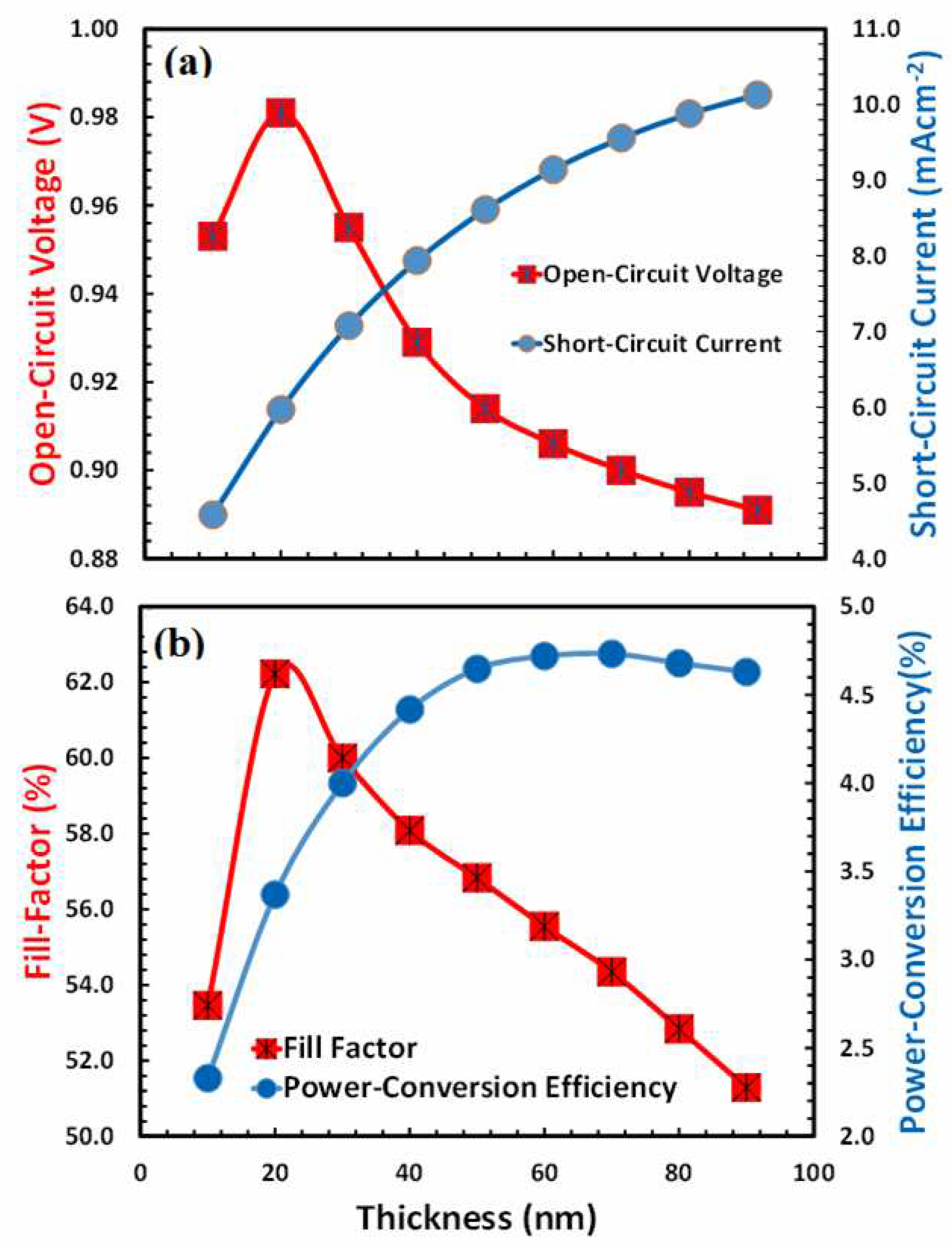
 ), short-circuit current (
 ), (b) fill factor (
 ), and power-conversion efficiency (
 ) of Device D as a function of the thickness of the PEDOT:PSS as hole-transport layer.
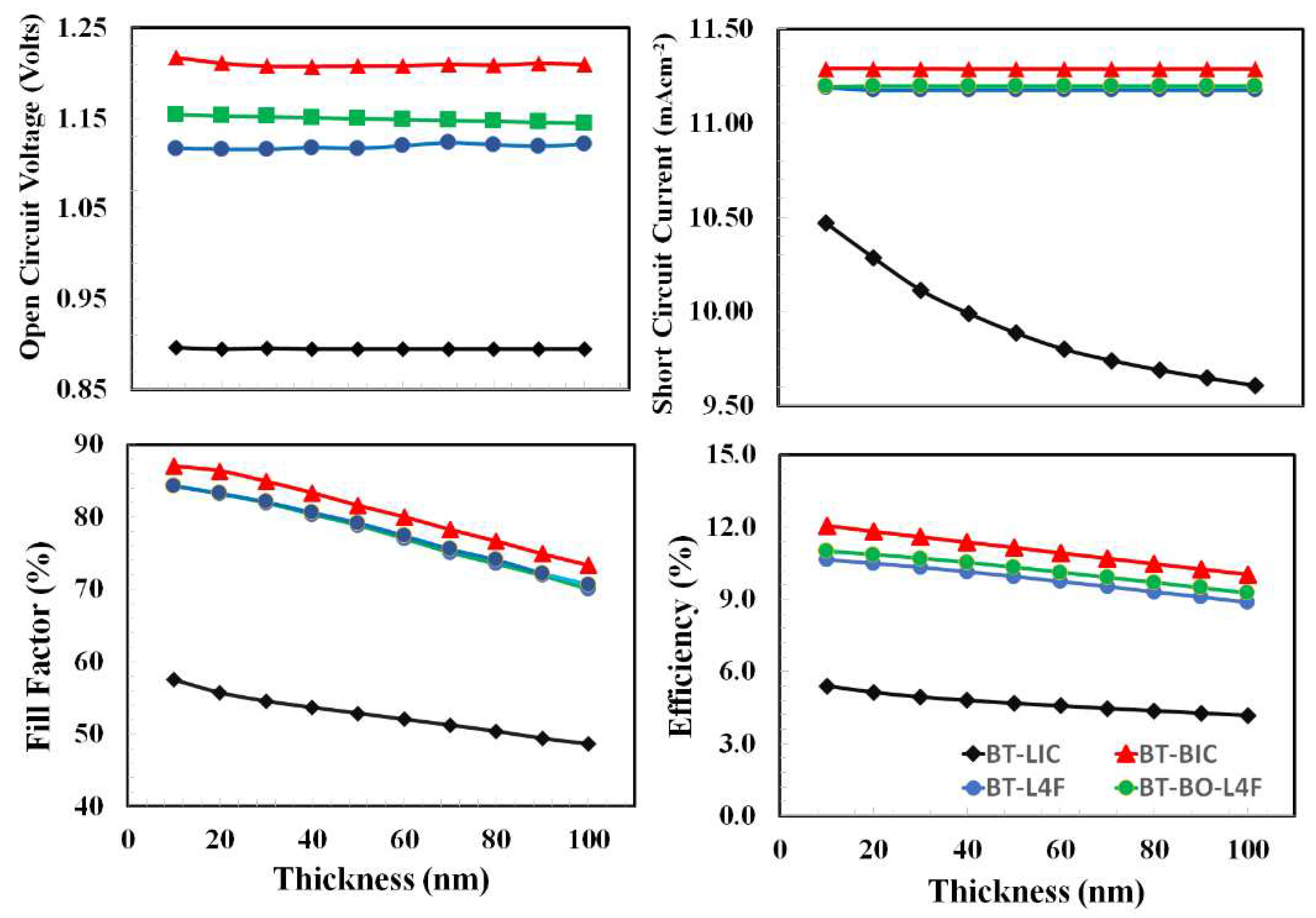
 ), short-circuit current (
 ), (b) fill factor (
 ), and power-conversion efficiency (
 ) of Device D as a function of the thickness of the PEDOT:PSS as hole-transport layer.
| Photovoltaic Parameters | PEDOT: PSS | Perovskite Cs2AgBi0.75Sb0.25Br6 |
BT- LIC | BT- BIC | BT- L4F | BT- BO-L4F |
|---|---|---|---|---|---|---|
| Thickness (nm) | 50 | 500 | 100 | 100 | 100 | 100 |
| Energy Band Gap (Eg, eV) | 2.2 | 1.8 | 1.57 | 1.73 | 1.58 | 1.6 |
| Electron Affinity (X, eV) | 2.9 | 3.58 | 3.85 | 3.73 | 4 | 3.98 |
| Dielectric Permittivity () | 3.0 | 6.5 | 3.5 | 3.5 | 3.5 | 3.5 |
| Effective Density of States at Conduction Band (Nc , cm-3 ) | 2.2x10¹⁵ | 2.2x10¹⁸ | 1x10²⁰ | 1x10²⁰ | 1x10²⁰ | 1x10²⁰ |
| Effective Density of States at Valence Band (Nv , cm-3 ) | 1.8 x 10¹⁸ | 1.8 x 10¹⁹ | 1x10²⁰ | 1x10²⁰ | 1 x10²⁰ | 1x10²⁰ |
| Hole Thermal Velocity (Vh, cm/s) | 1x10⁷ | 1x10⁷ | 1x10⁷ | 1x10⁷ | 1x10⁷ | 1x10⁷ |
| Electron Thermal Velocity (Ve, cm/s) | 1x10⁷ | 1x10⁷ | 1x10⁷ | 1x10⁷ | 1x10⁷ | 1x10⁷ |
| Electron Mobility (, cm-2/V.s) | 10 | 2 | 1x10⁻⁴ | 1x10⁻⁴ | 1x10⁻⁴ | 1x10⁻⁴ |
| Hole Mobility (, cm-2/V.s) | 10 | 2 | 4x10⁻⁴ | 1x10⁻⁴ | 1x10⁻⁴ | 1x10⁻⁴ |
| Uniform Shallow Donor Doping (Nd,,cm-3) | - | - | 1x10¹⁶ | 1x10¹⁶ | 1x10¹⁶ | 1x10¹⁶ |
| Uniform Shallow Acceptor Doping (Na, cm-3 ) | 1015 | - | 1x10¹⁶ | - | - | - |
| Defect Density (Nt, cm-3 ) | 1014 | 1014 | 1014 | 1014 | 1014 | 1014 |
| Reference | [64,65,66,67,68] | [69,70,71] | [72,73] |
| Device | Open-Circuit Voltage (Volts) |
Short-Circuit Current (mA.cm-2 ) | Fill-Factor (%) | Power-Conversion Efficiency (%) |
|---|---|---|---|---|
| Devise A (BT-LIC) | 1.23 | 11.2 | 50 | 6.8 |
| Devise B (BT-LIC) | 1.36 | 12.1 | 80 | 13.2 |
| Devise C (BT-L4F) | 1.26 | 12.01 | 71 | 10.7 |
| Devise D (BT-BO-L4F) | 1.24 | 12.5 | 78 | 12.09 |
Disclaimer/Publisher’s Note: The statements, opinions and data contained in all publications are solely those of the individual author(s) and contributor(s) and not of MDPI and/or the editor(s). MDPI and/or the editor(s) disclaim responsibility for any injury to people or property resulting from any ideas, methods, instructions or products referred to in the content. |
© 2023 by the authors. Licensee MDPI, Basel, Switzerland. This article is an open access article distributed under the terms and conditions of the Creative Commons Attribution (CC BY) license (https://creativecommons.org/licenses/by/4.0/).


