1. Introduction
The proliferation of wireless communication technologies is experiencing an ever-increasing demand for high data rates and low link latencies. The 5G new-radio standard marks an inflection point enabling seamless wireless coverage particularly for automated and connected driving on roads and rails, and across borders [
1]. Intelligent transportation systems and safety considerations require vehicle connectivity anytime and anywhere. The effects of multipath propagation like shadowing and dispersive channel properties challenge the link coverage at 5G frequencies especially in the frequency range FR2 (24.25…52.6 GHz). 5G low-earth orbit (LEO) satellite communications-on-the-move establishing non-terrestrial network (NTN) links have emerged as a promising asset for providing global wireless coverage to a broad variety of moving platforms where terrestrial network (TN) infrastructure may not be available or feasible. Moreover, the satellite links operate independently and thus enable scaling of the performance figures of existing TN. The aim is thus to merge terrestrial and non-terrestrial networks and to provide technical solutions for implementation.
LEO satellite communications at orbital heights of d = 150…2000 km have broadened the research interest due to their relevance for a seamless worldwide coverage. Such links provide attractive features such as smaller path loss, higher area capacity, lower latency, lower power consumption, and reduced launching costs when compared with higher-orbit satellite constellations [
2]. However, satellite connectivity poses severe challenges with respect to the link budget and the user equipment (UE) terminal antennas [
3]. The first consideration refers to the potential frequency ranges enabling efficient 5G LEO satellite communications. Different spectral ranges at low (S-band), mid (Ku-band), and high (Ka-band) frequencies were compared by the authors previously in terms of selected key-performance indicators (KPI) such as uplink (UL) and downlink (DL) data rates, UE antenna size, terminal costs, and chipset availability for a given satellite constellation [
4]. The low-band spectrum is considered well suited for 5G applications due to its moderate technical complexity, attractive link budget, and affordable costs; on the contrary, the high-band spectrum promises high data rates and compact terminal sizes. The authors deduced that both S-band and Ka-bands seem promising candidates for effective 5G LEO satellite communications, especially in view of their compatibility with 3GPP standards. The second step concerns suitable antenna terminals, offering compact designs, integrable into the vehicles, and simple to fabricate for faster acceptance in the automotive mass market. The availability of high-gain mega constellations opens the potential to employ low-profile UE antennas with moderate gain and without the necessity of beam tracking [
4].
Accordingly, compact and low-profile antennas become indispensable and could possibly benefit from the increasing popularity of conformal plastic-embedded antennas for automotive applications. High-gain antennas with dynamic beam tracking for satellite communications were developed in [
5,
6] but they do not appear feasible for automotive mass-market applications due to their power consumption, costs, complexity, and volume. A promising technique to embed less complex antennas invisibly into plastic parts of passenger cars was presented in [
7,
8] for separate TN and NTN functionality; this approach suffers from polarization loss as the antennas were linearly polarized (LP), while circular polarization (CP) is more appropriate to mitigate mulitpath propagation in satellite communication links [
9]. Microstrip patch antennas are the first choice for this application because of their ease of manufacturing and compactness. The excitation of circular polarization over sufficiently wide bandwidths and angular ranges requires a thorough design of the feed network for the arrays. Sequential rotation is a promising approach as it offers wide impedance bandwidth and 3-dB axial-ratio bandwidth [
10].
This article presents a dual-band nested circularly polarized antenna terminal for non-terrestrial automotive 5G applications operating in the n78 band (3.3…3.8 GHz) and, at the same time, in the n257 band (26.5…29.5 GHz) band. The two bands were selected based on the aforementioned KPI and cover both the UL and DL frequency bands according to 3GPP [
11]. The antenna combines a 2×2 aperture-coupled patch array for the lower band and a 4×4 single-layer patch array for the higher band. The focus of this paper is on the design of the former, while the latter was presented in [
12]. The nested dual-band UE antenna array design makes it easy to manufacture, and its low profile lends well to mounting locations such as the rear spoiler of a car, roof-top shark-fin antenna cavities, or other similar mounting locations.
The article is divided as follows.
Section 2 outlines the link budget and the resulting antenna specifications.
Section 3 describes the proposed nested antenna array design. The results for numerical simulations and measurements are summarized in section 4, followed by conclusions in section 5.
2. User Terminal Specifications
2.1. Link Budget Analysis
The analysis of the link budget is common practice to estimate the end-to-end performance of wireless links in UL and DL. The technical specifications of ground terminals such as gain and radiation pattern can be lowered by considering suitable satellite constellation geometries and satellite antenna configurations. A sample uplink budget for the n78-band is detailed in
Table 1. We consider very low earth-orbit (VLEO) constellations with orbital heights of d = 400…500 km and multi-beam antenna arrays with sufficient gains at the edge of the coverage area. Given a 3-dB beamwidth Θ
sat = 2°, a satellite antenna edge gain of G
sat = 38.3 dBi was calculated at the center frequency f = 3.5 GHz [
13]. A moderate UE antenna gain of G
UE =10 dBi has been considered to keep the terminal simple, and cost efficient. The n78-band is less prone to atmospheric losses than at higher frequencies, represented by α
atm = 3.5 dB [
2]. According to these data, we anticipate an uplink data rate of DR = 21 Mbit/s at f = 3.5 GHz, which can be achieved even with a moderate gain of G
UE = 10 dBi. For the higher n257-band, a sample link budget was presented by the authors in [
12], where an uplink data rate of DR = 7 Mbit/s at f = 28.5 GHz was anticipated for a moderate gain of G
UE = 15 dBi and hence low complexity of the UE antenna.
Data rates of this order can be meaningfully utilized for several automotive use cases [
14]. For instance, “sharing and collection of high-definition maps” demand uplink DR = 4 Mbit/s and downlink DR = 16 Mbit/s with a link latency of up to L = 100 ms. The “obstructed view assist” provides a host vehicle with an alternate view of obstructed road segment, requiring DR = 5 Mbit/s and L = 50 ms. Patient transport vehicles sharing vital patient telemetry data, images, voice and video between paramedics and patient monitoring personnel necessitate DR = 8.1 Mbit/s with service latency L = 150 ms. The firm-ware update of reconfigurable radio systems to comply with regional requirements necessitates a data rate DR = 0.3…3.3 Mbit/s without any critical requirement of latency.
2.2. Antenna Specifications
The gain of the UE antenna plays a decisive role in defining the achievable data rate according to the aforementioned link budget parameters but, at the same time, determines the complexity of the resulting terminal.
Table 2 presents additional performance parameters that have to be considered in the UE antenna design. According to 3GPP, the UE antenna should cover at least a bandwidth of B
op = 400 MHz at the n78- and n257-bands around their respective center frequencies f = 3.5 and f = 28 GHz [
11]. In order to limit the polarization loss, axial ratios AR < 3 dB would be considered suitable [
15]. Finally, the width and direction of the main beam, Θ
UE, must be considered appropriately so that the resulting field-of-view is covered with respect to spectral and angular masks and adequate gain. Our aim is to achieve Θ
UE = ±30° by considering G
UE = 10…15 dBi as attractive target values for efficient 5G automotive satellite communications.
3. Dual-Band Nested Antenna Array Design
3.1. Antenna Array for 3.5 GHz
The geometry of the proposed CP single-element square patch antenna covering the n78-band consists of a multilayer structure utilizing an aperture-coupled feeding technique. The radiating patch is placed on Isola Astra® MT77 substrate with a thickness of h = 0.51 mm, a dielectric constant ε
r = 3 (stable up to W-band frequencies), and a loss tangent tan(δ) = 0.0017 [
16]. The microstrip transmission line is fed at the bottom side of a Rogers RT 6010LM substrate with a thickness of h = 0.64 mm, dielectric constant ε
r = 10.2, and a loss tangent tan(δ) = 0.0023 at 10 GHz [
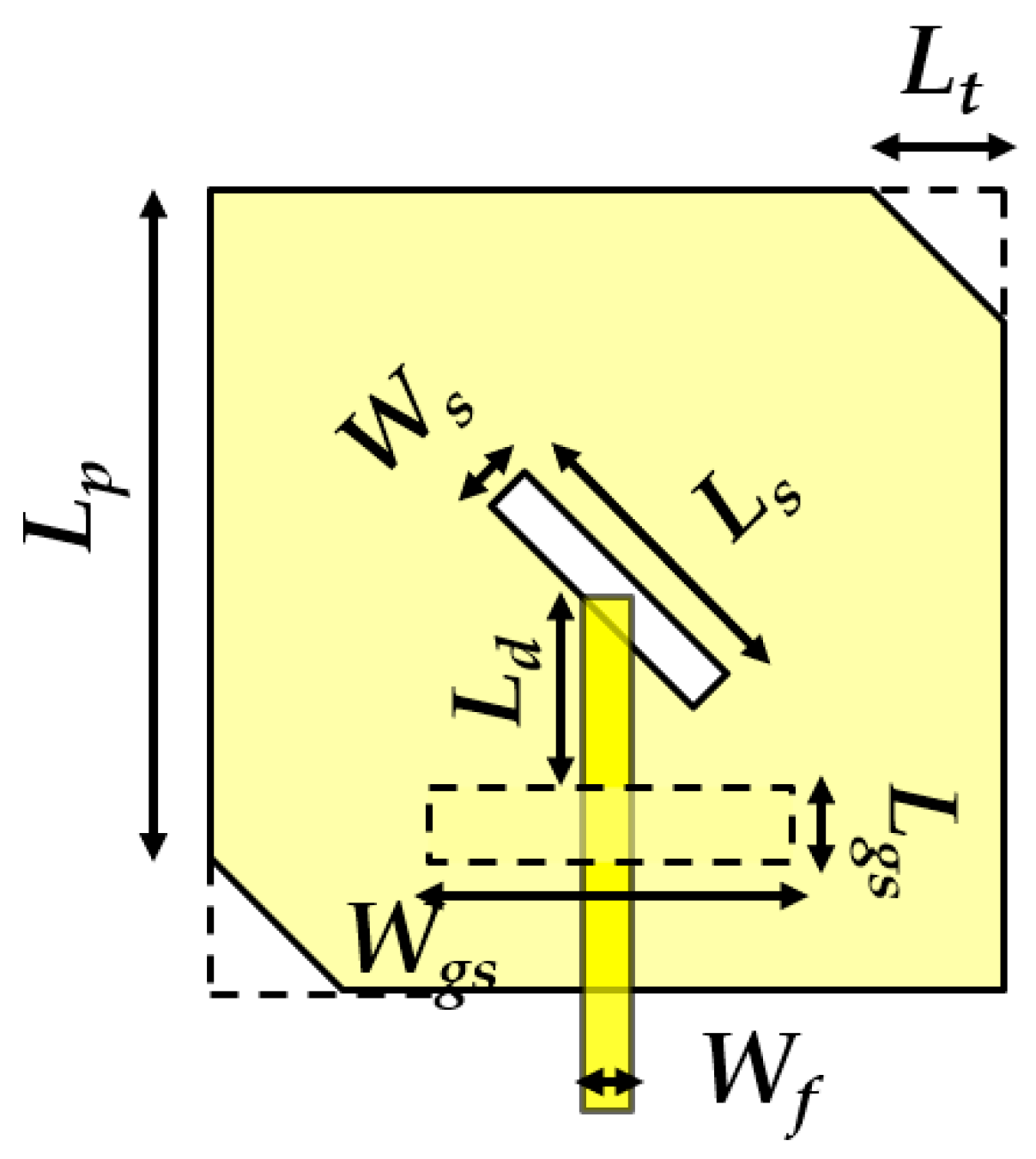
17]. The patch is excited via a rectangular slot placed in the ground, sandwiched between the two substrates. The maximum amount of power coupled from the rectangular slot to the patch element is determined by the higher-permittivity feed substrate and the positioning of the rectangular slot. The circular polarization was generated by introducing slots and cuts at 45° exciting two orthogonal modes with equal magnitude and 90° phase shift. The patch design offering an axial ratio AR < 3 dB at f = 3.5 GHz is shown in
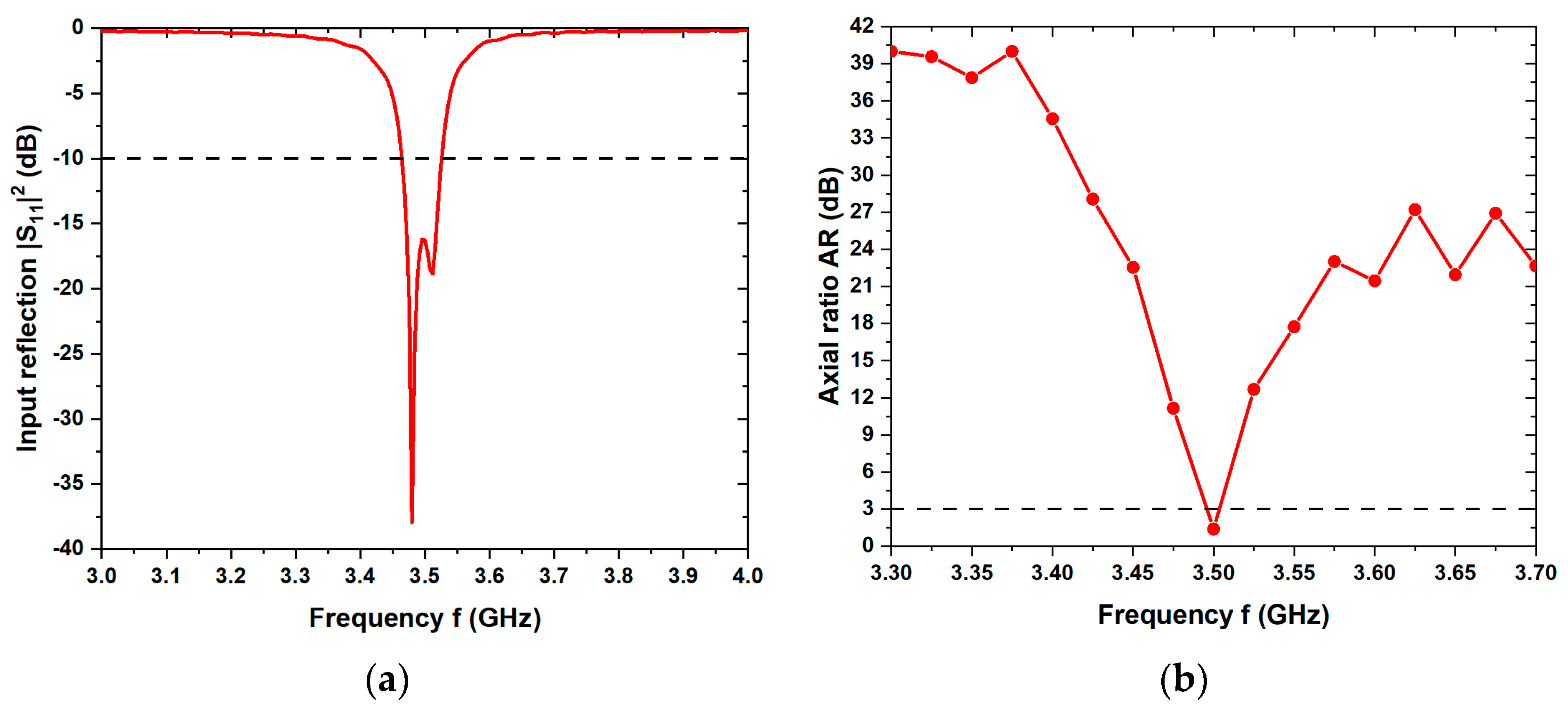
Figure 1. The proposed dimensions indicated in this figure were optimized with respect to the simulated -10 dB impedance bandwidth B
match = 62 MHz and the axial ratio AR = 1.4 dB at f = 3.5 GHz as can be seen in
Figure 2.
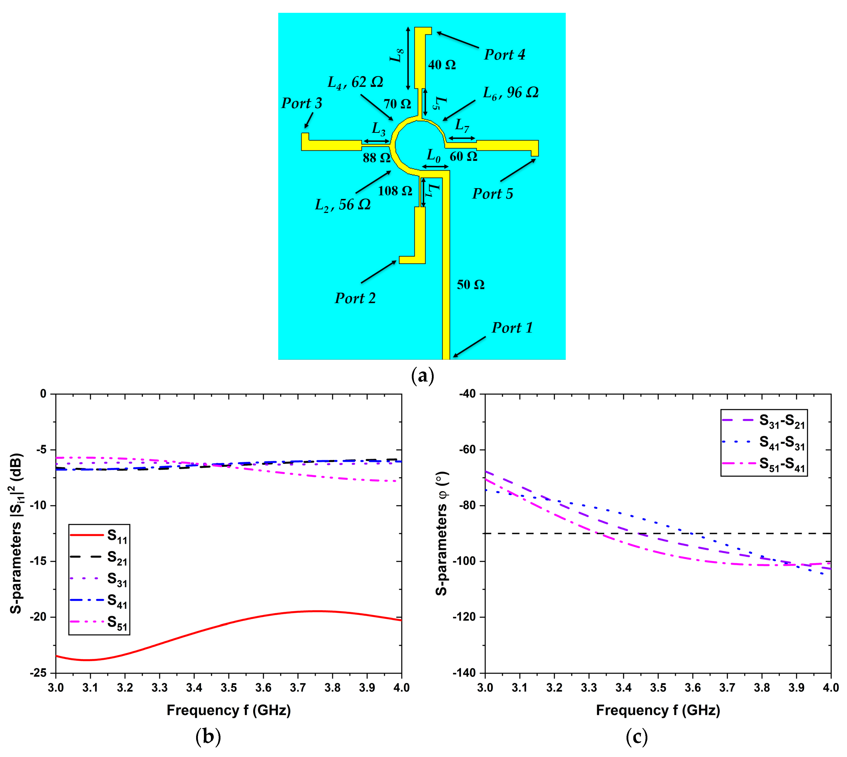
For the 2 × 2 CP antenna array, a sequentially rotated phase feeding configuration was employed as shown in
Figure 3 (a), in order to achieve a good CP performance across the desired frequency range. Port #1 marks the feed input, while ports #2 to #5 represent the power-balanced antenna feeds with incremental phase delay of 90°, connected to respective patch elements. The elements L
1 to L
7 represent quarter-wave impedance transformers in which L
2, L
4, and L
6 provide the impedance transformation between the junction points of the circular section of the phase feed.
Figure 3 (b) depicts the simulated S-parameters where the |S
11|
2 values stay well below -10 dB over the entire n78-band. Moreover, the optimal transmission parameters |S
i1|
2 (i = 2, 3, 4, 5) are close to -6 dB, ensuring that the input power is evenly distributed to each port.
Figure 3 (c) confirms the progressive phase difference of approximately 90° between the adjacent ports.
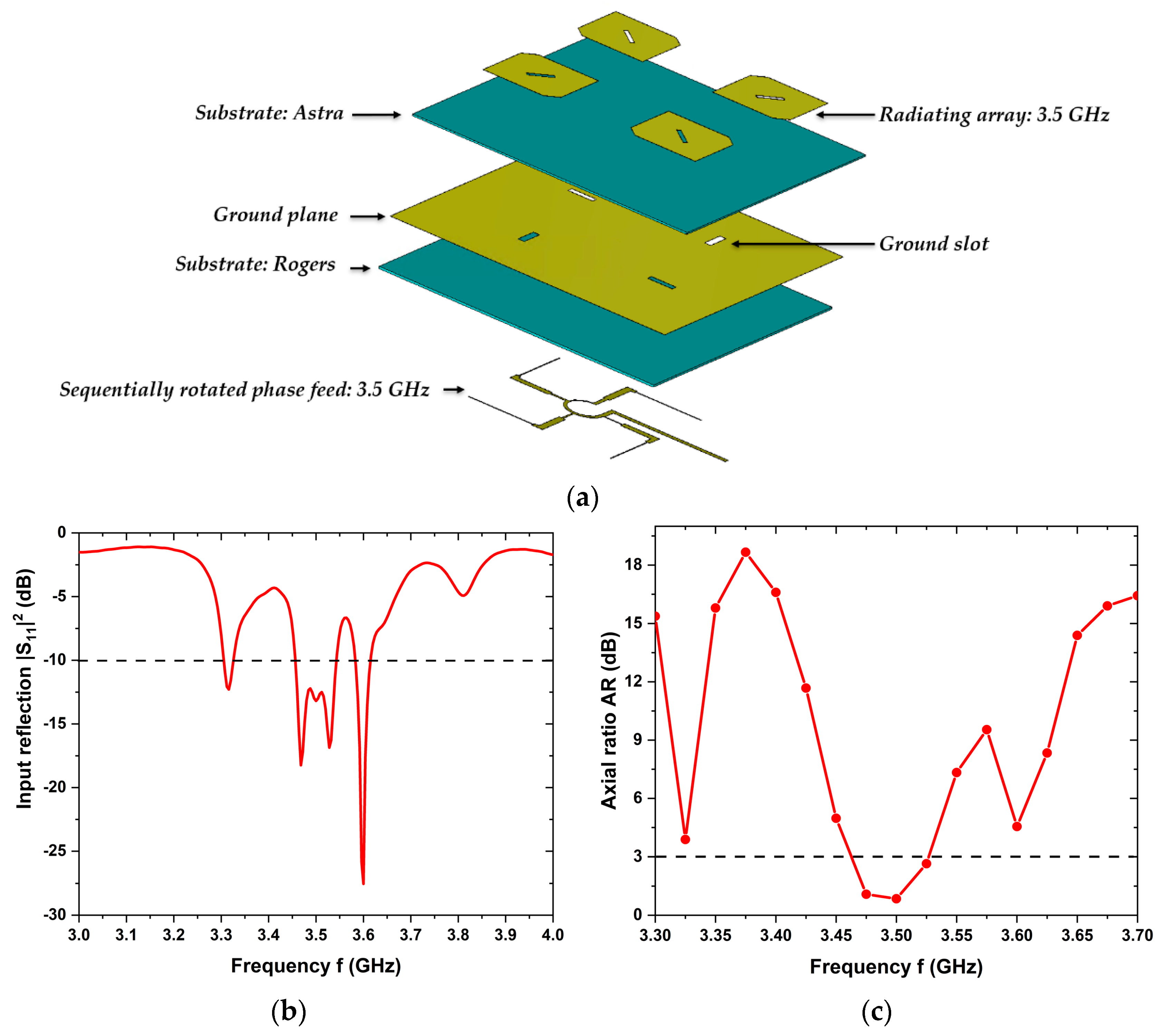
The single element was then extended to a low-profile, easy-to-integrate 2×2 aperture-coupled array as visualized in
Figure 4 (a). The radiating patch is placed on the Isola Astra® MT77 substrate and the phase feed is printed on the bottom of the Rogers RT 6010LM substrate. The rectangular coupling apertures from the feed to the patch elements are sandwiched between the two substrates. The distances between the horizontal and vertical individual elements were both adjusted to 0.5 λ
0 for minimum mutual coupling and side-lobe level, where λ
0 denotes the free-space wavelength. The simulated results reveal a -10 dB impedance bandwidth of B
match = 90 MHz and an axial ratio AR < 3 dB over a bandwidth of B
AR ≈ 65 MHz around f = 3.5 GHz as shown in
Figure 4 (b) and (c). The dimensions of the CP array including all design elements are listed in
Table 3.
3.2. Nested Antenna Arrays for 3.5 and 28 GHz
A compact single-layer 4×4 CP circular patch antenna array using a corporate feed network was proposed for the n257-band at the center frequency f = 28 GHz previously and its functionality demonstrated by measurements after embedding into the rear spoiler of a passenger car [
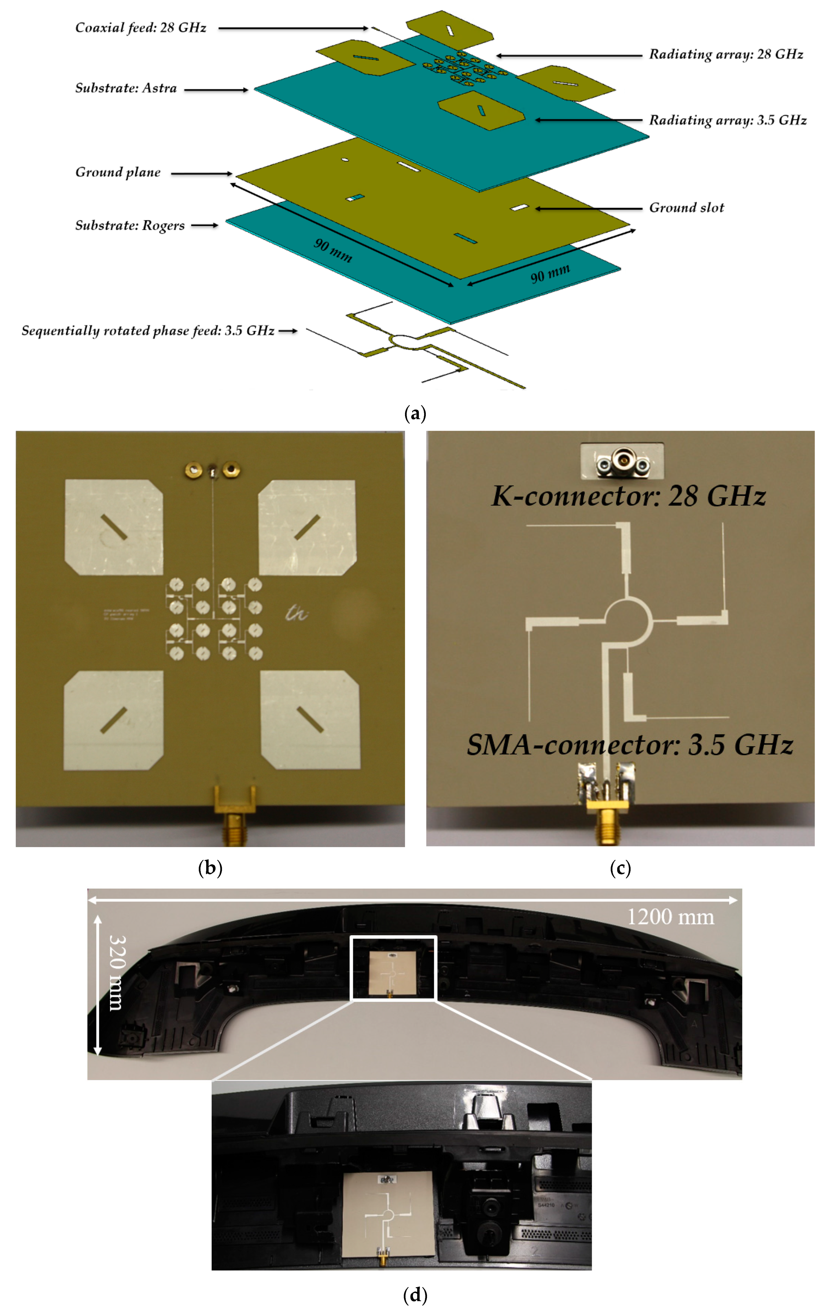
12]. This patch array was adopted to our proposed nested design and printed on an Isola Astra® MT77 substrate and arranged in the center of the 3.5 GHz array. The resulting dual-band nested array configuration is visualized in
Figure 5 (a). The separation between the horizontal and the vertical individual elements of the 2×2 array were both re-optimized to a value of 0.54 λ
0 so that the 28 GHz array maintains its rotational symmetry on the complete printed circuit board (PCB). The final nested array version is presented in
Figure 5 (b) and (c), with areal dimensions of 90 mm × 90 mm and a height of 1.25 mm. For the 28 GHz array, the center of the 50 Ω microstrip line contains through-holes to connect to a 2.92 mm K-connector from below. For the 3.5 GHz array, the center of the 50 Ω microstrip line is horizontally connected to a SMA connector. The dual-band nested array was embedded into a commercially available rear-spoiler of a passenger SUV (here: Ford Kuga as an exemplary version), as depicted in
Figure 5 (d), in order to study the influence of plastic embedding on the antenna performance. The front side is mounted in the plastic material acrylonitrile butadiene styrene (ABS) with a dielectric permittivity of ε
r = 2.88 and loss tangent of tan(δ) = 0.001 at 2 MHz [
18], covered with an acrylic lacquer (ε
r = 2.5, tan(δ) = 0.01 at 1 MHz) [
19], while the rear side remained exposed to ambient. This antenna arrangement is beneficial for pointing the main beam directly towards zenith for a longer period of time, in order to maintain the 5G VLEO link.
4. Simulation and Measurements Results
The bare version, i.e. facing ambient environment, dual-band nested patch array was designed using electromagnetic full-wave simulations, CST Studio Suite 2023 [
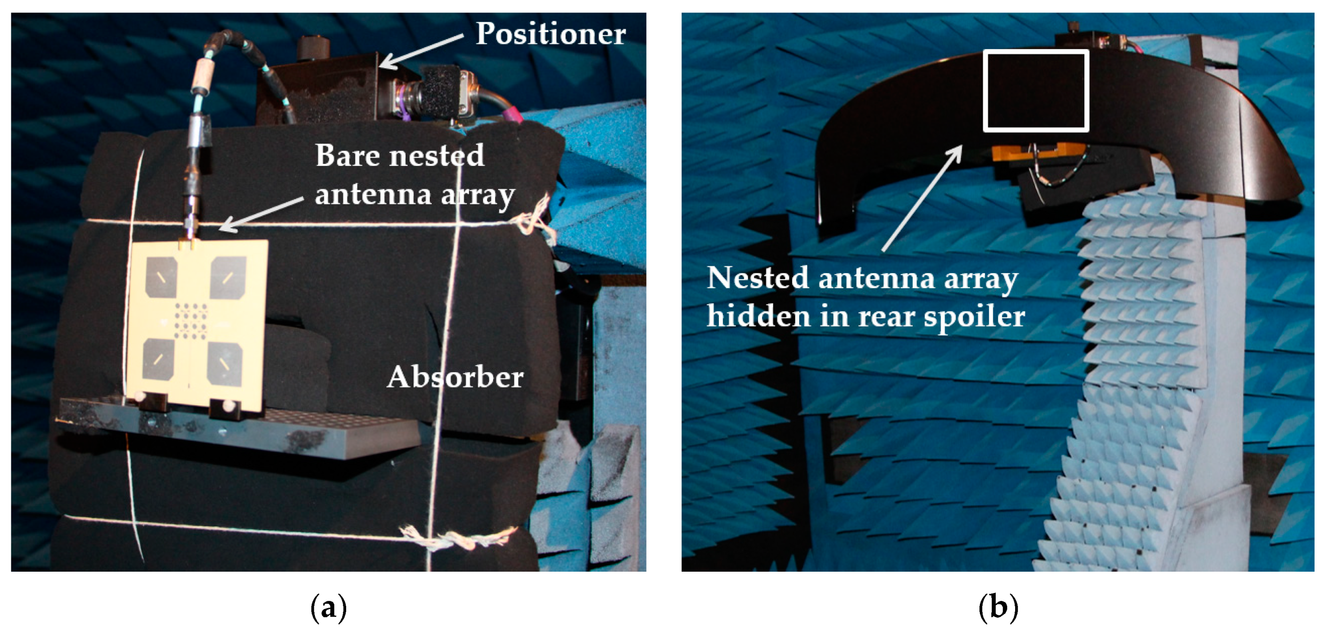
20]. Upon fabrication, measurements were carried out in a shielded anechoic chamber with ±1 dB measurement uncertainty across the frequency ranges of interest; a snapshot of the measurement setup is depicted in
Figure 6 (a). The array was mounted to a plastic holder and bolted to the rotating metallic positioner, covered with absorbing material to avoid unwanted artefacts in the measured radiation pattern. The array was then embedded into the rear spoiler and re-measured as shown in
Figure 6 (b). The nested array was designed and integrated such that it remains hidden in the rear spoiler.
4.1. Results for the 3.5 GHz array
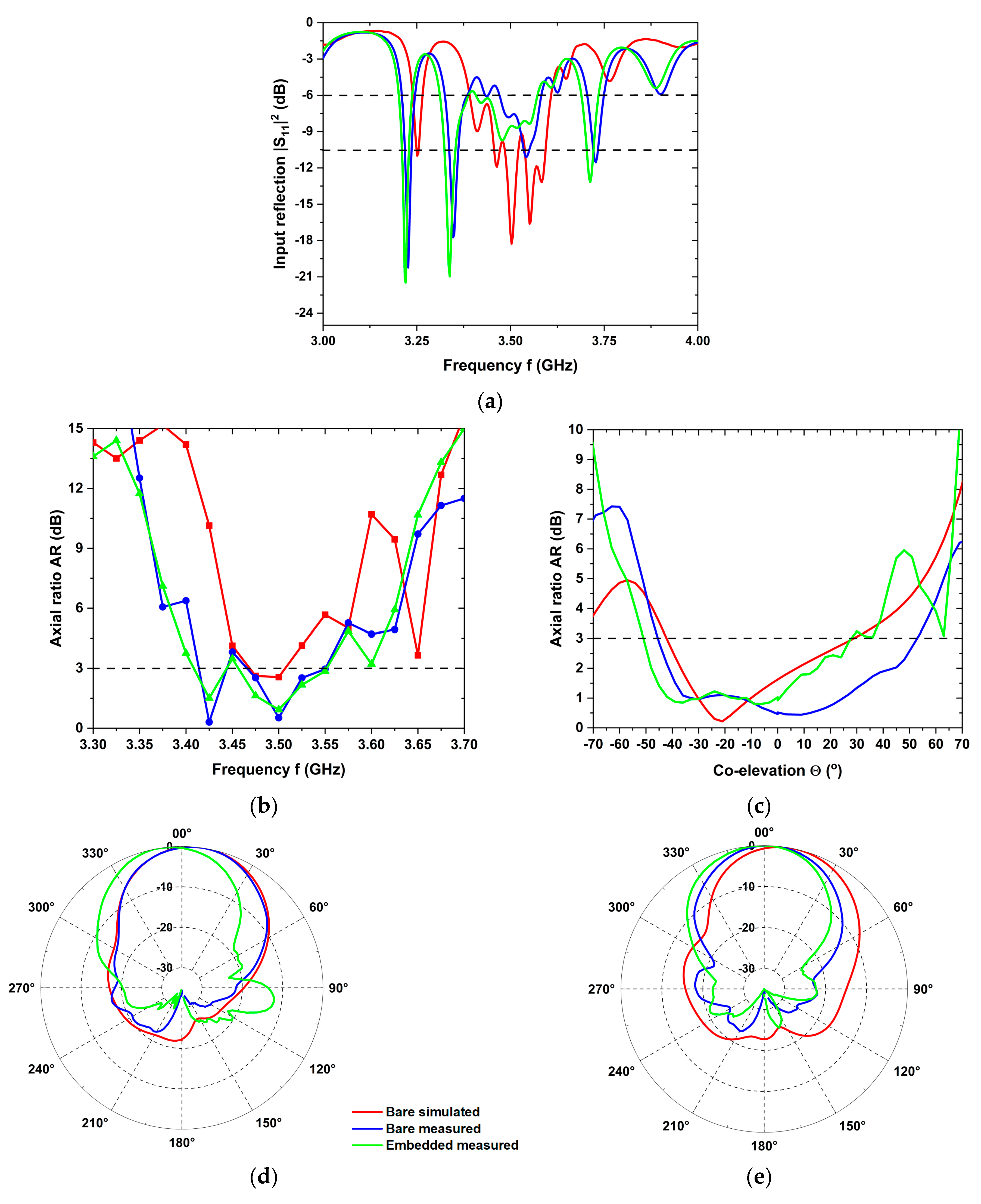
The impedance matching of the bare simulated (red curves), bare measured (blue), and embedded measured versions (green) across the entire n78-band is compared in
Figure 7 (a). The |S
11|
2 data for the embedded state follow the simulated trend but with smoothened ripple due to additional conductor losses. The operational bandwidth of Δf
op ≈ 100 MHz around f = 3.5 GHz is covered with a favourable input matching of |S
11|
2 < -10 dB for the bare simulated version, and while the matching level degraded to the still acceptable level |S
11|
2 < -6 dB for the bare measured version in the same bandwidth. The measurement in the embedded state covered |S
11|
2 < -6 dB over a bandwidth of 160 MHz, most likely reflecting the additional attenuation caused by the rear spoiler material.
The frequency variation of the axial ratio is shown in
Figure 7 (b), which confirms a favourable polarization symmetry with AR < 3 dB around f = 3.5 GHz for all three data sets. The embedded array exhibits a 3-dB axial ratio bandwidth B
AR ≈ 100 MHz. The angular variation of the axial ratio is shown in
Figure 7 (c), indicating an elevation range Θ from -40° to +30° where AR < 3 dB for the bare simulated version. These elevation ranges shifted for the measured bare and embedded versions to Θ = -45° … +50° and Θ = -50° … +25° respectively. All angular ranges cover the 3-dB beamwidth Θ
UE = ±30° of the proposed embedded array and appear feasible for the intended applications.
The simulated realized gain and the radiation efficiency of the array were found to be G
UEsim = 9 dBi and η
sim = 74 %, respectively. The radiation efficiency decreased slightly to η
meas = 59 % for the measurement of the bare antenna, associated with the reduced gain of G
UEmeas = 8.8 dBi. The radiation patterns are displayed in
Figure 7 (d) and (e) for the three versions. The normalized vertical cuts at Φ = 0° and 90° of the simulated and measured antenna in its bare state agree well with each other, while the pattern measured for the embedded array shifted towards 0° and a side lobe developed in the direction of excitation for Φ = 0°. Upon embedding, apparently, the plastic material covering the patch elements deteriorates the radiation performance of the antenna array, e.g., through degrading the symmetry and affecting the phase balance between the elements. In addition, the realized gain of the embedded array increased by 1 dB to G
emb = 9.9 dBi in comparison to the measured bare antenna array. The embedded array offers a 3-dB beamwidth of Θ
UE = -30°…+15° and an impedance bandwidth B
emb ≈ 160 MHz due to an increase in the overall thickness of the assembly.
All simulated and measured results are summarized in
Table 4. The data rate was calculated according to section 2. An uplink data rate of DR = 21 Mbit/s is anticipated for the embedded measured n78-band 2×2 square patch array, feasible for numerous wireless connected-vehicle applications.
4.2. Results for the 28 GHz array
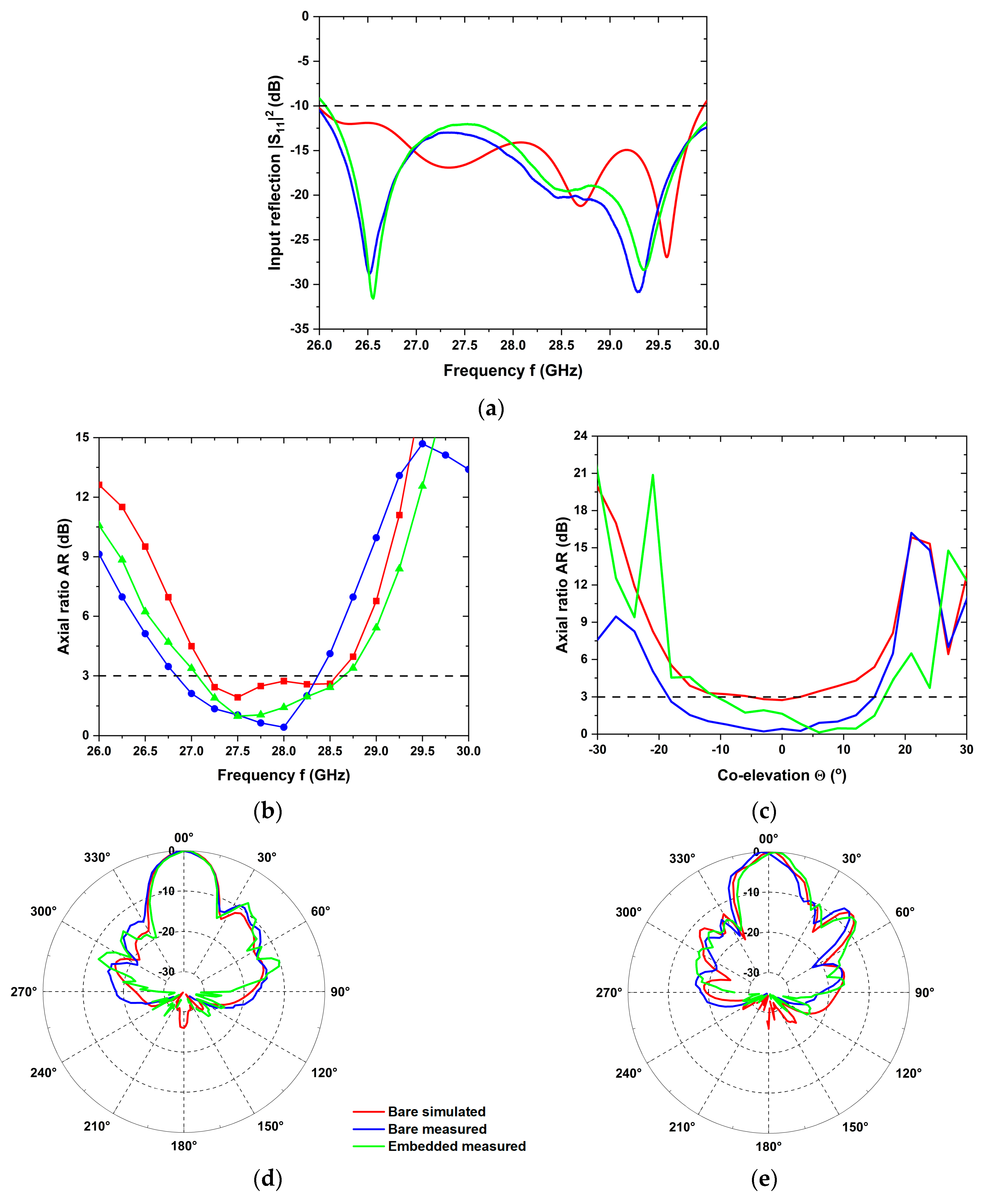
The impedance matching of the simulated and measured bare and embedded versions across the entire n257-band is depicted in
Figure 8 (a). The bare and embedded minimum |S
11|
2 values shifted slightly by 0.3 GHz to a lower frequency of 29.3 GHz compared to the simulations, while staying well below -10 dB. The manufactured array dimensions were measured with an optical profilometer with a measurement uncertainty below 1 m, revealing deviations of 2 % from the design parameters, which are considered negligible. The frequency shift, which is often observed in similar studies, is hence associated to variations of the dielectric permittivity. The back side of the embedded patch array remained exposed to the free space as depicted in
Figure 5 (d), and displayed almost the same resonant frequency as the bare version.
The frequency variation of the axial ratio is shown in
Figure 8 (b), achieving AR < 3 dB around f = 28 GHz for all three data sets. The embedded array exhibits a wide 3-dB axial ratio bandwidth B
AR ≈ 1500 MHz. The angular variation of the axial ratio is shown in
Figure 8 (c), indicating an elevation range from Θ = -18° … +15° with AR < 3 dB for the bare measured version, which slightly shifted to Θ = -11° … +17° for embedded version.
The simulated realized gain and radiation efficiency of the array amounted to G
UEsim = 15.4 dBi and η
sim = 85 %, respectively. The radiation efficiency decreased to η
meas = 60 % for the measured bare antenna, associated with a lower gain of G
UEmeas = 14 dBi. The radiation patterns are shown in
Figure 8 (d) and (e) for the three assembly versions. The normalized vertical cuts at Φ = 0° and 90° of the simulated and measured antenna in its bare state agree well with each other, while the pattern measured for the embedded array displays more pronounced ripples, in agreement with the findings for the lower frequency. In addition to the impact of dielectric embedding, adverse effects may result from the transition from the coaxial feed cable to the microstrip feed line. As a consequence, the realized gain of the embedded array decreased by 0.3 dB to G
emb = 13.7 dBi in comparison to the measured bare antenna array. The embedded array offers a 3-dB beamwidth of Θ
UE = ±12° and an impedance bandwidth B
emb > 4 GHz due to an increase of the overall thickness of the assembly.
All simulated and measured results are summarized in
Table 5. An uplink data rate of D
UL = 7 Mbit/s is anticipated for the measured free-space n257-band 4×4 circular patch antenna array. This value decreases to 6 Mbit/s for the embedded array due to the lower realized gain which, however, is still favourably suitable for the intended applications.
5. Conclusions
We demonstrated and verified through measurements after embedding into the rear spoiler of a passenger car a simple, cheap and easy-to-manufacture circularly polarized dual-band nested antenna array covering multiple 5G frequency bands-of-interest. Combining lower and higher spectral ranges foster scale effects across regions with decreasing network density - deploying next-generation mobile services to all regions worldwide. The nested UE antenna array meets promising performance figures for non-terrestrial 5G automotive applications. The n78-band exhibits a measured impedance bandwidth of 160 MHz with a 3-dB axial ratio bandwidth of 100 MHz, as embedded into the rear spoiler. An uplink data rate of 21 Mbit/s is anticipated from the peak realized gain of 9.9 dBi. At the Ka-band, the n257-band was covered with an impedance bandwidth of more than 4 GHz and with a 3-dB axial ratio bandwidth of 1500 MHz. The embedded array offered a peak realized gain of 13.7 dBi, from which an uplink data rate of 6 Mbit/s can be expected. The anticipated data rate values render numerous automotive wireless and internet-of-things applications feasible. As future work, we intend to design a common aperture antenna terminal for terrestrial and non-terrestrial 5G mobile communications covering multiple 5G bands, and to adjust the designs towards practical implementation and field testing.
Author Contributions
U.T., A.K., H.-P.P., M.E.A., and M.A.H., contributed to conceptualization, articulation, original draft preparation, review, and editing of the document. All authors have read and agreed to the published version of the manuscript.
Funding
The concept of automotive antennas embedded into plastic parts was developed with partial support from the Federal State of Thuringia, Germany, and the European Regional Development Fund (EFRE) under the grant 2015FE9042; the concept, design, and implementation of the NTN array has been funded by the German Space administration (DLR) under the grant 50 RK 2121.
Institutional Review Board Statement
Not applicable.
Informed Consent Statement
Not applicable.
Data Availability Statement
Not applicable.
Acknowledgments
We greatly acknowledge valuable contributions from Michael Huhn at TU Ilmenau, from Oliver Wick at BMW AG, from Mario Nowack GmbH and from Thomas Wack and Dr. Tristan Koppe at Wiegand GmbH.
Conflicts of Interest
The authors declare no conflict of interest. The funders had no role in the design of the study; in the collection, analyses or interpretation of data; in the writing of the manuscript or in the decision to publish the results.
References
- Fodor, G.; Vinogradova, J.; Hammarberg, P.; Nagalapur, K.K.; Qi, Z.T.; Do, H.; Blasco, R.; Baig, M.U. 5G New Radio for Automotive, Rail and Air Transport. IEEE Communications Magazine 2021, 59, 22–28. [Google Scholar] [CrossRef]
- Petry, H.-P. Die Chancen Innovativer Satellitenkommunikation in Einer Modernen Digitalisierten Gesellschaft. DeSK, Deutsches Zentrum für Satellitenkommunikation, Germany, 2019; pp. 1–119.
- Guidotti, A.; Vanelli-Coralli, A.; Conti, M.; Andrenacci, S.; Chatzinotas, S.; Maturo, N.; Evans, B.; Awoseyila, A.; Ugolini, A.; Foggi, T.; et al. Architectures and Key Technical Challenges for 5G Systems Incorporating Satellites. IEEE Trans Veh Technol 2019, 68, 2624–2639. [Google Scholar] [CrossRef]
- Kumar, A.; Petry, H.-P.; Tayyab, U.; Hein, M.A. Link Budget Considerations for Automotive 5G LEO Satellite-Based Communications. In Proceedings of the 2022 IEEE USNC-URSI Radio Science Meeting (Joint with AP-S Symposium); IEEE, July 10 2022; pp. 106–107.
- Boyle, A. (2016) A satellite antenna on your car: Toyota and Kymeta aim to make it so, GeekWire. Available at: https://www.geekwire.com/2016/a-satellite-antenna-on-your-car-toyota-and-kymeta-aim-to-make-it-so/ (Accessed: 27 September 2023).
- Geissler, M.; Woetzel, F.; Böttcher, M.; Korthoff, S.; Lauer, A.; Eube, M.; Wleklinski, M. Phased Array for Maritime Satcom Applications. In Proceedings of the 2011 German Microwave Conference; IEEE, March 14 2011; pp. 1–4.
- Tayyab, U.; Petry, H.-P.; Kumar, A.; Robbani, Md.G.; Wack, T.; Hein, M.A. Link Budget and Design Approach of a Non-Terrestrial 5G Automotive Antenna. In Proceedings of the 2022 52nd European Microwave Conference (EuMC); IEEE, September 27 2022; pp. 864–867.
- Singh, J.; Neumann, A.; Wack, T.; Koppe, T.; Stephan, R.; Hein, M.A. Novel Conformal Automotive Di-Patch Antenna Verified through Car Door Frame Measurements. In Proceedings of the Antennas and Propagation Conference 2019 (APC-2019); Institution of Engineering and Technology, 2019; pp. 1-5.
- Balanis, C.A. Antenna Theory: Analysis and Design, 4th ed.; John Wiley & Sons, 2016.
- Hall, P.S.; Dahele, J.S.; James, J.R. Design Principles of Sequentially Fed, Wide Bandwidth, Circularly Polarised Microstrip Antennas. IEE Proceedings H Microwaves, Antennas and Propagation 1989, 136, 381. [Google Scholar] [CrossRef]
- 3GPP. Base Station (BS) radio transmission and reception; Version 18.1.0; Technical Specification (TS) 38.104; 3rd Generation Partnership Project (3GPP), Valbonne, France, 2023.
- Tayyab, U.; Kumar, A.; Petry, H.-P.; Robbani, Md.G.; Wack, T.; Hein, M.A. Circularly Polarized Patch Antenna Array for 5G Automotive Satellite Communications. In Proceedings of the 2023 53rd European Microwave Conference (EuMC); IEEE, 2023, presented.
- Bluewalker 3. Available online: https://ast-science.com/spacemobile-network/bluewalker-3/ (accessed on 2 August 2023).
- C-V2X Use Cases and Service Level Requirements Volume II. Available online: https://5gaa.org/c-v2x-use-cases-and-service-level-requirements-volume-ii/ (accessed on 2 August 2023).
- Kedze, K.E.; Wang, H.; Park, I. A Metasurface-Based Wide-Bandwidth and High-Gain Circularly Polarized Patch Antenna. IEEE Trans Antennas Propag 2022, 70, 732–737. [Google Scholar] [CrossRef]
- Astra® MT77. Available online: https://www.isola-group.com/pcb-laminates-prepreg/astra-mt77-laminate-and-prepreg/ (accessed on 27 September 2023).
- Rt/duroid® 6006 and 6010.2LM Laminates. Available online: https://www.rogerscorp.com/advanced-electronics-solutions/rt-duroid-laminates/rt-duroid-6006-and-6010-2lm-laminates (accessed on 27 September 2023).
- PC-ABS - stratasys. Available at: https://go.stratasys.com/rs/533-LAV-099/images/MDS_FDM_PC-ABS_A4_0920a.pdf (Accessed: 27 September 2023).
- Technical data sheet APL acrylic protective lacquer. Available at: https://elektronik-lavpris.dk/files/sup2/044APL.pdf (Accessed: 27 September 2023).
- CST Studio Suite 3D EM Simulation and Analysis Software. Available online: https://www.3ds.com/products-services/simulia/products/cst-studio-suite/ (accessed on 27 September 2023).
Figure 1.
Single CP square patch antenna element. The geometrical dimensions detailed in
Table 3.
Figure 1.
Single CP square patch antenna element. The geometrical dimensions detailed in
Table 3.
Figure 2.
(a) Simulated frequency dependence of the input reflection coefficient |S11(f)|2, (b) simulated axial ratio AR(f) versus frequency.
Figure 2.
(a) Simulated frequency dependence of the input reflection coefficient |S11(f)|2, (b) simulated axial ratio AR(f) versus frequency.
Figure 3.
(a) Sequentially rotated phase feed network topology, (b) simulated S-parameters |Si1|2 (i = 1…5), (c) phase difference of signals between consecutive output ports.
Figure 3.
(a) Sequentially rotated phase feed network topology, (b) simulated S-parameters |Si1|2 (i = 1…5), (c) phase difference of signals between consecutive output ports.
Figure 4.
(a) Exploded view of the 2×2 bare patch antenna array (metallized layers in yellow, dielectric substrates in green), (b) simulated frequency dependence of the input reflection coefficient |S11(f)|2, (c) simulated axial ratio AR(f) versus frequency.
Figure 4.
(a) Exploded view of the 2×2 bare patch antenna array (metallized layers in yellow, dielectric substrates in green), (b) simulated frequency dependence of the input reflection coefficient |S11(f)|2, (c) simulated axial ratio AR(f) versus frequency.
Figure 5.
(a) Exploded view of the proposed dual-band nested antenna array, (b) optical photograph of the manufactured version: Top view, (c): Bottom view, (d) version embedded into the rear spoiler of a passenger vehicle with magnified view of the array PCB.
Figure 5.
(a) Exploded view of the proposed dual-band nested antenna array, (b) optical photograph of the manufactured version: Top view, (c): Bottom view, (d) version embedded into the rear spoiler of a passenger vehicle with magnified view of the array PCB.
Figure 6.
(a) Antenna measurement setup in bare condition, (b) measurement setup in rear spoiler.
Figure 6.
(a) Antenna measurement setup in bare condition, (b) measurement setup in rear spoiler.
Figure 7.
(a) Input reflection coefficients |S11|2 for the bare simulated (red-colored curve), bare measured (blue) and embedded measured (green) antenna array, (b) axial ratio versus frequency along zenith, Θ = 0°, (e) axial ratio versus co-elevation at f = 3.5 GHz, (d) vertical cut of normalized realized gain at f= 3.5 GHz for Φ = 0° and (e) for Φ = 90° (same color coding as in panel a).
Figure 8.
(a) Input reflection coefficients |S11|2 for the bare simulated (red-colored curve), bare measured (blue), and embedded measured (green) antenna array, (b) axial ratio versus frequency along zenith, Θ = 0°, (e) axial ratio versus co-elevation at f = 28 GHz, (d) vertical cut of normalized realized gain at f= 28 GHz for Φ = 0° and (e) for Φ = 90° (same color coding as in panel a).
Table 1.
Link budget parameters for the n78-band in the uplink.
Table 1.
Link budget parameters for the n78-band in the uplink.
| Parameter |
Symbol |
Value |
Unit |
| Orbital height |
d |
400 |
km |
| Center frequency |
f |
3.5 |
GHz |
| 3-dB beamwidth of satellite |
Θsat
|
2 |
° |
| Radius of coverage area |
R |
7 |
km |
| Satellite antenna edge gain |
Gsat
|
38.3 |
dBi |
| Free-space path loss |
αFS
|
156 |
dB |
| UE output power |
PTX UE
|
32 |
dBm |
| UE antenna gain |
GUE
|
10 |
dBi |
| UE EIRP |
EIRPUE
|
42 |
dBm |
| Atmospheric loss |
αatm
|
3.5 |
dB |
| Power level at satellite |
PRXsat
|
-117 |
dBm |
| Satellite noise figure |
NFsat
|
3 |
dB |
| Signal bandwidth |
Bsig
|
5 |
MHz |
| SNR at demodulator |
SNRUL
|
24.2 |
dB |
| Spectral efficiency |
SE |
4.15 |
bits/s/Hz |
| Data rate |
DRUL
|
21 |
Mbit/s |
Table 2.
UE antenna performance requirements.
Table 2.
UE antenna performance requirements.
| Parameter |
NTN |
Unit |
| Frequency band Δf |
n78 (3.3…3.8) |
n257 (26.5…29.5) |
GHz |
| Frequency f |
3.5 |
28 |
GHz |
| Operational bandwidth Bop
|
100 |
400 |
MHz |
| Polarization purity |
AR < 3 |
dB |
| Co-elevation coverage ΘUE |
-30…+30 |
° |
| Azimuth coverage ΦUE
|
0…360 |
° |
Table 3.
Geometrical dimensions of the 2 × 2 patch antenna array.
Table 3.
Geometrical dimensions of the 2 × 2 patch antenna array.
| Design element |
Symbol |
Detail |
Dimension (mm) |
Impedance (Ω) |
| Patch |
Lp
|
Length |
19.3 |
|
| Truncated corner |
Lt
|
Length |
4 |
| Slot |
Ls
|
Length |
8 |
| Ws
|
Width |
1.5 |
| Ground slot |
Lgs
|
Length |
2 |
| Wgs
|
Width |
8 |
| Feed to ground slot |
Ld
|
Length |
5 |
| Wf
|
Width |
0.5 |
| 50 Ω microstrip line |
Lo
|
Length |
6 |
| Width |
1.5 |
| Quarter-wave transformers |
L1 |
Length |
5.8 |
108 |
| Width |
0.3 |
| L2
|
Length |
8.5 |
56 |
| Width |
1.2 |
| L3
|
Length |
5.7 |
88 |
| Width |
0.5 |
| L4
|
Length |
8 |
62 |
| Width |
1 |
| L5
|
Length |
6 |
70 |
| Width |
0.8 |
| L6
|
Length |
7 |
96 |
| Width |
0.4 |
| L7
|
Length |
5.9 |
60 |
| Width |
1.1 |
| L8
|
Length |
12 |
40 |
| |
Width |
2 |
Table 4.
Summary of simulated and measured results of bare and embedded patch array.
Table 4.
Summary of simulated and measured results of bare and embedded patch array.
| Parameter |
Bare antenna |
Embedded antenna |
| simulated |
measured |
measured |
| Input reflection |S11|2 (dB) |
-18 |
-11 |
-9 |
| Realized gain G (dBi) |
9 |
8.9 |
9.9 |
| 6-dB bandwidth B-6 (GHz) |
210 |
110 |
160 |
| Radiation efficiency η (%) |
74 |
59 |
67 |
| 3-dB axial ratio bandwidth BAR (GHz) |
30 |
80 |
100 |
Table 5.
Summary of simulated and measured results of bare and embedded patch array.
Table 5.
Summary of simulated and measured results of bare and embedded patch array.
| Parameter |
Bare antenna |
Embedded antenna |
| simulated |
measured |
measured |
| Input reflection |S11|2 (dB) |
-14 |
-16 |
-14.5 |
| Realized gain G (dBi) |
15.4 |
14 |
13.7 |
| 10-dB bandwidth B-10 (GHz) |
4 |
> 4 |
> 4 |
| Radiation efficiency η (%) |
85 |
60 |
56 |
| 3-dB axial ratio bandwidth BAR (GHz) |
1300 |
1525 |
1500 |
|
Disclaimer/Publisher’s Note: The statements, opinions and data contained in all publications are solely those of the individual author(s) and contributor(s) and not of MDPI and/or the editor(s). MDPI and/or the editor(s) disclaim responsibility for any injury to people or property resulting from any ideas, methods, instructions or products referred to in the content. |
© 2023 by the authors. Licensee MDPI, Basel, Switzerland. This article is an open access article distributed under the terms and conditions of the Creative Commons Attribution (CC BY) license (http://creativecommons.org/licenses/by/4.0/).
