1. Introduction
Graphite based carbonaceous materials are gaining more and more of importance since their use within different industrial field is expanding. Depending on its state, natural or artificial, the use of graphite varies from moulds fabrication used in high purity materials pouring (e.g. SiO
2) [
1] to atomic energy field (cooling part of the reactors) [
2].
Graphite is formed by parallel carbon sheets having sp
2 rhomboidal bonds and each atom is in close contact with its neighbouring atoms. Each sheet is formed by a series of continuous hexagons of which each carbon atom ins connected with other three. The bonds are covalent (sigma bonds) having a short length (0.141 nm) and high strength (524 kJ/kmol) [
3].
The fourth electron is hybridized forming a Van der Waals (π bond) bond with another electron from neighbouring sheet. The distance between the sheets is relatively large (0.335 nm) meaning more than double of the bond length of the atoms within the same sheet [
4].
Natural graphite based materials can be used in different fields but they must fulfil some specific conditions, such as inorganic substances content below 30 ppm, extremely low porosity and low thermal dilatation coefficient. [
5,
6,
7]
On the other hand, synthetic graphite and synthetic graphite based materials can be tailored to fit the exact requirements of the field they are used in.
Several papers were focused on manufacturing, characterization and improvement of synthetic graphite based materials in the field of nuclear industry [
8,
9,
10]. Thus, the graphite used for such applications must meet very specific demands as for synthetic graphite based materials used for cooling the reactors where fast travelling neutrons resulting from the collide of uranium atoms with slow neutrons must be slowed down without neutron loss. In this case, the elastic collides between fast neutrons and graphite ensure that this requirement is met resulting less radiation and a safer environment. The technology used to prepare graphite used in this applications is tailor made and the resulting graphite is called "high density graphite".
Other papers are focused on synthetic graphite based materials used for batteries electrodes, mainly anodes [
11,
12,
13]. For this kind of applications, synthetic graphite based materials must be prepared from natural graphite and mesophase pitch heated together until melting. Those materials must meet both mechanical and electrical properties requested by high currents flowing inside the battery.
There are other types of synthetic graphite based materials that are used in different fields such as dynamic sealing where flexible graphite is currently used, protective covers and insulation materials able to protect vacuum chambers from impurities diffusion, etc. [
15,
16].
Among few of the most important characteristics that synthetic graphite based materials must meet are material density and porosity. Even though papers such [
17,
18,
19,
20] which tackled the issue of material density and papers such as [
21,
22,
23,
24,
25] tackled ways to obtain very low material porosity the maximum potential of such type of materials (high density graphite based materials) is still to be assessed.
Current paper is aiming to investigate an innovative technique for obtaining high density - low porosity graphite in one go. Moreover, by obtaining own mesophase tar pitch and using it to decrease material porosity instead of currently industrial use of molten metal, the obtained technique is more environmentally friendly and uses low energy since mesophase tar pitch needs to be heated just until 470°C, unlike molten metal that often reach ~1000°C. So, within this paper two types of materials have been obtained: mesophase tar pitch from tar and high density-low porosity graphite. High density graphite was obtained by impregnating different types of graphite with mesophase tar pitch.
2. Materials and Methods
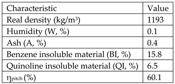
Raw materials used for obtaining the mesophase pitch was crude tar from Donasid Calarasi-Romania having the following characteristics:
Raw materials for obtaining high density graphite are:
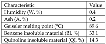
Type E impregnation pitch from ISPAT_SIDEX Galati-Romania having the following characteristics:
Coloidal natural graphite from ICSI Ramnicu Valcea-Roamnia

Burnt petroleum coke, 3 types from: PETROBRAZI refinery-Petrom Romania, PETROMIDIA refinery-Rompetrol Romania, Shell refinery-Germany having the following characteristics:

All the above mentioned characteristics have been determined within the lab and are described as follows:
2.1. Real density determination
Real density represents the density of a material excluding its pores and can be calculated as ratio between material's mass and its volume. The unit can be kg/m3 or g/cm3.
Real density of porous materials was determined by using picnometer method. Thus empty, clean and dried of known volume picnometer having their caps and thermometers attached have been weighted on analytical balance having a precision of 0.0001g.
Then, the picnometer placed in a themal bath set at 20°C was filled in with methanol RA 99.9% purity, from WWR Chemicals-Germany and weighted again thus resulting the mass of the methanol. By knowing the mass of the methanol and the volume of the picnometer, the real density of the methanol has been calculated.
I order to determine the real density of the sample, 1g of porous material has been placed inside the picnometer. After that, the picnometer was filled in with methanol and kept at 20°C. Then, the picnometer was connected to a vacuum pump and kept under vacuum until no air bubbles were formed. It is to be mentioned that air bubbles are forming while the air from material's pores is released. After that, the vacuum was released allowing methanol to fill in the pores of the material. As expected, the level of methanol within the picnometer decreased. The picnometer was again filled in with methanol and the volume represents the pore volume.
Real density of the material was calculated as a ratio between its mass and volume (minus the pore's volume).
2.2. Humidity determination
In order to determine the sample's humidity (Wha), ~1 g of sample has been weighted and put in an uncovered vial. Then the vial was placed in a 105°C heated furnace and the temperature was kept constant for 1 hour. After that, the vial was covered (in order not to let air moisture of get to the sample), cooled at room temperature and then weighted again.
2.3. Volatiles determination
Volatiles (Va) are representing the total amount of eliminated substances (except humidity) during heating of a material.
Firstly, 0.0001 precision material mass (~1 g) was placed in a quartz crucible, lid was put on and was weighted. After that, the crucible was heated in a furnace at 850°C for 7 minutes. Then the crucible was taken out and let to cool at room temperature then weighted again.
%V
a was calculated according to the equation:
where: m
1 - mass of empty crucible, lid on (g), m
2 - mass of crucible containing sample, lid on before heating (g), m
3 - mass of crucible containing sample, lid on after heating (g), W
ha - sample humidity (%).
2.4. Ash determination
Ash is the solid residue obtained after the sample is burnt at 815˚C until the remaining mass is constant. Its symbol is “A” and represents the ratio between the residual mass and initial mass of the sample.
1 gram of sample having the particle dimension of 0.2 mm has been weighted and put in a ceramic crucible. The crucible was put in a furnace at room temperature and then the heat was turned on until it reached 815˚C within 60 minutes. The slow heating is necessary in order to avoid material or ash particles to be eliminated along with the volatiles. After the temperature was reached, it was kept for 30 minutes to allow the entire sample to burn. Then the crucible was kept in a humidity free vessel and weighted.
Resulting ash was calculated by using the following equation (2):
where: m
1 - mass of empty crucible, m
2–mass of crucible and sample, m
3 – mass of the crucible and solid residue after burning.
2.5. Method for obtaining mesophase pitch
In order to obtain the mesophase pitch, crude tar from DonasidCalarsi was used. Ths was mixed with toluene 1:1 Ratio and heated up to 60˚C then filtered while hot. By using this method the materials insoluble in toluene were separated from the tar. After distillation when the toluene was removed, the resulting material is purified tar.
All the above described analyses were performed for the obtained purified tar.
The second step was to distil the tar until 340˚C and the residue is a pitch resulted from the purified tar. Again, all the analyses were performed.
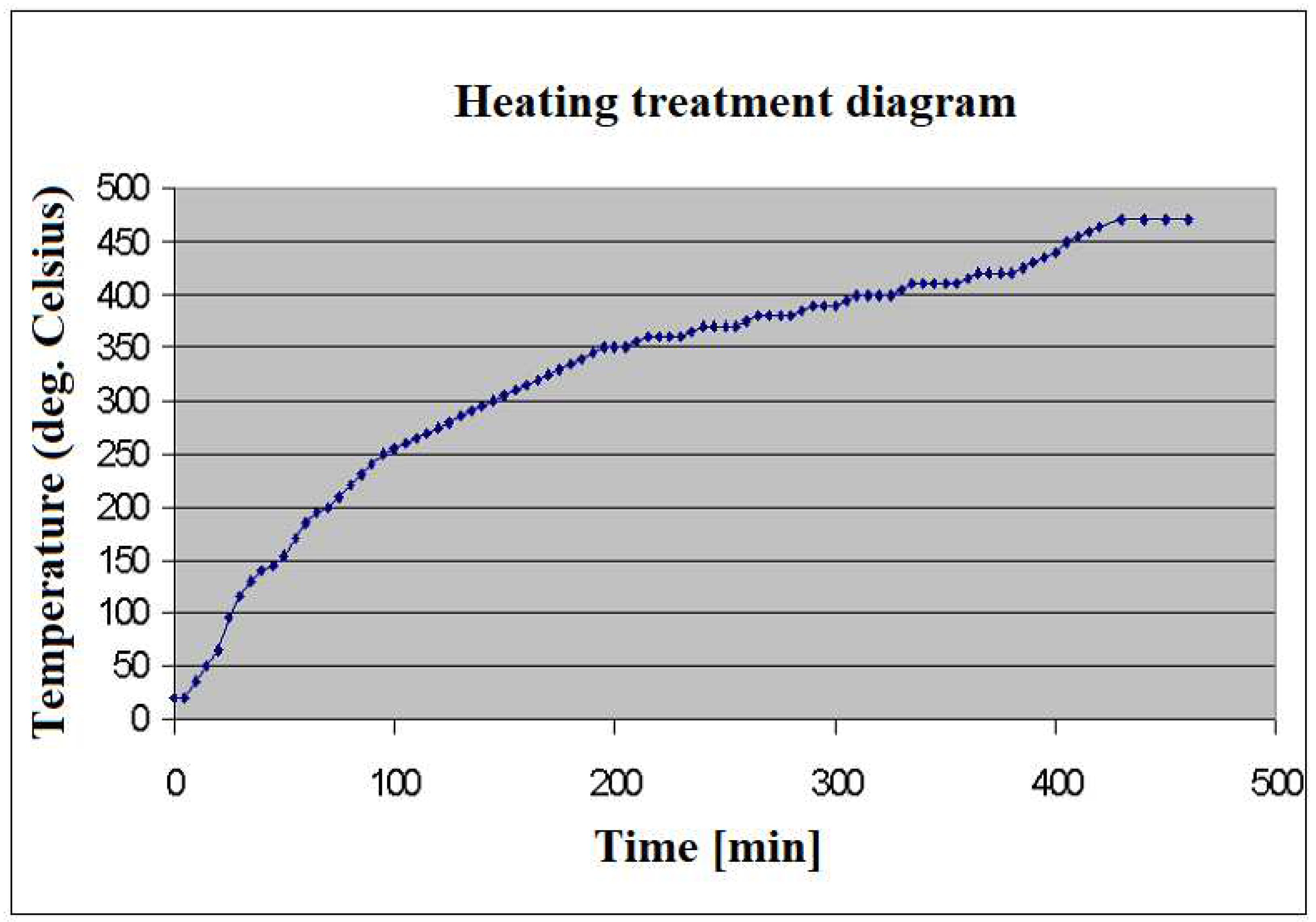
In order to obtain the mesophase pitch, the tar pitch was thermally treated as follows: from room temperature until 100˚C wth a heating speed of 5˚C/min, from 100 to 250˚C with a heating speed of 3˚C/min and from 250 to 470˚C with a heating speed of 1˚C/min. Then the 470˚C was kept for 20 minutes.
Mesophase pitch was obtained at an yield of 45% and the heating treatment diagram is shown in
Figure 1.
The obtained pitch was milled until 0.25 mm.
2.6. Method for obtaining of high density graphite
High density graphite was obtained by mixing the pitches described above (acting as binder) and fillers represented by cokes and graphite described within raw material section.
All the obtained mixtures were thermally treated 2 times: firstly the carbonization treatment and secondly the graphitization treatment.
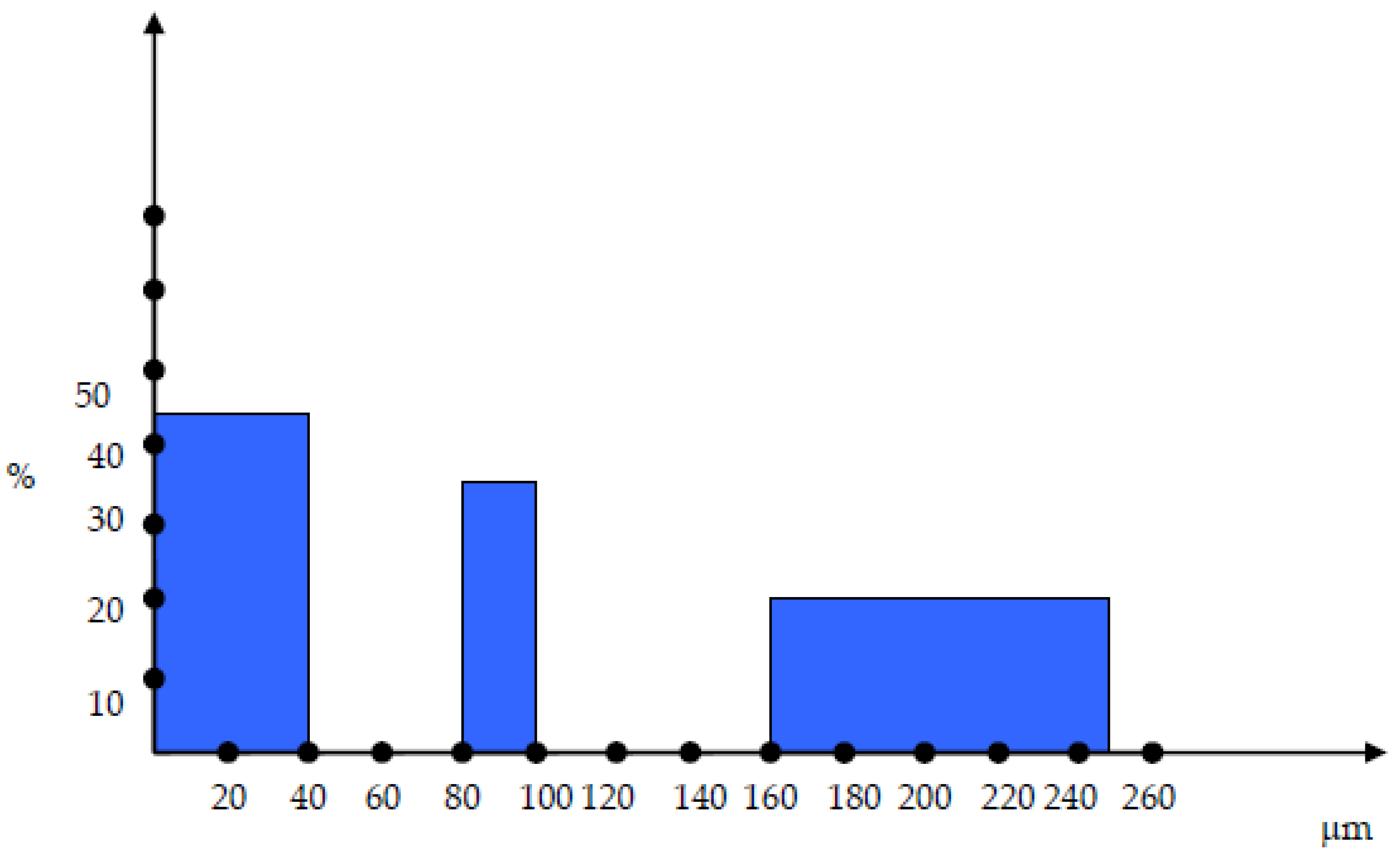
The cokes were sorted in 3 different particle dimensions: 0-40 µm, 80-100 µm and 160-250 µm as shown in
Figure 2.
The mixtures have been configured as follows: 160-250 µm – 20%, 80-100 µm – 35%, 0-40 µm – 45%.
As it can be seen in figure 2, there are two discontinuities within the particle size distribution and those discontinuitites have been chosen in order to ensure the maximum compactation of the material and minimum gaps.
The binder (above described pitches) was 20% wt. compared with the filler.
The samples have been obtained by mixing different binders and filles as folows:
Sample 1: Natural graphite + Type E impregnation pitch
Sample 2: Petroleul coke from PETROBRAZI + Type E impregnation pitch
Sample 3: Petroleul coke from PETROMIDIA + Type E impregnation pitch
Sample 4: Petroleul coke from SHELL + Type E impregnation pitch
Sample 5: Natural graphite + mesophase pitch
Sample 6: Petroleul coke from PETROBRAZI + mesophase pitch
Sample 7: Petroleul coke from PETROMIDIA + mesophase pitch
Sample 7: Petroleul coke from SHELL + mesophase pitch
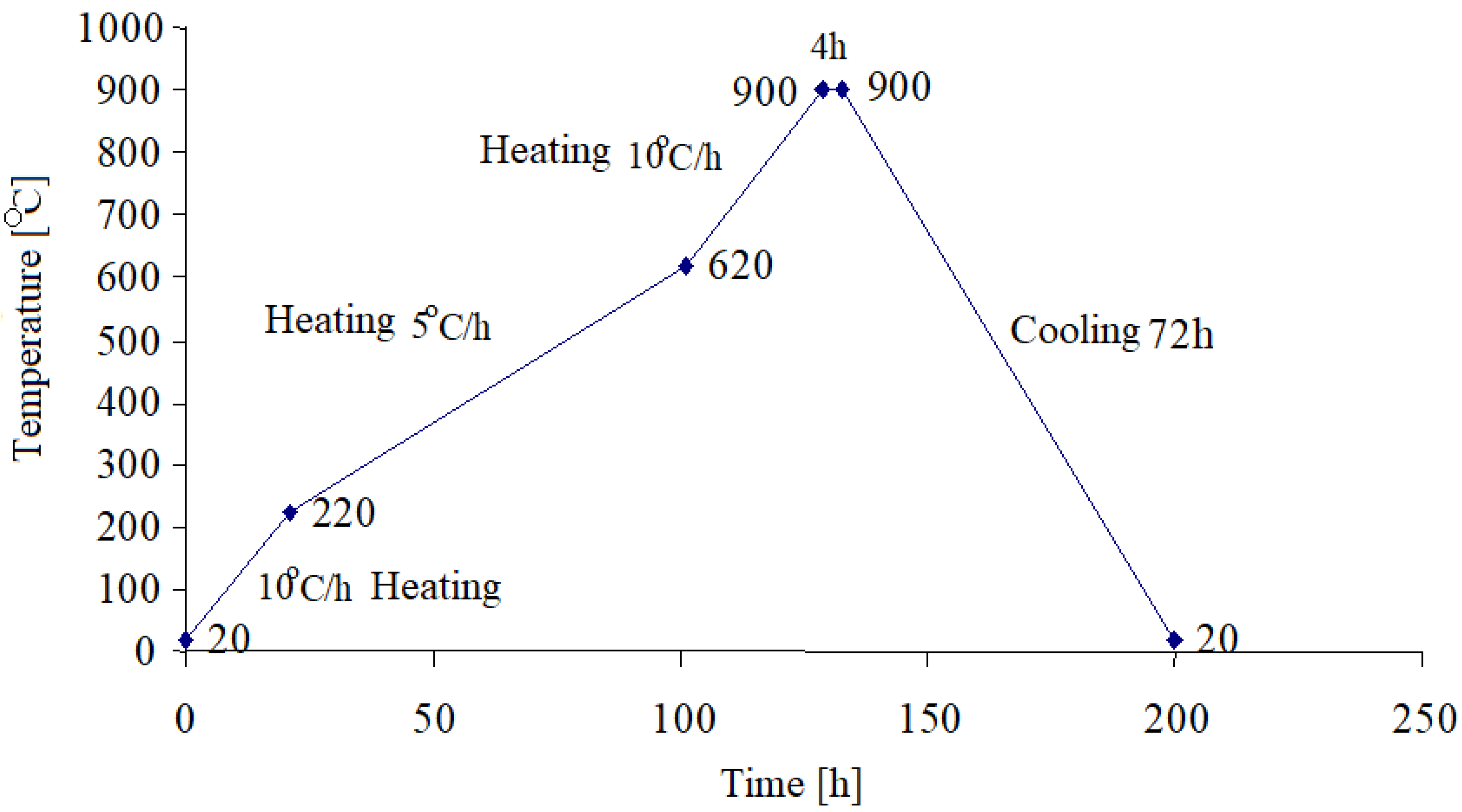
The obtained samples were mixxed, homogenized and then pressed at 600 kgf/cm
2 follwed by the carbonization thermal treatment, in the absence of air and according to the heating diagram as shown in
Figure 3.
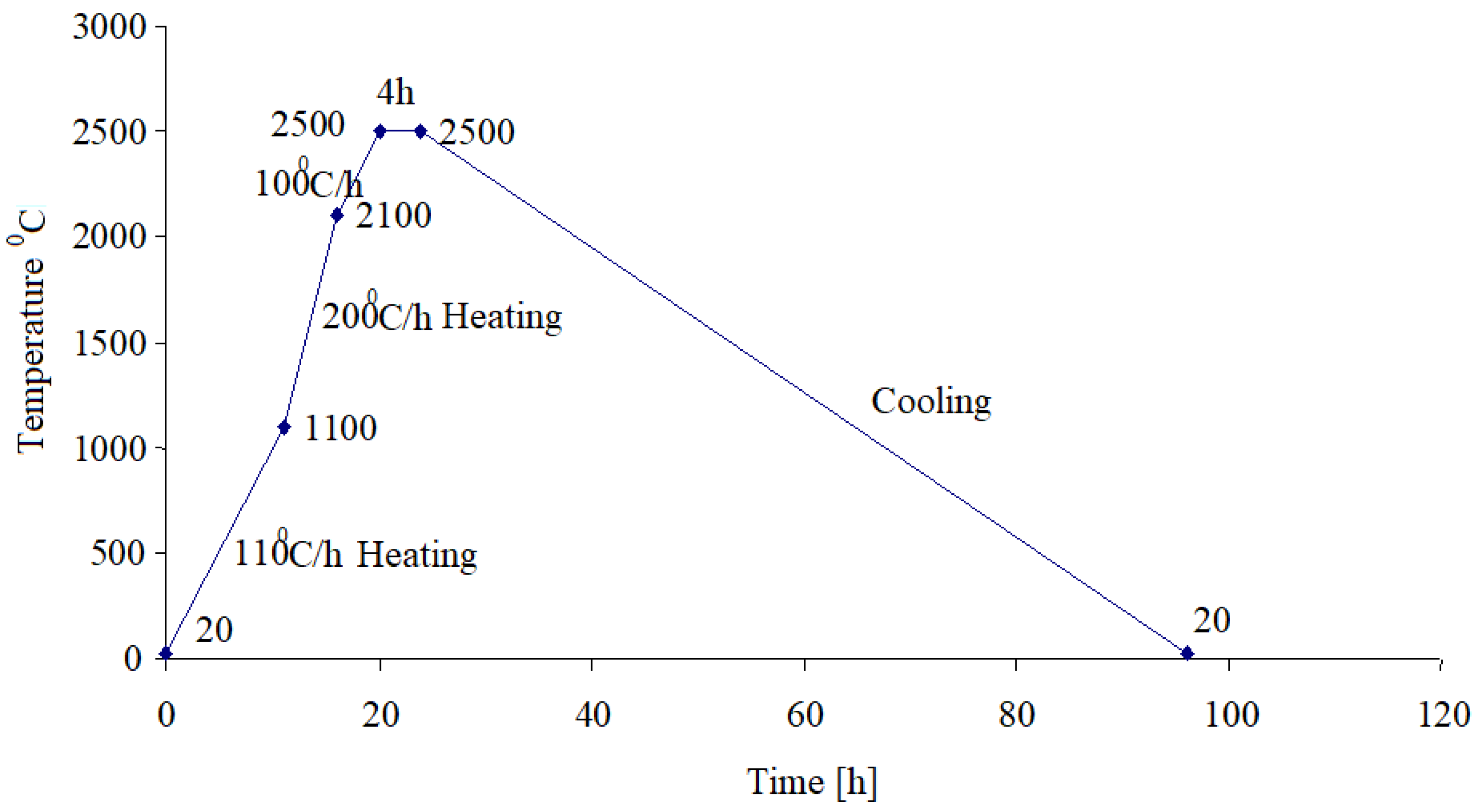
After the carbonization treatment, the samples were subject to the graphitization process which happens at high temperatures as the heating diagram shown in
Figure 4 is showing.
3. Results and Discussion
After all the needed raw materials and samples were obtained and characterized as described in section 3, these are the results:
The comparison between the characteristics of crude and purified tar are shown in table 5
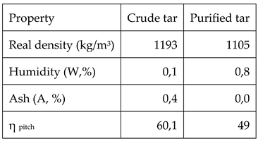
As it can be observed in table 5, the real density of the tar decreases after purification due to the fact that all the large molecular mass components, existing ash and coke like particles have been removed after filtration. As o consequence, ash content is practically zero. Moreover, the fact that large molecular mass components have been removed decreases the yield of pitch production.
Table 6 is showing the characteristics of the pitches obtained from crude tar: purified tar pitch and mesophase pitch.
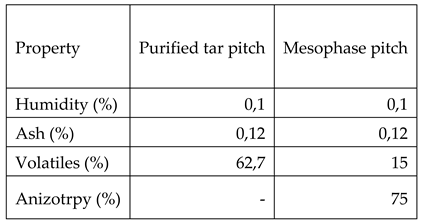
As it can be observed by comparing the data from table 2 with the ones in table 6, type E pitch which is commonly used for obtaining graphitic materials has an increased humidity and ash compared both with purified tar pitch (the precursor for mesophase pitch) and obtained mesophase pitch. Also mesophase pitch shows 75% anisotropy, compared with the other two pitches (type E and purified tar) which are 100% isotropic pitches. Also mesophase pitch has lower volatiles content.
By analyzing the obtained samples after the graphitization process it clearly emerge that apparent and real density are the most important parameters to be taken into account when high density graphite is obtained. Another two important characteristics are compression resistance and porosity of the material.
Therefore, the above mentioned characteristics are shown in table 7
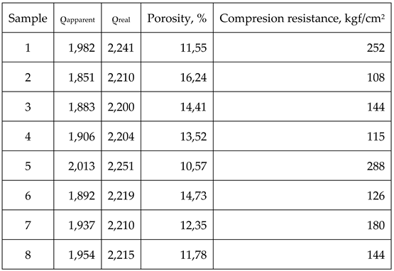
By analysing the data within table 7 clear differences between samples 1-4 produced by using type E impregnation pitch and samples 5-8 obtained by using mesophase pitch can be assessed, as such:
- -
Samples 5-8 obtained by using mesophase pitch show higher density than samples 1-4 obtained by using type E impregnation pitch. The variation is consistent throughout the group, meaning that differences between samples 1-5, 2-6, 3-7 and 4-8 are exclusively due to the binding material.
- -
The porosity is also lower for the group 5-8 compared to group 1-4 also due to the binding material. Mesophase pitch has a lower content of volatiles (15% compared with type E 52%), thus the pores which develops during the early stages of heating are smaller and more reduced and, as a direct consequence, the residue obtained after the thermal treatment of the mesophase pitch is higher (apparent densities for group 5-8 are higher than the ones for group 1-4).
- -
Real densities for group 5-8 are also higher than the ones of the group 1-4, yet again due to the binding material. In this case the mesophase pitch’s anisotropy is responsible for a better graphitization process than the isotropic pitches.
- -
The best results from each group are obtained by the samples 1 and 5, the ones that are using natural graphite as filler. For the samples that are using coke as fillers, the results are poorer form density and porosity point of view. This is due to the fact that all cokes have not been completely transformed into graphite during the graphitization heating process. Also, natural graphite has an increased tendency to self-compacting, thus leading to a lower porosity of the final material.
- -
While comparing the samples that are using cokes as fillers, samples 2 and 6 show the poorer results compared to the other ones due to the fact that PETROBRAZI coke is low quality, therefore its transformation into graphite is lower.
- -
Compression resistance results are best for the materials using natural graphite as filler due to its elasticity; therefore its compression resistance is higher. As it can be observed, materials that have not reached complete graphitization breaks easily. A direct link between material’s porosity and their compression resistance can also be assessed due to the fact that materials having higher porosity display lower compression resistance.
4. Conclusions
The nature of the used pitch as binder has a great influence on materials’ final characteristics. Better quality pitch (mesophase) allows lower porosities, higher densities and higher compression resistance.
Petroleum coke quality also influenced the materials’ final characteristics regardless of the binders used. Thus, low quality coke results in poor characteristic as real density, porosity and compression resistance.
By using discontinuous and small particle sizes as raw materials, the final characteristics of the obtained materials are improved in terms of density and porosity.
High density graphite can be obtained by using carbonaceous raw materials but the binder should be specially tailored for this (mesophase pitch compared with type E impregnation pitch). Also fillers must be of good quality (graphite and/or high quality petroleum coke). Another important parameter that must be taken into consideration is the discontinuity of the particle sizes and particle dimensions.
Author Contributions
Conceptualization, RM.; methodology, RM.; validation, RM., investigation, RM.; resources, RM.; writing—original draft preparation, RM.; writing—review and editing, RM; project administration, RM.; funding acquisition, RM.
Funding
This research was funded by UEFISCDI - Romania, grant number 606PED/2022.
Acknowledgments
The author acknowledge the technical support of INCDT COMOTI.
Conflicts of Interest
The author declare no conflict of interests.
References
- Ienciu M., Barca F., Murgulescu R.-„Produsecarbunoase”, Centrul de multiplicatcursuriIPB,Bucuresti, 1985.
- Yasuda M., Manufacture of large-sized and high-strength graphite materials without using moulding machines”-JP 2002, 362975 (Cl. C04B35/52), 18.12.2002 (C.A. 138:28160u).
- Murthy H., Graphite susceptors for single crystal silicon grown using Czochralski process, Carbon 2001 (an international conference on carbon, 14-19 July 2001, Kentucky).
- Magasinski A., Furdin G.,Mareche, J.,Medjahdi, G.,Albiniak, A.,Broniek, E.,Jasienko-Halat, M., Graphitization, intercalation and exfoliation of cokes and anthracites: a comparative study”, Fuel Processing Technology 2002, 79(3),pp: 259-264, Elsevier Science B.V.(C.A. 138:1411130x). [CrossRef]
- Song J.L., Guo Q.G., Zhomng Y.J., Gao X.Q., Feng Z.H., Fan Z., Shi J.L., Liu L., Thermophysical properties of high-density graphite foams and their paraffin composites, New Carbon Materials, vol. 27, Issue 1, feb. 2012, pp: 27-34. [CrossRef]
- Inagaki M., New Carbons- Control of structure and functions, Elsevier Science Ltd. 2000, pp. 60-68,ISBN: 0080437133.
- Chou H.Y., WengB.Y., Deng C.G., Wang K.L., Chen C.I., Manufacture of high-strength, large graphite materials, Tw 379,202 (Cl. C01B31/04), 11 jan.2000 (136:104333d).
- Tomlinson T.J., Neighbour G.B., Characterisation of nuclear graphite, Eurocarbon 2000 (1st world conference on carbon 9-13 July 2000, Berlin), pp. 399-400.
- Hacker P.J., NeighbourG.B., McEnaneyB., Microstructural modelling of thermal expansion of nuclear graphite,Eurocarbon 2000 (1st world conference on carbon 9-13 July 2000, Berlin), pp.395-396. [CrossRef]
- PedrozaD.F., Koike J., Dimensional changes in grade H-451 nuclear graphite due to electron irradiation, Carbon, vol. 32, no. 4, 1994, pp. 727-734.
- Keichi H., Takanobu K., Kenichi M.,Minoru W., Graphite-based anode material and secondary lithium ion battery, JP 2002, 373,656 (Cl. H01M4/58), 26.12.2002 (C.A. 138:26951d).
- Kwon H.J., Woo S.W., Lee Y.J., Kim J. Y., Lee S.M. Achieving high performance spherical natural graphite anode through a modified carbon-coating for Lithium-ion batteries, Energies 2021, 14, 1946. [CrossRef]
- Huang D.,Norley J., Miller D.J., New UCAR Superfine grain graphite for multiple industrial applications, Carbon 2002 (an international conference on carbon, 15-19.09.2002, Beijing, China).
- T. Takahashi, M. Isihara, S. Baba, K. Hayashi, Effects of grain and pore size distributions on strength of graphite,Eurocarbon 2000 (1st world conference on carbon 9-13 July 2000, Berlin), pp 397-398,.
- Belenikov E. A., The mechanism of graphitization in carbon materials, Carbon 2001, An international Conference on Carbon, Lexington, KY, United States, Jul 14-19, 2001, pp. 677-681 (C.A. 138:125668y).
- Gonzalez, D; Montes- Moran, M. A., Young, R. J., Garcia, A. B., Effect of temperature on the graphitization process of a semianthracite, Fuel Processing Technology 2002, 79(3), pp. 245-250, Elsevier Science B.V. (C.A. 138:141129d). [CrossRef]
- Kolesnikov S.A., Melamed A.L., Ostonov B.G., Petrov A.M., Method of producing high-density graphite, Russian patent no. RU2496714C1, 2012.
- Carlson R.K., Ferritto J.J., Manufacturing of high density, high strength isotropic graphite, US patent no. 4.226.900, 1980.
- Hasebe H., Okuno H., Tatami A., Tachibana M., Murakami M., Imao H., Fukunishi N., Kase M., Kamigaito O., Development of high-density highly oriented graphite stripper, EJP Web of conferences, 229, 01004 (2020), INSTDS2018. [CrossRef]
- Montgomery L. C.,Criscione, J. M., Process for producing high density carbon and graphite articles, US 1988 340,697 (Cl. C04B35/52, C04B35/54).
- Fong P., Po H.,Emerson, R., Loif S. Method for impregnating porous parts”, PCT Intl. Appl. W0311795 (Cl. C04B41/48), 13 feb. 2003.
- Liu B., Zhao H., Li X., Yang Z., Zhang D., Liu Z., Effect of pore structure on the thermophysical and frictional properties of high-density graphite, Microporous and mesoporous materials 330 (2022), 111613. [CrossRef]
- Fanjul F., Granada M., Santamaria R., Menéndez R., Structural changes on graphitization of mesophase for polygranulargraphites, Carbon 2002 (an international conference on carbon, 15-19.09. 2002, Beijing, China).
- Menendez R., Granda M., Bermejo J., Marsh H., The development of mesophase in coal tar and petroleum pitches characterized by extrography, Fuel nr.1 1994 p.25. 10.1016/0016-2361(94)90184-8.
- Alain B., Begin D., Pajak J., Furdin G., Mareche J-F., Pyrolisis of coal tar pitch mixed in the presence of a graphite intercalation compound- a kinetic stud”, Fuel, nr. 6 1998, p.533.
|
Disclaimer/Publisher’s Note: The statements, opinions and data contained in all publications are solely those of the individual author(s) and contributor(s) and not of MDPI and/or the editor(s). MDPI and/or the editor(s) disclaim responsibility for any injury to people or property resulting from any ideas, methods, instructions or products referred to in the content. |
© 2023 by the authors. Licensee MDPI, Basel, Switzerland. This article is an open access article distributed under the terms and conditions of the Creative Commons Attribution (CC BY) license (http://creativecommons.org/licenses/by/4.0/).


