1. Introduction
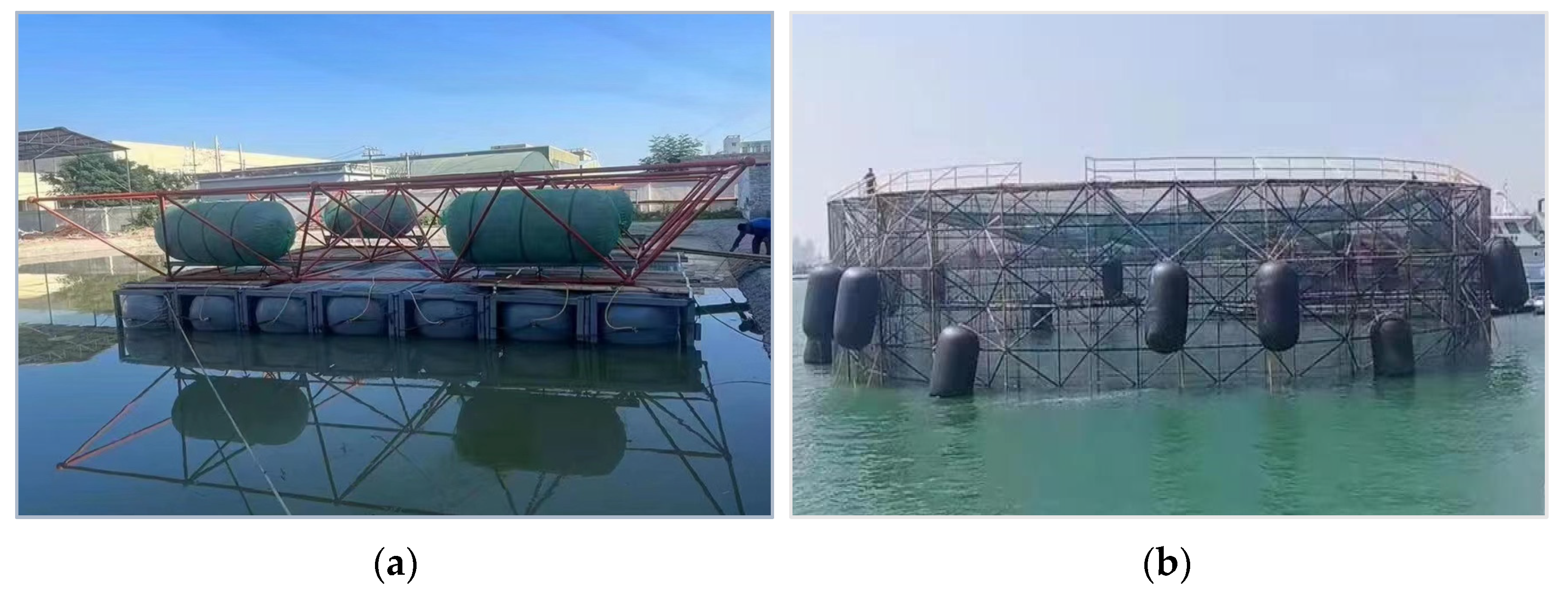
The steel grid structure is a spatial grid system comprised of members assembled through bolted ball joints based on specific geometric principles. This architectural framework offers advantages such as well-distributed stress, dependable connections, and convenient construction processes. Its applicability extends beyond terrestrial spatial frameworks, encompassing diverse settings like exhibition centers, sports venues, and industrial factories, while also finding progressive integration within the realm of marine engineering [
1,
2,
3]. Notable applications include floating platforms, deep-sea fish cages, and more, as depicted in
Figure 1.
In the marine environment, the corrosion of steel materials can rapidly lead to a reduction in the cross-sectional area and load-bearing capacity of steel components. This vulnerability represents a critical weakness that undermines the safe operation of steel grid structures with bolted ball joints [
4,
5]. To address this issue, several corrosion protection measures for steel components in oceanic settings are employed, including weathering steel anti-corrosion, hot-dip galvanizing anti-corrosion, and coating anti-corrosion techniques [
6,
7,
8]. Weathering-resistant steel anti-corrosion involves incorporating trace amounts of alloying elements into conventional steel. This process facilitates the formation of a dense oxide coating on the steel’s surface, effectively preventing further corrosion and oxidation. In contrast, the approach of hot-dip galvanizing anti-corrosion entails immersing steel components into molten zinc, resulting in the formation of an iron-zinc alloy coating on the steel’s surface. This layer is a barrier against corrosive agents, significantly enhancing the steel’s anti-corrosion capabilities. Another strategy, coating anti-corrosion, centers around applying specialized anti-corrosion coatings onto the surfaces of steel structures. These coatings establish a protective shield, effectively isolating the steel from direct contact with the external environment. Among the aforementioned corrosion protection measures, coating anti-corrosion is extensively employed in numerous practical projects owing to its benefits of low cost, ease of repair, and straightforward construction procedures. This approach has yielded a favorable effect on the external corrosion protection of members and joints, effectively controlling corrosion on the structural exterior.
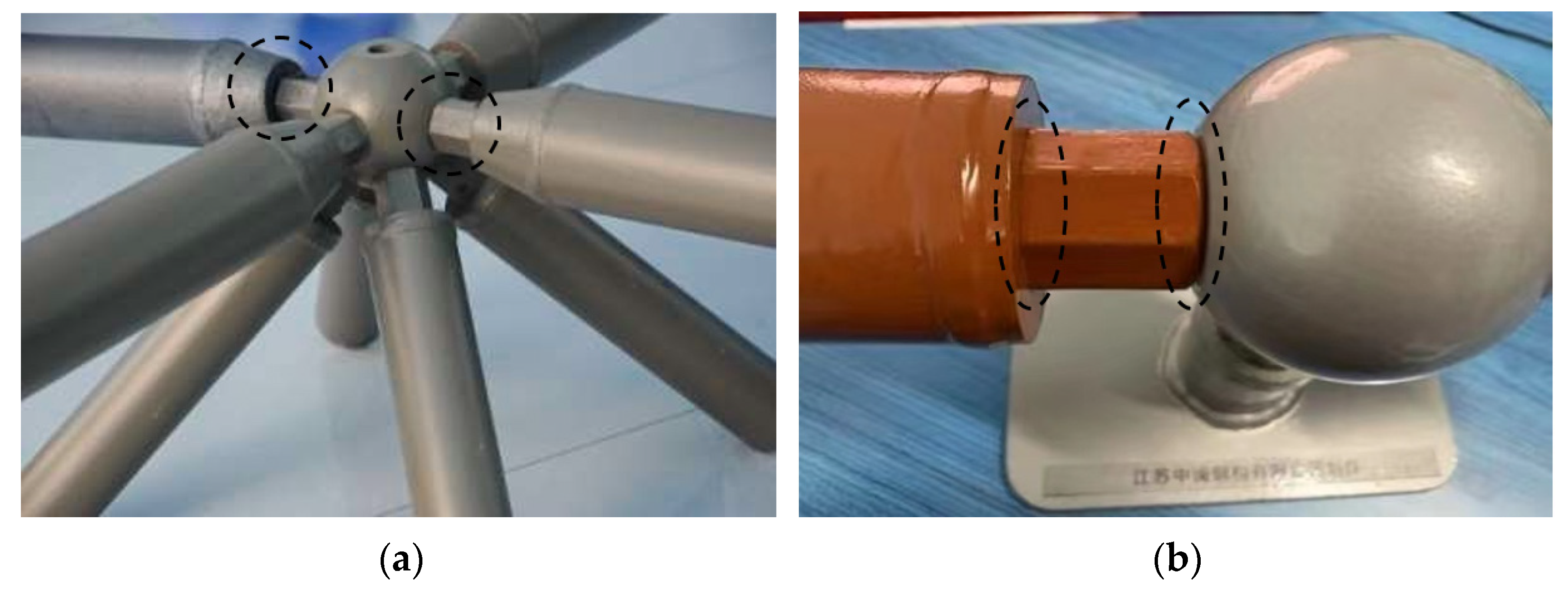
However, due to the installation gaps between the components of the bolt ball joint, as depicted in
Figure 2, seawater is prone to seep into the interior of the joint, leading to corrosion of the bolt threads and the interior of the steel pipe, which has become the main problem faced by the application of the bolt ball joint steel grid structure in the field of marine engineering. Due to the small internal space of the joint and the extremely fine components such as bolt threads, it is difficult to comprehensively cover all surfaces with coating anti-corrosion and hot-dip galvanizing anti-corrosion, and it will affect installation accuracy, making coating anti-corrosion and hot-dip galvanizing anti-corrosion not suitable for solving this problem. Although weathering steel anti-corrosion is feasible, it has certain limitations for large-scale steel structure anti-corrosion engineering due to its high cost and complex construction and maintenance.
Therefore, how to improve the joint structure and enhance the sealing performance of the joint, thereby eliminating the problem of internal corrosion caused by installation gaps, has essential research value. Huang [
9] proposed a method for achieving the sealing of bolt ball joints by adding an outer layer on the surface of the bolt ball and a sealing sleeve on the periphery of the sleeve to achieve sealing protection of the bolted ball joint. However, this sealing method is cumbersome in construction and makes it difficult to cover the outer layer when there are many connecting rods at the joint. Zhang [
10] proposed a sealed connection rod for the bolted ball joint, which seals the inside of the member by adding sealing partitions at both ends of the rod. However, this sealing method focuses solely on safeguarding the member’s internal corrosion, neglecting the corrosion vulnerability of the sleeve and bolt ball components. Furthermore, the proposed sealing methods mentioned are currently at a preliminary stage, lacking essential sealing performance analysis and experimental validation. Consequently, there exists a need for in-depth research to develop a pragmatic and viable sealing approach that not only enhances the sealing performance of bolted ball joints but also effectively addresses internal corrosion challenges.
Addressing the aforementioned concerns, this article presents a novel approach aimed at enhancing the sealing performance of bolted ball joints, thereby effectively mitigating the propensity for gap corrosion within these joints in the field of marine engineering. Firstly, a detailed explanation of the sealing method and structural design is provided. Subsequently, a finite element analysis model is established to assess the contact pressure exerted on the sealing ring across varying levels of compression. Lastly, practical air-tightness testing experiments are carried out on the manufactured joint model to empirically validate the viability and effectiveness of the proposed sealing method.
2. Ideas and Structural Design
To address the issue of seawater intrusion and corrosion in bolted ball joints arising from installation gaps, this paper considers the utilization of sealing washers to fill the installation gaps in bolted ball joints to seal the joint. Sealing washers are a prevalent component within the realm of sealing applications, and their function is to occupy the spaces between two contacting surfaces, thus forming a sealing interface to prevent the permeation or leakage of gases or liquids between these surfaces.
For achieving effective joint sealing, sealing washers must be crafted from materials exhibiting commendable compressibility and resilience. Additionally, in consonance with the operational environment and objectives of the bolted ball joint, these sealing washers should also possess attributes like corrosion resistance and longevity. Common sealing materials encompass rubber, silicone, and polytetrafluoroethylene. Among these options, Nitrile Butadiene Rubber (NBR), a prominent synthetic rubber in the sealing realm, emerges as a prime contender. Noteworthy for its exceptional qualities including heightened wear resistance, robust adhesion, impressive heat resistance, resilience against aging, and superior airtightness [
11,
12], NBR squarely meets the sealing requirements of the bolted ball joint. Consequently, this paper selects NBR as the designated material for the sealing gasket.
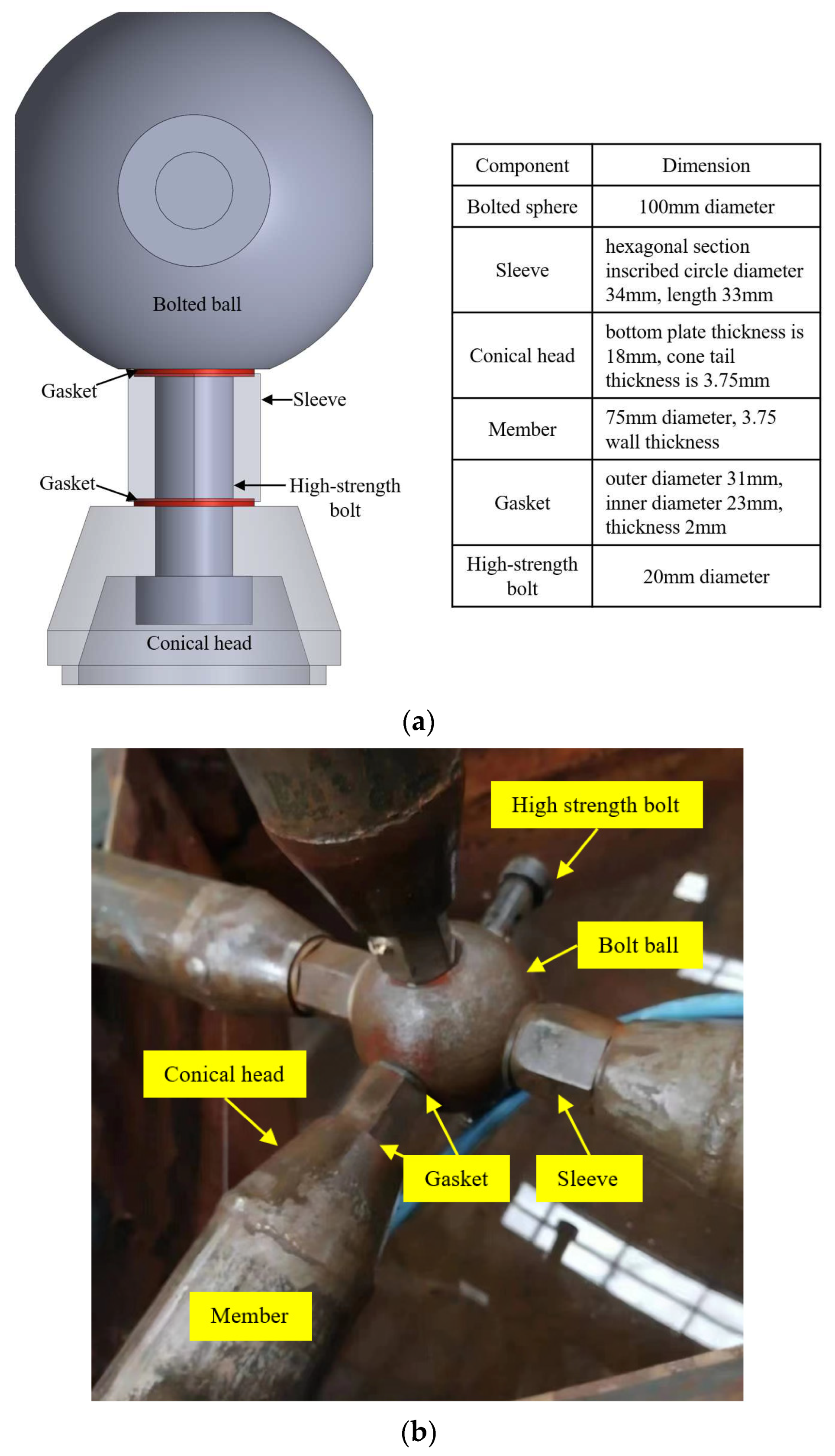
The enhanced bolted ball joint featuring a sealing structure is depicted in
Figure 3. This configuration primarily comprises a bolt ball, high-strength bolt, sleeves, pin, cone head, and sealing washer. Diverging from conventional bolted ball joints, the innovation introduced in bolted ball joints with sealed structures centers around the incorporation of circular grooves and sealing washers at both ends of the sleeve. These sealing washers are securely embedded within the circular grooves to ensure precise alignment and steadfastness during installation. Upon the tightening of the high-strength bolt, the sealing washer undergoes compression. This ingenious design effectively engenders a sealing interface within the contact gap between the sleeve and the bolt ball, and cone head, thereby thwarting the infiltration of seawater into the joint’s interior. During the installation process, the prescribed procedure entails initially positioning the sealing washer within the circular groove at each end of the sleeve. Subsequently, the sleeve and sealing washer are collectively inserted into the high-strength bolt. The subsequent step involves threading the fastening screw into the pinhole to facilitate the bolt’s insertion into the threaded hole until the predefined depth is attained.
3. Numerical simulation
3.1. Guidelines for Sealing Evaluation
Based on the inherent nature and sealing principles of NBR materials, the contact pressure between the sealing cushion and the corresponding component’s contact surface plays a pivotal role in determining the sealing efficacy of the overall structure. To establish a dependable seal, the contact pressure must surpass the pressure exerted by the sealing medium, while also maintaining a specific contact length. Consequently, the criteria used to assess the structural sealing are selected as the guiding standards for evaluating the effectiveness of the sealing structure [
13,
14]. The criteria can be expressed as a formula:
where P
c is the effective contact pressure on the sealing contact surface, and P
m is the pressure of the gas-filled inside the joint.
3.2. The Numerical Model
3.2.1. Geometric Modeling
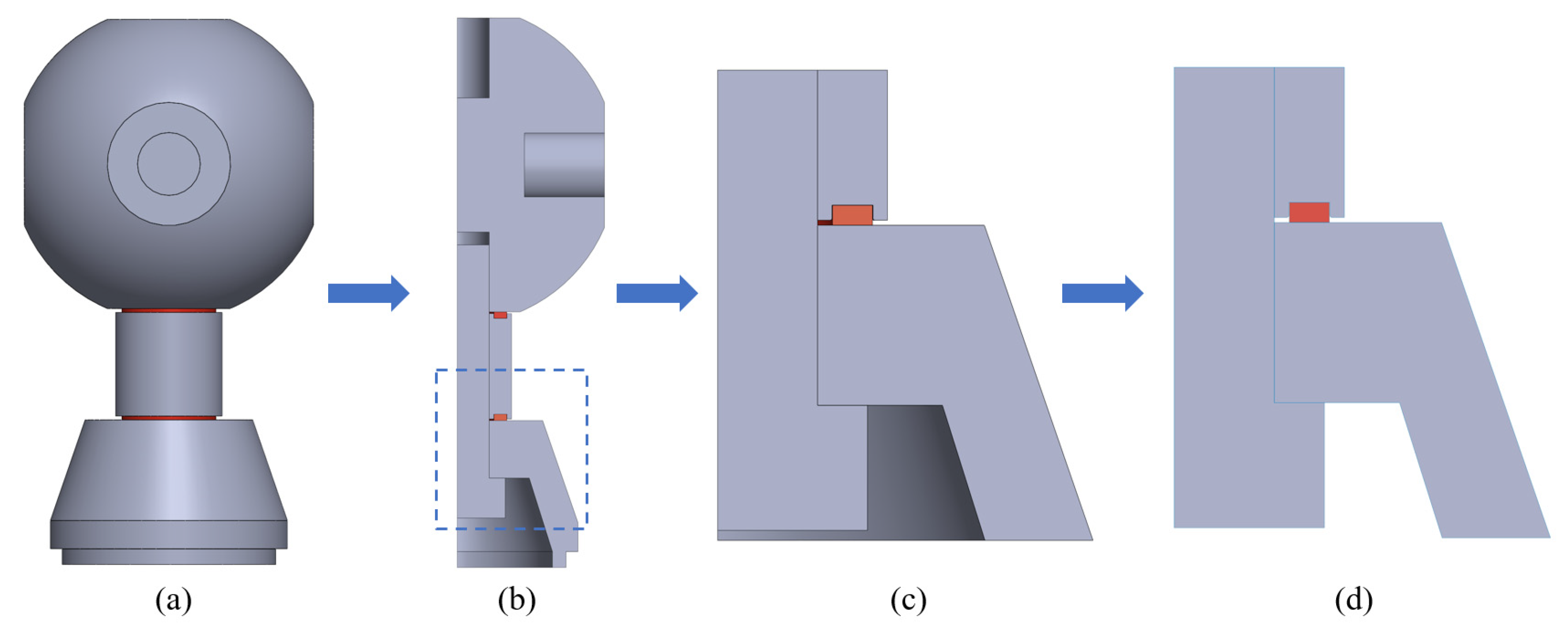
Firstly, the joint model undergoes simplification by transforming the outer section of the sleeve from a hexagonal shape to a circular one, and the resultant simplified joint model is depicted in
Figure 4a. The focal point of this study is the contact region of the seal. The analysis assumes the sleeve’s centerline as the axis of symmetry, rendering the geometry and boundary conditions of the simplified nodal model axisymmetric. Consequently, a two-dimensional axisymmetric model is employed for analysis. Due to symmetry considerations, one of the seals at the sleeve’s ends is selected for detailed analysis. The specific process for creating the model is as follows: Firstly, an assembly model of the bolted ball joint with the sealing structure is constructed using SOLIDWORKS. Subsequently, the stretch excision command is employed to derive a 1/4 model of the component under analysis. Utilizing the isometric surface command, cross-sections of each component within the joint model are replicated. Subsequently, the joint entity is removed, yielding a two-dimensional axisymmetric geometric model of the joint, as depicted in
Figure 4d. Finally, the completed joint model file is imported into the ANSYS finite element analysis software.
3.2.2. Material Constitutive Relationship
During the finite element analysis process, the components including high-strength bolts, sleeves, and cone heads are constructed using Q355 steel. Due to their minimal deformations, these components are treated as either rigid or elastic, possessing an elastic modulus of 206GPa and a Poisson’s rate of 0.3. On the other hand, the sealing ring is fashioned from NBR material, with its constitutive relationship defined through the utilization of the Mooney Rivlin 2 parameter model [
15,
16]. The corresponding strain energy density function is provided below:
where W is the strain energy, C
10 and C
01 are material-related constants, and I is the principal strain in the principal direction. The constants for C
10 and C
01 in this article are 1.87 and 0.47, respectively [
17].
3.2.3. Meshing
During the finite element analysis process, the PLANE182 planar element is employed for simulation. The PLANE182 element, a quadrilateral 4-node element, possesses the capability for plasticity, hyperelasticity, stress stiffness, large deformation, and extensive strain. This enables it to provide more accurate simulations of the deformation of incompressible hyperelastic materials.
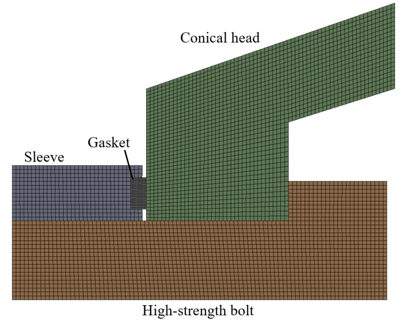
Figure 5 illustrates the mesh division of the finite element model. In this diagram, the rubber ring is assigned a mesh size of 0.2mm, while the remaining components are given a mesh size of 0.5mm. The division results in a total of 13,456 nodes and 4,292 elements. Increasing the mesh count by a factor of 1 beyond this configuration yields calculation results with an error margin below 0.45%. However, this enhancement comes at the expense of significantly increased computation time. Consequently, the mesh configuration employed in this study strikes a balance between computational efficiency and accuracy, rendering it reasonable and capable of yielding satisfactory calculation precision.
3.2.4. Contact Setting
Considering the interaction between the components of the sealing structure, the contact of the bolt with the cone head and the sleeve is set as frictional contact, and the coefficient of friction is set as 0.15. The contact of the sealing washer with the sleeve and cone head is set as frictional contact, and the coefficient of friction is set as 0.2 [
15].
3.2.5. Loads and Boundary Conditions
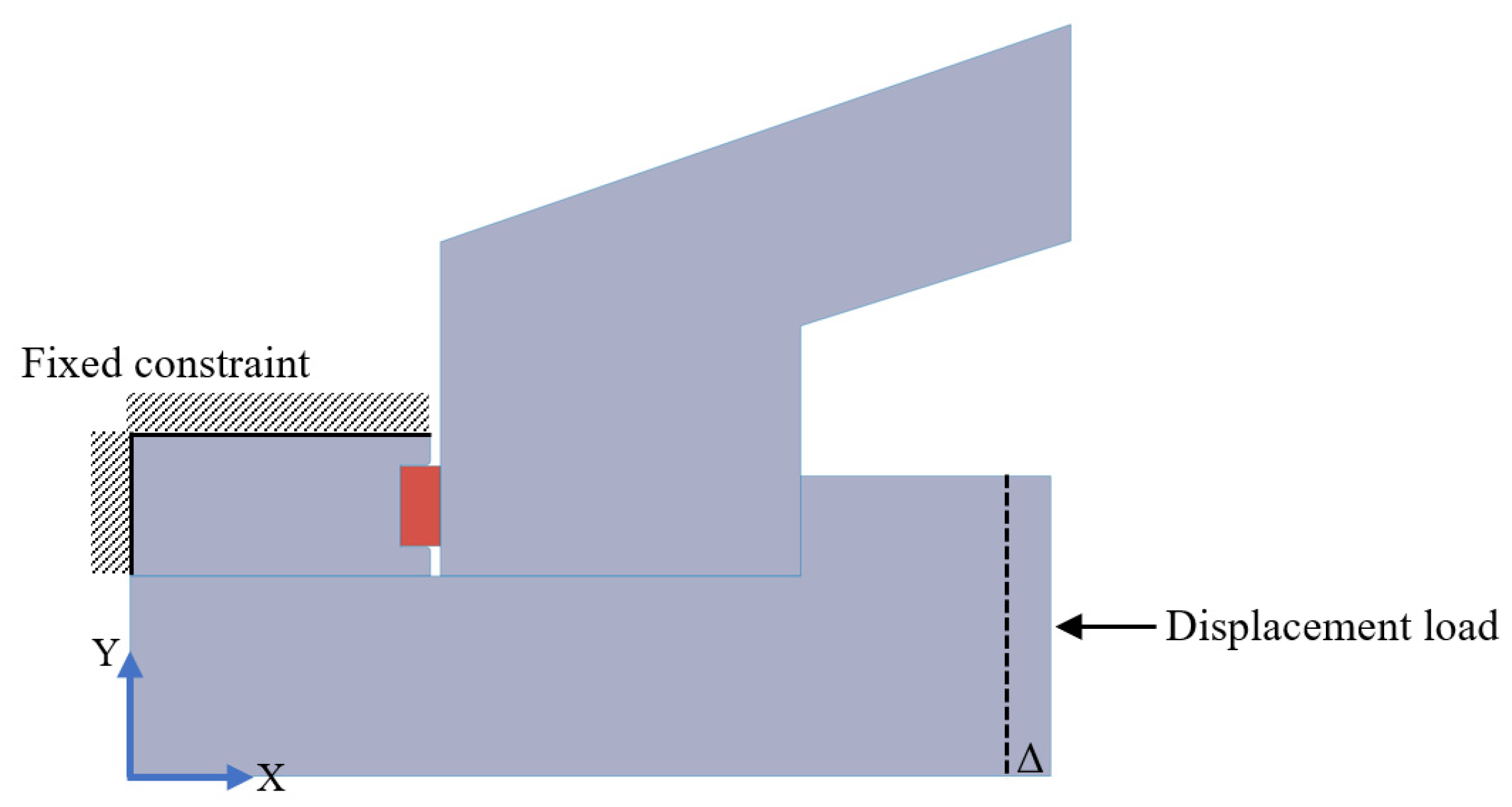
Constrain the sleeve’s left and upper boundaries in both X and Y directions, while imposing constraints in the Y direction on the bolts and cone heads. Utilizing the displacement loading mode, apply a displacement in the X direction to the right boundary of the bolt, as visually illustrated in
Figure 6.
3.3. Numerical Simulation Results
To ensure the attainment of effective sealing performance, the typical compression rate for rectangular seals falls between 8% and 14% [
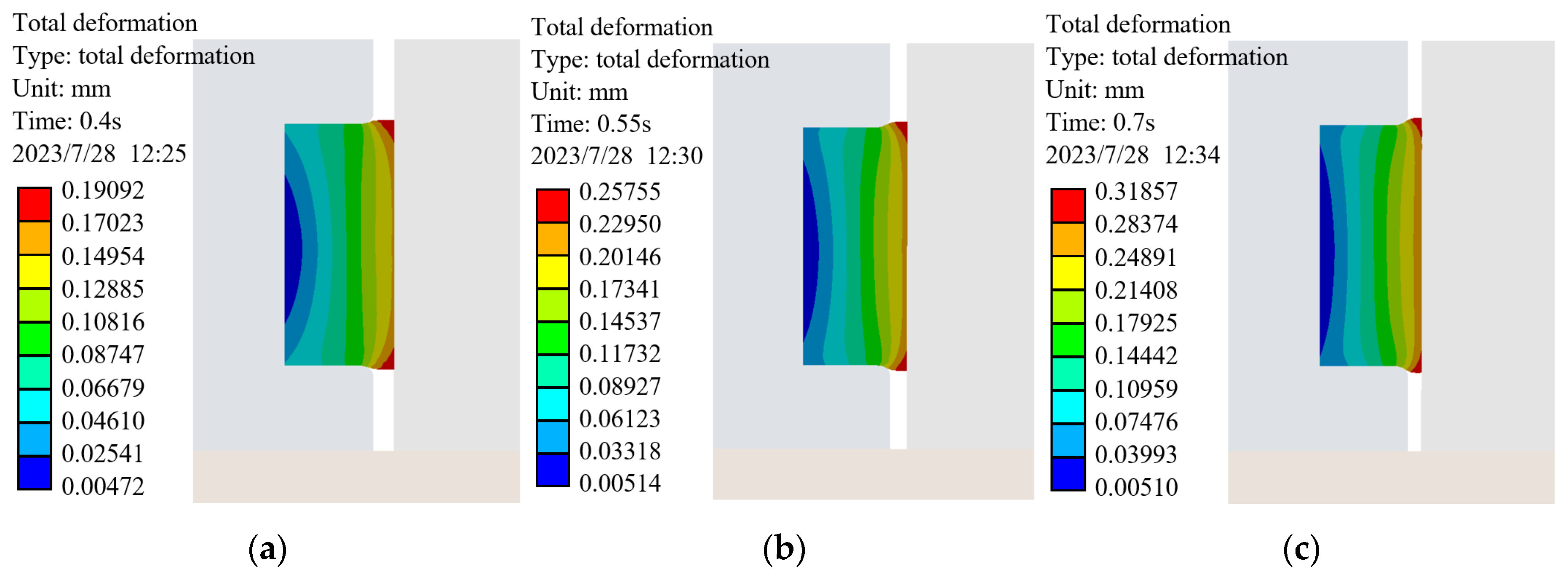
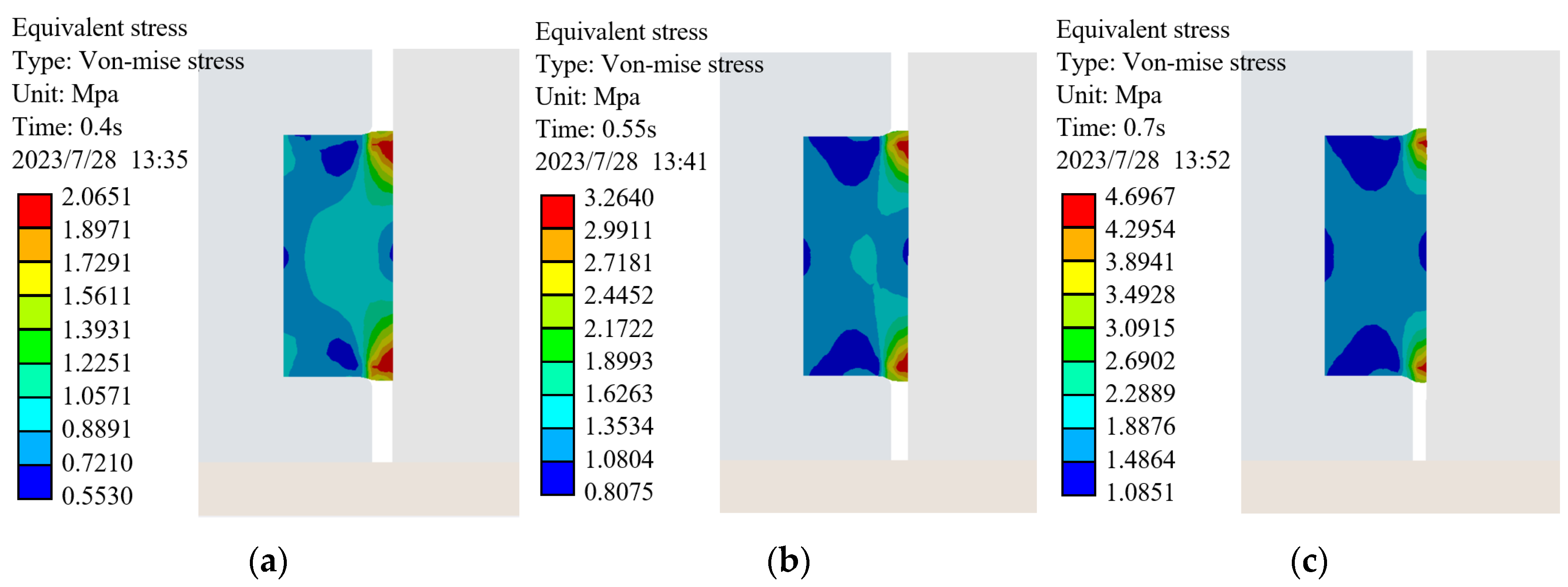
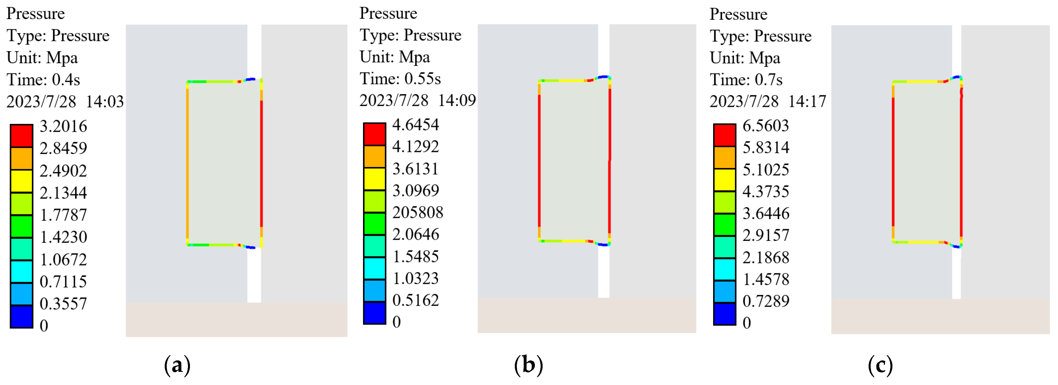
18]. For the scope of this study, the model’s compression spans from 0.16mm to 0.28mm. Leftward displacements of 0.16mm, 0.22mm, and 0.28mm are then applied to the bolt’s tail end to simulate corresponding seal compressions during the tightening process of the bolted ball joint. Subsequently, the deformation cloud diagram of the sealing washer, the equivalent force cloud diagram, and the contact pressure cloud diagram are depicted in
Figure 7,
Figure 8 and
Figure 9.
Analyzing the deformation cloud map, it becomes evident that the deformation distribution of the sealing ring maintains considerable uniformity. With the gradual increase in the compression rate, the extent of the sealing ring’s deformation also amplifies. It’s noteworthy that the most pronounced deformation regions are localized at the upper and lower extremities of the contact surface between the sealing ring and the cone head. This phenomenon is attributed to the progressive filling of the contact gap by the sealing ring during the compression, leading to a more notable deformation in the upper and lower portions of the contact surface. This phenomenon plays a pivotal role in the sealing process, ensuring the efficacy and stability of the seal’s performance.
The stress cloud diagram reveals that the equivalent stress level of the seal escalates as the compression increases. Notably, the stress values at the upper and lower extremities of the contact surface between the seal and the cone head are notably higher, exhibiting a concentration of stress. This observation aligns with the findings presented in the deformation diagram.
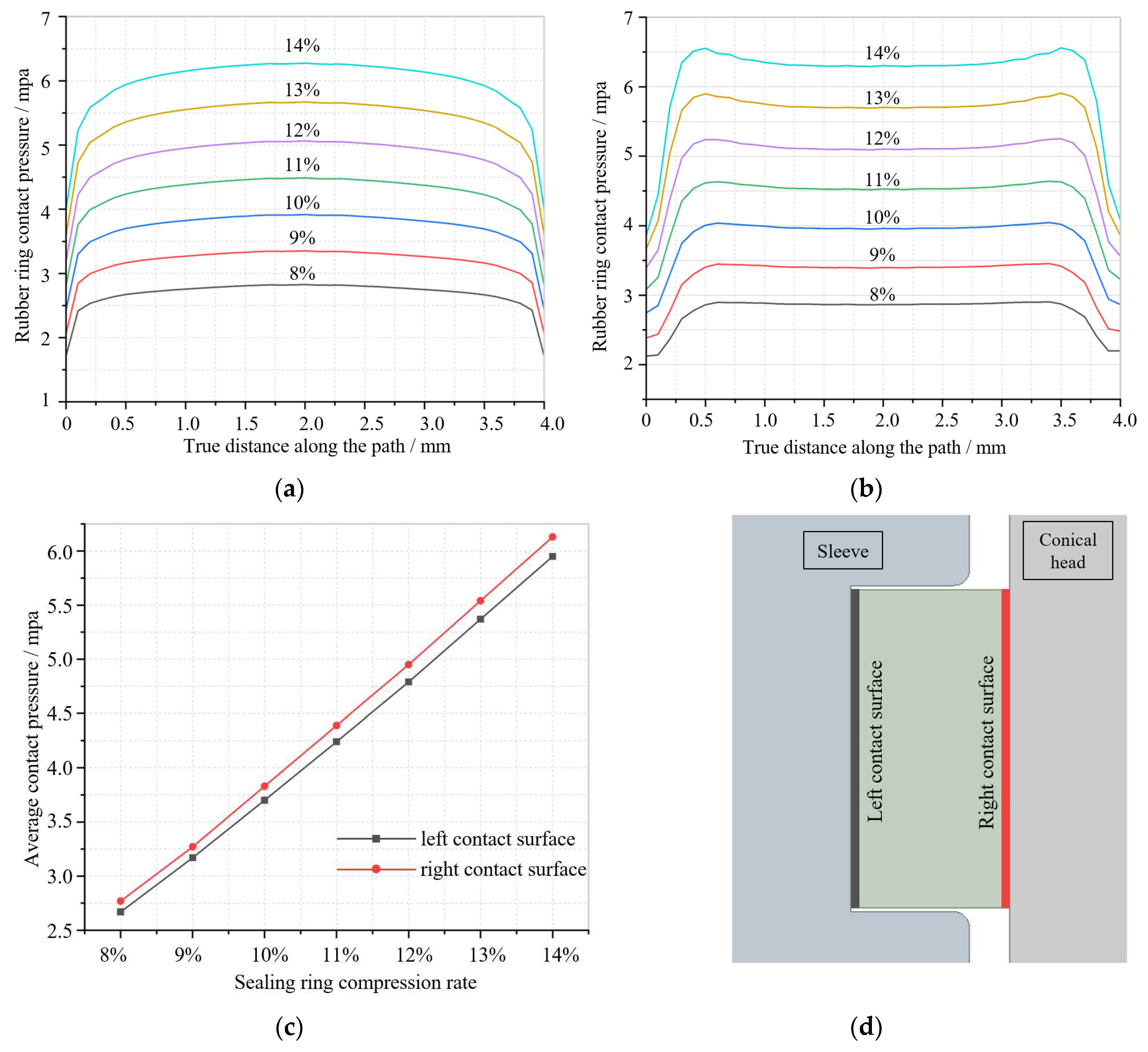
Analyzing the contact pressure cloud diagram of the sealing ring, it becomes evident that the principal sealing effect manifests on the contact surfaces located at the left and right sides of the sealing ring. Notably, the sealing performance is dictated by the smaller of these two contact surfaces. Upon data extraction, the correlation between the contact pressure on the left and right sides of the sealing surface and the actual path distance under varying compression levels is established. This relationship is visually depicted in
Figure 10.
As depicted in
Figure 10, it becomes evident that the seal’s contact pressure is most pronounced within the central region. This central section, spanning approximately 3mm long and constituting 75% of the contact area, assumes the primary role in effecting sealing. With an increase in the compression of the sealing ring, the contact pressure on the sealing surface correspondingly escalates, and their relationship exhibits an approximate linearity. At 14% compression, the sealing gasket attains a sealing pressure of 5.95 MPa. This outcome substantiates the efficacy of the bolted ball joint’s sealing structure within high-pressure contexts. Moreover, it underscores the sealing structure’s commendable sealing performance, thereby affirming its viability in marine environments for safeguarding bolted ball joint mesh structures against corrosion.
4. Experimental Testing
4.1. Experimental Design
The chosen experimental approach employs the bubble leakage detection method. This involves introducing a specific pressure of leakage-indicating gas into the test specimen immersed in liquid. This process generates a pressure differential between the interior and exterior of the airtight cavity. If there exists a gap causing leakage within the sealing cavity, the leakage-indicating gas will flow from the higher-pressure side to the lower-pressure side through the gap. This action results in the formation of bubbles around the leakage gap. This visual occurrence aids in ascertaining the presence of a leakage phenomenon within the airtight cavity [
19]. This method offers a swift and intuitive evaluation of the specimen’s sealing quality with heightened sensitivity. In this test, air serves as the leakage-indicating gas, while water functions as the displaying liquid.
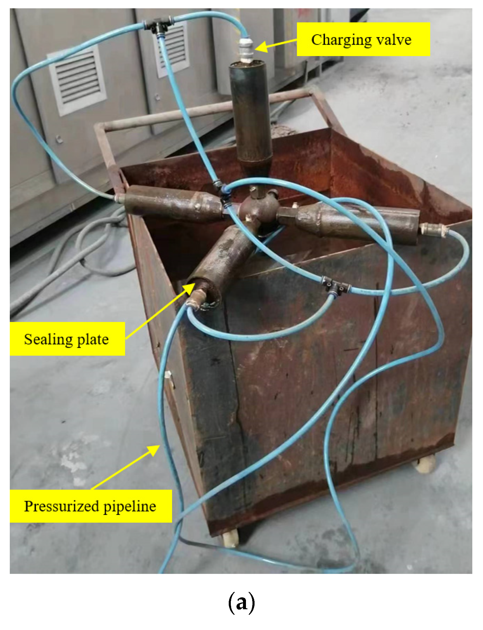
To enable inflation of the bolted ball joint’s internal pressure, a sealing plate is affixed to the end of the member, accompanied by the installation of an inflatable valve, as depicted in
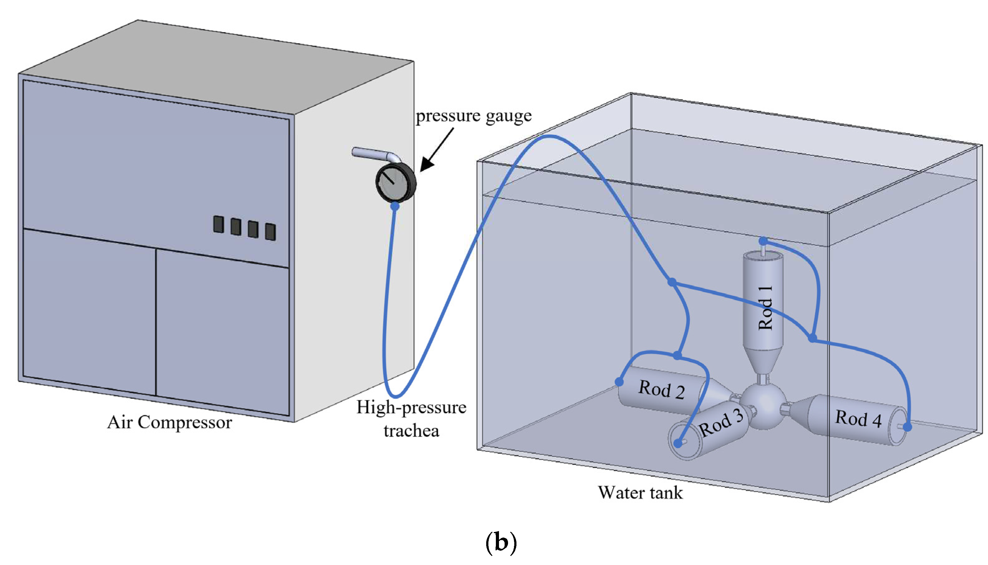
Figure 11a. Subsequently, an air compressor pump is engaged, connected to the member’s interior to instate inflation and pressurization. This process serves the purpose of assessing the sealing pressure and detecting any potential leaks within the sealing structure. To ensure heightened reliability in the test outcomes, simultaneous pressure experiments are conducted on the four members. The experimental test principle and necessary equipment are elaborated in
Figure 11b and
Table 1, respectively.
4.2. Experiment Process
The initial phase involved the assembly of the components of the bolted ball joint, with the application of a bolt torque during assembly adhering to the specified standard value of 137 N·m [
20]. Subsequently, the average compression rate of the two seals was calculated at 12.57% by assessing the distance between the cone head and the bolt ball. Following this, the inflation apparatus was linked by the test scheme and principles illustrated in
Figure 11. The air compression pump was then activated to dispense high-pressure air incrementally, with each 0.1 MPa increment being stabilized for five minutes to ascertain the presence of any leaks at the seals. In cases of normalcy, the pressure escalation continued until either a leakage phenomenon manifested or the maximum output pressure of the air compression pump was attained.
Furthermore, upon immersing the test piece in water, bubbles might emerge at the sealing point. If these bubbles do not reappear after wiping or poking, it can be inferred that the initial bubble formation site is devoid of leakage apertures. Conversely, a consistent and persistent emission of bubbles would indicate the presence of a leakage hole at the point of bubble origination [
19].
4.3. Experimental Results and Analysis
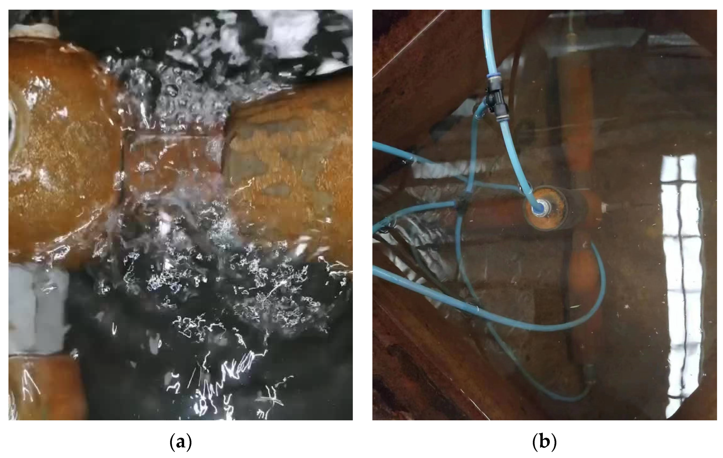
Two sets of nodal models were subjected to experimentation: the conventional bolted ball joint and the modified bolted ball joint. During the initial inflation stage of the conventional bolted ball joint, air bubbles emerged, and their quantity increased with rising inflation pressure, as depicted in
Figure 12a. Notably, the conventional bolted ball joint exhibited no sealing properties whatsoever. In contrast, the modified bolted ball joint displayed impeccable performance, exhibiting no leakage and maintaining effective sealing throughout the process of reaching the maximum inflation pressure of 0.8 MPa from the air compressor, as illustrated in
Figure 12b.
Owing to power limitations in the employed inflation equipment, the experimental gas output pressure was constrained to 0.8 MPa—a water pressure value equivalent to a depth of 81.63 meters in seawater. In practical applications of deep-sea fish cages, a typical depth of around 20 meters is employed. This result significantly bolsters the groundwork for implementing bolted ball joints in offshore environments, ensuring their dependable adaptation to the challenges presented by seawater conditions.
Additionally, the sealing method lacks experimental validation under higher gas pressure due to the limitations of the bubble leak detection method and the specific inflation equipment used. Future research should focus on conducting refined experiments to confirm the sealing method’s efficacy and validate its compatibility with the numerical simulation approach.
5. Conclusions
This paper introduces a methodology to enhance the sealing performance of bolted ball joints, offering a solution for the corrosion protection of grid structures with bolted ball joints in marine environments. Numerical simulation analyses and sealing performance tests were conducted on the bolted ball joint equipped with the sealing structure. The primary conclusions are outlined below:
(1) According to the numerical simulation results, it is evident that the sealing pressure rises proportionally with the augmentation of compression rate, illustrating a clear linear correlation between the two factors. Notably, the sealing gasket attains a commendable sealing pressure of 5.95MPa at a 14% compression rate.
(2) Regarding the seals employed in this study, the higher magnitudes of contact pressure are notably centered within the intermediate region. The primary sealing function is effectively executed by the central area of the contact surface, encompassing a length of approximately 3 mm and accounting for 75% of the total contact area.
(3) Airtightness testing experiments were conducted on both the conventional and modified bolted ball joints using the bubble leakage detection method. The outcomes revealed that the conventional bolted ball joint exhibited no sealing whatsoever, while the bolted ball joint incorporating the sealing structure demonstrated impeccable sealing performance.
(4) The sealing method for bolted ball joints provides a cost-effective solution with simple installation and maintenance. Retaining the traditional appearance of the joint, it guarantees impeccable internal sealing. This prevents seawater intrusion and corrosion, aligning perfectly with the application demands of the bolted ball joint in the realm of marine engineering.
(5) The sealing method facilitates the successful adaptation of steel grid structures, extensively employed in terrestrial settings, for utilization in marine engineering applications, encompassing offshore floating platforms and deep-sea fish cages. Analytical and computational findings underscore that this approach effectively ensures optimal sealing performance even at depths of up to 607.14 meters in seawater.
Author Contributions
Conceptualization, W.D. and G.S.; methodology, G.S. and J.G.; software, G.G.; validation, W.D., Z.L. and Y.Z.; writing—original draft preparation, J.G.; writing—review and editing, W.D.; visualization, Y.Z.; project administration, Z.L.; funding acquisition, W.D. All authors have read and agreed to the published version of the manuscript.
Funding
This research was funded by the Chinese National Natural Science Foundation, grant number U1704141 and 52178172.
Institutional Review Board Statement
Not applicable.
Informed Consent Statement
Not applicable.
Data Availability Statement
Data will be made available on request.
Conflicts of Interest
The authors declare no conflict of interest.
References
- Cao, Z. , Du, P., Chen, Z. The stability and stressed skin effect analyses of an 80 m diameter single-layer latticed dome with bolt-ball joints. International Journal of Steel Structures, 2016; 16:279–288.
- Liu W.B., Xi S.L., Cheng H.S. Analysis of the structure style selection for ocean engineering floating structure[J]. Advanced Materials Research, 2011; 163: 501-506.Author 1, A.; Author 2, B. Book Title, 3rd ed.; Publisher: Publisher Location, Country, 2008; pp. 154–196.
- Amaechi CV, Reda A, Butler HO, Ja’e IA, An C. Review on Fixed and Floating Offshore Structures. Part I: Types of Platforms with Some Applications. Journal of Marine Science and Engineering. 2022; 10(8):1074.
- Aksu R, Uguz R O, Erdogan M. Investigation, Modeling and Design of a Cathodic Protection System for Hull Structures in Marine Environment. ECS Transactions, 2016; 72(17): 163.
- Si, Q. , Tang Y., Zong L., Liu H., Kang B. Experimental Study and Numerical Simulation of the Tensile Properties of Corroded Bolt-Sphere Joints. Buildings. 2022; 12(11):1989.
- Zhao, X.D. , Xi G.F., Yang J. Comparative Study on Corrosion of Mild Steel in Natural and Simulated Marine Environment. Applied Mechanics and Materials, 2011; 66-68:1828-31.
- Lizhengli Peng, Mark G. Stewart, Robert E. Melchers. Corrosion and capacity prediction of marine steel infrastructure under a changing environment. Structure and Infrastructure Engineering, 2017; 13:8, 988-1001.
- Zeng, L.Q. , Liu M.W., Erdi Abi. Erosion characteristics of viscoelastic anticorrosive coatings for steel structures under sand flow. Construction and Building Materials, 2020; 258: 120360.
- Huang, F. , Hong Z.H., Huang P. A Sealing Structure for Bolted Ball Joints [P]. Jiangxi Province: CN217682657U,2022-10-28.
- Zhang, R.L. Sealed Connecting Rods for Bolted Ball Joint Grid Structure[P]. Tianjin: CN2571842,2003-09-10.
- Li, J.X. , Liu, P.F., Wang, S.B. Finite Element Analysis of O-ring Sealing Performance of Manned Submersible Viewports. Journal of Failure Analysis and Prevention, 2020; 20: 1628–1637.
- Zhou, C. , Chen, G., Liu, P. Finite Element Analysis of Sealing Performance of Rubber D-Ring Seal in High-Pressure Hydrogen Storage Vessel. Journal of Failure Analysis and Prevention. 2018; 18: 846–855.
- GB/T 33509-2017, General specification for mechanical seals[S].
- Zhao, Z.F. , Shi X., Hua Y.L. Performance analysis and test on the sealing structure of repair clamp for subsea pipeline. The Ocean Engineering, 2023; 41(01): 101-109.
- Bhaumik, S. , Kumaraswamy, A., Guruprasad, S. Investigation of friction in rectangular Nitrile-Butadiene Rubber (NBR) hydraulic rod seals for defense applications. J Mech Sci Technol, 2015; 29: 4793–4799.
- Song X, Huang S, Hui H. Analysis of sealing performance of a kind of profiled rubber gasket used in the radial contact seal structure. Proceedings of the Institution of Mechanical Engineers, Part E: Journal of Process Mechanical Engineering. 2021; 235(4): 857-862.
- Li, J.X. , Liu, P.F., Wang, S.B. et al. Finite Element Analysis of O-ring Sealing Performance of Manned Submersible Viewports. Journal of Failure Analysis and Prevention. 2020; 20: 1628–1637.
- Tan Jing, Yang Weimin, Ding Yumei. Finite Element Analysis of Rectangular Rubber Seals. Lubrication engineering, 2007; 02: 36-39.
- Biram J, Barrows G. Bubble tests for gas tightness. Vacuum, 1964; 14: 221-226.
- GB/16939-2016, High strength bolts for joints of space grid structures[S].
|
Disclaimer/Publisher’s Note: The statements, opinions and data contained in all publications are solely those of the individual author(s) and contributor(s) and not of MDPI and/or the editor(s). MDPI and/or the editor(s) disclaim responsibility for any injury to people or property resulting from any ideas, methods, instructions or products referred to in the content. |
© 2023 by the authors. Licensee MDPI, Basel, Switzerland. This article is an open access article distributed under the terms and conditions of the Creative Commons Attribution (CC BY) license (http://creativecommons.org/licenses/by/4.0/).
