1. Introduction
Unlike the cars that can park on the ground, vessels are impossible to be fixate on the sea. One of the safest ways to secure a vessel on the sea is to use an anchor, except by mooring. Anchors can hold a vessel that weighs more than 1,000 times its own weight. When a vessel is anchored, its safety is determined by the difference between the frictional force by the anchor and the various external forces acting on the vessel. When an anchor is dropped on the seafloor, the weight of the anchor makes it dig into the floor. Then, the frictional force of the anchor is greatly increased. Holding Force is defined as the maximum static frictional force of the anchor [
1,
2].
The holding force is one of the important indicators for the safety of the anchored vessel. However, the holding force is a physical quantity that is hard to analyze because it deals with friction on the seafloor, the big and complex shape of the vessel that makes it difficult to estimate the external force, various catenary curves change the magnitude of the anchor chain’s tension, and so on. Estimating the holding force is known to be difficult, so most of the anchor’s holding force is usually measured by actually dragging anchors on the seafloor [
3]. Nevertheless, theoretical and experimental studies on the holding force have been conducted occasionally in the field of geological oceanography and hydrodynamics. Shoji (1975) theoretically analyzed the holding forces between tension and the shape of the catenary [
4], and Moharami and Shiri (2018) carried out a reliability evaluation of the anchor’s holding force by the catenary curve [
5]. O’Neill and Randolph (2003) examined the changes in holding force according to the seafloor composition and the angle of anchor fluke through model experiments [
6]. Okazaki and Hirai (2011) studied the development of a prediction system in which operators check the expected situation of anchor dragging in missionary work [
7]. Liu et al. (2012) derived the holding force motion equation through model experiments on the dragging of anchors on the seafloor [
8]. Ren et al. (2016) studied the holding force in three stages according to the shape of the anchor when the seafloor composition was sand [
9]. In addition, various studies and designs on anchoring have been conducted [
10,
11,
12,
13,
14,
15,
16,
17,
18,
19,
20].
In a general situations, the safety of the anchored vessel can be controlled by adjusting the released length of anchor chains. However, in harsh environments such as typhoons, it is difficult to secure the safety of the vessel just by controlling the released length of anchor chains. If the net external force caused by the winds, currents, and waves exceeds the holding force of an anchor, anchor dragging occurs. Then the vessel eventually leaves the anchoring point and then strands on a sandbank or collides with other vessels. When a typhoon is about to invade, vessels usually deviate far from the expected route of the typhoon or select a less dangerous area to anchor. However, the judgment on the anchoring area and the vessel’s safety after anchoring still depend on the experience of the operators. Jung and Kong (2009) investigated 62 maritime accidents that occurred during the invasion of Typhoon Maemi (category 5) in Jinhae Bay, the Republic of Korea, in 2003, then published the results as a manual for the anchored vessels in 2009 [
21]. Other researchers simulated the anchor dragging of vessels under bad weather, including typhoons, or presented guidelines by studying them based on real situations [
22,
23,
24,
25].
The holding force of an anchor is a complicated function related to the shape of the anchor chain’s catenary curve generated by the external forces. Therefore, it is not sufficient to study independently the frictional force of anchors using geological oceanography or the external forces of vessels using fluid dynamics. It can be said that a given system can be properly understood only by considering the physical relationship between the external forces of the vessel and the holding force of the anchor, which are transmitted by the anchor chain. In this study, we estimated the conditions in which the anchor dragging occurs, and then calculated the holding force theoretically.
The contents of this paper are as follows. In section II, we described the forces of an anchored vessel as a physical system. In section III.1, we derived the tension and the length of the anchor chain, as functions of depth and tangential angle between anchor chain and seafloor. In section III.2, we derived the equations such that the length of the chain’s holding part and the tangential angle. Then in Section III.3, we derived holding force equations for the cases with or without holding part. Finally, in section IV, we summarized and discussed the results.
2. Materials
Vessels usually anchor to secure fix their position on the sea. When an external force such as wind acts on the vessel, the anchor with chains resists external force through friction on the seafloor. In normal cases, the external force and the frictional force are in equilibrium with each other. However, when the external force increases, the anchors and chains receive upward forces derived from the catenary shape of the chain, so the frictional force due to the anchor and chains is reduced. Moreover, if external force exceeds a threshold, the anchor and chains on the seafloor cannot play their role, and the anchor dragged eventually.
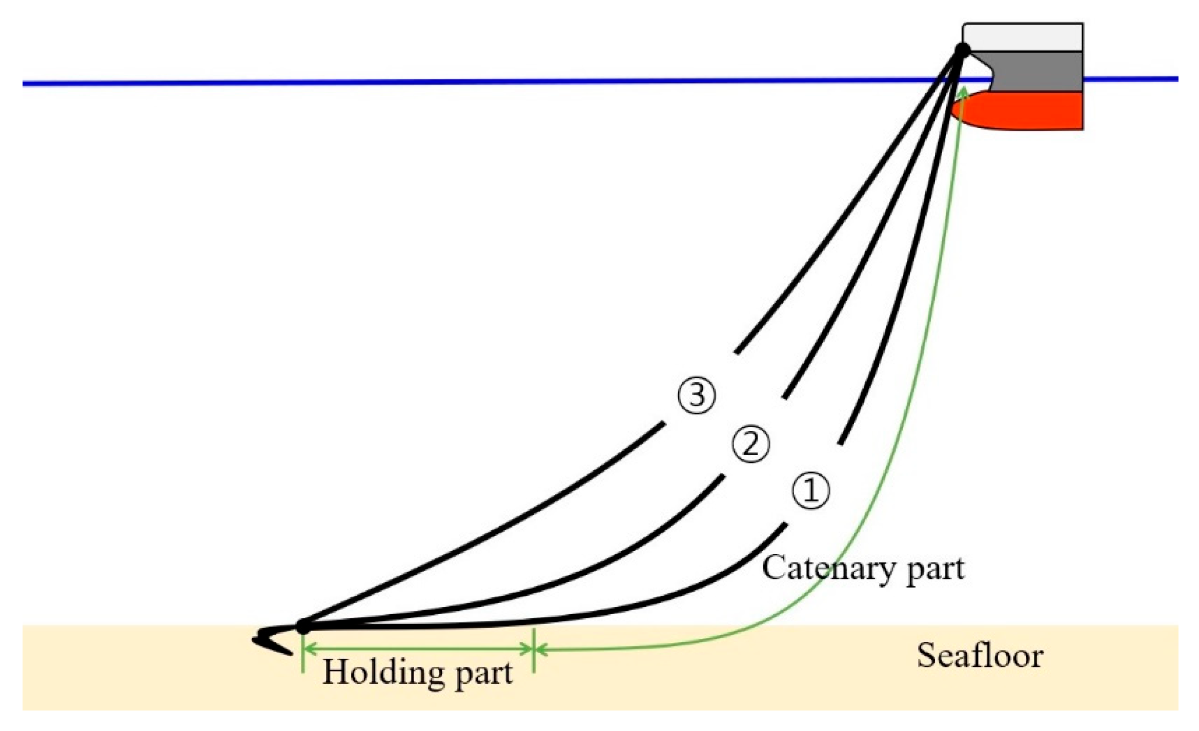
Figure 1 shows the shapes of catenary curves according to the magnitude of the external force acting on an anchored vessel. The process in which the anchor dragging is as follows.
Dragging Anchor Process
① If an external force is applied to a vessel, the curve made by anchor chains divided into the catenary part and holding part.
② When the external force increases to a critical value, the length of holding part decreases to 0.
③ If the angle between the chain and the seafloor increases by the external force, then the anchor’s normal force decreases due to the vertical component of the tension. When the external force reaches to a critical value, the anchor dragging occurs.
If the frictional forces generated by the anchor and the holding part of chain are insufficient to the external force, the anchor dragging occurs even if the length of the holding part is not 0.
Figure 1.
shape of catenary curve on an anchored vessel according to the external forces.
Figure 1.
shape of catenary curve on an anchored vessel according to the external forces.
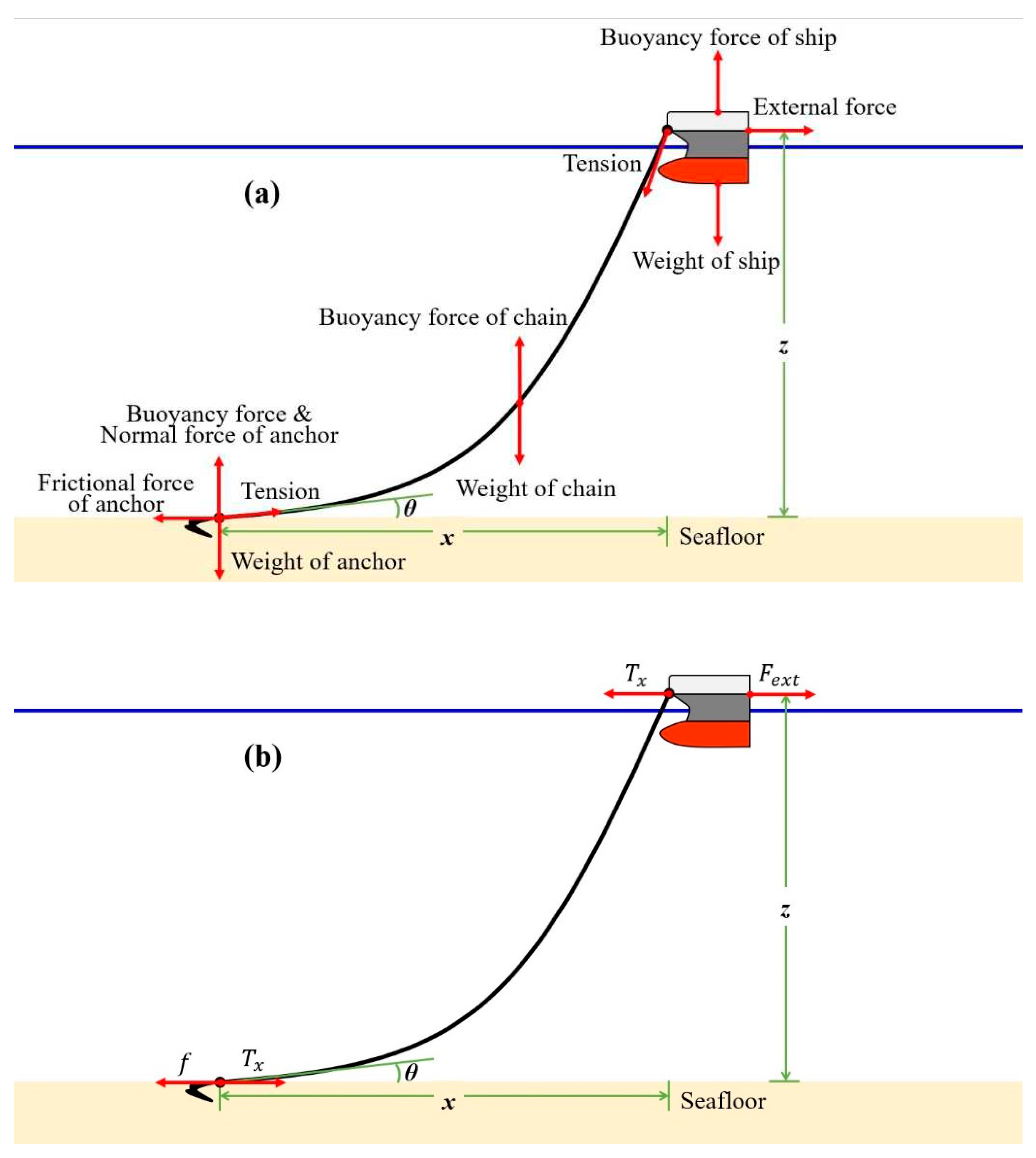
Figure 2a shows all forces acting on a vessel. If we neglect the vertical motion of a vessel caused by a wave, we can consider only the horizontal forces because all vertical forces are canceled out of each other.
Figure 2b shows horizontal forces, i.e., external force (
), horizontal components of tension
, frictional force on seafloor
.
Table 1 shows the all the forces constituting these three horizontal forces and the independent variables that determine them. In most cases, the external force
, the horizontal tension
, and the friction force
are balanced with each other, so anchor dragging does not occur. However, in the extreme situation, if the external force is bigger than the frictional force, anchor dragging occurs, and the system moves as shown in Equation (1) according to Newton’s second law.
Table 1.
Constituting forces and variables of horizontal forces.
Table 1.
Constituting forces and variables of horizontal forces.
| Forces |
Constituting Forces |
Variables |
|
: wind-driven force |
: wind speed |
|
: current-induced hydraulic force |
: current speed |
|
: drift force by wave |
: wave height |
|
: horizontal component of tension |
(: position of vessel (origin: anchor)
: length of catenary
: angle |
|
: frictional force by anchor |
|
|
: frictional force by anchor chains |
|
: frictional force by sinker |
Let the holding force
be the maximum static frictional force generated by the anchor and the chains on the seafloor. When there is no anchor dragging, the external force must be smaller than the holding force. However, the external force exceeds the holding force when the anchor dragging occurs. Equation (2) shows the relationships between the forces whether the anchor dragging occurs or not.
3. Analysis of Holding Force
3.1. Tension of Catenary Curved Chain
The tension acting on a catenary curved chain depends on the weight per unit length of the chain.
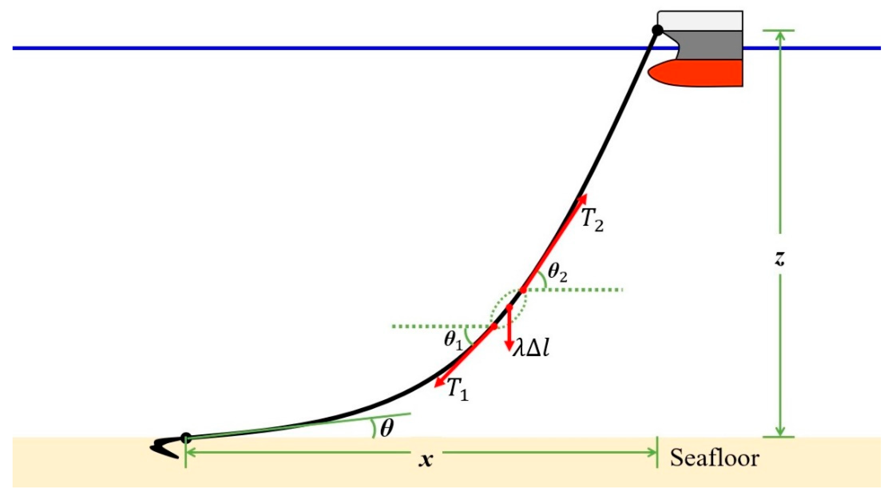
Figure 3 is a diagram showing the three forces: ①
is the weight of infinitesimal length
of the chain with a weight per unit length is
, ② tension
and
act on both ends of the
. According to
Figure 3, the horizontal component and vertical component of the
and
must satisfy the Equation (3).
; is the weight per unit length, is the infinitesimal length of chain, and are tensions acting on both ends of the
Figure 3.
Tension acting on a small length
Figure 3.
Tension acting on a small length
With some calculations, we could drive Equations (4)~(6) the vertical coordinates
of the vessel, the length
of the catenary part, and the horizontal tension
for tangential angles
, respectively. For the derivation of the equations, refer to
Appendix A.
3.2. Holding force before Anchor Dragging:
Anchor is usually dropped into a sea to keep a vessel in place. If an anchor alone is not enough to secure the vessel, concrete sinkers may be added to the anchor increase the holding force.
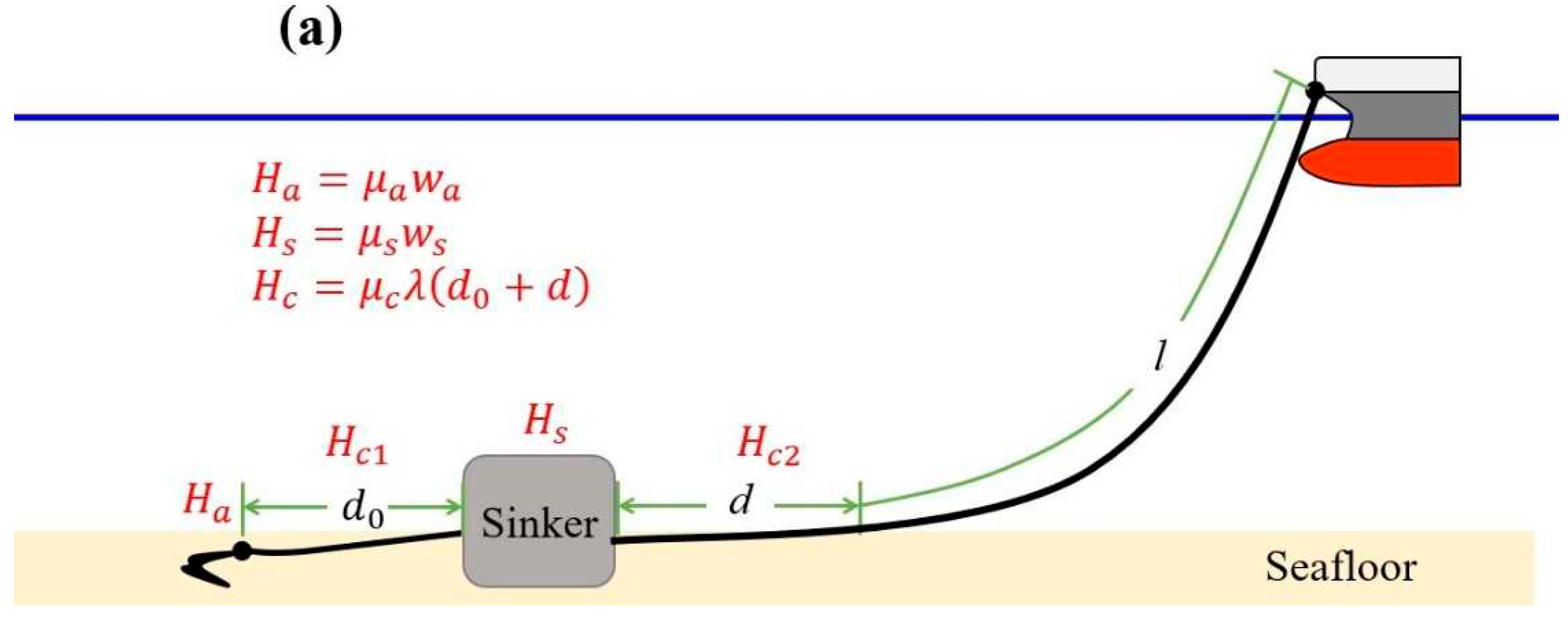
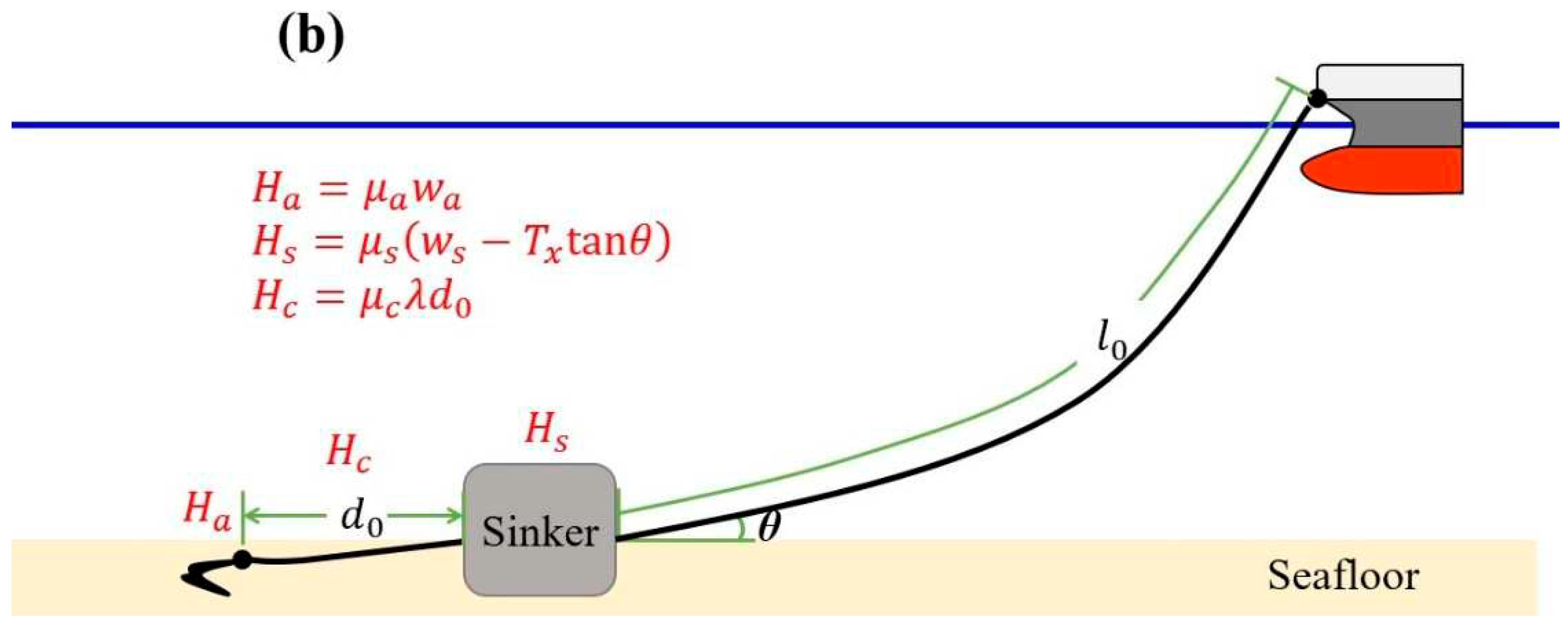
Figure 4 compares two cases that represent the shape of the catenary part when a sinker exists.
Figure 4a represents the case that tangential angle
between the catenary part of anchor chain and the seafloor is
. Then the chain of length
is divided into a holding part of length
and a catenary part of length
.
Figure 4b represents the case that there is no holding part. In this case, angle
is bigger than
.
(); (b) ()
Equations (7) and (8) show the length
of the holding part and the angle
between the catenary and the seafloor using
and
as independent variables. For the derivation of the equations, refer to
Appendix B.
where there is the holding part:
where there is no holding part:
Now, consider the holding forces by anchor, sinker, and chain. Because the sinker is connected to the catenary curved chain, the normal force of the sinker is changed by the shape of the curve. However, the normal force of the anchor is constant, so the holding force due to the anchor is a constant value, as in Equation (9).
Equation (10) shows the holding force of chains, is proportional to the length of the chains lying on the seafloor.
; is holding coefficient of chain,
is weight of chains lying on the seafloor,
is weight of chains per unit length,
is length of the chains between anchor and sinker,
is length of the holding part
Finally, as shown in Equation (11), the holding force of the sinker is proportional to the normal force of the sinker. In this case, the normal force of the sinker is reduced due to the vertical component of the tension.
; is holding coefficient of sinker,
: weight of sinker in the water,
: horizontal component of tension
Thus, total holding force on the system can be written as in Equation (12).
3.3. Holding Force at Anchor Dragging:
When the external force, tension, and holding force are balanced with each other (i.e.,
), anchor dragging occurs. Therefore, by putting
and substituting
in Equations (6), (11), and (12) with
, we could derive holding force equations (13), and (14) when the anchor dragging occurs.
When the chain is released sufficiently, the length of the holding part
is greater than 0, resulting in the tangential angle of 0° between the chain and the seafloor. Anchor dragging may also occur in this case. Equations (15) and (16) show the length of the holding part
and the holding force
at the moment of the anchor dragging where the holding part exists. For the derivation of the equations, refer to
Appendix C.
The length of the holding part
should not be negative in Equation (15). Thus in this case, it can be considered as the tangential angle
between the chain and the seafloor is greater than 0°. Equations (17) and (18) show the tangential angle
and the holding force
at the moment of the anchor dragging where the holding part does not exist. The information of Equation (15)~(18) is that anchor dragging can occur in both cases with or without holding part. For the derivation of the equations, refer to
Appendix C.
Table 2 shows the ratio of holding force using Equation (14) according to the holding coefficients of the anchor (sinker) and the tangential angle between the anchor (sinker) and the seafloor. By Dove’s experiment, it is known that the holding force decreases by 1/4 where
, and decreases by 1/2 where
[
5,
26]. However, we can see Dove’s results are consistent only if the holding coefficient is about 4 in
Table 2. This inconsistency means that the prediction of the decreasing ratio of the holding forces only by the tangential angle
can give us inaccurate information because the holding force depends on two factors:
and
(
).
4. Discussion
We comprehended the safety of vessels by studying the holding force acting on anchored vessels. The holding force of an anchor is strictly analyzed by mathematical and physical approach, which has been known as a difficult problem in the field of shipbuilding engineering or navigation. In order to predict and prevent the anchor dragging in extreme situations such as typhoons, this paper mathematically and physically analyzes the tension of the anchor chain deducing the catenary curve equation and holding force of the anchor, then strictly comprehends the relationship between tension and holding force.
The force acting on the anchor was analyzed, and the horizontal component of tension was newly derived as a function of the depth of the sea, the length of the catenary part, and the angle with the seafloor (Equation (6)). Moreover, the holding force for a sinker attached vessel was analyzed. The anchor chains transmit the external force to the sinker (anchor). When the external force exceeds the threshold, the anchor dragging occurs in both cases with or without the holding part of anchor chain. If there is not a holding part, the holding force decreases due to the decrease of normal force of the sinker (anchor). In this case, to make the anchor and the sinker play their intended roles, it is necessary to increase the number of released anchor chains. However, as the length of released anchor chain increases, the radius of movement of vessels increases, so the risk of collisions with other vessels or structures may increase. Therefore, increasing the safety of anchored vessels by controlling the amount of released chain should be adjusted according to the situation. In this study, the angle between the holding part and the seafloor, length of the holding part, and the holding force are systemically derived (Equations (15)~(18)).
With these results, we could provide more symbolic equations describing the anchor dragging moments, instead of the convention of using inaccurate approximation values. The holding force equations derived in this paper could provide the more accurate ways for a vessel design, and the improved guides for preventing anchor dragging. In the future, if additional research is conducted on various anchor dragging cases, the safety of anchored vessel in a harsh environment may be further comprehended.
Author Contributions
conceptualization, S.M. and K.O.; methodology, S.M.; validation, K.O.; writing—original draft preparation, S.M.; writing—review and editing, K.O.; funding acquisition, S.M.
Funding
This work was supported by the Korea Naval Academy Maritime Institute in 2023.
Conflicts of Interest
The authors declare no conflicts of interest.
Appendix A: Forces at a Catenary Curve
In the catenary part, when
is the weight per unit length of catenary part, weight of infinitesimally small length,
, is
. Let
and
be the tensions acting on both ends of
, and let the angles be
,
at both ends to horizontal, respectively, then the horizontal components of the two tensions must be the same, but the vertical components are different by
. (see
Figure 3).
Then,
Hence,
Thus,
Then,
If both sides are integrated with respect to
and
,
The vertical coordinates of the vessel can be derived as shown in Equations (A9) by integration of Equation (A8).
• vertical coordinate of the anchored vessel
The length of the catenary part is derived through integration as shown in Equation (A10).
• length of the catenary part
Now, we can obtain a general formula for horizontal tension using the relationship between
and
by combining Equations (A9) and (A11).
Since,
is satisfied for any
Finally,
is summarized as shown in Equation (A13).
Horizontal Tension of the catenary
Appendix B: before anchor dragging
In normal cases where no anchor drag has occurred, Let the length of the holding part be
, then from Equation (A13) we can get following equations about
, and
.
By squaring Equation (B4) using
,
Appendix C: at the Moment of Anchor Dragging
The horizontal part of chain’s tension and the anchor’s holding force are as Equations (C1)~(C2).
When the anchor dragging occurs, the horizontal tension
, and the holding force
of the system should be equal.
• where there is the holding part:
If the solution of Equation (C5) is substituted for Equation (C2), then,
• where there is no holding part:
From equations (C1)~(C2),
By squaring Equation (C11) using
,
If the quadratic equation solution of Equation (C13) is substituted for Equation (C2) and solved, we can get
and
at the moment of anchor dragging, as shown in Equations (C14)~(C15).
References
- LIM, Bong-Taek; KO, Jae-Woo; KIM, Byoung-Suk. A study on theoretical consideration to the holding power and holding power coefficient of war vessel anchor. J. Navig. Port Res. 2015, 39, 1–6. [Google Scholar] [CrossRef]
- Kim, M.-S.; Ahn, J.-Y.; Lee, C.-H. Evaluation of Holding Power by Tension Meter for Anchoring. J. FISHRIES Mar. Sci. Educ. 2019, 31, 682–692. [Google Scholar]
- Sato, H. A study on the holding capacity of anchor. Journal of the school of marine science and technology. Tokai Univ. 2005, 3, 31–39. [Google Scholar]
- Shoji, K. Study on the Motion of a Moored Body and the Tension of Mooring Lines. J. Soc. Nav. Arch. Jpn. 1975, 1975, 233–246. [Google Scholar] [CrossRef] [PubMed]
- Moharrami, M.J.; Shiri, H. Reliability assessment of drag embedment anchors in clay for catenary mooring systems. Mar. Struct. 2017, 58, 342–360. [Google Scholar] [CrossRef]
- O'Neill, M.P.; Bransby, M.F.; Randolph, M.F. Drag anchor fluke–soil interaction in clays. Can. Geotech. J. 2003, 40, 78–94. [Google Scholar] [CrossRef]
- OKAZAKI, Tadatsugi; HIRAI, Yurie. Development of a support system to predict dragging anchor phenomenon for mariner. In Proceedings of the 2011 6th International Conference on System of Systems Engineering., 2011. p. 185-190.
- Liu, H.; Liu, C.; Yang, H.; Li, Y.; Zhang, W.; Xiao, Z. A novel kinematic model for drag anchors in seafloor soils. Ocean Engineering 2012, 49, 33–42. [Google Scholar] [CrossRef]
- Ren, X.Y.; Lei, Z.M.; Sun, L.; Yan, S. Model tests of dragging hall anchors in sand. J. Mar. Sci. Technomogy 2016, 24, 26–31. [Google Scholar]
- Lammes, R.R. and Siemers, R.W., 1988. “Soil Mechanics of Drag Embedment Anchor in Sand.” Faculty of Civil Engineering, Offshore Engineering Major, Delft University of Technology.
- Degenkamp, G. and Dutta, A., 1989. “Soil Resistances to Embedded Anchor Chain in Soft Clay.” J. Geotech. Eng. Vol 115, No. 10.
- House, A., Drag Anchor and Chain Performance in Stratified Soils.” Geomechanics Group, Report 1319, The University of Western Australia, 1998.
- Lin, K. and Randolph, M.F., 1998. “Numerical Analysis of Stresses and Displacements in Layered Soil Systems.” Geomechanics Group, Report G1334, The University of Western Australia.
- Neubecker, S.R. and Randolph, M. F. “The Kinematic Behavior of Drag Anchors in Sand.” Can. Geotech. J. 1996, 33, 584–594. [Google Scholar]
- Thorne, C.P. Penetration and Load Capacity of Marine Drag Anchors in Soft Clay. J. Geotech. Geoenvironmental Eng. 1998, 124, 945–953. [Google Scholar] [CrossRef]
- Navy, Naval vesselbuilding(SU)-GI-06-007(2004), “Design Criteria of Anchor and Anchor Chain”. 2004.
- Mierlo, R. v., “Anchor Trajectory Modeling.” Faculty of Mechanical Engineering, Offshore Engineering Major, Delft University of Technology, 2005.
- Murff, J.D., Randolph, M.F. & Elkhatib, S., Kolk, H.J., Ruinen, R.M., Strom, P.J. and Thorne, C.P., 2005. “Vertically Loaded Plate Anchors for Deepwater Applications.” Frontiers in Offshore Geotechnics ISFOG.
- Ruinen, R.M., 2005. “Influence of Anchor Geometry and Soil Properties on Numerical Modeling of Drag Anchor Behavior in Soft Clay.” Frontiers in Offshore Geotechnics ISFOG.
- Miedema, S.A., Lagers, G.H.G., Kerkvliet, J., “An Overview of Drag Embedded Anchor Holding Capacity for Dredging and Offshore Applications”. WODCON, Orlando, USA, 2007.
- Jung, C.-H.; Kong, G.-Y. A Study on the Development of Anchoring Manual for T. S. HANBADA, J. Kor. Soc. Marine Env. Safety 2009, 15, 49–55. [Google Scholar]
- Lee, Y.-S.; Jung, Y.-C.; Kim, S.-W.; Yun, J.-H.; Bae, S.-H.; Guyen, P. A Study on the Limit of Anchor Dragging for Vessel at Anchor(Ⅰ), J. Navig. Port Res. 2005, 29, 357–363. [Google Scholar] [CrossRef]
- Jung, C.-H.; Kong, G.-Y.; Bae, B.-D.; Y.-S., Lee. Analysis on the Pattern of Dragging Anchor in Actual Vessel. J. Navig. Port Res 2009, 33, 505–511. [Google Scholar] [CrossRef]
- Jung, C.-H.; Lee, Y.-S.; Kim, J.-S.; Kong, G.-Y. A Study on the Holding Power Coefficient of AC-14 type and ASS type Anchor in Actual Vessels, J. Navig. Port Res. 2011, 35, 613–618. [Google Scholar] [CrossRef]
- Jung, C.-H.; Kong, G.-Y. A Study for the Evaluation of the Force by the Wind on the Vessel at Anchoring, Korean Soc. Mar. Environ. Saf. 2009, 15, 223–228. [Google Scholar]
- Yoon. The theory and executive ability of Ship control, Se-jong Publisher, 2014; pp. 1-15.
|
Disclaimer/Publisher’s Note: The statements, opinions and data contained in all publications are solely those of the individual author(s) and contributor(s) and not of MDPI and/or the editor(s). MDPI and/or the editor(s) disclaim responsibility for any injury to people or property resulting from any ideas, methods, instructions or products referred to in the content. |
© 2023 by the authors. Licensee MDPI, Basel, Switzerland. This article is an open access article distributed under the terms and conditions of the Creative Commons Attribution (CC BY) license (http://creativecommons.org/licenses/by/4.0/).
