1. Introduction:
About a half of European railway lines are still
not electrified [
1], this problem also regards
highly developed countries and railway network such as Germany [
2] in which there is still an high percentage of
Diesel passenger trains operating under lines whose electrification is not
complete, since in some cases the complete electrification of a railway line
with low traffic intensities in not sustainable in terms of construction and
maintenance costs. The percentage of not electrified lines in many
extra-European countries is even higher. Rolling stock that is used to manage
both passenger and freight traffic on these lines is powered with internal
combustion engines, mostly DIESEL engines with Hydraulic or Electric
transmission systems. The substitution of ICE(Internal Combustion Engine ) with
another electric power source or storage should be proposed to increase
sustainability an environmental impact in terms of direct emissions of CO
2.
Also a simple hybridization of a Diesel-Electric locomotive as proposed by
Magelli[
3] can significantly reduce emissions.
Proposed alternatives[
4]
are electric storages such as batteries [
6] or
hybrid hydrogen fuel cell systems[
7,
8]. Both
technologies are still affected by some technological limitations that are
often studied in comparative studies such as the ones recently proposed by
Zenith[
8] and Cole[
9].
Results of this comparative studies are deeply influenced by the technological
limits of considered components which are continuously shifting due to the
continuous technological improvements. Usage of hybrid hydrogen fuel cell
systems is constrained by poor performances of fuel cell systems during fast
transients and in presence of partial loads as stated by simplified aging
models that are proposed as example by Zhang[
11].
This constraint involves the adoption of power buffer electric storage systems
that should be realized with high power batteries, with capacitors or
alternatively with an optimized mix of both technologies as investigated by
Fragiacomo [
12]. This feature also involves a
limitation of regenerative braking due to the limited size of buffer storages
and to the way in which power flows are managed. Hydrogen fuel cell systems of
commercially available trains such as Alstom Coradia[
13]
currently exhibit an autonomy which is far higher respect to corresponding
battery-operated solutions. However a further increase of the specific energy
stored and consequently of autonomy is constrained by advances of Hydrogens
storage systems, since current technology of pressurized hydrogen tanks it
substantially constrained to maximum operating pressures of 350-700bar for
which the storage of 1kg of hydrogen involve an equivalent weight of the tank
from eleven to fifteen times higher, as stated by technical documentation
available on line[
14,
15]. Also, high pressure
compression of hydrogen involves an appreciable energy consumption negatively
affecting “from well to wheel” efficiency and sustainability[
16]. On the other hand, despite specific energy
limitations of batteries[
17] that are
currently adopted for railway applications (less than 100-120Wh/kg) there is a
clear indication of rapid trend of cells and batteries proposed for automotive
market[
18,
19]. So, there is the well-founded
opinion that in about 20-30 years from now performance of batteries should be
feasible for a near to limitless application on future rolling stock. Also, it
should be considered that batteries are reversible electrochemical storages
that allow an extensive use of regenerative braking on railway vehicles.
There is a further opportunity for the usage of
battery-operated rolling stock that is represented by partially electrified
lines in which a multi-modal usage of the system should be convenient and
feasible: in this case the mission is performed along lines which are
electrified only in some sections. This is quite common conditions, since as
example a part of the mission should be performed along a high traffic route
for which cost of line electrification is tolerable. Otherwise, the remaining
part of the line should remain not electrified for different reasons such as a
relatively low intensity of railway traffic respect to the construction and
maintenance costs of the infrastructure. This scenario has been studied since
2013 by Hoffrichter et al.[
20] which proposed
a multi-modal solution in which propulsion of electric unit is alternatively
granted by diesel units or collected from the line according to different
availability in different sections of the simulated line.
Recent studies of Abdurahman[
21] also demonstrate that the environmental impact
of service on partially electrified line can be much more sustainable respect
to a service managed with conventional Diesel Units
In the last two-three years multimodal solutions in
which the same tram or train can be alternatively supplied by overhead line or
by on board storage systems has been proposed and studied starting from tram
and suburban railways[
22] to railway
applications [
23,
24]. in this article the use
of multimodal passenger BEMU (Battery Electric Multiple Unit) on steep railway
lines built in hilly or mountainous territories is proposed. Respect to
previous studies a particular attention is focused on the following aspects
which also represent the innovative or at least more significant contribution
of this work:
Proposed benchmark test train is inspired to existing industrial products (Diesel and Hybrid Multiple Units) which are quite interesting for some application scenario such as local passenger lines on western Europe, but it introduces some significant innovations especially for what concern adopted powertrain layout and power-management system.
Adopted batteries are inspired to recent industrial products currently assessed for railway applications, also considering a proper management of their depth of discharge to assure a feasible level of reliability for proposed application.
Proposed mission profiles correspond to existing railway lines crossing mountain or hill regions, that impose increased traction loads and regenerative braking. Simulation take count also of consumptions of auxiliaries (such as example heating, ventilation, and air conditioning) not only when the train is moving but also during train stops or during parking at terminus stations.
Recharge of on-board batteries is supposed to be performed using exclusively the power collected under a standard 3kV catenary using a conventional railway pantograph, so the whole system is designed and simulated also considering power and current limits imposed by regulations in force[
25].
Obtained results are quite interesting for a potential immediate application of battery operated trains to partially electrified lines
Both proposed simulation tools/models can be useful and interesting for a further optimization not only of proposed solution but also for simulation and investigation of a wide variety of hybrid powertrains for innovative rolling stock.
The discussion is organized first introducing
modelling and design of proposed benchmark test train. Then proposed mission
profiles in terms of simulated lines and performed optimization of driving
profiles are introduced. Finally obtained results are discussed to evaluate
feasibility and potential advantages of proposed tools and solutions.
2. Proposed Benchmark Test Train
As previously introduced, there is a wide interest
to improve the environmental impact of local passenger service that is
currently performed with DMU (Diesel-Multiple-Unit). This attention of Stake
Holders has motivated industrial investments regarding the development of HDMU
(Hybrid Diesel Multiple Units), FCHMU(Fuel Cell Hybrid Multiple Unit) and BEMU
(Battery Electric Multiple Unit). Some of these recently proposed solutions are
briefly described in Tables
1 and
2,3. Some
of the data of these tables are referred to preliminary studies aiming to
introduce expected features of product which are still in a development phase[
27,
28].
Size and expected performances of different
manufacturers are quite converging in terms of speed and loading capacity. In
this work authors focused their attention on the Hitachi Masaccio (HDMU
version) platform with four articulated car bodies. This choice was
substantially induced by previous research activities of Florence University in
which the upgrade of the HDMU unit to FCHMU was investigated[
29,
30]. These activities involve an accurate
investigation of encumbrances and loading capabilities that can be recovered on
each vehicle to install the new storage system.
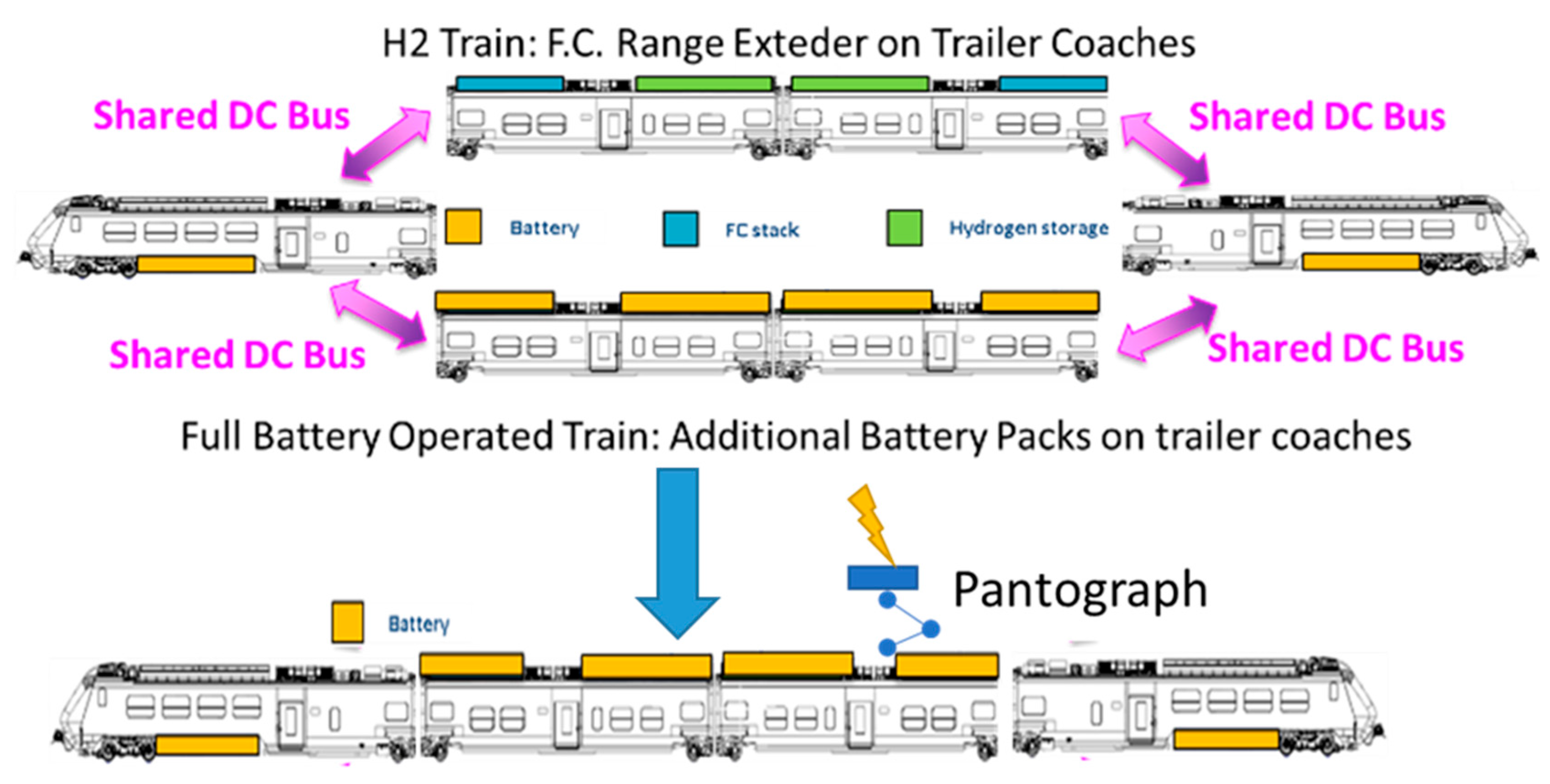
As visible in
Figure 1 both layouts substantially share the electric traction powertrains that are installed at the extremities of this fixed/articulated composition. So, both solutions share traction equipment, power converters and a part of the battery storage that for the hydrogen powered solution is used as power buffer for fuel cells[
30].For design purposes the investigated train is substantially similar to the BEMU version proposed by manufacturer in 2021[
27] but at the same time some innovative modification has been introduced for what concern storage system, power management layout and more generally some innovative considerations regarding recharge and energy interaction with surrounding infrastructure.
For the purpose of this work, which is the verification of opportunities arising from the synergy between partial electrified lines and BEMU, authors focused their attention on two different benchmark test lines.
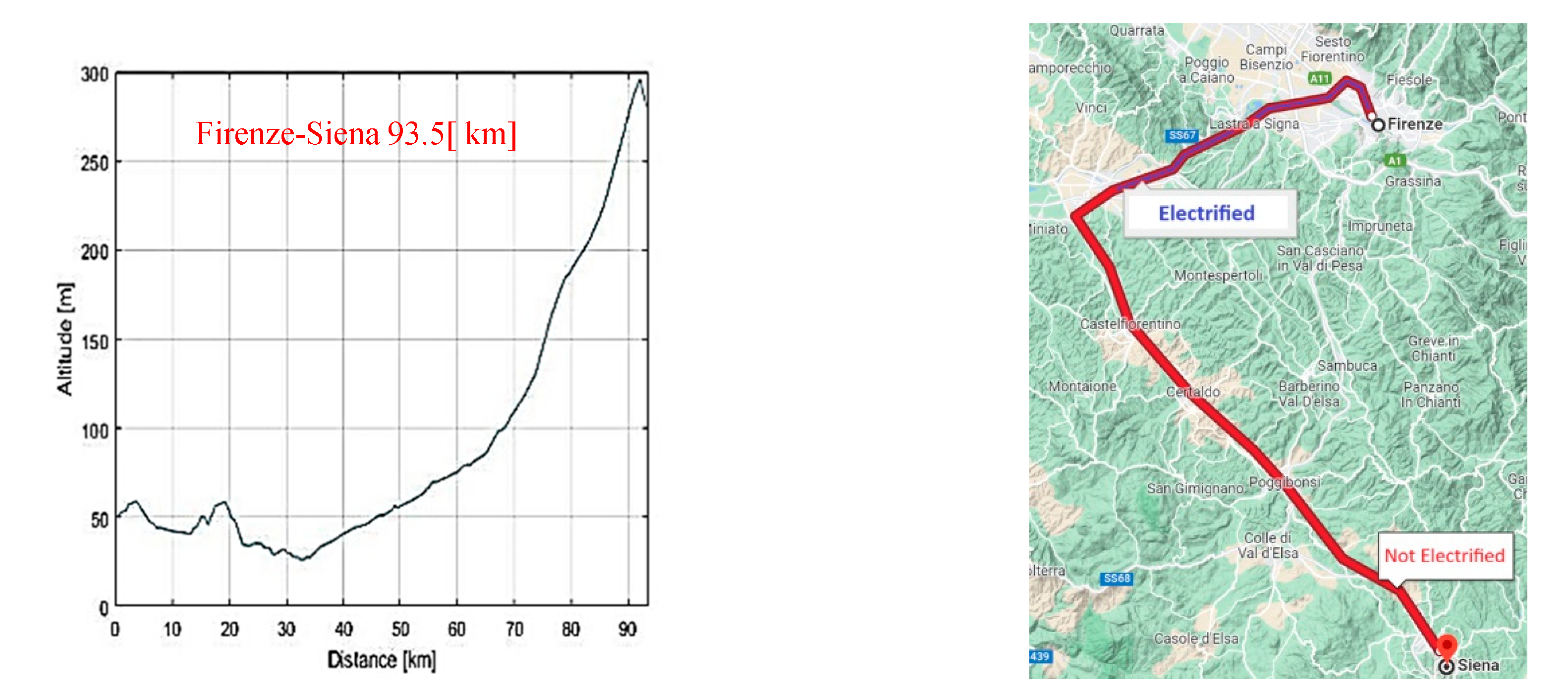
The first one is an existing partially electrified lines from Florence to Siena (about 90km of length) which is currently electrified only from Florence to Empoli (about 30km) while the remaining sections are not electrified. Main features of this line are shown in figure 2: it’s interesting to notice that the altimetric profile of the not electrified section involve a mean slope of about 4 [m/km] with a maximum slope for some kilometres of about 15[m/km], that is interesting to evaluate the stressing effect in term of required performances and opportunities arising from regenerative braking.
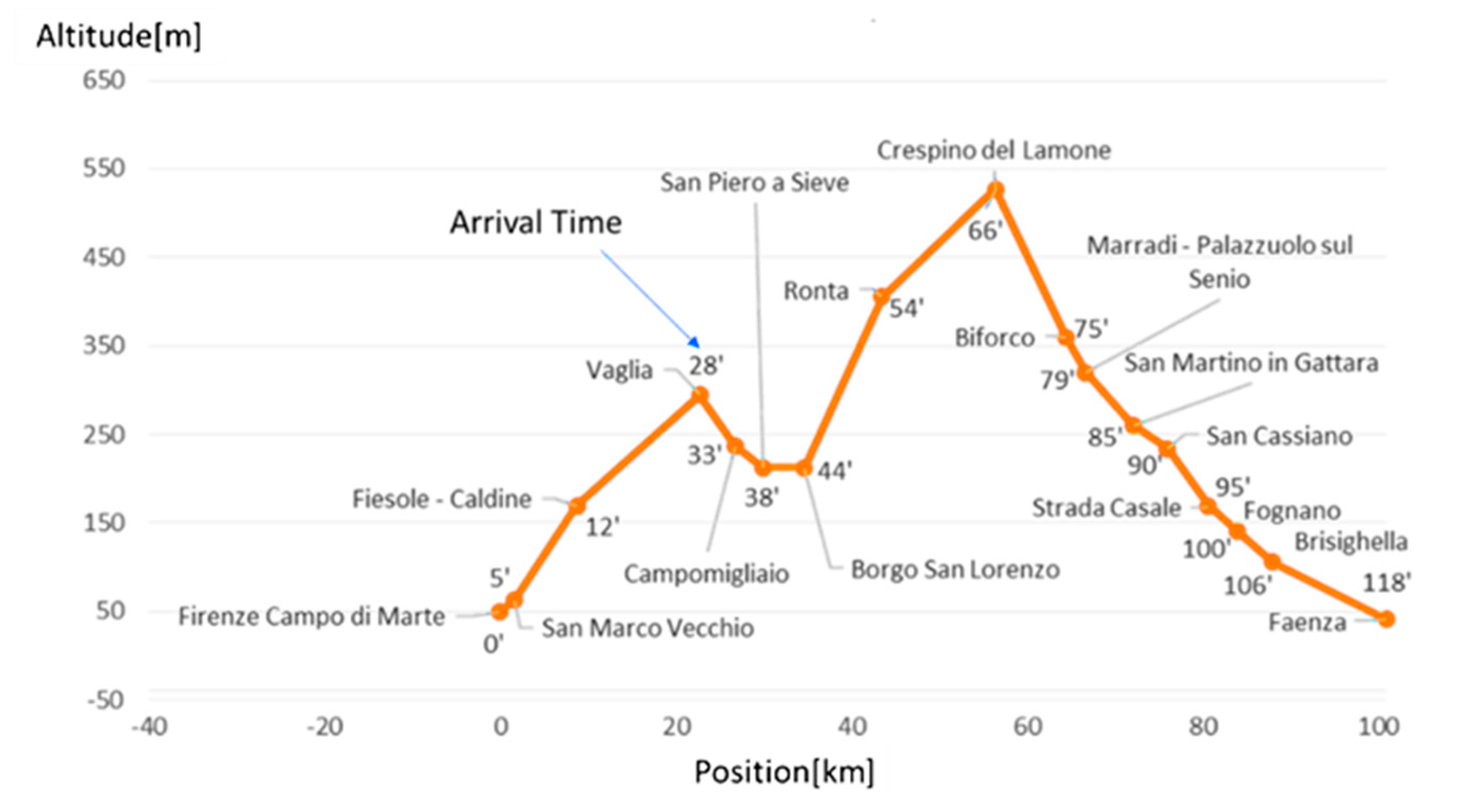
The second line is from Firenze to Faenza (length of about 100km) and it is completely not-electrified. This line is far more demanding in terms of performances respect to Firenze-Siena since the mean slope is higher (about 6[m/km]) with extended sections of tenths of kilometres in which the slope is 15-20[m/km]. This second example, which is shown in figure 3, is introduced as mission profile which is quite stressing for the current technology of BEMU. In this way it’s possible to evaluate how limited interventions on both vehicle and infrastructure technology can really improve performances and reliability of performed service. Timetables, such as the one described in
Figure 3, are taken from corresponding mission profiles adopted by trains that have been previously used on these lines.
3. Adopted Modelling Approach
Adopted Model is a further innovative extension of the model that has been recently introduced to model hybrid fuel cell rolling stock[
29,
30]. The model substantially solves the longitudinal equilibrium (1) of the convoy considering applied longitudinal forces
and different motion resistances such as
(grav. forces due to slope),
(distributed friction and aer. resistances),
(lumped motion res.),
(inertial force):
Respect to this known formulation (1), the application of traction and braking forces is evaluated considering tabulated saturations of traction and blending forces, also considering their dynamical behaviour and the effect of applied blending strategies during mixed electric and pneumatic braking. Involved power flows are calculated considering a fixed conversion efficiency of each power electronic stages of about 92% and a fixed efficiency of mechanical transmission of about 94%.
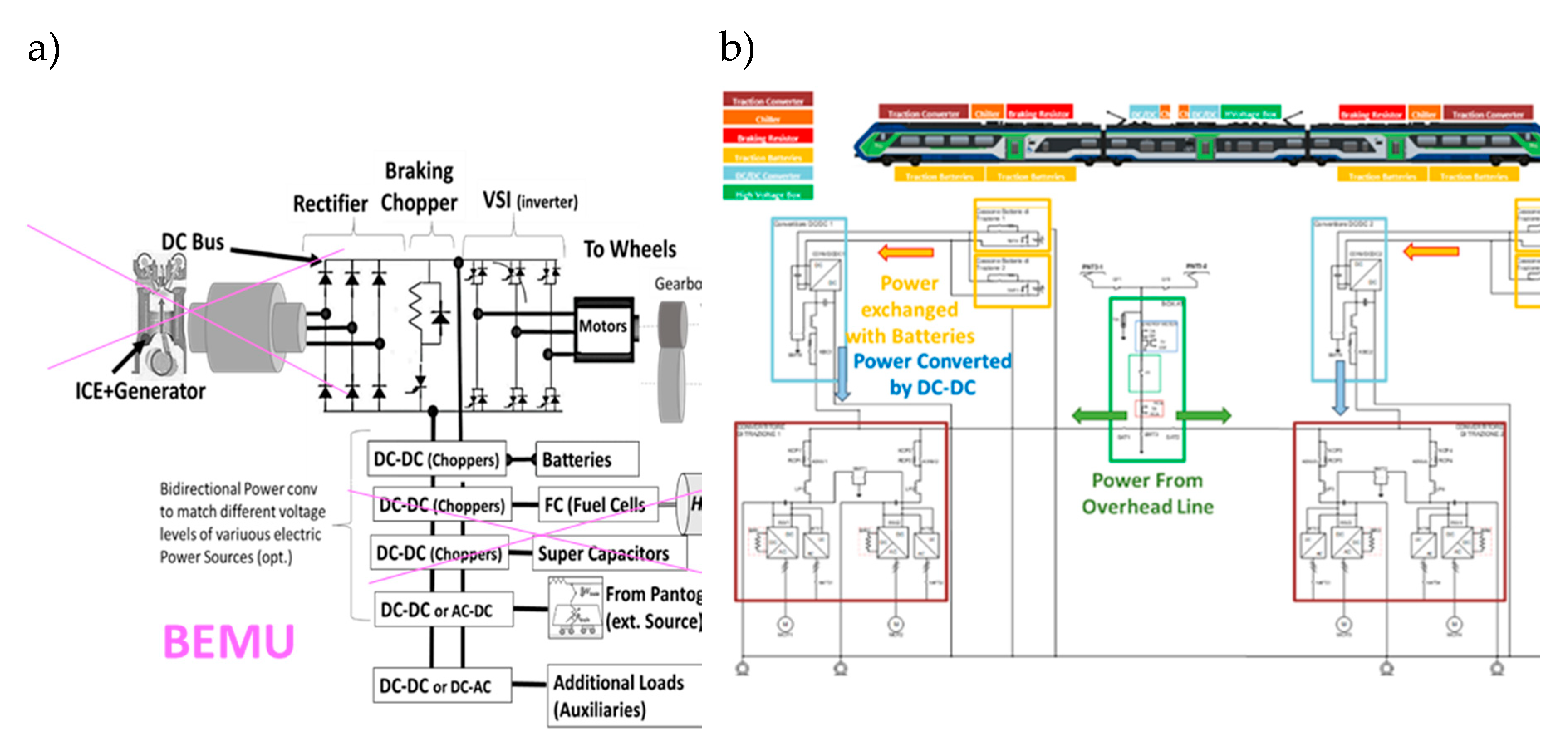
Respect to this previous model authors have introduced a generalized structure of the powertrain layout which is visible in : the system supposed to be built around a common DC Bus to which are connected directly or with an intermediate coupling stage (a power converter) all the sources and the storages that can be potentially inserted in a Hybrid or Electric Powertrain. In this way several different solutions ranging from Diesel Electric Transmissions to Hybrid Fuel Cell or Battery Electric Solutions can be modelled. For this study, the equivalent layout is shown in figure 4/a: the DC bus is connected to the pantograph and consequently to overhead line with a converter that is supposed to be equivalent to a H bridge that can be used reversible chopper under DC lines or controlled/reversible rectifier under AC lines. For the purpose of this study this power converter was designed only for DC applications to reduce encumbrance due to transformers, while the voltages levels of battery storage, DC Bus, traction equipment were considered the same. In this way proposed solutions privilege autonomy in battery mode respect to efficiency when operating under the electrified catenary.
Otherwise the scheme proposed in a preliminary presentation by the same supplier of the train[
27] is visible in figure 4/b: in this case the pantograph is supposed to be directly connected to the DC bus. So, also this layout which is a bit different can be treated as a further simplification of the same general model.
3.1. Generalized Power Management
As previously introduced the model of simulated power system is modular allowing the simulation of any combination of sources and storages that should be used to manage a multi-modal rolling stock. So, also the adopted power management system is designed to obtain a modular approach that can be easily customized and tuned respect to the chosen configuration. For this reason, authors extended the use of an approach[
31] that was originally developed and introduced for the power management of multimodal buses and trucks tested by University of Florence at ENEA laboratories of Roma Casaccia (italy).
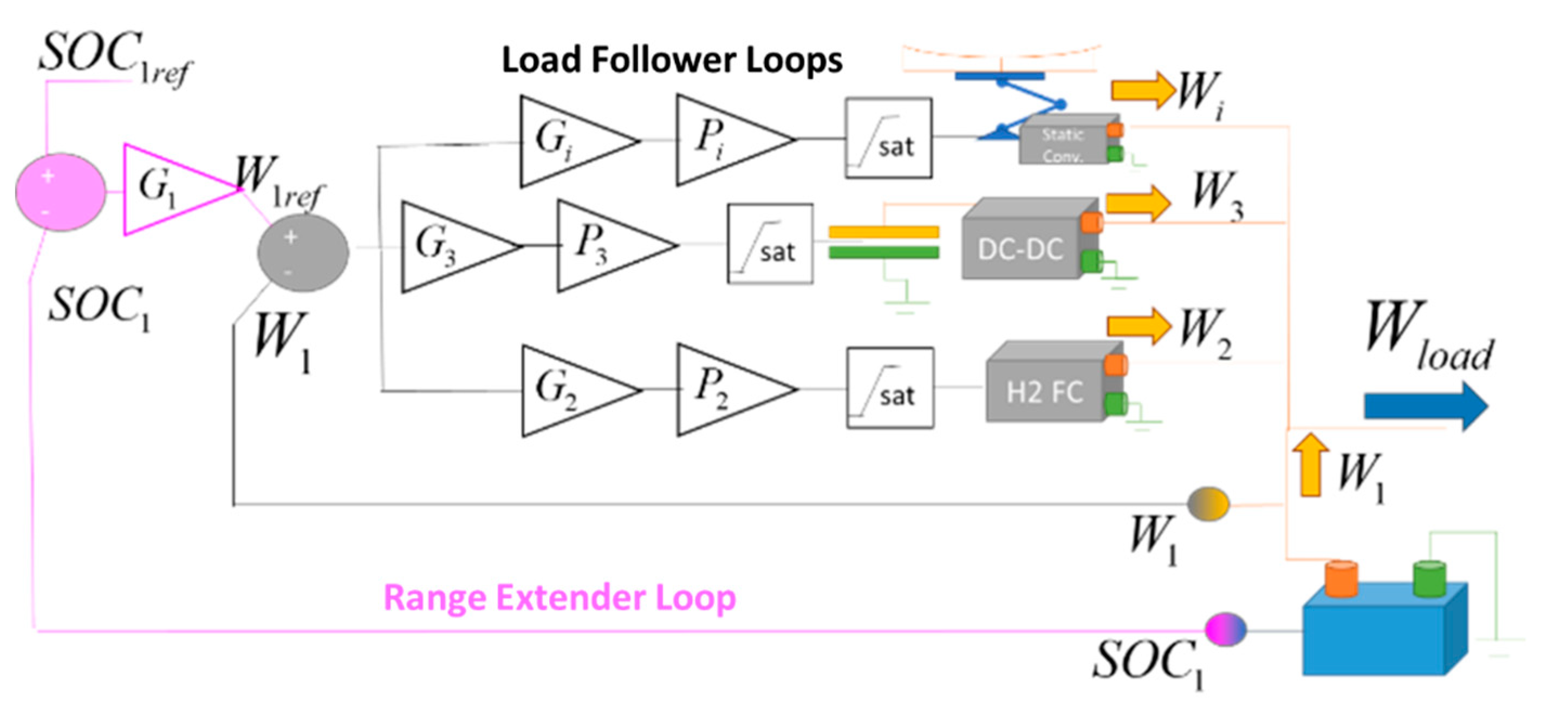
The proposed generalized layout of the control system used for power management is shown in
Figure 5: all the loads of the vehicle are supposed to be fed by a primary storage system, such as a battery. Dynamic response of the chosen primary storage is supposed to be fast enough to follow the dynamics of connected loads. Without the contribution of the other power sources and storages the power
exerted by the primary storage should be equal to the load .
.(2)
Any other source of power, for example a fuel cell, or an ICE Power-Pack, or a converter connected to an external line, can be added to the system. It is assumed that an arbitrary number of different sources or storages can be added so ( with i>1) is intended as the power exchanged by the i-th component.
Each additional storage/power can regulate to a desired value by suppling an additional power closing a loop. This loop is also called “Load Follower Loop” since the controller acting on the open loop transfer function of the i-th sourcesubstantially reject the action of the load as a disturbance so with a perfect tracking of the controller should be equal to . Further Saturations on exerted power and its derivatives should be introduced to model typical limitations of real power sources such as example an irreversible behaviour (can be only positive as example for an ICE) or a limited dynamic of response.
For an arbitrary number of additional power sources, if the simulated conditions are not able to excite any modelled non-linearity of simulated components, the response of the system can be represented in terms of transfer functions(3),(4) that are relatively easy to be tuned using conventional adopted for loop shaping.
Shaping of load follower loops, performed by tuning transfer functions can be used to adjust the way in which power fluxes are generally managed between different sources. However also the value of accumulated energy in the first storage must be stabilized. For this reason a second external loop called “Range Extender” is implemented: by regulating desired power flow it is possible to stabilize within an acceptable interval the SOC (state of charge) of the first storage system.
This loop is called “Range Extender” since the implemented functionality is quite like to the range extender approach used for hybrid road vehicle in which vehicle battery is periodically recharged according to SOC level of the battery to increase autonomy[
32].
For what concern the controller
of the range extender loop non linear controller should be better suited respect to linear one, since the desired behaviour of
is nonlinear and influenced by different considerations related to expected life and reliability of the recharged battery. However for the purposes of this study it was adopted a nonlinear polynomial load described by (5): the battery can be recharged in order to keep
within a minimum(
) and a maximum level(
) also power flows are limited in an interval between two extreme values (
,
). In this work the value of the exponent
n is equal to 2.
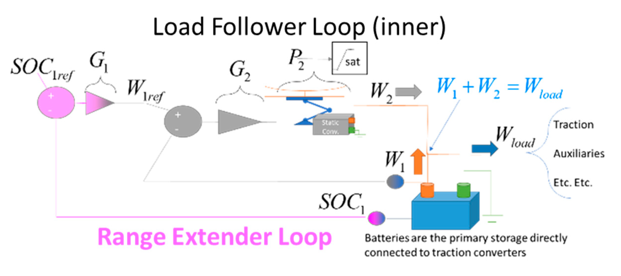
The resulting nested control system is quite flexible and easy to be tuned since higher gains of will involve a bigger contribution of the i-th source to the balancing of the vehicle loads. Otherwise by reducing the nonlinear gainis possible to increase the amount of power and energy fluctuations that should be compensated by the primary storage/battery. In this way acting on controller gains is also possible to perform bump less transitions between different operational modes, a feature that should be very interesting for multimodal rolling stock. For Battery-Operated Rolling stock, the generalized layout described in figure 5 has been simplified, obtaining the scheme described in figure 6 which is considered in current study.
3.2. Planning of Mission Profiles and high-level control of longitudinal dynamics
Planned mission profiles and the way in which simulated/virtual drivers effectively control train dynamics play a key role for the evaluation of energy consumption of a train. in literature there are several examples such as the studies of Ghaviha [
33] and Nallaperuma [
34], dealing with optimization of performed mission profiles to increase efficiency and autonomy leading to a mission profile which is strongly optimized respect to the feature of a specific battery adopted along a known line.
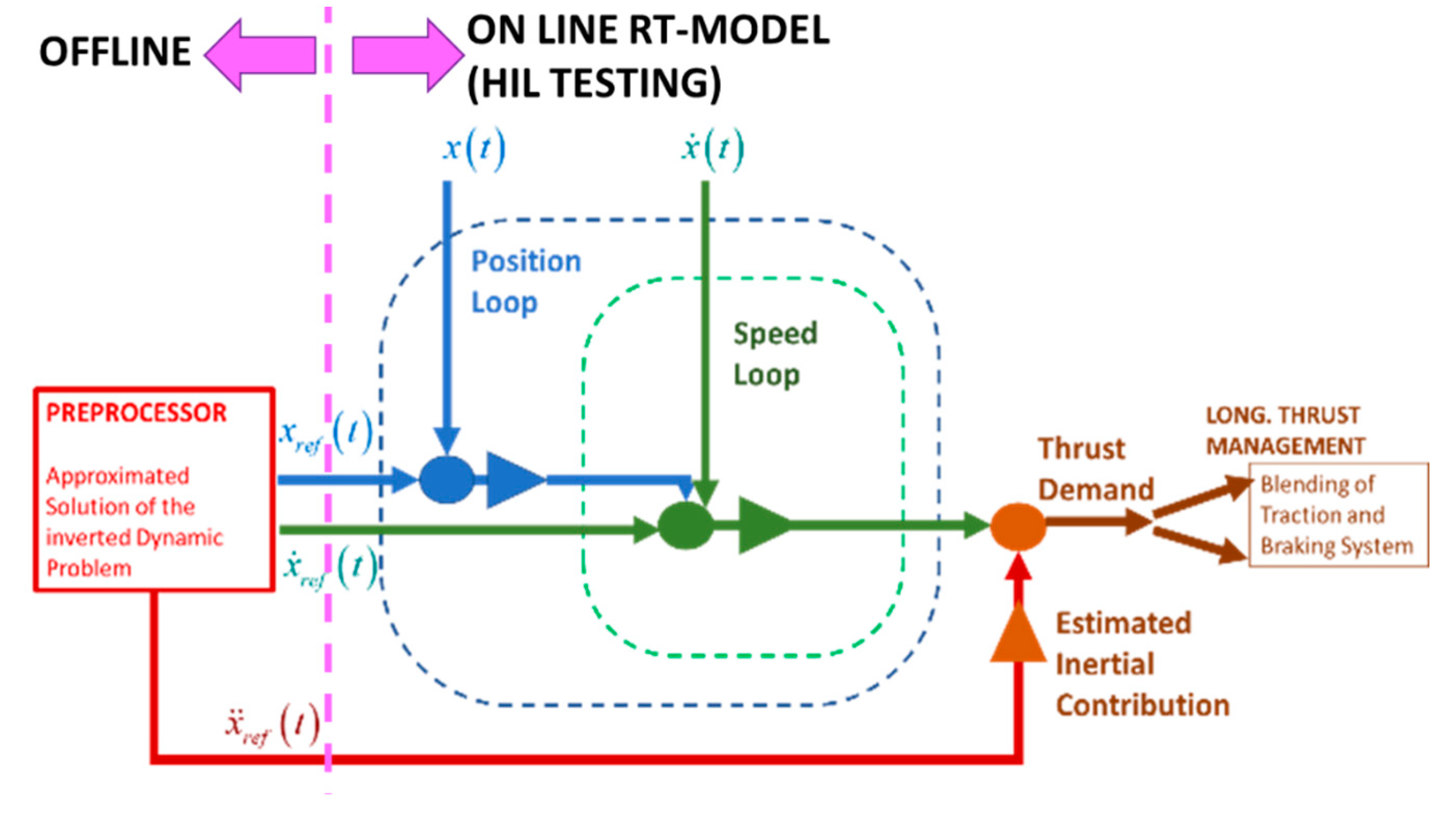
Also proposed simulation model should be designed to allow a real time implementation for an HIL (Hardware In the Loop) testing in which the model of tested system is connected to a scaled prototype of the train storage to verify mutual interactions between state and management of the storage system with traction and auxiliary loads of the simulated train as visible in the scheme of figure 7.
For a RT implementation a deterministic allocation of computational resources with a limited jitter in term of execution time is quite mandatory as verified from previous experiences related, as example, to the HIL testing of railway WSP devices[
35].
So for the purpose of this work authors adopted the approach described in
Figure 8: first an inverse dynamic problem is solved iteratively offline. Starting from a known timetable describing arrival and starting time, traveling speed profile is iteratively adjusted considering imposed speed limits for every section of the line.
Further limitations in terms of maximum accelerations, decelerations and jerks are imposed also evaluating their feasibility in terms of involved traction and braking efforts. At the end it is chosen the minimum velocity profile that assure the respect of the prescribed timetable and kinematic constraints. This approach leads to an acceptable mission profile that can be further optimized adjusting speed and acceleration profiles respect to consumed energy. Calculated trajectory, speed and acceleration profiles are then used as reference input for a closed loop control composed by nested position and speed loops aiming to regulate reference traction torques and braking of the train during the on line simulation in which a direct dynamic trouble is solved. To avoid excessive gains on both position and speed loops a model-based feedforward term is also integrated in this control loop. Resulting control can perform a precise and smooth control of vehicle trajectory avoiding unstable oscillations of performed manoeuvres that should negatively affect efficiency and robustness of the simulated system.
4. Performed Simulations and Results
4.1. Sizing of both On-board Storage and Power Management System
Sizing of on-board storage system is a part of the activities related to simulation: proposed models allow the usage of batteries with different specific energy indexes since their sizing is scaled respect to loading capability of the train in terms of available weights and encumbrances. For this study data were available from a previous investigation concerning the installation of fuel cells on the same train[
30]. For the previous study concerning hydrogen fuel cells the most important constraint was represented by available volumes for tanks, while in this one the most significant constraint is the weight that should be limited to about 11 tons. For what concern the batteries authors considered the data[
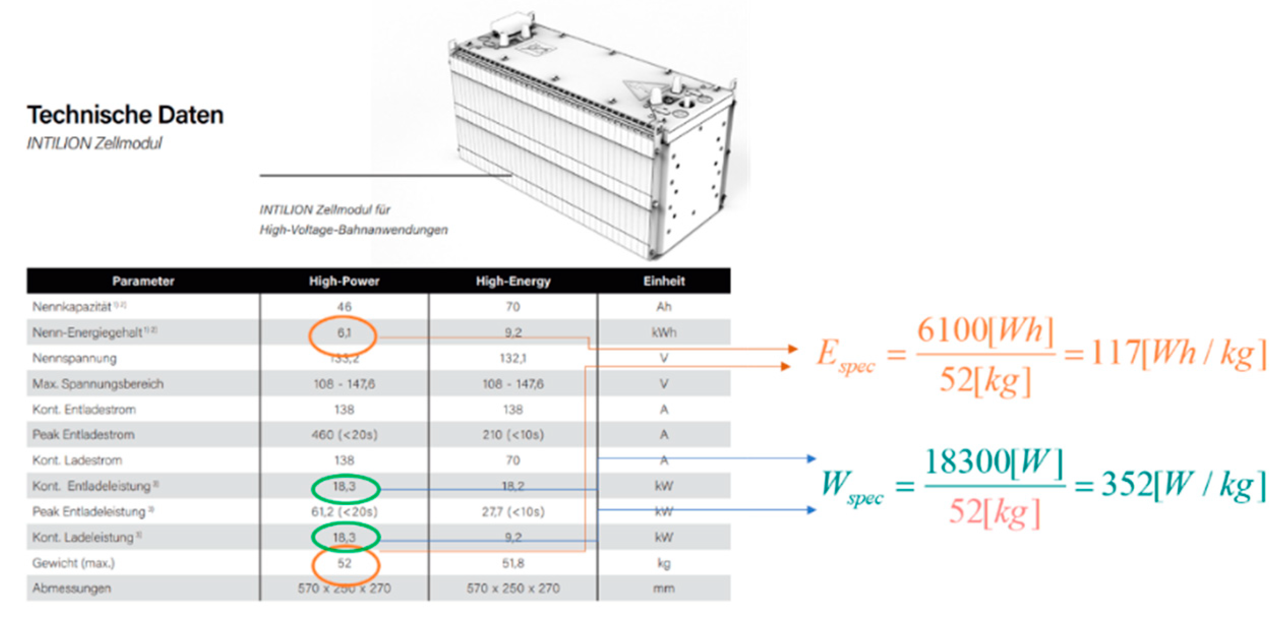
36], visible in
Figure 9 , of a recent high power battery assessed for railway applications: in which specific energy (
) and power (
) indexes are approximately equal to 117[Wh/kg] and 352[W/kg] . Homologation of the product for the railway sector is a quite important requisite since for automotive applications employed battery systems currently declare performances which are substantially doubled. The resulting size of the storage is about 1[MWh] as visible in
Table 4. High power batteries have been chosen, since a maximum charge rate of 3C (three times the nominal power of the storage) which implies in theory, a complete recharge in 20minutes. All these data are coherent with the increased performances achieved as example by BEMU[
37] that achieved the record of autonomy in Berlin (224km). These specifications are quite useful for proposed application since a battery with high charge rates support an extensive use or regenerative braking performed by the traction system whose main data are also described in table 4.
Also on partially electrified lines, a high charge rate allows a fast recharge under relatively short, electrified sections. However fast recharge of batteries cannot exceed limitations regarding the maximum power that can be collected from a 3kV DC line using a standard pantograph. In this way the system is designed to be fully interoperable with the energy infrastructure as standard EMU without the need of any special power-station, pantograph or other interface dedicated to recharge. These limitations, also described in table 4, are prescribed by interoperability specifications[
38] and by corresponding applicable standards[
39].
Power management system previously described in
Figure 6 was then calibrated adopting the set of parameters described in
Table 5: gains of the controller
G1 as described by (5) has been calibrated to fully exploit the features of the proposed battery. Allowable state of charge
SOC1 was reduced to a range between a minimum value
SOC1min equal to 0.2 and maximum one,
SOC1max, of 0.85. Value of
SOC1min was chosen to assure ae reasonable margin of robustness against battery aging also assuring a reasonable amount of backup power in case of unpredicted or excessive energy consumptions. The value of
SOC1max was decreased to 0.85 to assure a reasonable safety margin respect to the risk of potentially dangerous over voltages to which the battery can be subjected during regenerative braking. More generally the reduction of the maximum depth of discharge to about 65% and the exploitation of a mid-region of the OCV curve of chosen cells is in in favour of an extended life and reliability of the storage system, mitigating accelerated aging effect due to high recharge rates. This choice is confirmed by current technical literature. LTO, NMC or LiFePO
4 Lithium cells are conventionally indicated as well-suited for railway applications and there are several studies related to the way of increasing battery life and reliability due to high charging rates. Some studies focus their attention to the maintenance of restricted range of temperature of the lithium cell that a good kinematic of electrochemical reactions without compromising its thermal stability: even for LiFePO
4 cells [
40] that are claimed to be very stable for a thermal point of view, for a fast recharge is suggested to operate within a limited range of SOC to improve efficiency of fast charge and discharge cycles avoiding high levels of SOC where a minimal overvoltage of about 0.1V can dramatically reduce the predicted life of the cell. Also, for LTO cells which are the more extensively especially for high power storages, recent publications[
41] confirm that a reduction of the maximum DOD (Degree Of Discharge) to 60-70% substantially maximize the life of the cell especially for high power/current cycles. Also, for NMC cells[
42] a substantial increase of expected life with fast charging can be obtained decreasing the maximum SOC to values between 0.8 and 0.9.
Finally, an interesting aspect is related to balancing of cells that are assembled in the battery, cell unbalance is one of the major causes of aging of storage systems, since unbalancing systematically accelerated the degradation of some cells that unevenly loaded respect to the ones. Unbalance and consequently accelerated differential aging of cells is associated to differences in terms of voltages measured on each cell which also corresponds to a dispersion of SOC values of cells that in theory should be charged in the same way. This phenomenon is often self-accelerating since degraded cells exhibit a lower capacity that further increase their voltage fluctuations respect to the other cell that are subjected to the same current. It can be easily demonstrated that the behaviour of the system is much more stable respect to unbalancing when the derivatives of OCV(Open Circuit Voltage of the cell) respect to SOC are lower. If the value of SOC is restricted to a range between 0.2 and 0.85 the behaviour of OCV vs SOC is quite flat reducing corresponding derivatives and then the sensitivity against unbalance of cells. For this reason, also research papers[
43] that investigate the negative effect of fast charging in terms of battery unbalance, suggest the adoption of a reduced range of allowable SOC values as suggested in this work.
So, it can be concluded that chosen parameters of G1 controller are quite optimal to extend the leife of proposed batteries against fast charging. For what concern the second regulator (G2 in the scheme of figure 6), it was supposed a simple PI (proportional controller) with a high proportional gain and a very small integral one (1/100 respect to the proportional one) that assure a good tracking of required battery power calculated by the external range extender loop (G1).
4.2. Simulation of the Firenze-Siena Line (Partial Electrified line)
Authors performed an extended campaign of simulation for what concern Firenze-Siena line which confirmed the feasibility of proposed solution. Some interesting results are shown in
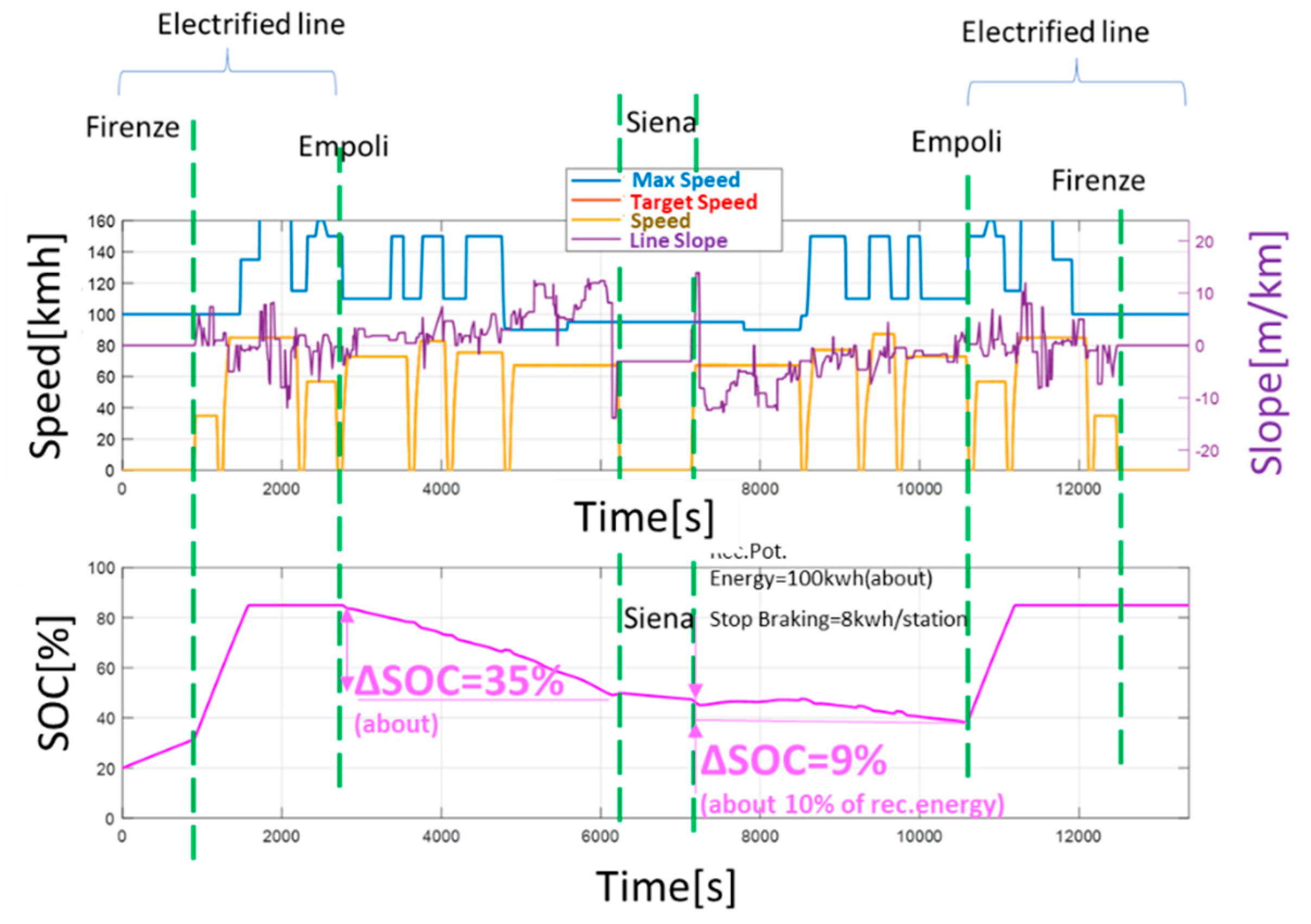
Figure 10: in this simulation it’s supposed that the train starts in the terminus station of Florence with a nearly to depleted battery (a minimum state of charge of 0.2). Then the train lift his pantograph starting to feed on board system in parking mode. Since it is supposed the usage of a standard DC pantograph under a 3kV DC catenary, collected power in standstill conditions is limited to no more than 200[A] (about 600kW). Considering a feasible consumption of auxiliaries of 120kW (30kW for each articulated carbody of the train), the remaining power to recharge on board batteries in parking mode is relatively small, so the resulting recharge of the battery is quite slow. This phase which is supposed to be about 15’ should be quite important in real operating conditions, allowing a pre-heating of cells that typically increase their reliability respect to fast charging and discharging rate.
As the train start, as visible in figure 1 the recharge rate drastically increases because the maximum value of current that can be reasonably collected from a 3kV DC line is about 6MW. In these conditions considering the size of the installed battery (1MWh) and maximum traction loads (no more than 1MW in realistic conditions), pantograph is largely capable to collect the power need for a fast recharge without penalizing traction performances. This is a direct consequence of the reduced size of BEMU trains that are usually adopted for local passenger trains. Looking at generated kinematic of the mission profile, it is clearly noticeable that the simulated train can reproduce almost perfectly both imposed timetables and trajectories which are relatively smooth respecting not only speed but also imposed limits on accelerations and jerks. The capability of reproducing also the duration of stops in intermediate stations is fundamental to calculate energy consumptions of auxiliaries during train stops. Recharge along the electrified line is concluded in about one third of the available time (about 700-800 seconds) so it can be concluded that the same recharge can be performed also admitting a maximum recharge rate of 1C, paving the way to the implementation of a predictive logic able to reduce the recharge rate according to foreseen mission profile.
As the simulated mission continues in the not electrified section it can be observed small fluctuations of the SOC associated to regenerative braking on batteries. To further verify the robustness of proposed solution is also considered the absence of an intermediate recharging infrastructure in the station of Siena, so consumptions of auxiliaries produce a constant discharge rate corresponding to about 0.12C, clearly explaining how consumption of auxiliaries should be important for the evaluation of autonomy in real operational conditions. When the train left Siena to return to Florence, consumption under the not electrified section of the line is clearly lower, since the extended usage of regenerative braking allows an efficient recover of potential energy in the downhill section of the line. Finally, when the train reachs the electrified section in Empoli the battery is completely recharged reaching the station of Florence with a full charged battery.
This simulation clearly demonstrates that in this scenario in which the length of the electrified section is about one third respect to the total length of the line, the system is substantially stable from an energetic point of view also considering the aging of the cells since the minimum level of SOC at end of the not electrified section is still about 0.4(40%). This robustness is also granted by the extended application of regenerative braking that assure an energy saving of about 100kWh compensating at least a part of the consumption of auxiliaries under the not electrified section which are evaluated to be equal to about 250kWh. This impressive value clearly gives an idea of the importance of auxiliary loads in assessing the real autonomy of a BEMU.
Looking to simulated mission profile is also possible to perform a cautious evaluation of expected life.
During a day of service (about 10-12 hours of service a day, about 500-600km/day ) about a1.6-1.7 FCE (Full Cycle Equivalent) of battery life are expended. Even considering a granted life of 2500 cycles which is considered the baseline performance for automotive batteries subjected to fast charging the expected life of the storage is supposed to be more than 4-5 years of uninterrupted service (corresponding to a mileage of about 900000km). This value is very cautious because some of the sources cited in this work[
41] claim an expected life for LTO cells properly protected (good thermal management, reduced DOD) an expected life 1-2.5*10
4 FCE which is substantially 4-10 times higher respect to the considered one. In this work reduced DOD is supposed but the second condition (perfect thermal management) is difficult to be verified in a simulation environment. However the same testing campaign [
41] also consider a baseline reliability of more than 4000-5000 FCE(“cold cells” at 25C° with 5-10C charging currents) which is still able to assure an expected life of the battery of more than 8-10years of continuous service.
So, it can be concluded that in terms of expected life of the battery pack proposed solution is satisfactory but that a more precise evaluation involve a specific electro-thermal study that will be the object of ongoing activities.
4.3. Simulation of the Firenze-Faenza Line
As previously introduced this second line is longer, has a more demanding altimetric/mission profile so it can be considered a benchmark test case for the proposed rolling stock.
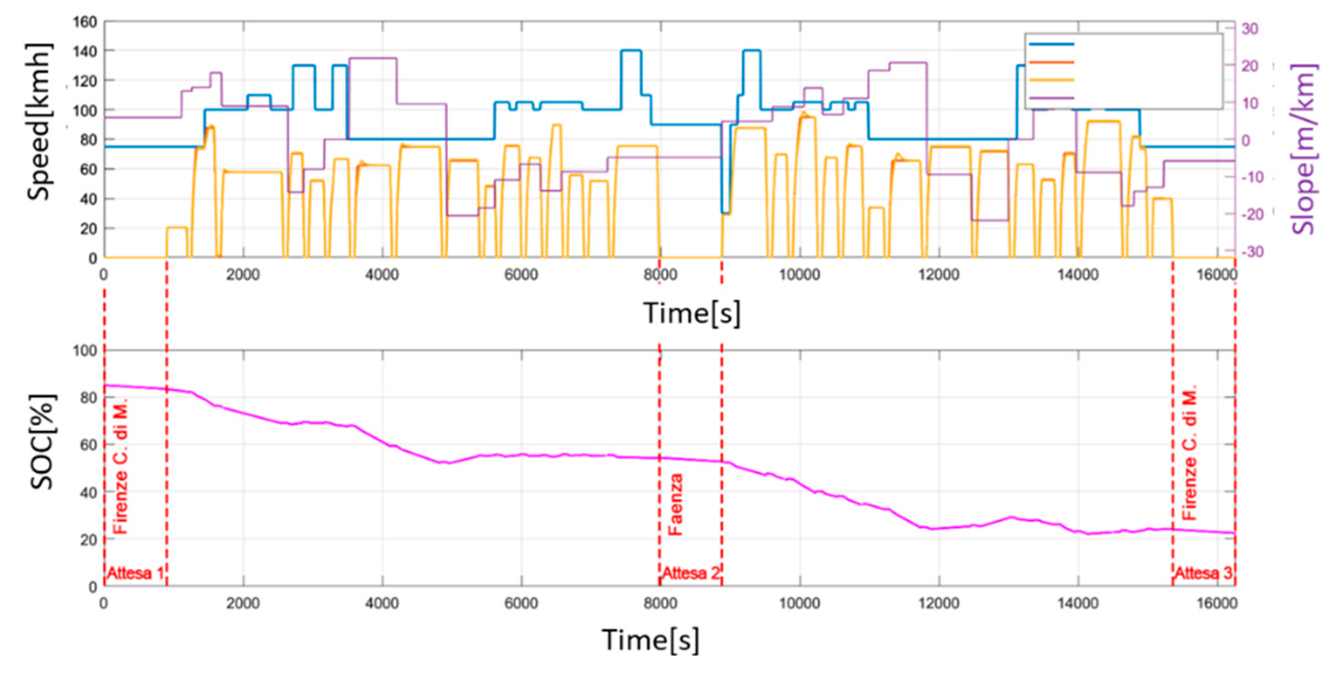
As in the simulation of Firenze-Siena, for this line is performed a round trip (from Florence to Faenza and the return to Florence) without any intermediate recharge. Also, the train is stopped at each terminus station for 15 minutes considering consumptions of auxiliaries of the train. This mission cannot be completed using the high-power battery that was adopted for the benchmark test run on Firenze-Siena line since estimated energy consumptions are about the 150% of the maximum quantity of energy that can be stored on the train.
So, a minimum level of specific energy
equal tool 180Wh/kg (1.5 times higher than the adopted one) is needed to complete the mission. This is not an unfeasible value for a railway application since, as example, looking to the catalogue of figure 9 [
36] an Intilion™ high energy module (assessed for railway applications) can reach this desired performance which is also aligned to specifications of batteries that are currently used for many automotive applications. An example of simulation results obtained considering the installation of this high energy module (corresponding to a size of about 1.65 MWh) is shown in
Figure 11: It's clearly noticeable that the final value of battery SOC is quite low (almost exactly the minimum one 0.2/20%) so flexibility and robustness of this solution respect any uncertainty should be a bit critical: maximum allowable charge and discharge rates of a high energy modules are lower, so a static recharge of about one hour should be considered. Finally, the high energy module should be a bit more sensitive to cycle aging respect to the high power one especially for what concern fast charging and loading peaks associated to regenerative braking or to train acceleration.
4.3.1. Simulation Scenario with a partial electrification of the line
A partial electrification of the line can be introduced to allow a discontinuous recharge of the train along the line. The choice of electrified sections and the way in which power is managed can be the object of different optimizations that are briefly listed in some review works as the one performed by Fedele[
44]:
Feasibility and Robustness of the proposed solution clearly depends on the capacity of the on board batteries of providing the desired autonomy along not-electrified sections. So, the distribution of partially electrified sections should tendentially minimize the maximum value of required energy to travel along the most demanding section in which the train should use batteries.
Electrification should take count of local availability of power sources and of the orography of the line to minimize construction and maintenance costs.
Partial Electrification should be placed in sections of the line in which higher power flows are statistically recorded such as railway stations where higher accelerations and decelerations of the train are statistically more common. Also, the slope of the line is another factor that should contribute to increase energy consumptions.
Duration of a dynamic recharge under the catenary is limited by the length of the electrified section. So, the duration of the recharge can be inversely proportional to mean train speed. It’s more convenient to electrify sections of the line in which the mean speed is not very high. This consideration should consider that in pure standstill conditions the amount of power that can be collected is about one tenth.
Accepting these four criteria authors decided to adopt the configuration described in figure 12 and in table 6: both the two terminus stations of Firenze and Faenza are connected to electrified lines with high traffic intensities. For this reason, a recharge in standstill conditions inside both stations is possible at almost no cost if a conventional pantograph is employed. Also, the extension of the electrification of few kilometres outside the station is relatively unexpensive. Finally, it is just outside the terminus station that the train stock is accelerated so a relevant amount of power and energy should be transferred respect to the length of the electrified section. For all these reasons the electrification of the two-terminus station is considered as an imposed constraint evaluating only the possibility of optimizing the extension of the electrified section along the line. Clearly if the extension of the electrified section is too long (over ten-fifteen kilometres) additional costs infrastructural costs especially for power-stations should be evaluated.
Considering the previously calculated ratio between energy stored with high power storage and the energy consumption to complete the mission an intermediate charging section should be enough to prolong the autonomy of the train. An optimal positioning should correspond a distance which is about halfway between the two stations where the consumed energy for both traveling directions is almost a half of the total one of consumed energy can be performed directly locking the SOC and SOC derivatives calculated in the preliminary simulation of figure 11 where all the energy needed to manage the mission is taken from the onboard battery.
As visible in
Figure 12, the optimal position of this intermediate electrified station is different according to the traveling direction of the train: if the train is starting from Florence the optimal position for a recharge station will be around Borgo San Lorenzo. Otherwise, if the train is returning from Faenza a good location should be approximately between the stations of Biforco and Marradi.
The first location, (around Borgo San Lorenzo) is also the most favourable in terms of construction and maintenance costs: the electrified section should be located in a flat, easily accessible, area in the Mugello valley between Campomigliaio and Panicaglia, where also connection to power grid is relatively easy since in the same valley the local line is very near to power stations of the high speed railway line Firenze-Bologna and to the high voltage electro-duct from Florence to Bologna. Also, near Borgo San Lorenzo, as visible in figure 12 there is the intersection with another not electrified line also coming from Florence through Pontassieve, so an electrification in this area should be synergic also for this second railway line.
So according to logistic evaluations it was preferred the first location which is not optimal for the return trip. To partially compensate a choice which penalizes on board batteries during return trips from Faenza, the electrified section from Faenza was extended a bit (a further increase of length or the insertion of a second intermediate recharge was considered potentially much more expensive). The length of the electrified from Florence station was minimized since a further extension was not substantially useful.
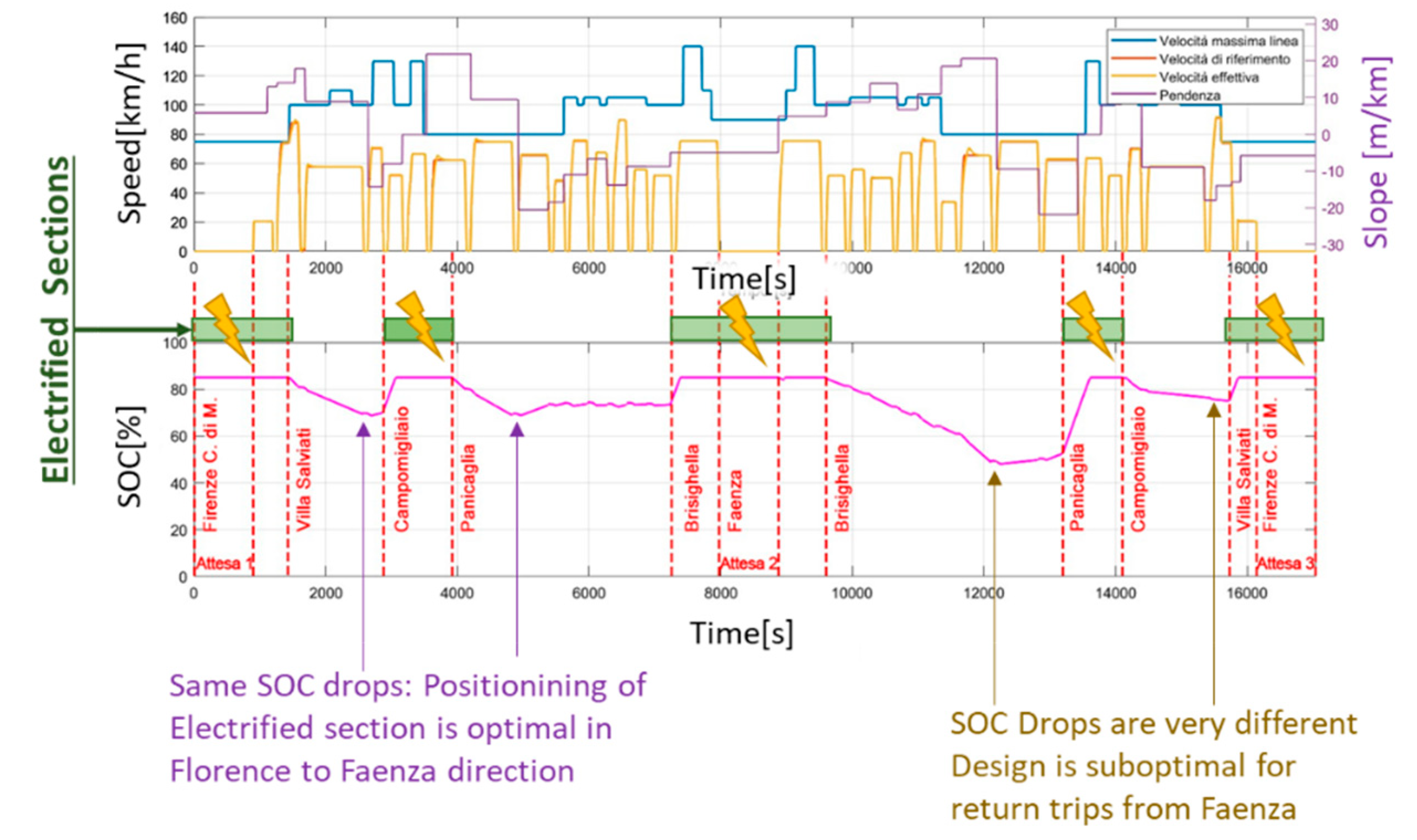
A complete simulation involving a roundtrip using high power batteries is then repeated. Some results are visible in
Figure 13: the train can complete the roundtrip mission with a maximum DOD (Degree of Discharge of the Battery) of about 35% (0.35); at each terminus station (Firenze or Faenza) and even at the end of the intermediate recharge section the battery is completely refilled; also required So the performed system is stable from the energetic point of view. For the traveling direction from Florence to Faenza the maximum DOD is about 18% and it’s almost equal for the two not electrified sections of the line. So, in the direction from Florence to Faenza, the proposed layout is almost ideal. For the return trip (from Faenza to Florence) the maximum DOD is almost doubled (about 35%).
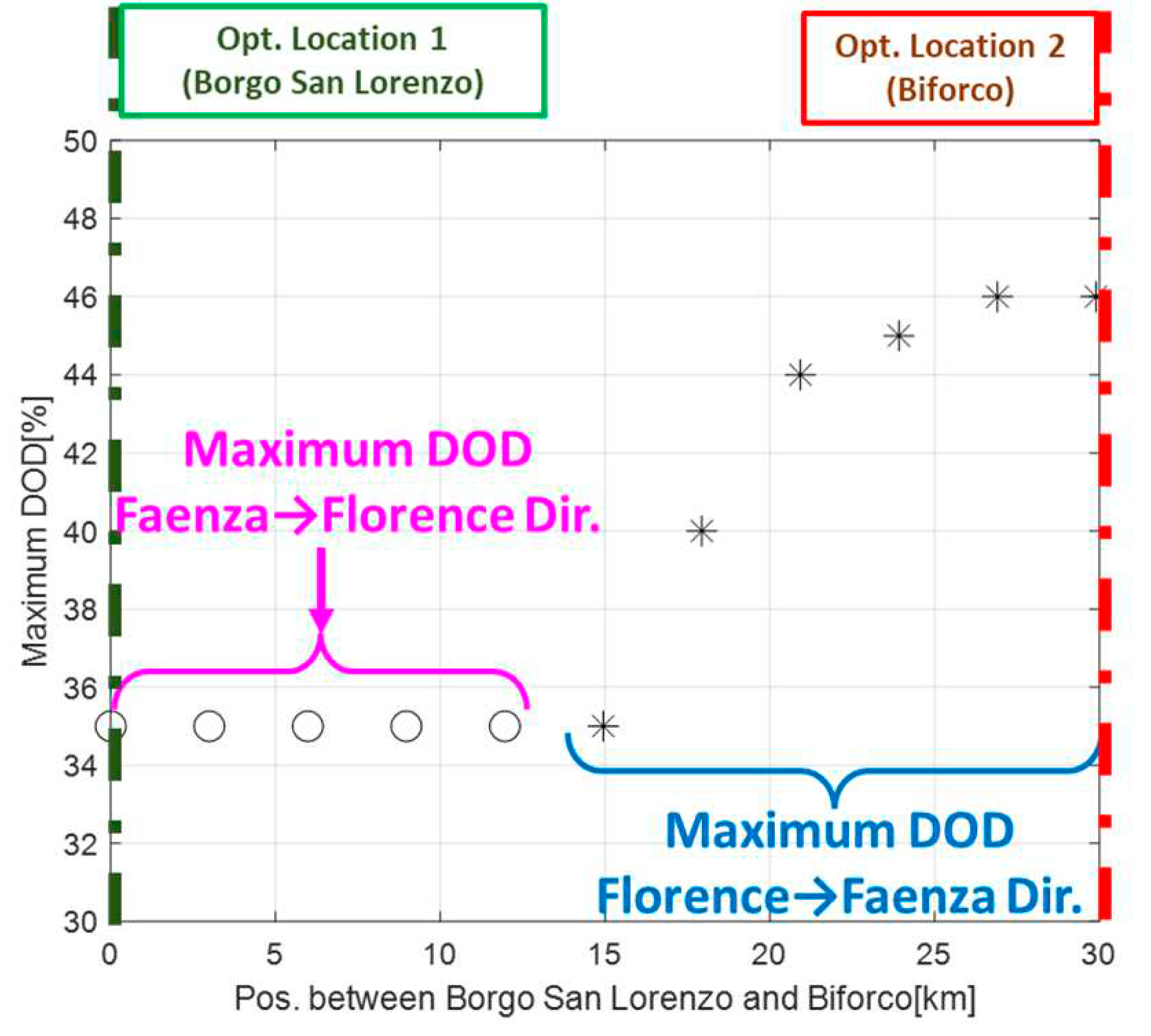
For this reason, a further optimized by simply imposing a shifting of the positioning of the intermediate electrified section between the two optimal locations, the first one, at Borgo San Lorenzo, and the second one at Biforco. For each configuration it is calculated the maximum DOD of the battery measured along a roundtrip mission: as shown in
Figure 14, there is no configuration that minimize the maximum DOD under the 35% the minimum value recorded in the chosen nominal configuration. As the shift of the intermediate electrified section is increased the maximum DOD recorded when the train is traveling from Florence to Faenza increases to a maximum DOD of about 45-46%. So, it can be concluded that chosen position of the intermediate section is also optimal to minimize the maximum DOD of the battery.
4.3.2. Evaluation of Collected Currents on Added Electrified Sections
Using the power profiles, simulate with the previously described model was also possible to evaluate the entity of collected currents by the adopted pantograph under the electrified sections of the line. Aim of this calculation is not a complete simulation of the electrical layout but only a rough evaluation of the effect of estimated losses considering a simplified bilateral layout with known distributed resistances along the line and some feasible value of lumped resistances of power stations. For the purpose estimation it was performed considering a minimum and a maximum power capability of the infrastructure whose data have been taken from previous research activities[
45]. As shown in
Figure 15, even considering losses along the catenary collected currents are compatible in both scenarios with limits imposed by regulations in force. Also, the overall efficiency of the fixed infrastructure in terms of dissipated energy due to internal electric resistances is quite high (over 90%). Peaks of collected currents have a relatively short durations so there is a clear indication that the same mission profile can be performed lowering the max recharge rate of batteries to at least 1-2C further increasing feasibility and reliability of proposed solution. Finally, since there is no inversion of collected currents there is no need of reversible substations, also reducing cost and complexity of the fixed infrastructure. The study can be further improved considering the interaction of multiple battery-operated trains with the infrastructure.
Table 7.
Parameters of the Simulated.
Table 7.
Parameters of the Simulated.
| |
Heavy Catenary[45] |
Light Catenary |
| Distributed impedance along the line |
0.05[Ώ/km] |
0.1[Ώ/km] |
| Output Impedance of Power Station |
0.09[Ώ] |
0.36 |
| No Load Voltage (Max Voltage of Power-Stations) |
3700[V] |
3500[V] |
Conclusions
In this work author has introduced an example of complete model that can be used to perform a preliminary sizing and evaluation of a BEMU considering different mission profiles. Proposed simulation tools, methodologies and studies focused their attention on the generality of the proposed approach, considering complex mission profiles in which the behaviour of the system is stressed by complex altimetric profiles and by high consumptions of auxiliaries. Proposed models are applied to two different mission profiles: the first one (Firenze-Siena) corresponds to a mission profile in which BEMUs are used to extend the service outside an electrified line. The second one (Firenze-Faenza) regards a service on a mountain line in which some short, electrified sections are deliberately designed to sustain autonomy and reliability of BEMUs.
Both simulated scenarios demonstrate potential advantages arising from the synergy battery operated rolling stock and the possibility of performing a dynamic recharge along electrified sections whose length and positioning can be optimized. Ratio between electrified sections and not electrified ones is clearly depending by performances of adopted batteries in terms of specific power. For the state of the art, high power batteries considered in this work the length of electrified sections respect to not electrified ones can be about one third maintaining high level of safety margin respect to uncertain loads, variable mission parameters, aging of batteries or other derating imposed as example by BMS (Battery Management System). Relative extension of electrified sections can be further reduced considering technological evolution of storage systems.
Cost of this partial electrification must be evaluated for every application scenario with a detailed study that is not the object of this work; however, proposed solution by using standard pantographs and catenaries introduces a considerable saving in terms of dedicated infrastructures respect to a dedicated recharge. At the same time recharge in standstill conditions is potential drawback of the proposed solution. Standard pantographs are designed for a limited power collection especially on DC lines. For a short BEMU like the proposed one, collected power is still able to sustain a slow recharge in standstill conditions, but for longer compositions such as a long, battery-operate, freight train power collected in standstill conditions should be insufficient especially for DC lines where max voltages are limited to 3kV. A possible alternative is represented by systems dedicated to standstill recharge of the system such as wireless inductive power transfer systems that have been previously proposed to implement railway parking recharge functionality[
47].
List of Adopted Symbols
|
Longitudinal Efforts (traction and braking) applied to the whole railway composition |
|
Motion Resistances due to the altimetric profile of the line (gravitational forces) |
|
Distributed Motion Resistances due to internal Friction and Aerodynamic Forces |
|
Lumped Motion Resistance due to line geometry such as curves (as example) |
|
Inertial forces calculated considering the total equivalent inertia of the train |
|
Power exerted by the first on board storage system. |
|
Total Power required by traction loads and auxiliary ones. |
|
Power exerted by the i-th on board storage or power source. |
|
Transfer functions of the i-th control loop and transfer function of the i-th plant |
|
Desired/reference power profile for the first storage |
|
,
|
Maximum and minimum values of power exchanged by the first storage. |
|
State of Charge of the first storage and corresponding allowable maximum and minimum values |
|
Exponent of the control law described in equation (5) |
|
,
|
Specific Energy and Power of adopted batteries |
|
Nominal power size of the battery |
Acknowledgement
This study was carried out within the MOST – Sustainable Mobility National Research Center and received funding from the European Union Next-GenerationEU (PIANO NAZIONALE DI RIPRESA E RESILIENZA (PNRR) – MISSIONE 4 COMPONENTE 2, INVESTIMENTO 1.4 – D.D. 1033 17/06/2022, CN00000023). This manuscript reflects only the authors’ views and opinions, neither the European Union nor the European Commission can be considered responsible for them.
Conflict of Interest
Authors certify that there is no actual or potential conflict of interest in relation to this article.
References
- European Alternative Fuels Observatory https://alternative-fuels-observatory.ec.europa.eu/transport-mode/rail#:~:text=Regarding%20main%20lines%2C%2060%25%20of,is%20running%20on%20these%20lines.
- Distribution of Electrified lines in Germany according Stadler https://www.stadlerrail.
- Magelli, M., Boccardo, G., Bosso, N., Zampieri, N., Farina, P., Tosetto, A., Mocera, F. and Somà, A., 2021. Feasibility study of a diesel-powered hybrid DMU. Railway Engineering Science, 29, pp.271-284.
- Singh, K.V., Bansal, H.O. and Singh, D., 2019. A comprehensive review on hybrid electric vehicles: architectures and components. Journal of Modern Transportation, 27, pp.77-107.
- Zenith, F. Battery-powered freight trains. Nature Energy. 2021 Nov;6(11):1003-4.
- Laperrière Y, Eng P. Realize your vision with Bombardier TALENT 3 BEMU. InAPTA 2019 Rail Conference 2019 Jun 24 (pp. 23-26).
- Böhm M, Del Rey AF, Pagenkopf J, Varela M, Herwartz-Polster S, Calderón BN. Review and comparison of worldwide hydrogen activities in the rail sector with special focus on on-board storage and refuelling technologies. International Journal of Hydrogen Energy. 2022 Sep 17.
- Stobnicki P, Gallas D. Adoption of modern hydrogen technologies in rail transport. Journal of Ecological Engineering. 2022;23(3).
- Zenith, F., Isaac, R., Hoffrichter, A., Thomassen, M.S. and Møller-Holst, S., 2020. Techno-economic analysis of freight railway electrification by overhead line, hydrogen and batteries: Case studies in Norway and USA. Proceedings of the Institution of Mechanical Engineers, Part F: Journal of Rail and Rapid Transit, 234(7), pp.791-802.
- Cole C, Sun Y, Wu Q, Spiryagin M. Exploring hydrogen fuel cell and battery freight locomotive options using train dynamics simulation. Proceedings of the Institution of Mechanical Engineers, Part F: Journal of Rail and Rapid Transit. 2023 Mar 31:09544097231166477.
- ZHANG, Xinfeng, et al. (2017) Load profile based empirical model for the lifetime prediction of an automotive PEM fuel cell. International Journal of Hydrogen Energy, 2017, 42.16: 11868-11878.
- Fragiacomo P, Piraino F. Fuel cell hybrid powertrains for use in Southern Italian railways. International Journal of Hydrogen Energy. 2019 Oct 22;44(51):27930-46.
- On line report on the first service operated by Coradia I-Lint https://www.alstom.com/it/press-releases-news/2022/8/anteprima-mondiale-14-coradia-ilint-inizieranno-il-servizio-passeggeri, data accessed on 1st July 2022.
- Bosch (2023),Catalogues and tech. doc. related to high pressure tank from Hexagon™ official site https://s3.eu-central-1.amazonaws.com/hexagonpurus/website/HexagonPurus_Brosch%C3%BCre_HighPressureType4.pdf, accessed on 13 july 2023.
- Luxfer(2023), Catalogues and tech. doc. related to high pressure tank from Luxfer™ official site https://www.luxfercylinders.com/ accessed on 17 july 2023.
- Yilmaz, F., Ozturk, M. and Selbas, R., 2020. Design and thermodynamic modeling of a renewable energy based plant for hydrogen production and compression. International Journal of Hydrogen Energy, 45(49), pp.26126-26137.
- Liu, X. and Li, K., 2020. Energy storage devices in electrified railway systems: A review. Transportation Safety and Environment, 2(3), pp.183-201.
- Meehan P and Knibbe R. Decarbonising Australian railway fleetswith batteries. Australia: School of Mechanical and Mining Engineering - University of Queensland 2022.
- Frith, J.T., Lacey, M.J. and Ulissi, U., 2023. A non-academic perspective on the future of lithium-based batteries. Nature Communications, 14(1), p.420.
- Hoffrichter A, Silmon J, Schmid F, Hillmansen S, Roberts C. Feasibility of discontinuous electrification on the Great Western Main Line determined by train simulation. Proceedings of the Institution of Mechanical Engineers, Part F: Journal of Rail and Rapid Transit. 2013 May;227(3):296-306.
- Abdurahman, B.M., Harrison, T., Ward, C.P. and Midgley, W.J., 2021. An investigation into intermittent electrification strategies and an analysis of resulting CO2 emissions using a high-fidelity train model. Railway Engineering Science, 29(3), pp.314-326.
- Jakubowski, A., Karkosińska-Brzozowska, N., Karwowski, K. and Wilk, A., 2020. Storage electric multiple units on partially electrified suburban railway lines. Przegląd Elektrotechniczny, pp.158-161.
- M. Schenker and F. Kühlkamp, "Optimization Model for Operation of Battery Multiple Units on Partly Electrified Railway Lines," 2021 Sixteenth International Conference on Ecological Vehicles and Renewable Energies (EVER), Monte-Carlo, Monaco, 2021, pp. 1-8. [CrossRef]
- M. Juston, B. Vulturescu and A. Chamaret, "A statistical approach for the optimal sizing of partial electrification for battery trains," 2023 IEEE International Conference on Electrical Systems for Aircraft, Railway, Ship Propulsion and Road Vehicles & International Transportation Electrification Conference (ESARS-ITEC), Venice, Italy, 2023, pp. 1-6. [CrossRef]
- IRS 60608-1ed. Conditions to be complied with for the pantographs of tractive units used in international services published on 1.7.2019.
- Tech documents related to results of the European research project FCH2RAIL https://verkehrsforschung.dlr.de/public/documents/2022/FCH2RAIL_ProjectOverview_2022.pdf.
- Alessandro Vannucchi, La piattaforma MASACCIO di Hitachi Rail per la decarbonizzazione dei treni regionali, La Transizione Tecnologica Dalla Trazione Diesel ai Nuovi Treni a Batteria e Idrogeno, presentation performed on 29th Sept. 2021 at Convegno Webinar at Expo Ferroviaria, available for download at the official site of ANIE https://anie.it/.
- Tech data from Staedler (visited last time on 14/05/2023) https://www.stadlerrail.com/en/flirt-akku/details/.
- Pugi, L., Berzi, L., Cirillo, F., Vecchi, A., Pagliazzi, V.A tool for rapid simulation and sizing of hybrid traction systems with fuel cells(2023) Proceedings of the Institution of Mechanical Engineers, Part F: Journal of Rail and Rapid Transit, 237 (1), pp. 104-113. [CrossRef]
- Pugi, L., Berzi, L., Spedicato, M., Cirillo, F.Hydrogen for railways: design and simulation of an industrial benchmark study (2023) International Journal of Modelling, Identification and Control, 43 (1), pp. 43-53. [CrossRef]
- Pugi, L., Alessandrini, A., Barbieri, R., Berzi, L., Pierini, M., Cignini, F., Genovese, A., Ortenzi, F.Design and testing of a supercapacitor storage system for the flash recharge of electric buses(2021) International Journal of Electric and Hybrid Vehicles, 13 (1), pp. 57-80. [CrossRef]
- Tran, M.K., Bhatti, A., Vrolyk, R., Wong, D., Panchal, S., Fowler, M. and Fraser, R., 2021. A review of range extenders in battery electric vehicles: Current progress and future perspectives. World Electric Vehicle Journal, 12(2), p.54.
- Ghaviha, N., Bohlin, M., Holmberg, C. and Dahlquist, E., 2019. Speed profile optimization of catenary-free electric trains with lithium-ion batteries. Journal of Modern Transportation, 27, pp.153-168.
- Nallaperuma, S., Fletcher, D. and Harrison, R., 2021. Optimal control and energy storage for DC electric train systems using evolutionary algorithms. Railway Engineering Science, 29, pp.327-335.
- Pugi, L., Paolieri, G., Giorgetti, M., Berzi, L., Viviani, R., Cabrucci, L., Bocciolini, L.HIL testing of wheel slide protection systems: criteria for continuous updating and validation(2023) Railway Engineering Science, 31 (2), pp. 108-121. [CrossRef]
- Tech data from hoppecke (visited last time on 14/05/2023) https://www.hoppecke.com/fileadmin/Redakteur/Hoppecke-Main/Products-Import/rail_hv-modul_data_sheet_de.pdf.
- Information of Stadler AKKU autonomy record available at https://www.stadlerrail.com/en/flirt-akku/details/ accessed last time on June 2023.
- Energy TSI (Technical Specifications for Interoperability) | European Union Agency for Railways, available on line at European Railway Agency site https://www.era.europa.eu.
- IRS 60608-1ed.Conditions to be complied with for the pantographs of tractive units used in international service STANDARD published on 1.7.2019.
- Mathieu, R., Briat, O., Gyan, P., Vinassa, J.-M.Comparison of the impact of fast charging on the cycle life of three lithium-ion cells under several parameters of charge protocol and temperatures (2021) Applied Energy, 283, art. no. 116344,. [CrossRef]
- Nemeth, T., Schröer, P., Kuipers, M., Sauer, D.U.Lithium titanate oxide battery cells for high-power automotive applications – Electro-thermal properties, aging behavior and cost considerations (2020) Journal of Energy Storage, 31, art. no. 101656,. [CrossRef]
- Mussa AS, Klett M, Behm M, Lindbergh G, Lindström RW. Fast-charging to a partial state of charge in lithium-ion batteries: A comparative ageing study. Journal of Energy Storage. 2017 Oct 1;13:325-33.
- Wager, G., Whale, J. and Bräunl, T., 2016. Battery cell balance of electric vehicles under fast-DC charging. International Journal of Electric and Hybrid Vehicles, 8(4), pp.351-361.
- Fedele, E., Iannuzzi, D. and Del Pizzo, A., 2021. Onboard energy storage in rail transport: Review of real applications and techno-economic assessments. IET electrical systems in transportation, 11(4), pp.279-309.
- Ceraolo, M., Lutzemberger, G., Frilli, A., Pugi, L. Regenerative braking in high speed railway applications: Analysis by different simulation tools(2016) EEEIC 2016 - International Conference on Environment and Electrical Engineering, art. no. 7555474. [CrossRef]
- Barbosa FC. Battery only electric traction for freight trains-A technical and operational assessment. Proceedings of the Institution of Mechanical Engineers, Part F: Journal of Rail and Rapid Transit. 2023 Mar 28:09544097231160613.
- Pugi, L., Reatti, A., Corti, F.Application of Wireless Power Transfer to Railway Parking Functionality: Preliminary Design Considerations with Series-Series and LCC Topologies (2018) Journal of Advanced Transportation, 2018, art. no. 8103140,. [CrossRef]
Figure 1.
development of a battery operated BEMU from previous studies concerning the development of a FCHMU .
Figure 1.
development of a battery operated BEMU from previous studies concerning the development of a FCHMU .
Figure 2.
example of partially electrified line, altimetric profile (a) and distribution of electrified sections along the line (b) .
Figure 2.
example of partially electrified line, altimetric profile (a) and distribution of electrified sections along the line (b) .
Figure 3.
Altimetric Profile and Adopted Timetable for the simulated Firenze-Faenza line.
Figure 3.
Altimetric Profile and Adopted Timetable for the simulated Firenze-Faenza line.
Figure 4.
generalize powertrain scheme for a BEMU(a) and equivalent scheme proposed by a train supplier (b)in a presentation available on line[
27].
Figure 4.
generalize powertrain scheme for a BEMU(a) and equivalent scheme proposed by a train supplier (b)in a presentation available on line[
27].
Figure 5.
scheme of proposed generalized power management control.
Figure 5.
scheme of proposed generalized power management control.
Figure 6.
corresponding implementation of Power Management system for this study.
Figure 6.
corresponding implementation of Power Management system for this study.
Figure 7.
example of integrated HIL testing of batteries with coupled RT model of the train.
Figure 7.
example of integrated HIL testing of batteries with coupled RT model of the train.
Figure 8.
adopted approach for the offline generation of planned trajectory and for the high level driving control of simulated train.
Figure 8.
adopted approach for the offline generation of planned trajectory and for the high level driving control of simulated train.
Figure 9.
Performances of the commercial high-power battery that is supposed to be installed on the benchmark train.
Figure 9.
Performances of the commercial high-power battery that is supposed to be installed on the benchmark train.
Figure 10.
some simulation results (SOC behaviour, train kinematic and altimetric profile of the line).
Figure 10.
some simulation results (SOC behaviour, train kinematic and altimetric profile of the line).
Figure 11.
Simulated mission profile considering the usage of an Intilion high energy storage (about 180Wh/kg).
Figure 11.
Simulated mission profile considering the usage of an Intilion high energy storage (about 180Wh/kg).
Figure 12.
distribution of electrified sections along the Firenze-Faenza line.
Figure 12.
distribution of electrified sections along the Firenze-Faenza line.
Figure 13.
Simulated Mission (High Power Batteries on Partially Electrified line from Florence to Faenza and return).
Figure 13.
Simulated Mission (High Power Batteries on Partially Electrified line from Florence to Faenza and return).
Figure 14.
Maximum DOD of the battery, as a function of the position of the intermediate electrified section.
Figure 14.
Maximum DOD of the battery, as a function of the position of the intermediate electrified section.
Figure 15.
Simulated Behaviour of Collected Current and Power Transmission Efficiency.
Figure 15.
Simulated Behaviour of Collected Current and Power Transmission Efficiency.
Table 1.
Some recent examples of HDMU multi modal trains.
Table 1.
Some recent examples of HDMU multi modal trains.
| Hybrid ICE three-modal train |
Hitachi Masaccio (2021)
(3coach configuration) |
Hitachi Masaccio(2021)
(4coach configuration) |
STAEDLER FLIRT Bimodal (2021)
|
| Max Speed |
160[kmh] |
160[kmh] |
140[kmh] diesel
160[kmh] electric |
| Max Power |
1170[kW] |
1330[kW] |
Min 700[kW]
short boost 1200[kW] |
| Capacity |
About 200-220[seats] |
About 280-300[seats] |
About 160 Seats |
| Fuel Cons. |
1.7[liter/km] |
1.9[liter/km] |
Not available |
| ICE |
Diesel Power Pack 735[kW] |
Diesel Power Pack 735[kW] |
Diesel Power Pack 700[kW] |
| Batteries |
2x33kWh LTO |
2x33kWh LTO |
Lithium |
Pantograph-Catentary
|
DC 3[kV] |
DC 3[kV] |
DC 3[kV] (FNM. version) |
Table 2.
Some recent examples of FCHMU.
Table 2.
Some recent examples of FCHMU.
| FCHMU |
Alstom Coradia iLint
(2018) |
Siemes Mireo FCPlus H (2019) |
CAF Modified CIVIA*
(on going)
|
| Max Speed |
About 140[kmh] |
About 160[kmh] |
About 120[kmh]*
*Civia 463 |
| Capacity |
About 150 Seats |
About 120 [Seats] |
*original civia 463 about 170 seats., not applicable to current prototype |
| Aut. |
About 650[ km ] |
About 650[ km] |
*unknown |
| H2/cons. |
About 0.25[gr/km] |
About 0.25[gr/km] |
*unknown |
| F. Cells |
Hydrogenics (2x200kW) |
Ballard (2x200kW) |
Toyota |
| Batteries |
Li-Ion (Li NMC from Akasol) |
LTO |
LTO (Toyota) |
*(Eu Project FCH2RAIL is still ongoing will end in 2024)[26]
|
Table 3.
Some Recent Examples of Proposed or Studied BEMU.
Table 3.
Some Recent Examples of Proposed or Studied BEMU.
| BEMU |
Hitachi BEMU Masaccio (2021)*
(3coach configuration) |
Hitachi BEMU Masaccio(2021a)*
(4coach configuration) |
STAEDLER FLIRT AKKU 3 (2021-2022) |
| Max Speed |
140[kmh] |
140[kmh] |
140[kmh] |
| Max Power |
580[kW] |
890 [kW] |
1000[kW] |
| Autonomy |
About 100km |
About 100km |
Declared 150[km]**
|
| Capacity |
About 200-220[seats] |
About 280-300[seats] |
About 160 [seats] |
| Batteries |
LTO about 600kWh |
LTO about800kWh |
Lithium NMC (about 1000kWh) |
Pantograph-Catentary
|
DC 3[kV] |
DC 3[kV] |
15kV 16&2/3[Hz] |
*These Data are referred to a preliminary presentation of 2021[27]
**In December 2021, the FLIRT Akku[28] set the world record for the longest journey with a battery multiple unit in pure battery mode, covering 224 kilometres. This was achieved despite the wintry conditions, snow and sub-zero temperatures. The accolade has been documented in the Guinness Book of World Records. |
Table 4.
Main parameters describing batteries, on board systems and interoperability issues with a standard DC 3kV catenary.
Table 4.
Main parameters describing batteries, on board systems and interoperability issues with a standard DC 3kV catenary.
| Battery Data |
Interoperability with 3kV Energy Infrastructure |
| Parameter |
Value |
Parameter |
Value |
| Size of Installed Battery Modules |
1[MWh] |
Max Power Collected on a 3kV catenary in motion |
6[MW] (2000[A]) |
| Max Continuous Charge Discharge Power On batteries |
3C (about 3 [MW]) |
| Installed Power of Traction, Braking and Auxiliary Converters |
Max Powe Collected on a 3kV catenary in standstill conditions (speed under 3[kmh]) |
600[kW](200[A]) |
| Installed Traction Power |
1333[kW] |
| Max Regenerative braking*(symmetric perf. are supposed to maximize reg. braking) |
1333[kW] |
Allowable voltage Catenary Range (For 3KV) |
2400-3700[V] |
| Power required by installed auxiliaries |
120[kW] |
|
|
| Fixed efficiency of Power Conversion Stages |
92% |
|
|
| Fixed efficiency of Mech Transm. Stage |
94% |
|
|
Table 5.
Calibration of Power Management System.
Table 5.
Calibration of Power Management System.
| Parameters |
Value |
Notes |
| G1 |
W1min
|
0.3[C]* |
*C is the fraction of rated power of the battery so for a battery of 1MWh 1C is equal to 1MW
†Action of the controller is saturated by power protection
limits described by Table III so W1max can be higher than 3C only to increase the gain of the loop.
¥Integral gain is protected with anti-wind up; also, the integral term is automatically rosetted when the pantograph is approaching an electrified section coming from a not electrified one |
|
W1max
|
3.3[C]*† |
|
SOC1min
|
0.2 |
|
SOC1max
|
0.85 |
| SOC1ref |
0.85 |
| n |
2 |
| G2 |
Kp |
100 |
| Ki |
1¥
|
Table 6.
Position and length of electrified sections along the line.
Table 6.
Position and length of electrified sections along the line.
| Position of Electrified Section |
Length |
| From Florence CDM to Villa Salviati |
4.5[km] |
| From Campomigliaio to Panicaglia |
12.5[km] |
| From Brisighella to Faenza |
13[km] |
|
Disclaimer/Publisher’s Note: The statements, opinions and data contained in all publications are solely those of the individual author(s) and contributor(s) and not of MDPI and/or the editor(s). MDPI and/or the editor(s) disclaim responsibility for any injury to people or property resulting from any ideas, methods, instructions or products referred to in the content. |
© 2023 by the authors. Licensee MDPI, Basel, Switzerland. This article is an open access article distributed under the terms and conditions of the Creative Commons Attribution (CC BY) license (http://creativecommons.org/licenses/by/4.0/).
