1. Introduction
Currently, in the field of power electronics, there are many converters belonging to different classes, whether DC/DC, AC/DC, DC/AC and finally AC/AC, which this review article will be devoted to. AC/AC type converters include both combinations of two types of AC/DC and DC/AC, as well as a separate class of converters – cycloconverters or matrix converters, which primarily allow you to get a frequency-controlled voltage at the output. Nevertheless, the main class of AC voltage regulators fulfill the main purpose – regulating the output voltage. It is already worth mentioning here about the scope of application of such devices, these are devices for soft-starting engines, voltage stabilizers, devices for improving the quality of electrical energy.
The soft-start devices of the motors were required when the direct start became ineffective, and often had a destructive character. Consider electric motors that require a different starting method. The short-circuited rotor motors are started directly and smoothly, depending on the torque. However, direct start-up is not always acceptable, this is a consequence of large starting currents. Such a circumstance can led to mechanical damage. Let's consider different ways to reduce the inrush current. These can be both the design features of the engine, which will not be discussed here, and with the help of power electronics devices.
Initially, rheostatic start was used for motors. After rheostatic start-up, a soft-start device was used. Smooth start was initially carried out through frequency or speed controllers. The motor speed is changed according to both linear and S-shaped adjustable characteristics. In this case, it is possible to adjust the acceleration time of the engine [
1,
2,
3,
4]. After that, a method of switching the connection of the star-triangle windings was used to implement a smooth start of the motor. In this case, the starting currents are reduced by a third compared to direct start.
The most popular method to this day is considered to be a soft start through a frequency converter. The role of such a device can be performed by: a direct frequency converter, a matrix converter or a combination of a rectifier and an inverter. At the output, you can set the signal frequency from 0 to 250 Hz. This is the main advantage of such soft-start devices, where speed adjustment is possible. Also, the regulation of the output voltage is considered no less in demand. The classical schemes of a thyristor AC voltage regulator are built according to the scheme of counter-parallel switching of thyristors.
With an increase in the output voltage of the regulator, the torque gradually increases and the acceleration of the engine begins. The main advantage of such devices is the ability to accurately adjust the torque. Like the frequency converter, there is a soft engine stop function here. The main types of loads that require soft start – conveyor belt, centrifugal pump, centrifugal fan, compressor. The recommended engine start time can be up to 10 seconds, and the stop time from 0 to 20 seconds, depending on the power and type of motor. Such soft-start devices can be used for parallel and sequential start-up of several motors.
The main disadvantage of such devices can be considered the presence of odd harmonics in the output signal, which significantly worsens the values of the harmonic coefficient and affects the increased consumption of reactive power at the input [
5,
6]. This disadvantage can be eliminated, the first method is algorithmic [
7,
8]. It is enough to monitor the voltage to achieve the required engine speed, since voltage and speed are proportionally related [
9]. From the point of view of the theory of automatic control, systems with a proportional integral controller, a neural network, and an observer can be used, all of which can increase the efficiency of the system and reduce starting currents by increasing the acceleration time [
10].
Nevertheless, such regulation still brings a negative effect to the supply network by adding a reactive component at the input. This is caused by distortion of the starting currents due to phase regulation [
11]. One of the solutions to this problem is the use of a multi–winding transformer. A smooth voltage change is carried out by changing the transformation coefficient, switching between the transformer windings [
12,
13,
14,
15,
16].
The main manufacturers of soft-start devices include the following global manufacturers: ABB, Siemens, Emotron AB, Softronic, Telemecanique, Ansaldo, Sirius, Schneieder Electric. The power of such devices varies from units to hundreds of kilowatts. Smooth start-up can be carried out in phases. In the case of a single phase, the device mitigates the growth of the starting torque than the current. Two-phase soft-start devices are most often used. And for cases of more powerful systems, three-phase ones are used. The disadvantages of phase–by-phase control is nonlinear and phase-asymmetric current consumption, which can be compensated by control algorithms, still negatively affects the network and the motor [
17,
18].
Therefore, it follows that the problem of creating an effective soft-start device is relevant. In such a soft-start device, it is possible to improve the shape of voltage and current, as well as reduce the number of semiconductor elements, which may affect the reliability of the system and its dimensions.
In addition to soft-start devices, a large niche of AC voltage regulators is occupied in the field of voltage stabilization and improving the quality of electrical energy. The AC stabilizer is a converter, the main purpose of which is to protect electrical appliances from the effects of fluctuations and voltage surges in the supply network that can lead them to breakage and failure. In many modern automatic voltage regulators (AVR – Automatic Voltage Regulator), an autotransformer is still used as a conversion device. The most advanced inverter devices of the new generation use the technology of double, transformer-free conversion of electricity.
Depending on the type of the supply network voltage for which the stabilizers are designed, there are single-phase, three-phase and devices having a 3:1 configuration ("three to one"). The former are used only to stabilize the power supply of single-phase electrical appliances. Three-phase stabilizers are designed to work in three-phase networks to power equipment designed for 380 V, but with phase-by-phase load distribution, they can also be used to power single-phase electrical appliances [
19].
Many modern AC voltage stabilizers also have a number of additional functions:
1) correction of the output voltage waveform;
2) protection against overheating and short circuits in the load supply circuit;
3) protective shutdown of the device at unacceptable input voltage values (the required threshold for the upper and lower limits can be set by the user independently);
4) suppression of RF and pulse interference by the output filter;
5) the ability to set the required output voltage values other than the standard ones;
6) the possibility of implementing parameter monitoring and remote control of the stabilizer.
Depending on the principle of operation, there are 5 types of stabilizers: ferroresonance (the basis of voltage conversion is the phenomenon of electromagnetic ferroresonance – magnetic saturation of ferromagnetic choke cores), electromechanical (in their device there is a servo drive that provides the movement of current-removing brushes that remove secondary voltage from the coils of the autotransformer winding), relay (according to the principle of voltage conversion can be attributed to analogs of servo-driven devices, the difference between them lies in the method of transmitting secondary voltage from the autotransformer), electronic (switching the output voltage is carried out by semiconductor power switches – thyristors or triac, the main advantage of these more advanced devices is high speed), inverter (the operation of an inverter stabilizer can be described as the conversion of an alternating voltage to a constant by a rectifier, followed by conversion to a stabilized alternating sinusoidal output variable voltage).
Thus, the problem of creating effective AC voltage stabilizers with the function of improving the quality of electrical energy, whether it is compensation for asymmetry or reactive power, is actual. In which, as in the soft-start device, the form of voltage and current will be improved, as well as the number of semiconductor elements will be reduced, primarily in comparison with the inverter type of stabilizers.
2. AC Voltage Regulators with Full Number of Switches
The AC voltage regulators circuits with the full number of switches here include those circuits in which two or more AC switches account for one phase. The basic function of such circuits will be considered regulation from zero voltage to nominal, which is suitable for soft-start devices.
So, a multi-zone AC voltage regulator was proposed. The main field of application is the soft start of an asynchronous motor. In a multi-zone AC voltage regulator, both a capacitor and a transformer voltage divider are used, which allows for zone amplitude regulation of the output voltage. This circumstance makes it possible to improve the shape of voltage and current. In the case of using a transformer divider, galvanic isolation from the supply network is also provided here, but the dimensions of the converter increase.
It is possible to build n-zone AC voltage regulators by using an n-zone capacitor voltage divider.
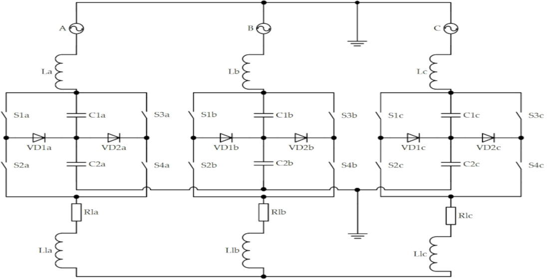
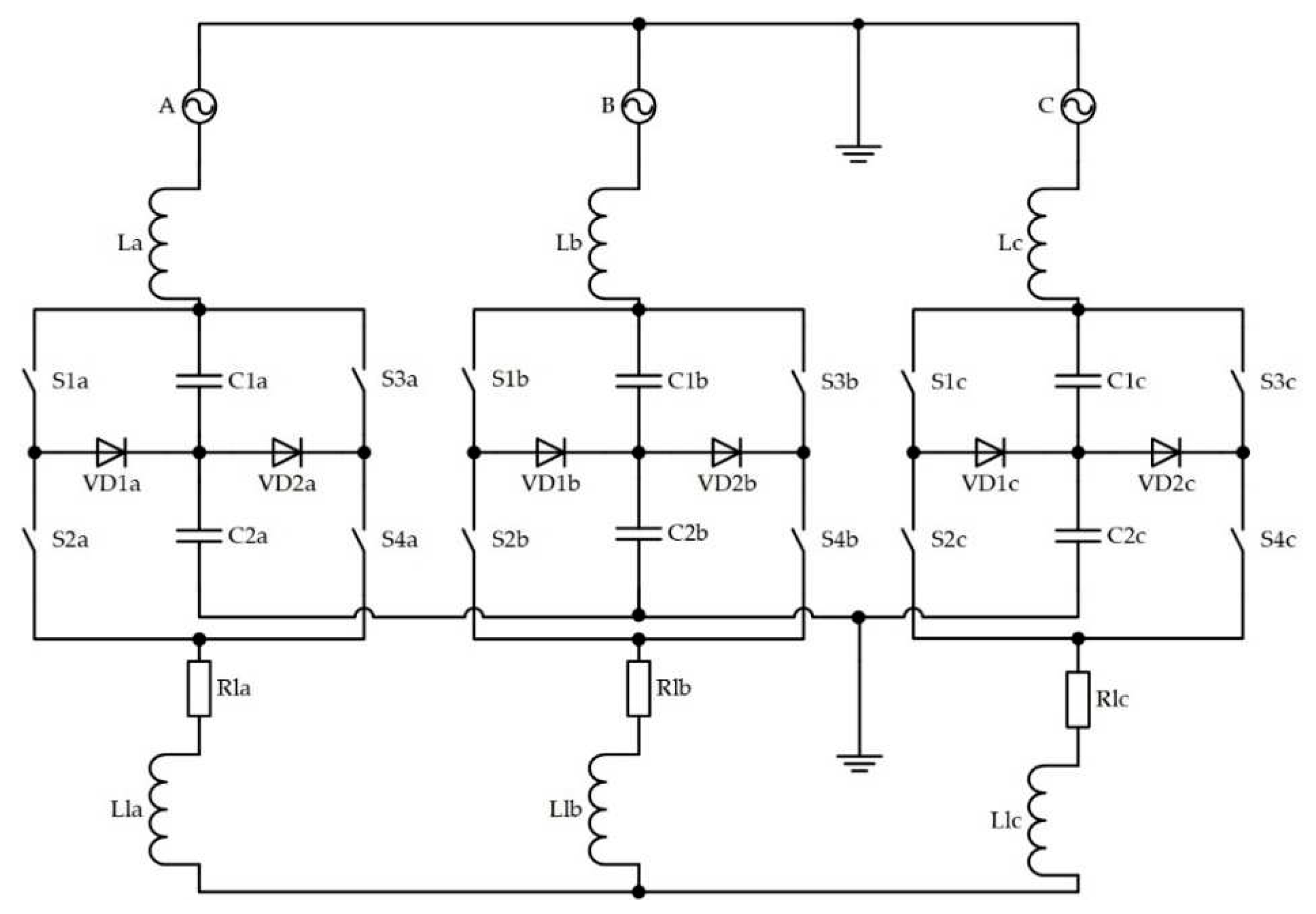
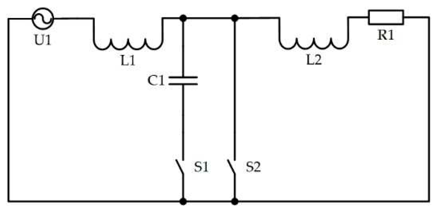
Figure 1 shows a diagram of a two-zone AC voltage regulator. By analogy, converters with a large number of control zones are also being built.
In the case of a two-zone AC voltage regulator, a capacitor divider provides half voltage on the zone relative to the input of the regulator, which gives two regulation zones of the regulator output voltage. AC switches with additional locking diodes are connected in sequential chains, this allows you to get half the value of the mains voltage on all AC keys here, which reduces the cost of AC keys, whether thyristors or transistors.
When using such a converter, the quality of the starting current of the motor improves and the additional consumption of reactive power of the network decreases. The proposed regulator provides a technical result – it has reduced values of reverse voltages on the keys i.e., higher reliability of operation [
20,
21].
In the converter, it is possible to regulate the output voltage by using the method of vertical or pulse-width regulation (depending on the type of key) of the output voltage while maintaining in-phase with the voltage of the supply network.
The application scope of such a system can be the system of municipal heat and water supply, as well as mining and metallurgical electrical equipment.
The next step in the development of this type of regulators was to reduce the number of keys. In particular, the version without diodes. The proposed simplified AC voltage regulator has a reduced number of semiconductor devices. This circumstance reduces the cost of the AC voltage regulator, and can also increase the reliability of operation and increase efficiency.
Figure 2 shows the evolution of a multi-zone AC voltage regulator into a simplified circuit.
A multi-zone AC voltage regulator with increased reliability was also proposed. Increasing the reliability of the AC voltage regulator is realized due to the possibility of switching the divider capacitors within the regulation of one voltage level. This made it possible to balance the voltage on the capacitors of the regulator and thereby reserve the used capacitors. The AC voltage regulator contains n capacitors connected in series, a group of controlled bidirectional switches and a load. A group of managed bidirectional switches consists of 2n+1 managed bidirectional switches and is divided into two subgroups. The AC voltage regulator uses thyristors, transistors or triacs as controlled bidirectional switches. The evolution of a simplified scheme of a multi-zone controller into a controller with increased reliability is shown in
Figure 3.
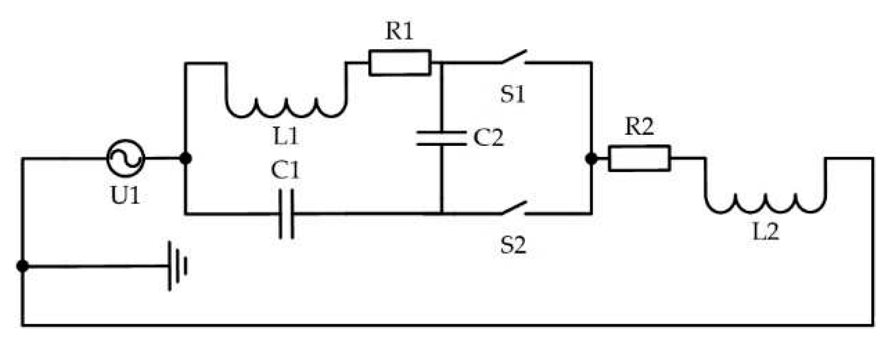
Another class of AC voltage regulators with full number of switches are buck-boost regulators, such regulators can be used primarily as AC voltage stabilizers (
Figure 4).
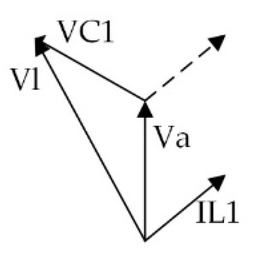
The principle of operation of the regulator: high-frequency pulses, alternately turn on the keys S1 and S2, closing and breaking circuits containing either reactor L1 or capacitor C1. By switching between the vectors of the first harmonics of the voltages U1 and V1L, it is possible to obtain the necessary voltage on the load Vl. The resulting vector Vl is determined by the geometric sum of the vectors qV1C and (1-q)V1L and depends on the relative time q of their switching on. Due to the capacitor C2, during the switching off of the branch with the reactor, the accumulated energy is redirected to the capacitor branch.
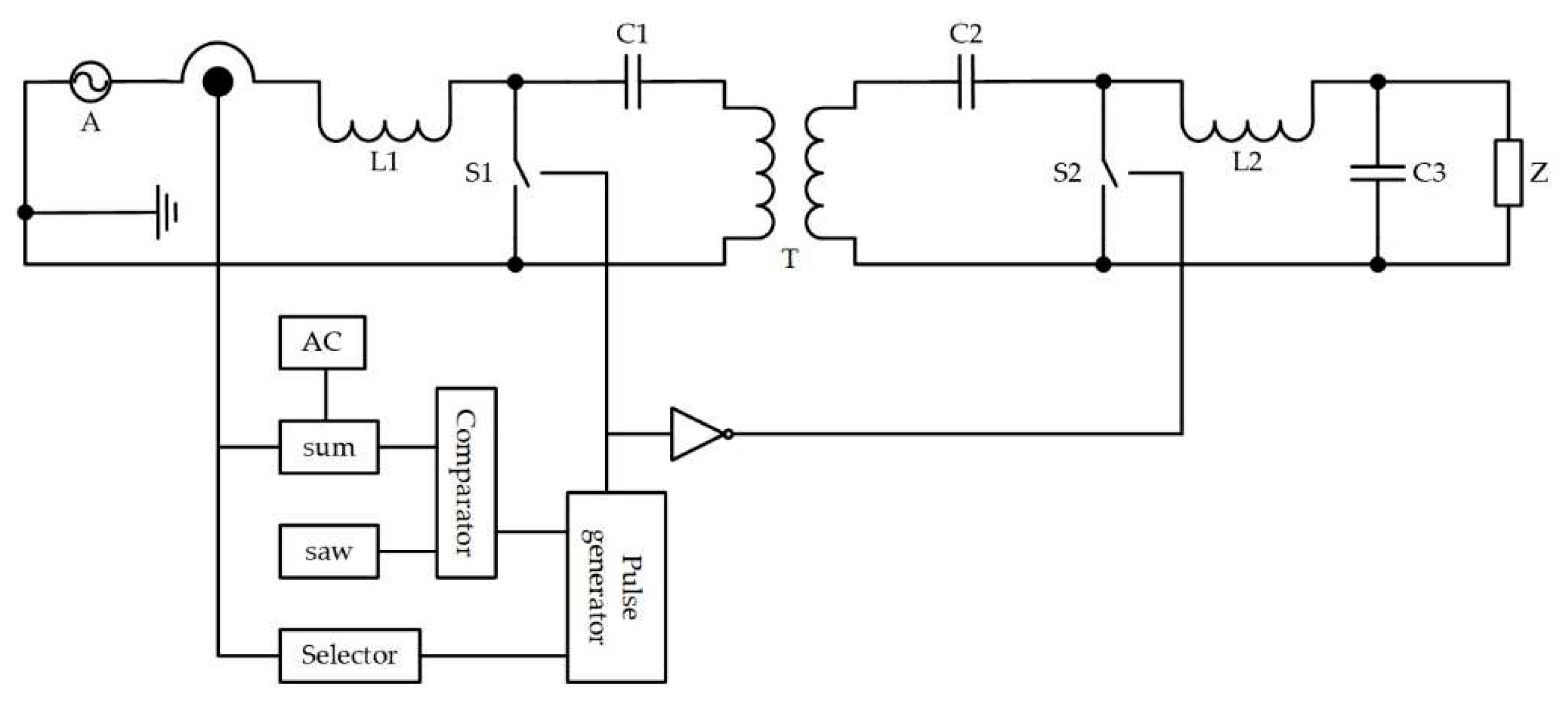
A transformer AC voltage regulator is also proposed, which can be used to obtain a regulated and stabilized three-phase AC voltage with high quality input and output currents,
Figure 5. One phase of the voltage regulator must contain at least a transformer, two AC switches, a storage capacitor of the LC circuit and a load. AC switches are controlled by removing the signal from the current sensor, which is fed to the adder unit, where it is subtracted from the task signal, then compared with the reference signal in the comparison unit, after which the signal is fed to the AC switch control pulse generator.
Three basic structures of AC voltage regulators were presented here, which can be modified by reducing the number of switches without loss of efficiency.
3. AC Voltage Regulators with a Reduced Number of Switches
The previously proposed topology of buck-boost regulators can be simplified by switching either the reactor or only the capacitor branch. For the corresponding circuit, damping resistors and a capacitor are additionally installed, which are necessary to the energy transfer stored in the reactor. Or a resistance must be connected in parallel to the switch, which allows damping the L1C1 circuit, thereby improving the quality of the voltage in the load.
Based on the analysis of current solutions for the construction of AC voltage regulators, the proposed converters under study should have a small number of semiconductor switches and reactive elements, while providing all the necessary functions inherent in regulators.
By switching the switches of the reactor and the capacitor branch, it is possible to achieve voltage regulation on the load, with the possibility of increasing it to 20%. In this type of regulators, the quality of current and voltage also remains high at small and medium values of these indicators.
The evolution of a single-phase circuit of a buck-boost AC voltage regulator into a simplified circuit of a regulator without an AC switch in the capacitor branch is shown in
Figure 6.
The damping resistor R2 and the damping capacitor C2 are necessary so that during the switching off of the branch with the reactor, the energy stored here is redirected to the damping branch.
The three-phase version of such a regulator consists of three parallel-connected AC voltage regulators with an appropriate load, which can be a motor. The proposed simplified buck-boost AC voltage regulator is free from the limitations of typical soft-start devices [
22]: reduced energy indicators during start-up associated with non-sinusoidal forms of output voltages and output/input currents. Also, in this type of regulators, there is no current phase shift relative to the voltage, which in classical circuits increases as the output voltage is regulated down. And finally, there is no limitation of the voltage conversion coefficient in the buck-boost AC voltage regulator.
The next step in the development of AC voltage regulators with a reduced number of switches was the cascade circuits for switching on buck-boost AC voltage regulators with a switched reactor. The evolution of a simplified scheme of buck-boost AC voltage regulators is shown in
Figure 7.
This type of regulators allows you to get an increased output voltage due to a set of connected cells. This method resembles the structure of a multi-zone controller. Next, let's consider another way to optimize the structures of AC voltage regulators with a reduced number of keys.
4. AC Voltage Regulators with One Complementary Pair of Three-Phase AC Switches
The buck-boost AC voltage regulator can be simplified to a circuit with one complementary pair of three-phase AC switches. This is a simple circuit of a buck-boost AC voltage regulator,
Figure 8.
Based on the analysis of the structures of AC voltage regulators [
23], it should be noted that converters should have a small number of semiconductor switches and reactive elements, while providing all the necessary functions inherent in regulators.
Such an AC voltage regulator can be used to obtain a regulated and stabilized three-phase AC voltage with high quality output current. In this solution, the weight and size indicators are improved by reducing the number of transistor switches, in previous schemes, AC switches used a counter-serial connection of switches. The role of AC switches here is performed by a series-connected three-phase diode bridge and a transistor.
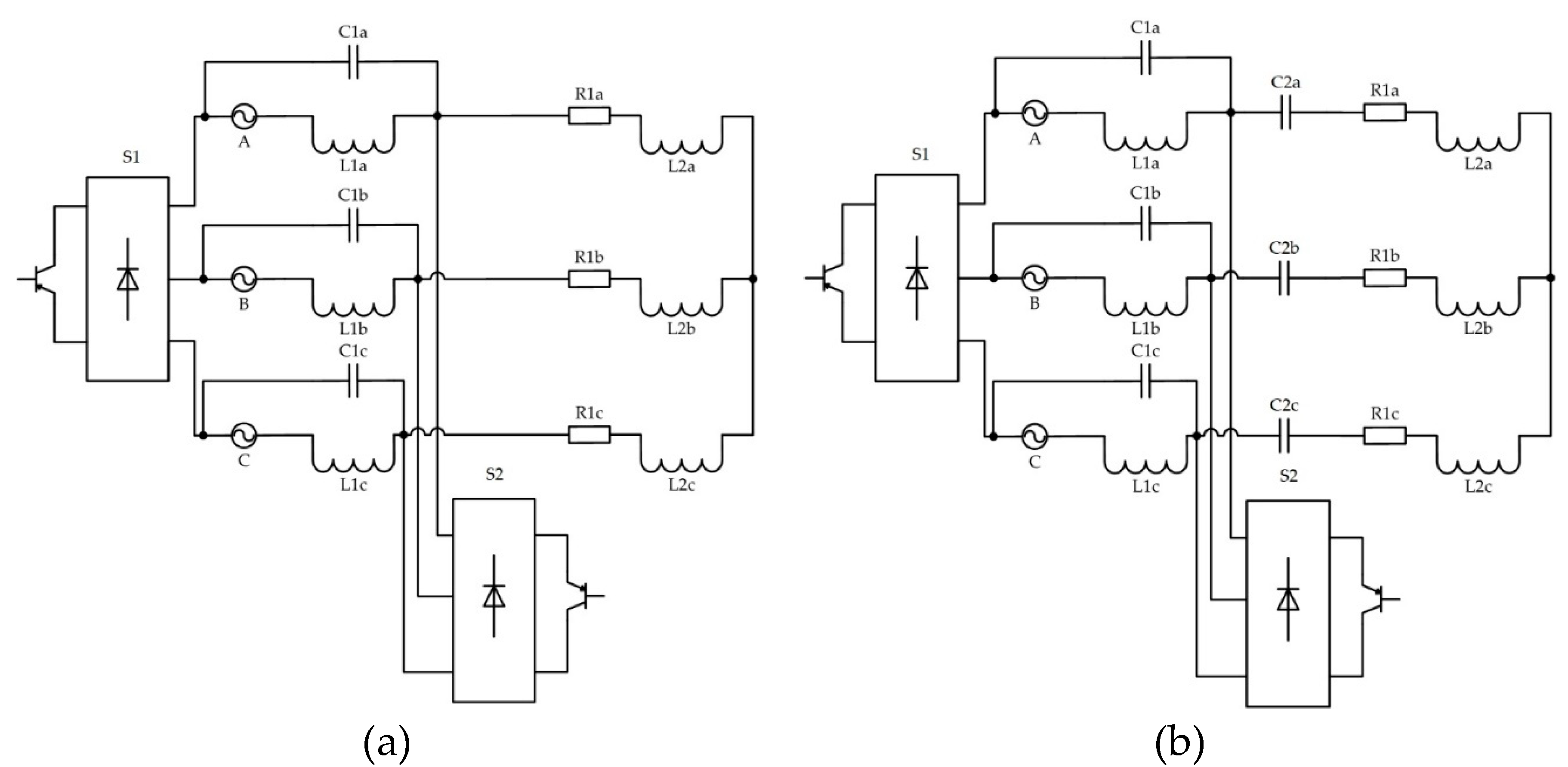
Another type of buck-boost regulators has found application in autonomous systems where there is access to the grid zero, this is an AC voltage regulator with a switched quasi-impedance of the power supply, (
Figure 9).
The operation principle of the regulator (
Figure 9) is as follows: high-frequency rectangular pulses supplied to the key S
1 turns it on, thereby switching the quasi-impedance of the power supply with a high frequency. An external capacitive (capacitor) C
1 impedance is added to the inductive L
1 impedance of the power supply. It is known that the phase of the voltage on the capacitance V
C (
Figure 10) in a serial circuit is opposite to the phase of the voltage on the inductance V
L, i.e. the voltage on the capacitor V
C is added to the voltage of the power supply V
a. Depending on the duration of switching on the key S
1, it is possible to carry out regulation, as a result of which the voltage on the load V
l changes.
The proposed AC voltage regulators with a switched quasi-impedance of the power supply can be used as well as the previous structures in the role of three-phase AC voltage stabilizers. A specific application is also possible in the role of transformer-free devices for increasing alternating voltage, as well as a soft-start device for asynchronous motors [
24,
25]. A feature of this structure is its use in autonomous power supply systems where there is access to the zero network.
Another structure of voltage AC regulator with a low number of switches, the prototype of which was the Ćuk converter, can also be attributed to this class of regulators, with one complementary AC switch for three phases. Such a regulator can be used to obtain a regulated and stabilized three-phase AC voltage,
Figure 11.
Another variant of AC voltage regulator with a low number of switches with a transformer is shown in
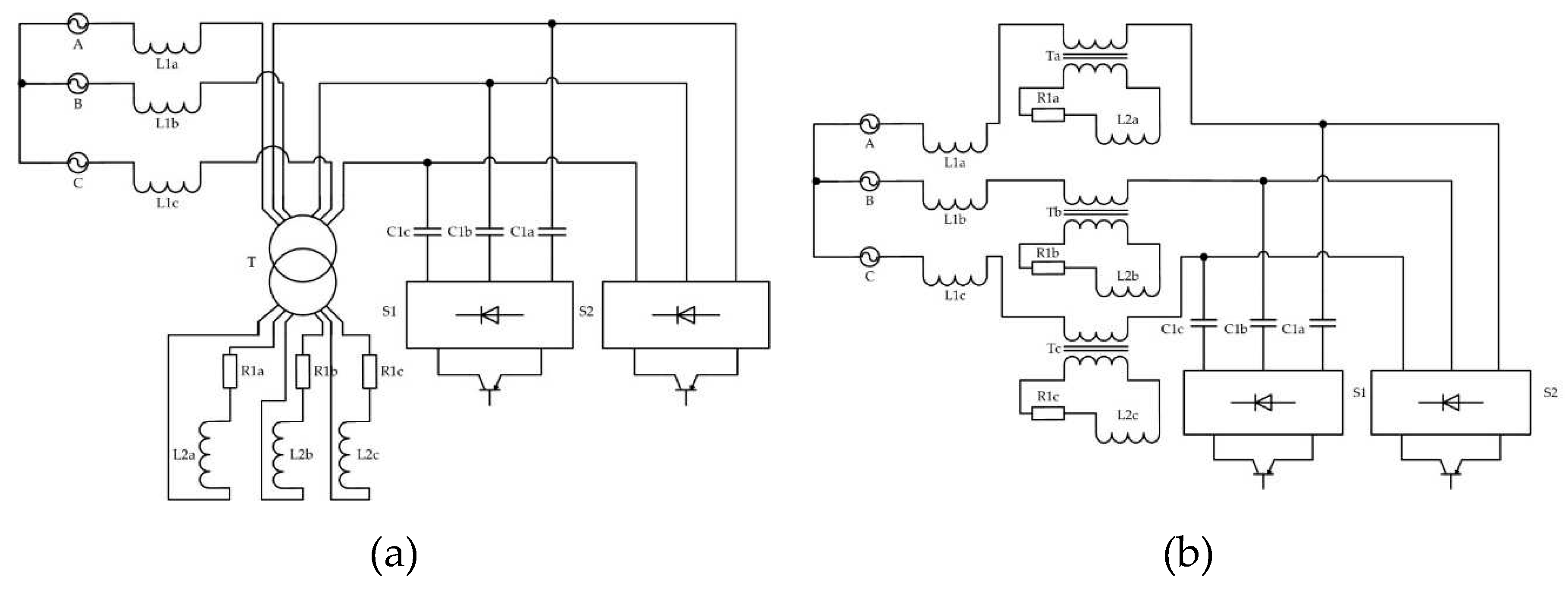
Figure 12. Such an AC voltage regulator can be used to obtain a regulated and stabilized three-phase AC voltage with high quality input and output currents. The main feature of such a scheme is to provide galvanic isolation of the load from the network.
The proposed converter was compared with the known values of the reactive power of capacitors at the level of 100 kvar. The value of the reactive power of the capacitors varied from 5.5 to 63 kVA, which in relative units ranged from 6 to 65% [
26]. These schemes of AC voltage regulator with a low number of switches can also be used as reactive power compensators.
5. Calculation and Modeling of AC Voltage Regulators with a Full Number of Switches
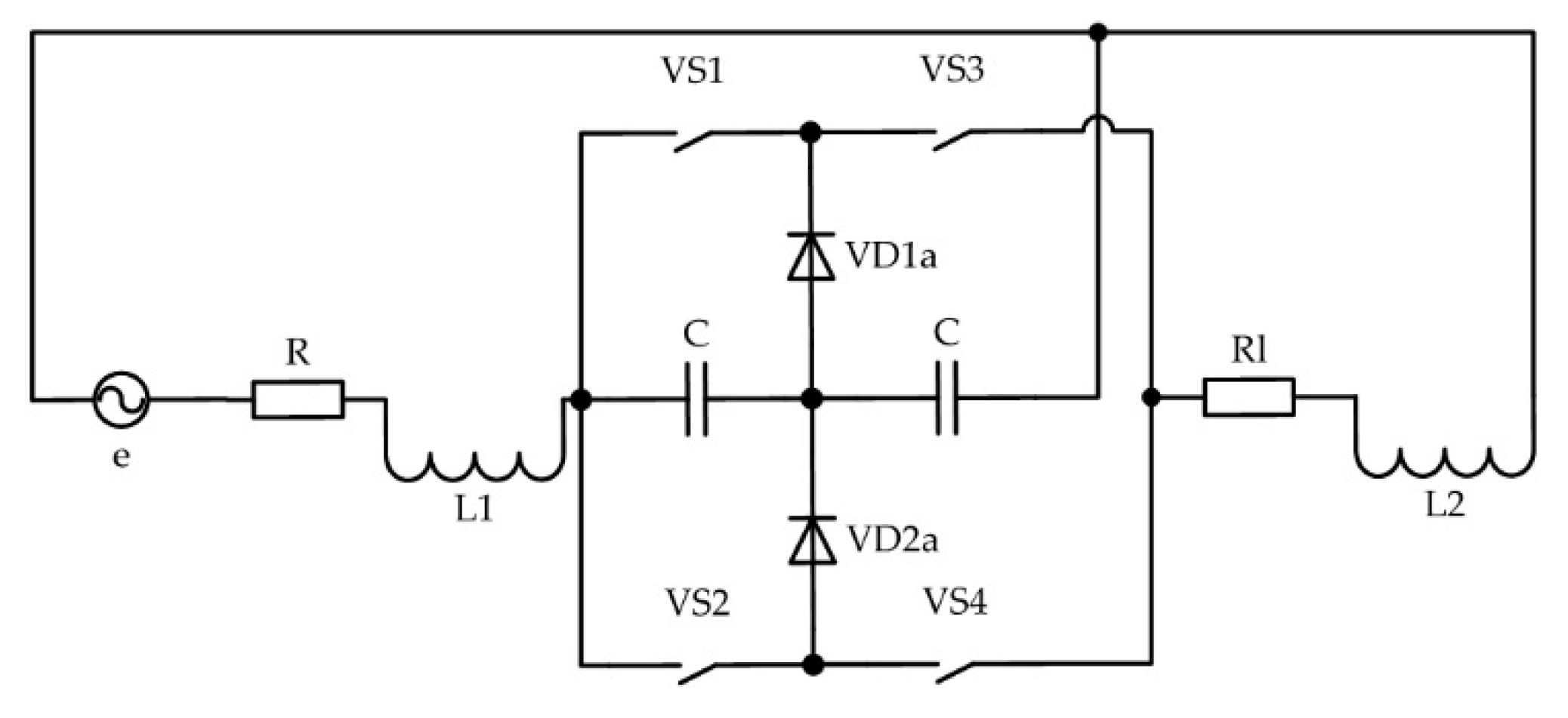
The calculation of currents and voltages for one phase of a two–zone AC voltage regulator,
Figure 13, was performed using a direct calculation method that does not require the use of differential equations - the method of algebraization of differential equations (ADE) [
27].
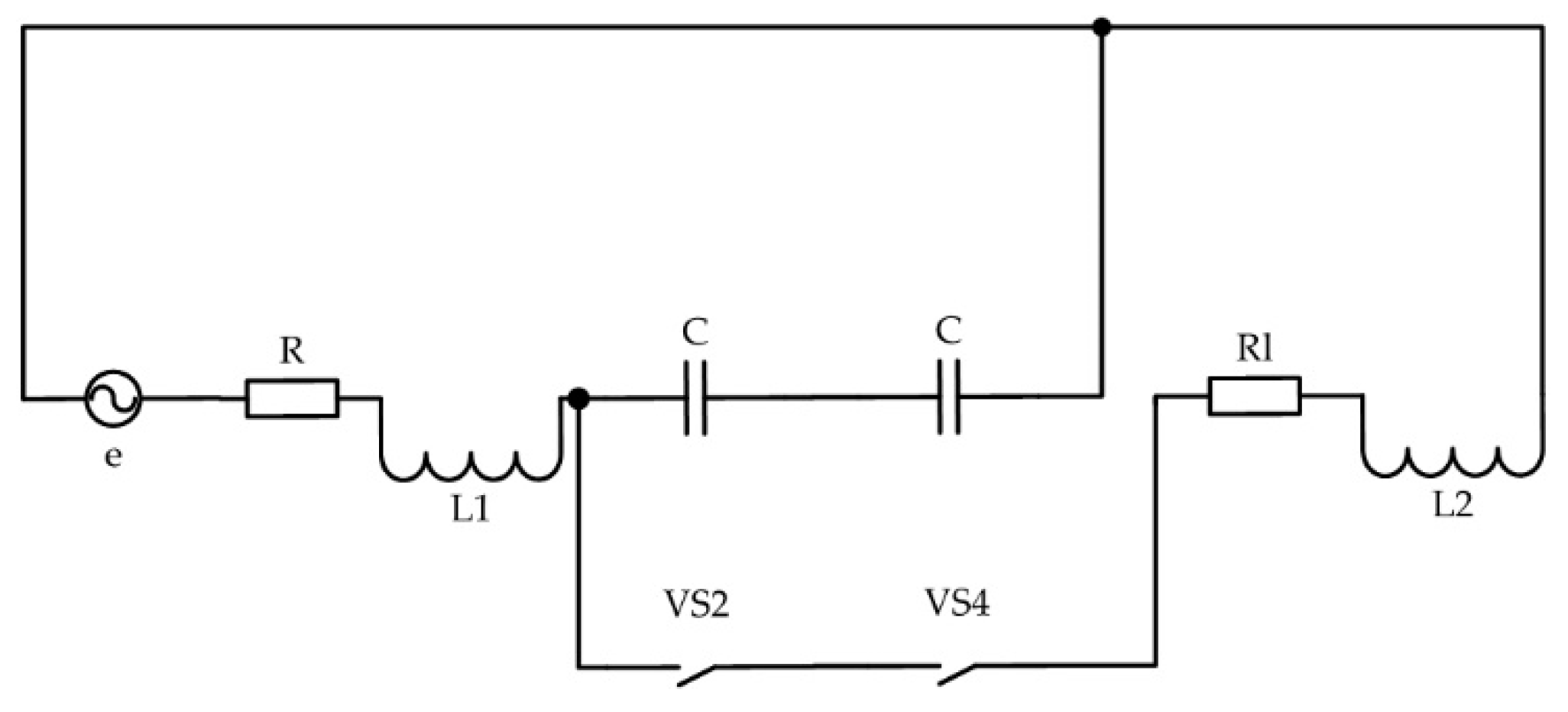
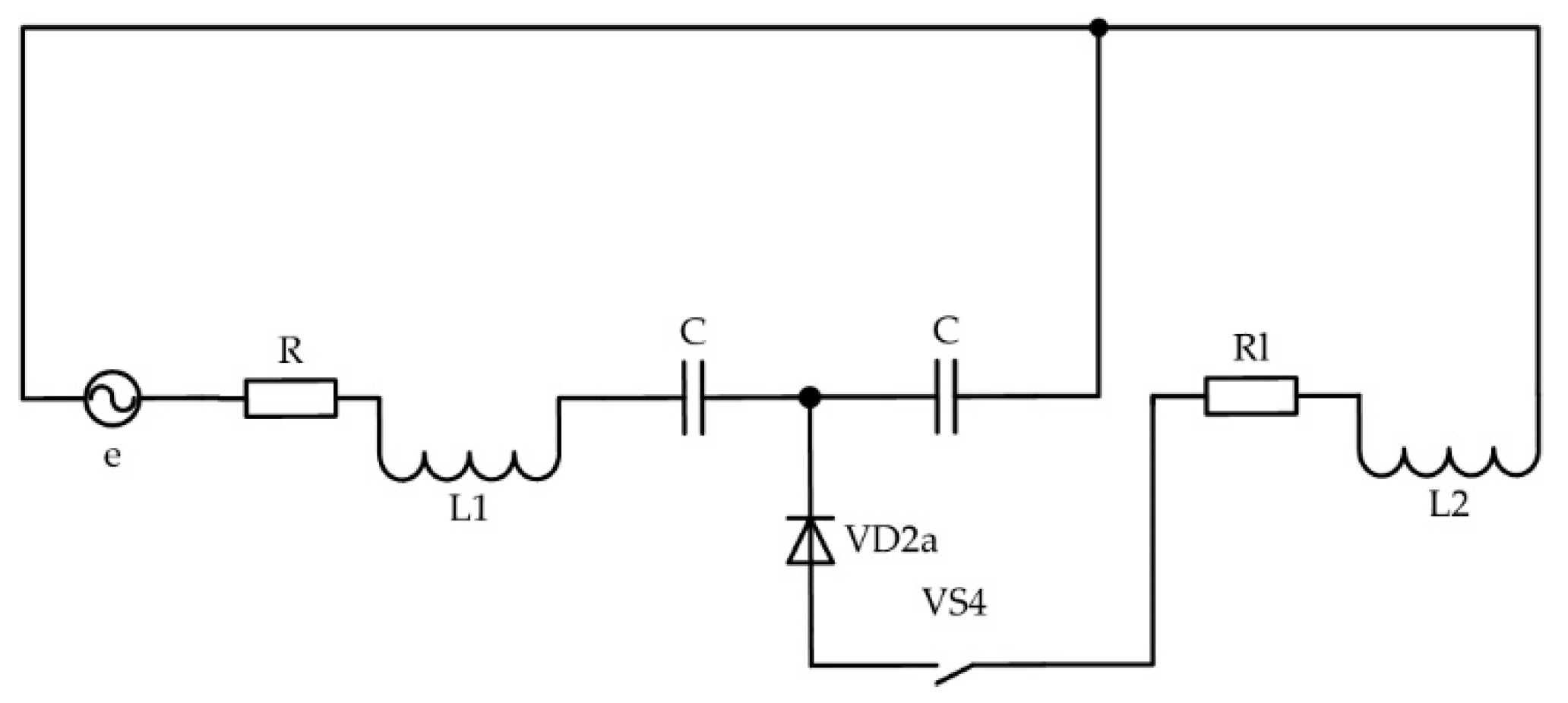
Figure 14 and
Figure 15 show equivalent regulator circuits for the first half-wave of the input signal of the device.
We will find the first harmonic of the load current using the first and second Kirchhoff laws.
Assume:
il=x1, uC1=x2, uC2=x3, i1=x4, e=u1
The general equation for both subintervals of work in matrix form:
where C
1=C
2=C, ψ is the switching function of the transition from the subinterval of operation No. 1 to the subinterval of operation No. 2.
We obtain similar expressions for the second half-wave of the input signal of the controller when two switches of the second branch of the device are operating.
We introduce two matrixes of two halves of periods into one common one, while the switching functions of each half-period will take the form:
for the first half of the period ,
for the second half of the period ,
half-wave switching function of the input signal for the entire system .
Then the resulting equation for the entire period in matrix form will take the form:
A mathematical model of the regulator in the form of a system of first-order differential equations with variable coefficients is obtained. Complex expressions from switching functions in the matrix can be replaced with a new function, the form of which is constructed according to the corresponding expressions for the coefficients of the equations.
Matrix of variables using analytical recording of the first harmonics of the switching functions:
where
Coefficients were introduced:
, , .
In order to apply the ADE according to the first harmonics, it is necessary to decompose all variables into harmonic functions.
The final system of equations in the form of a matrix:
where:
, .
Thus, we will use Kramer's formula and find the determinant of the system:
where:
, , , .
To find the voltages and currents of the system, respectively, Δ1-ΔJ are found, which are obtained from Δ by replacing its J-th column, from where:
etc.
The calculation of the multi-zone AC voltage regulator was also performed using the switching function method.
To simplify the implementation of the mathematical model, losses in switches and reactive elements of the circuit were not taken into account.
At the first stage of the calculation, switching functions determined by the laws of switching of AC switches were calculated. These functions are used to describe the output voltages. Next, a mathematical description of the output phase and linear voltages of the regulator is performed. Then, if necessary, you can describe the currents, define them as instantaneous, average, effective values and their spectral compositions.
The implementation of the mathematical model of a multi-zone AC voltage regulator begins with a description of the input sinusoidal voltages of the supply network:
Next, the control principle of a multi-zone AC voltage regulator is set. The law of change of reference signals in the implementation of these mathematical models adopted a sawtooth shape [
28]:
where
is the index describing the phase number, k is the number of phases of the voltage regulator.
The modulating signals are set by constants proportional to the control angle:
Next, there is a description of the switching functions that determine the switching points of the switches of the multi-zone AC voltage regulator. This happens when comparing reference and modulating signals. The implementation of simulated comparators occurs through the use of the Heaviside function or the "signum" function, the result will be identical:
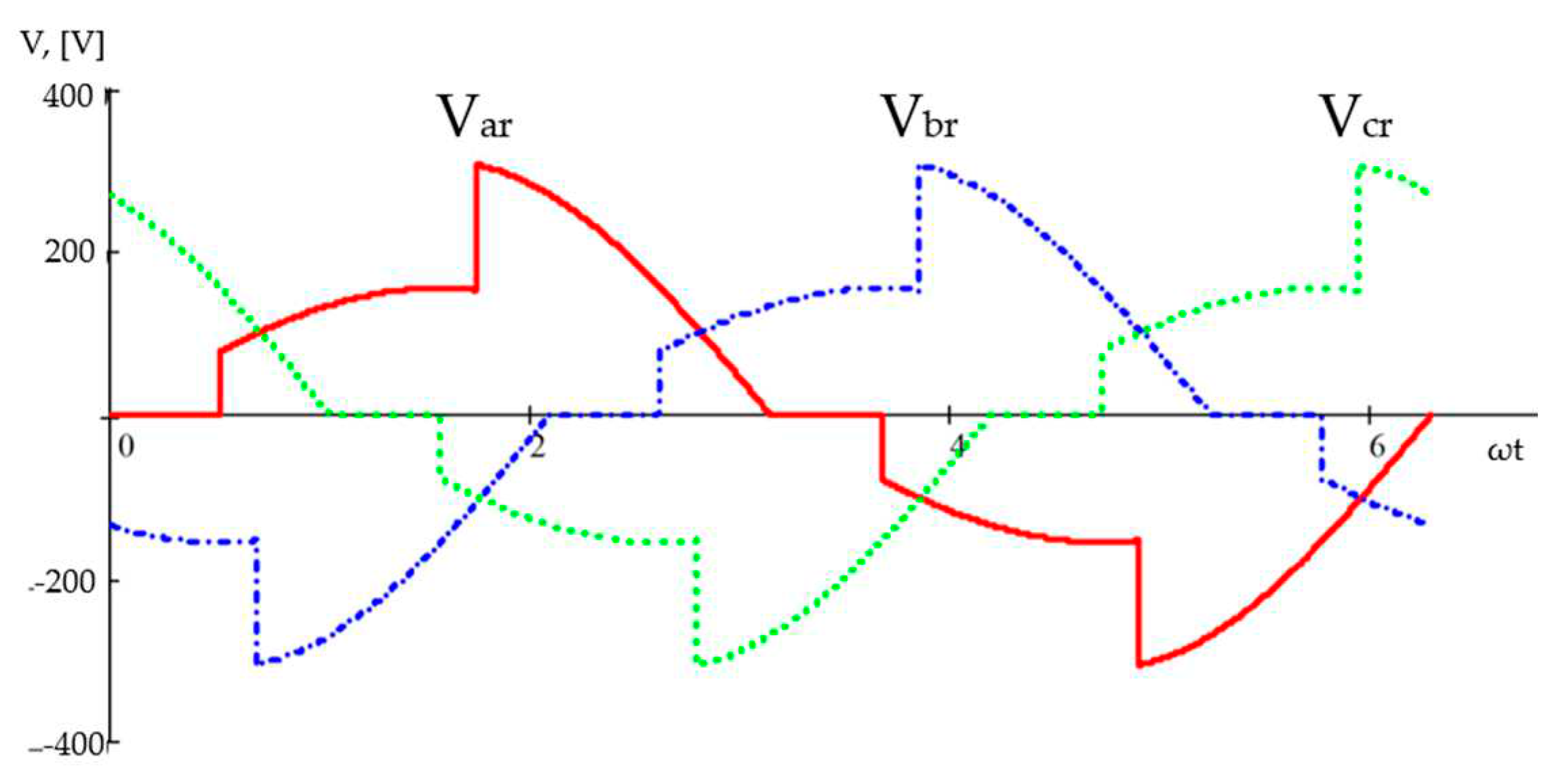
The resulting switching functions determine the duration of operation of the corresponding switches pair. The output voltage, taking into account the switching functions, is determined by the following ratios:
The form of the output voltages obtained from these expressions is shown in
Figure 16.
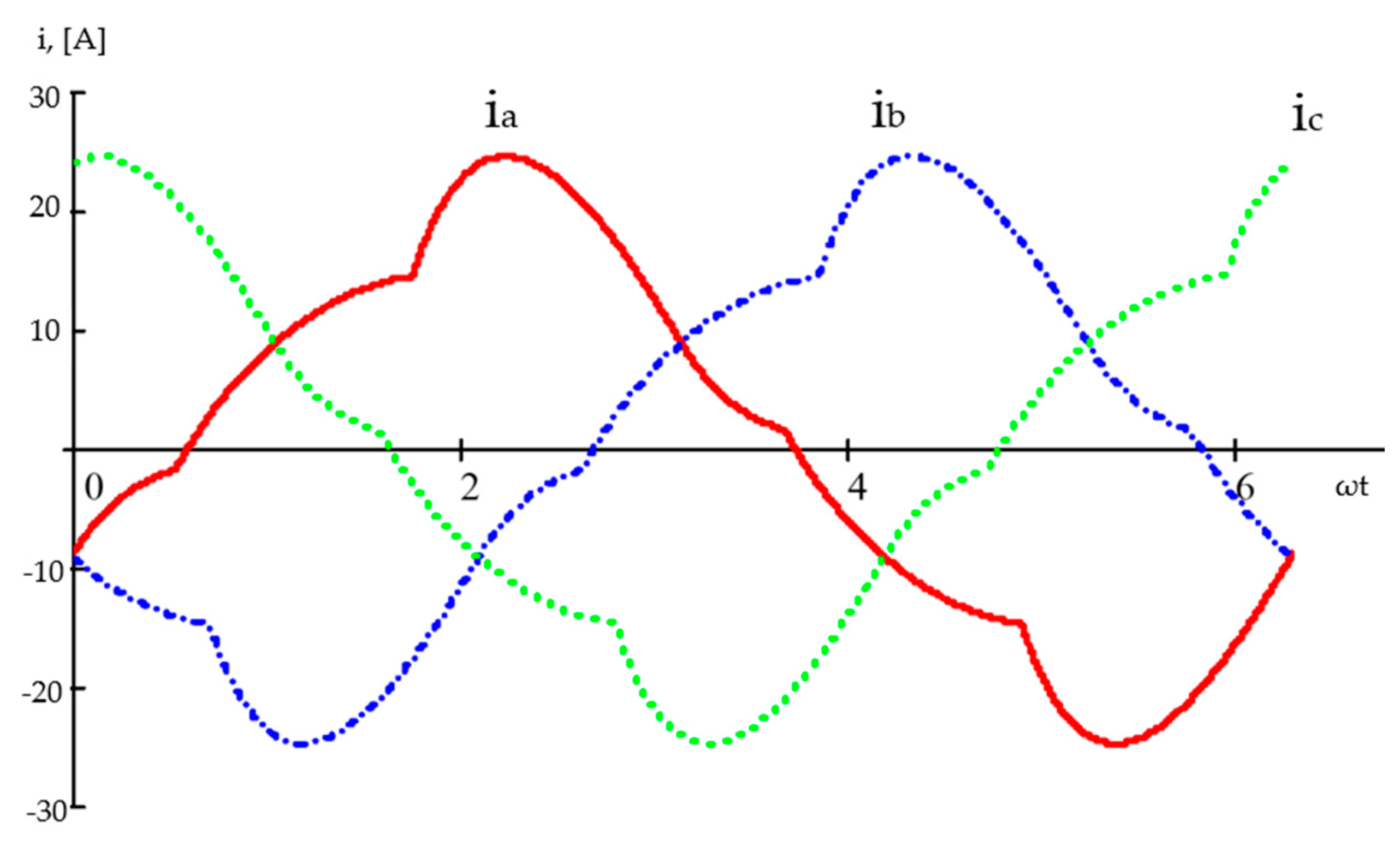
After the description of the output voltages has been obtained, a mathematical description of the load currents of the AC voltage regulator can be performed in the same way. To determine the currents of a multi-zone regulator, a harmonic voltage analysis is initially performed. For this, we apply the calculation of the harmonics of the output voltages through the coefficients of the Fourier series. Fast algorithms of discrete Fourier transform are used to speed up the calculation process and improve accuracy.
Finally, diagrams of the load current of a three-phase AC voltage regulator were obtained,
Figure 17.
It is possible to conduct their harmonic analysis using the same procedure as for voltage having received a mathematical description of the load currents. For example, we apply the fast Fourier transform for phase A current:
It is possible to calculate the harmonic coefficient of the current and the integral harmonic coefficient of the current knowing the vector column of harmonic components of the Fourier series in complex form for the phase current:
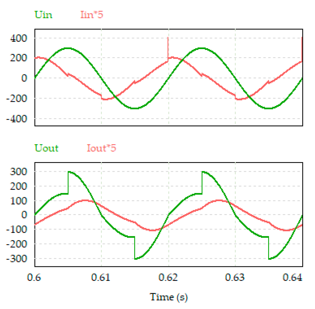
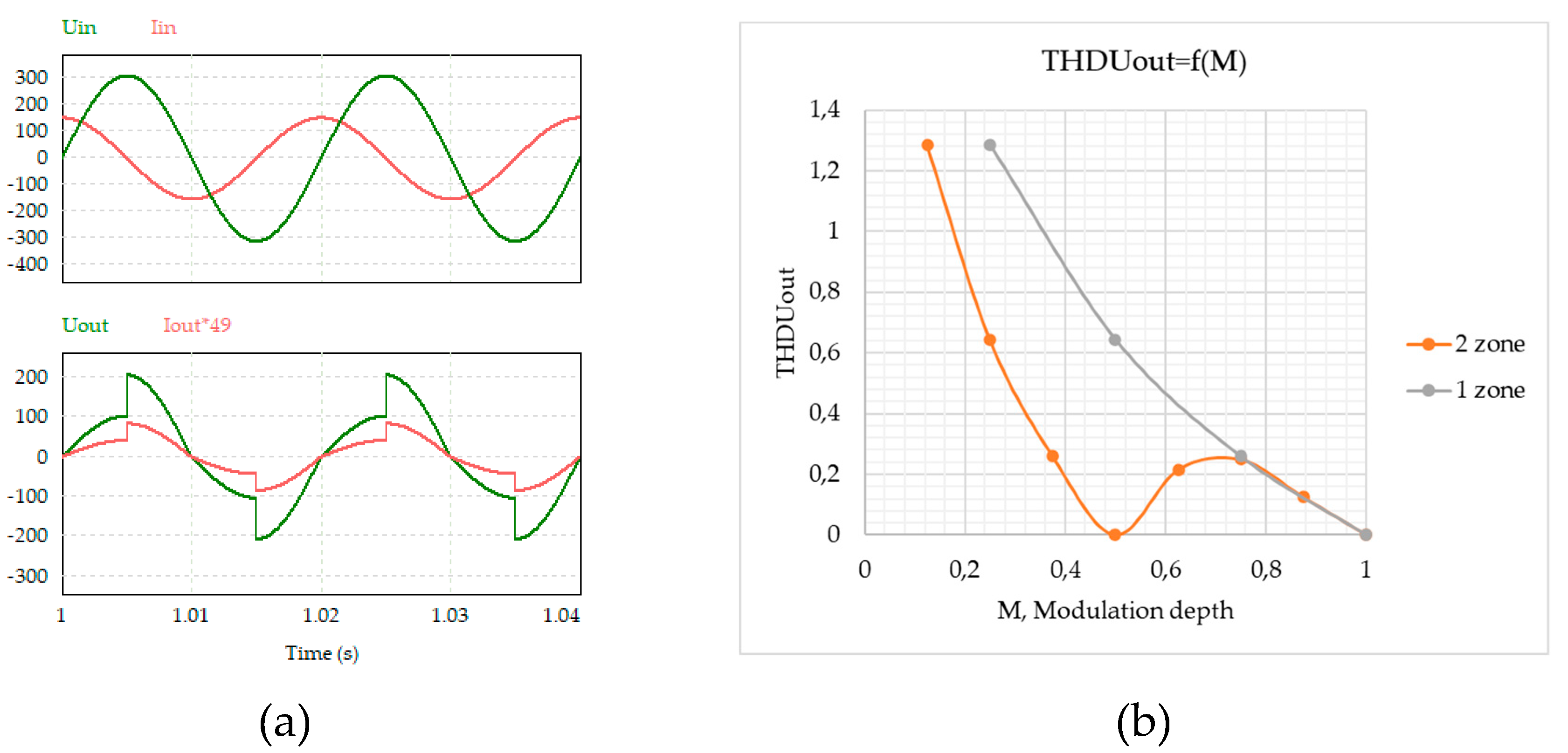
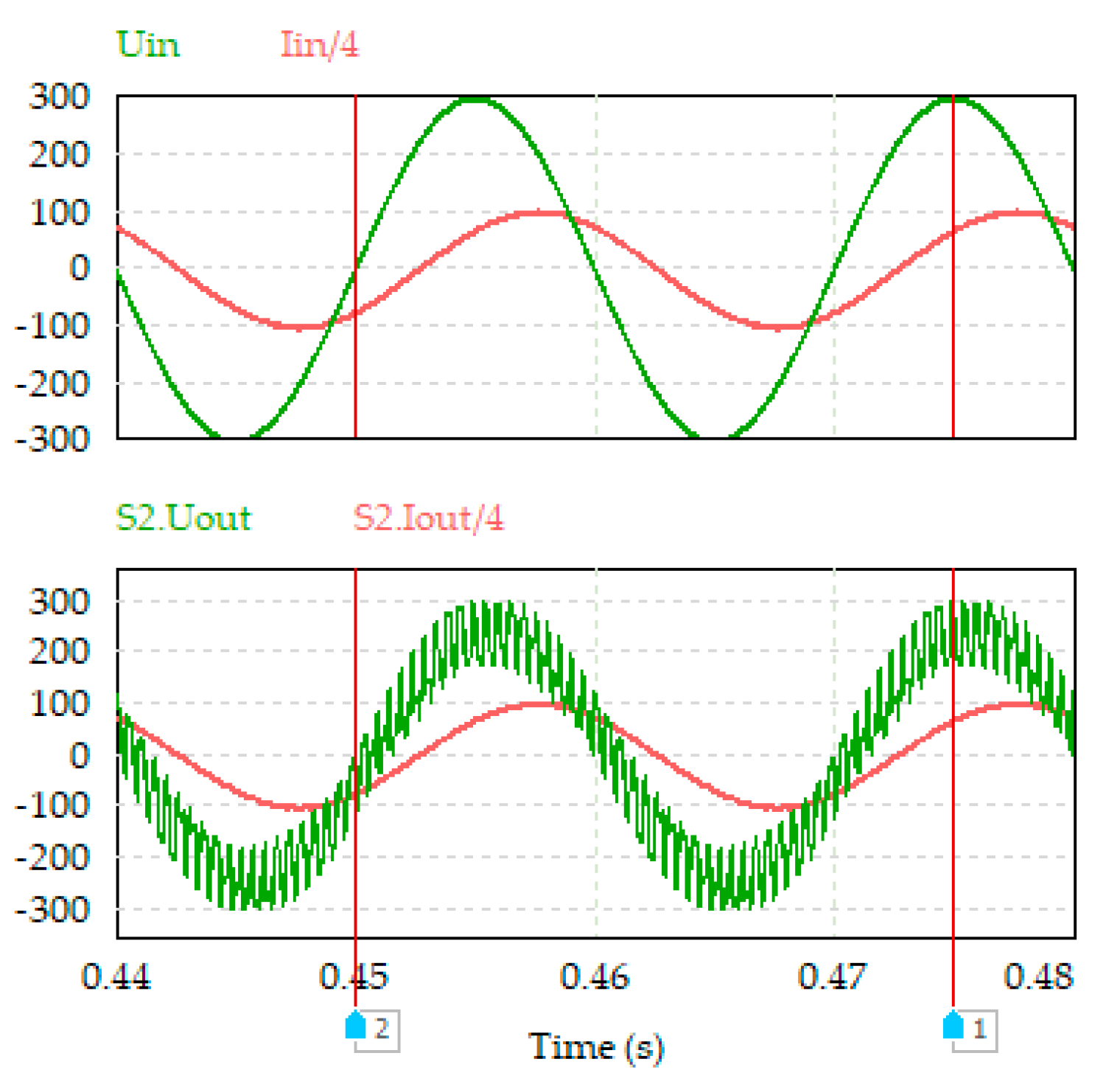
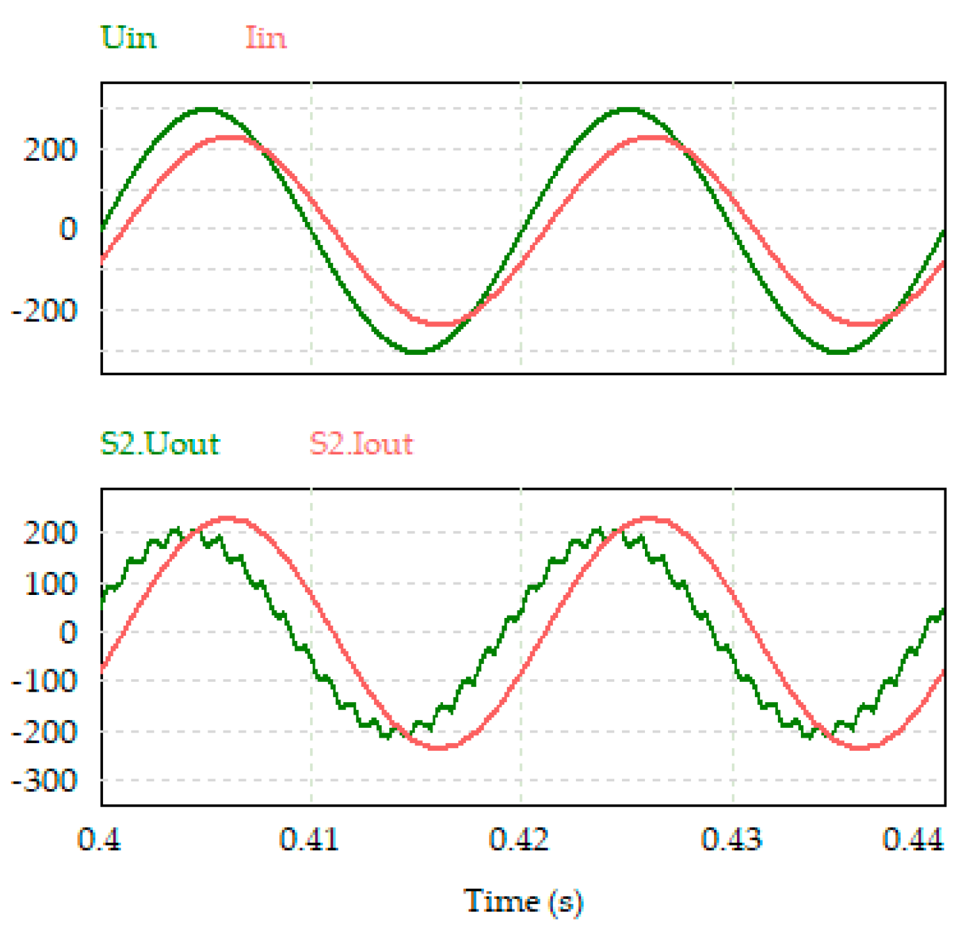
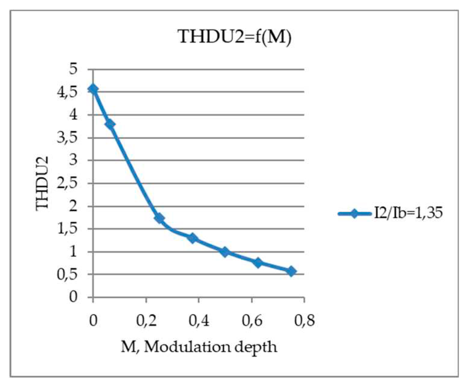
Figure 18 shows the simulation results in the PSIM software. The input and output currents and voltages in the second regulate zone are presented. Next, we will compare these results with the results of the analytical calculation. The proposed mathematical apparatus makes it possible to determine the harmonic coefficients of currents and voltages of the proposed regulators. The harmonic coefficient of the input and output current of the two-zone AC voltage regulator is estimated to be less than 5% [
29,
30,
31].
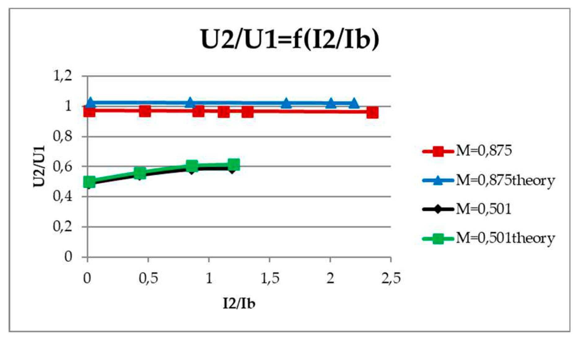
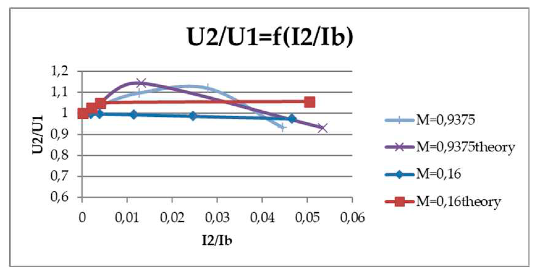
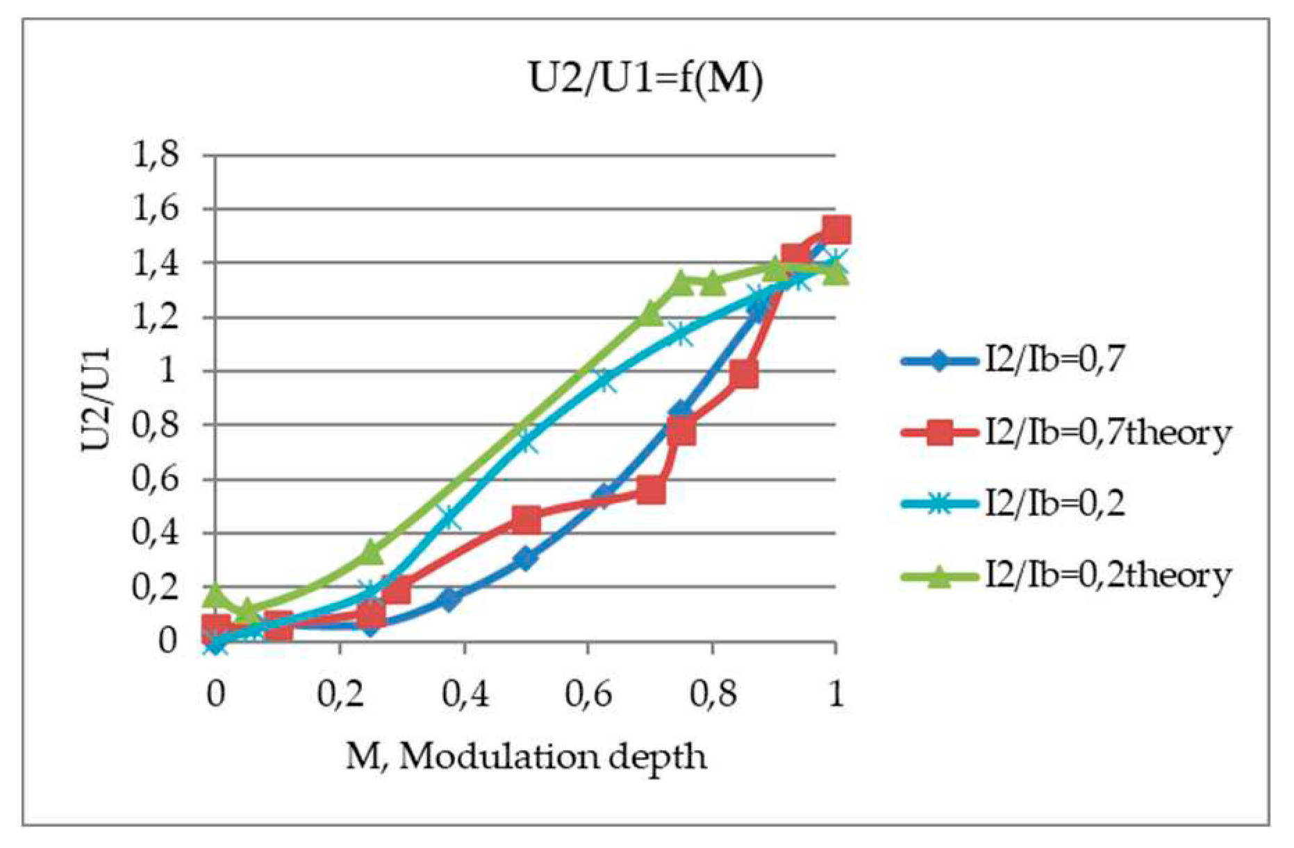
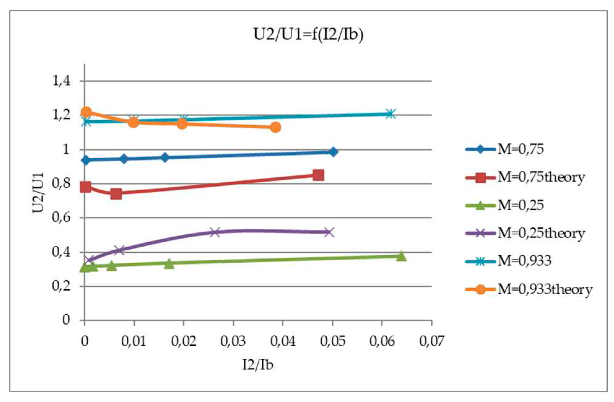
Based on the results of calculations, a family of load characteristics,
Figure 19, of a two-zone AC voltage regulator is constructed together with the results obtained in the PSIM model.
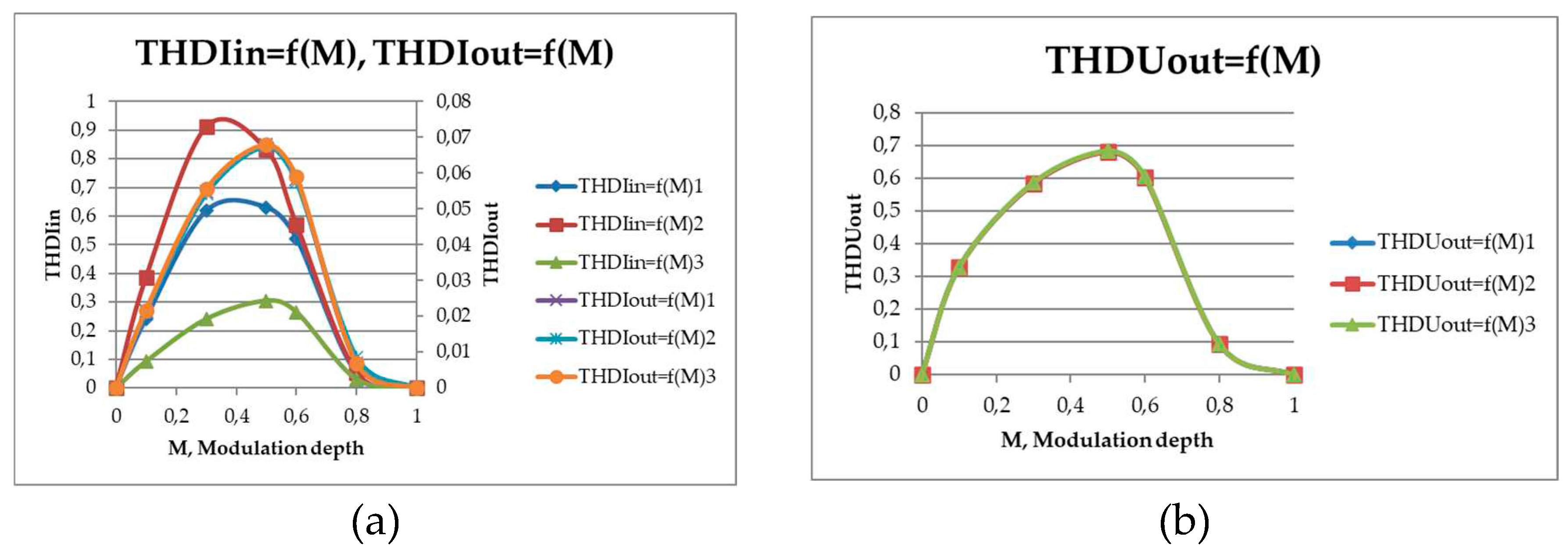
Figure 20 shows the curves of the input and output current and voltage a), as well as the harmonic coefficient of the output voltage b).
Figure 21 shows the waveforms of the output voltage of a multi-zone AC voltage regulator with increased reliability, for a) standard operating mode, for b) with different voltage levels on the capacitors.
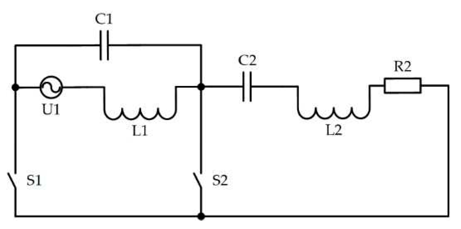
The qualitative characteristics of a single-phase buck-boost AC voltage regulator were also evaluated,
Figure 22. As before, the ADE method was applied here and a mathematical model of the regulator was built.
For cases when the key S
1 or S
2 is switching on, differential equations are constructed:
The first harmonic of the spectrum of the switching function looks like this:
Here f – is the switching frequency, M1=1–M, M – is the modulation depth.
When using the ADE method, all variables of the system of equations (17) are decomposed into harmonic functions, then their first harmonics are split into active (a) and reactive (r) components orthogonal to each other. After averaging over the period of the first harmonic, we obtain a system of algebraic equations for sine and cosine components written into a matrix:
where
by
.
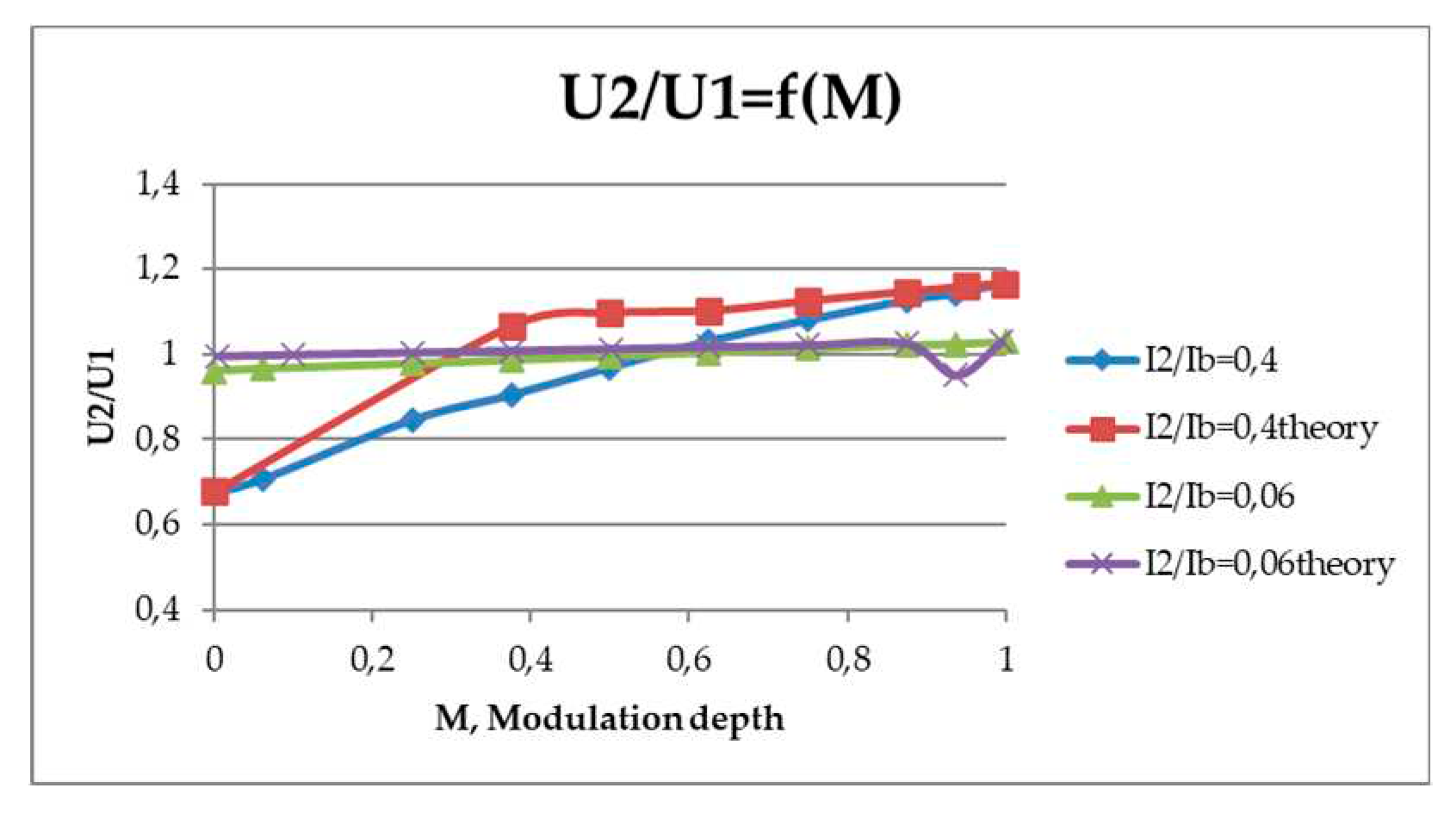
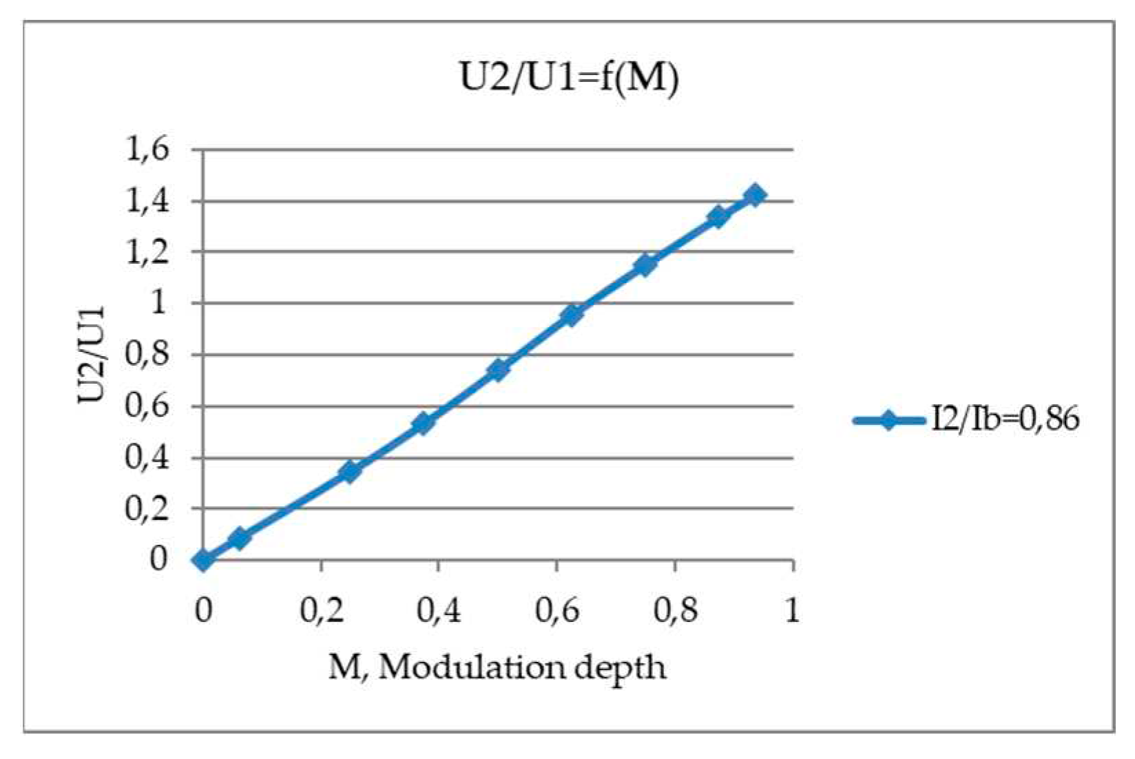
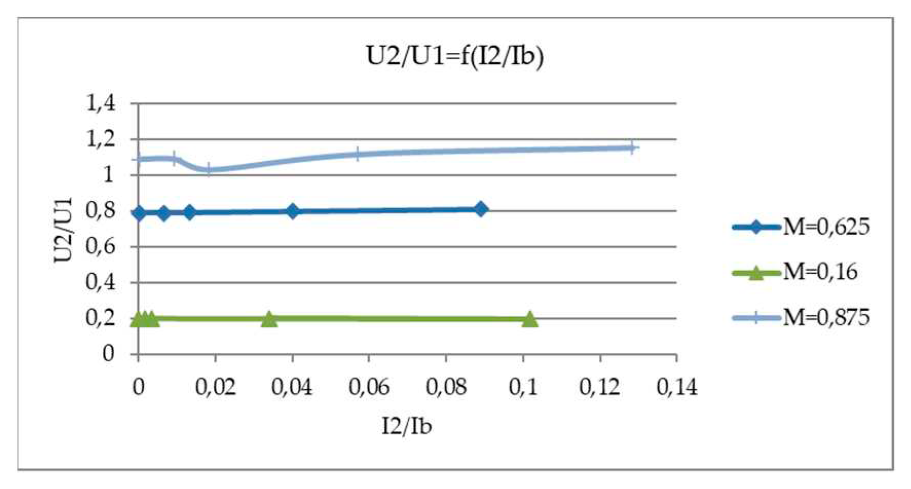
Next, the control characteristic
,
Figure 23, and the load characteristic of the regulator
,
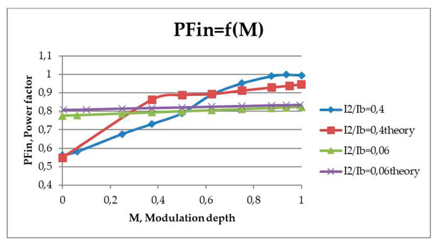
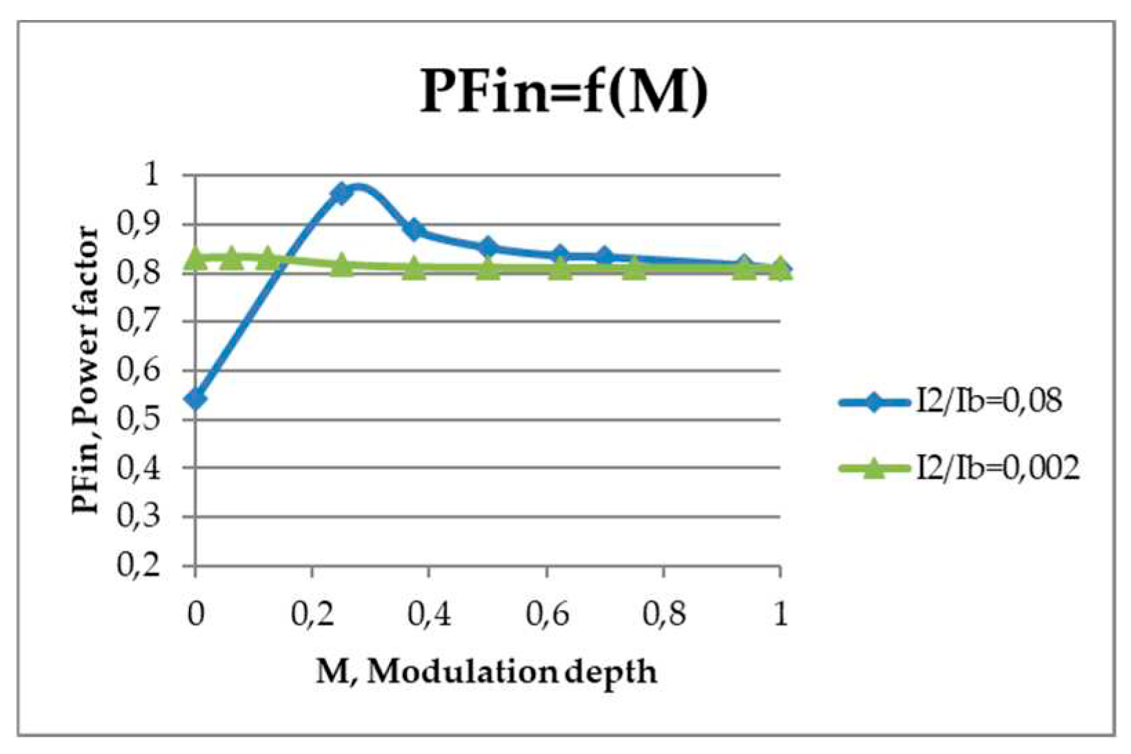
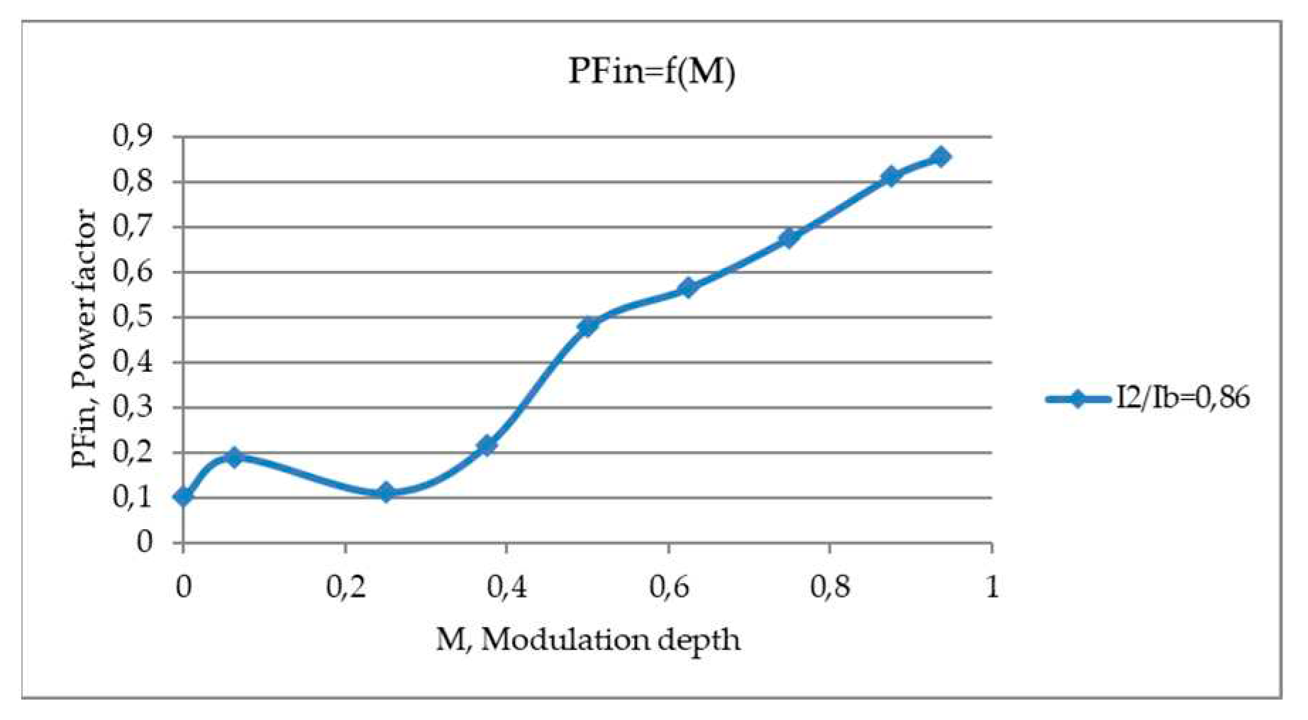
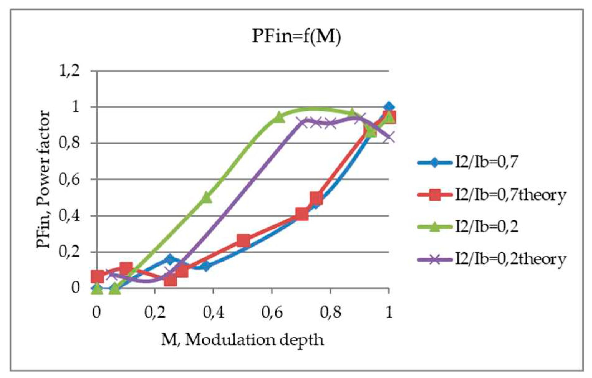
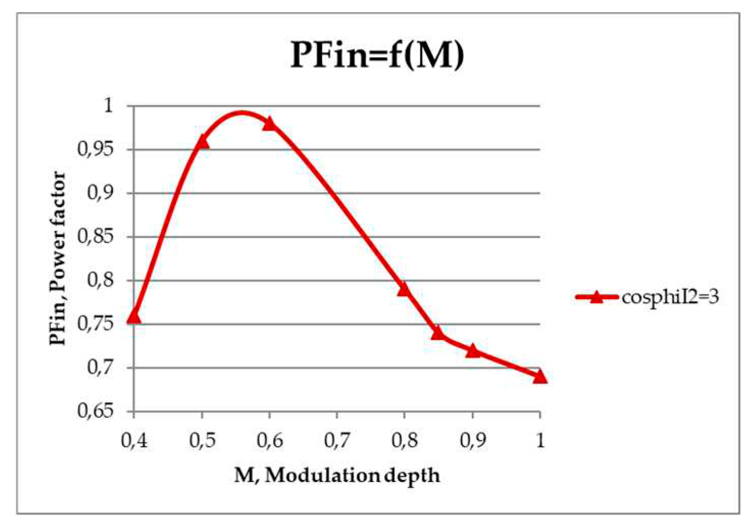
Figure 24 were constructed. The dependence of the input power factor relative to the modulation depth was also determined
,
Figure 25.
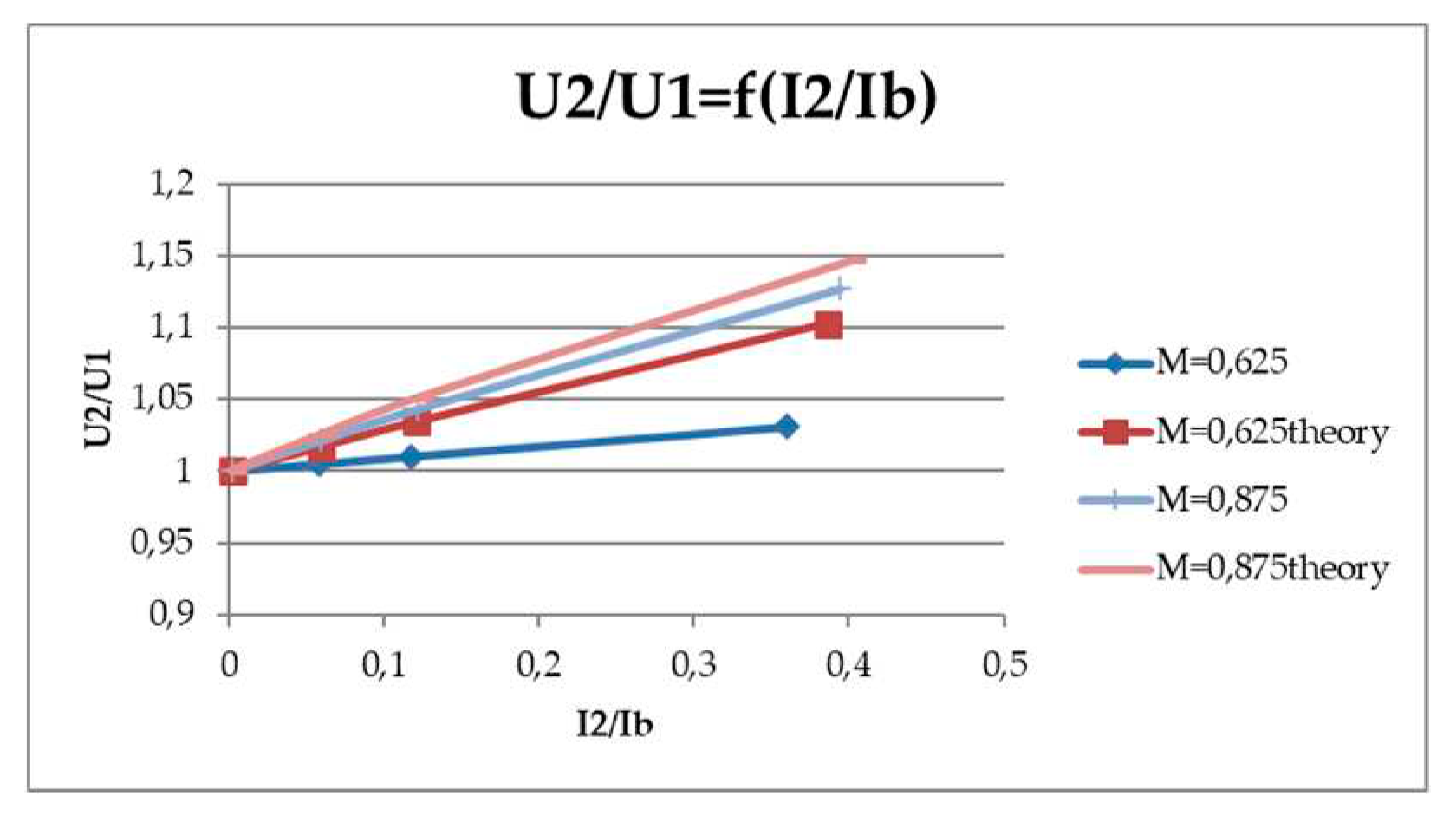
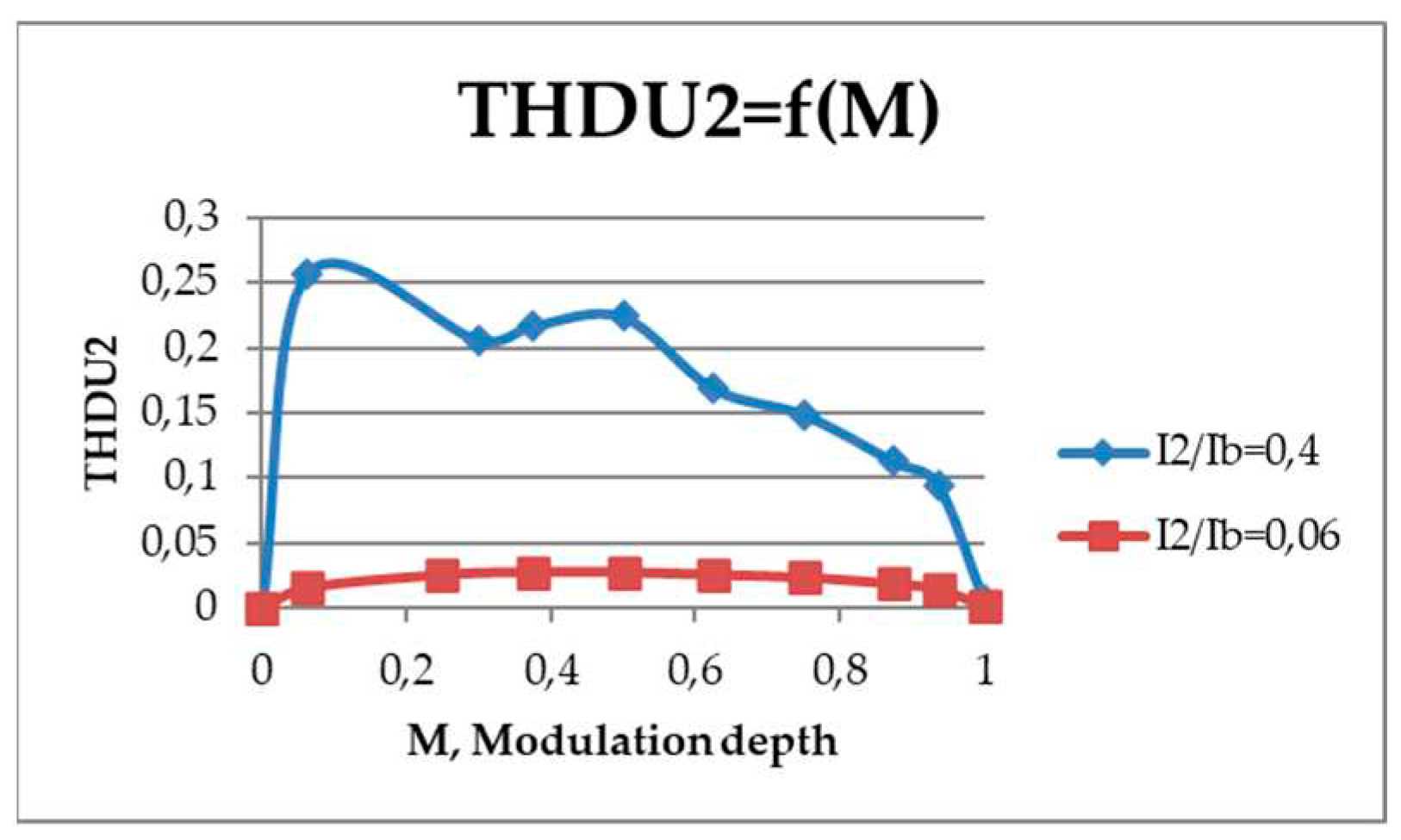
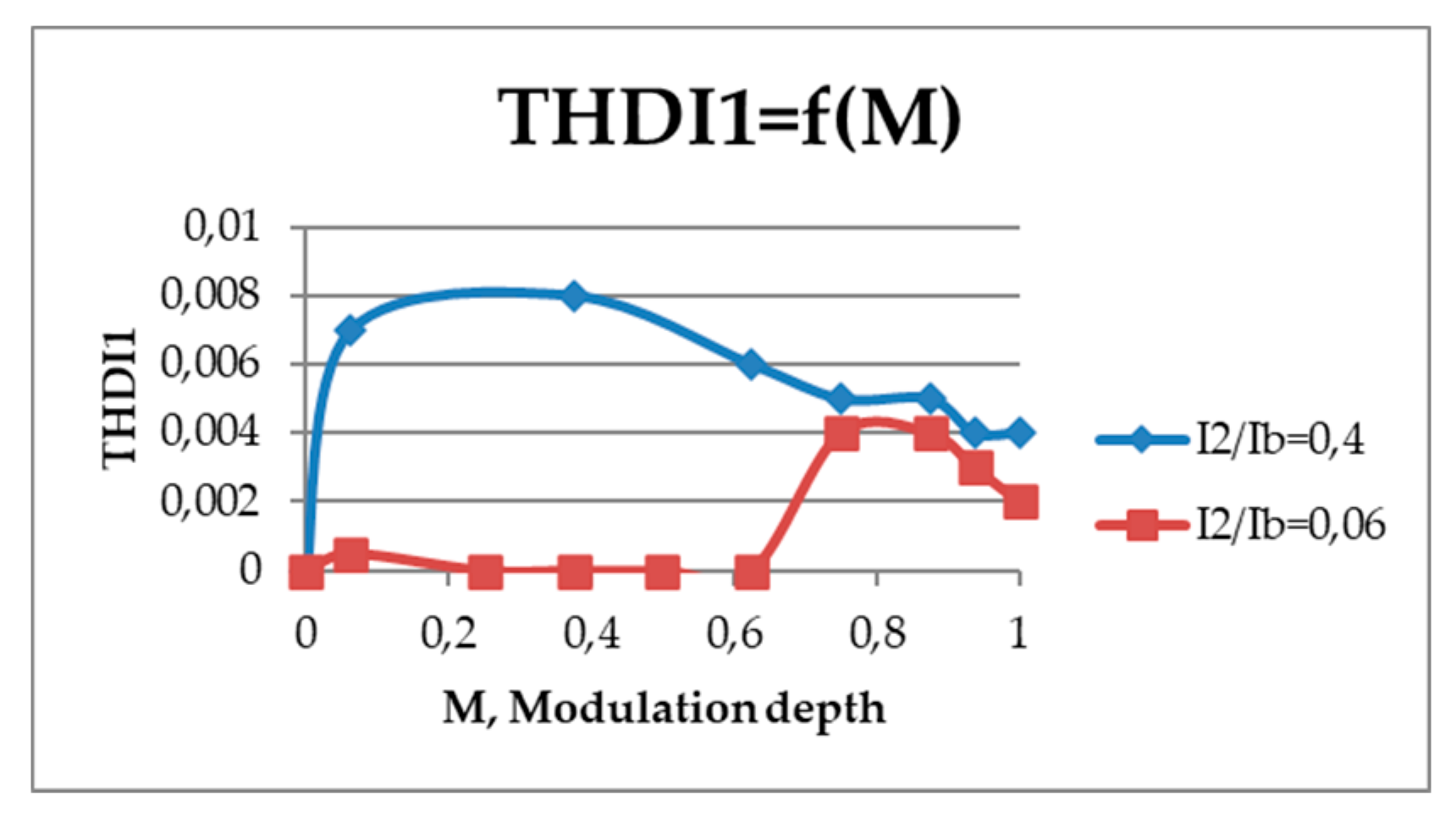
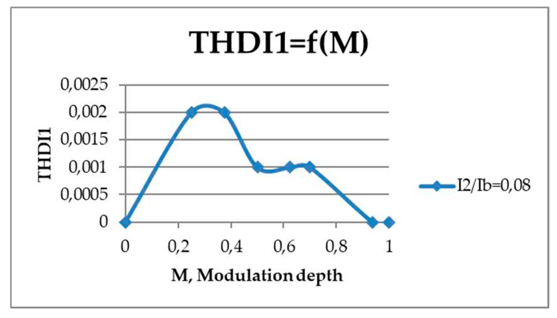
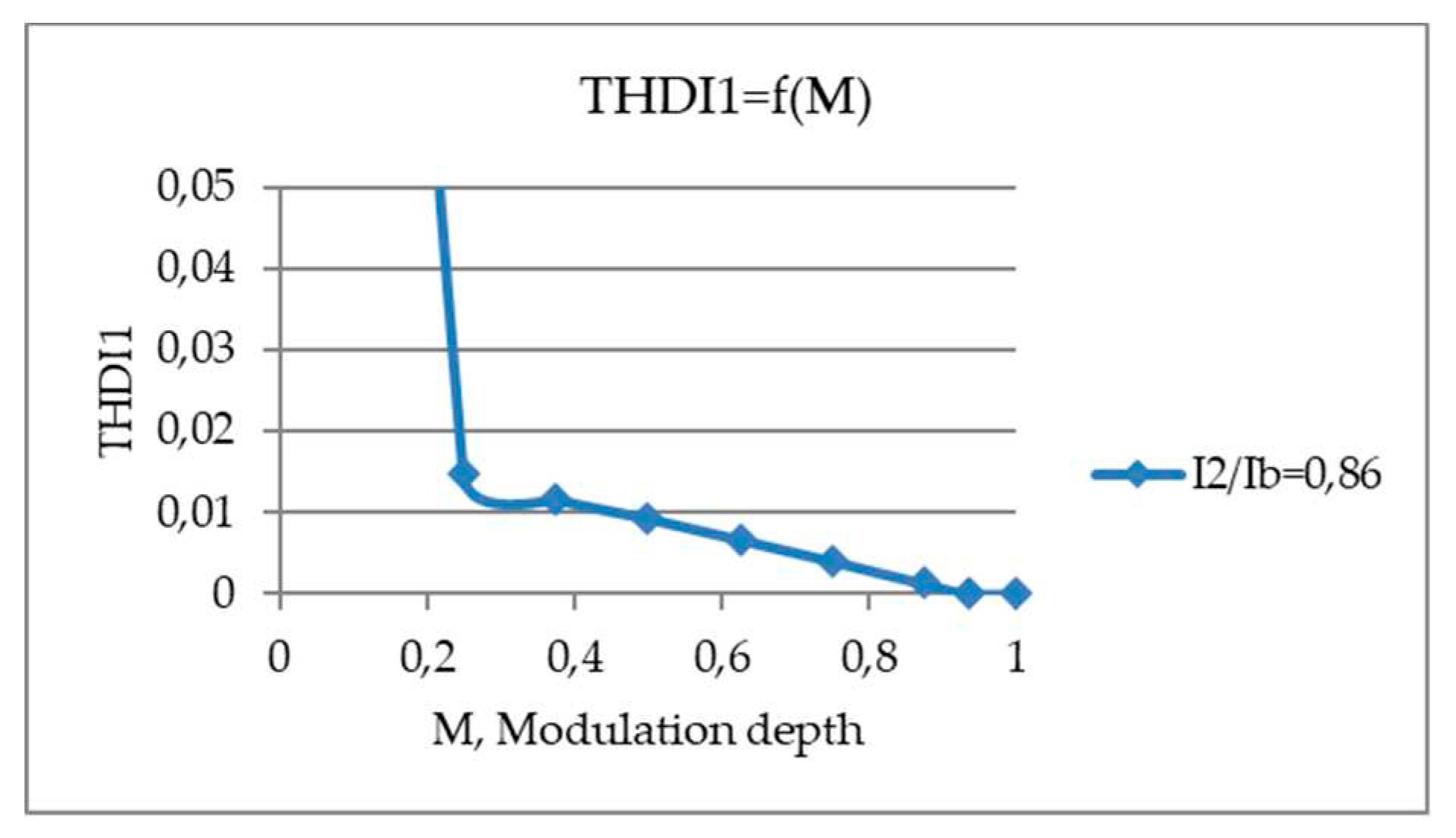
For comparison, the control and load characteristics of the regulator and the dependence of its input power factor on the modulation depth were constructed together with the results obtained in the PSIM simulation program. The operating range of the voltage increase is within M=[0.65;1], while the maximum value of the output voltage reaches 120% increase with sufficiently high quality. The constructed characteristics combined with the characteristics constructed according to the results of the simulation of the PSIM program coincided from 90% to 99%. The quality of the output voltage and input current was evaluated – the dependence of voltage and current THD on the modulation depth,
Figure 26 and
Figure 27.
An increase in the output voltage occurs at the modulation depth range M = [0.65;1], and at lower levels of modulation depth, a stabilized voltage can be obtained.
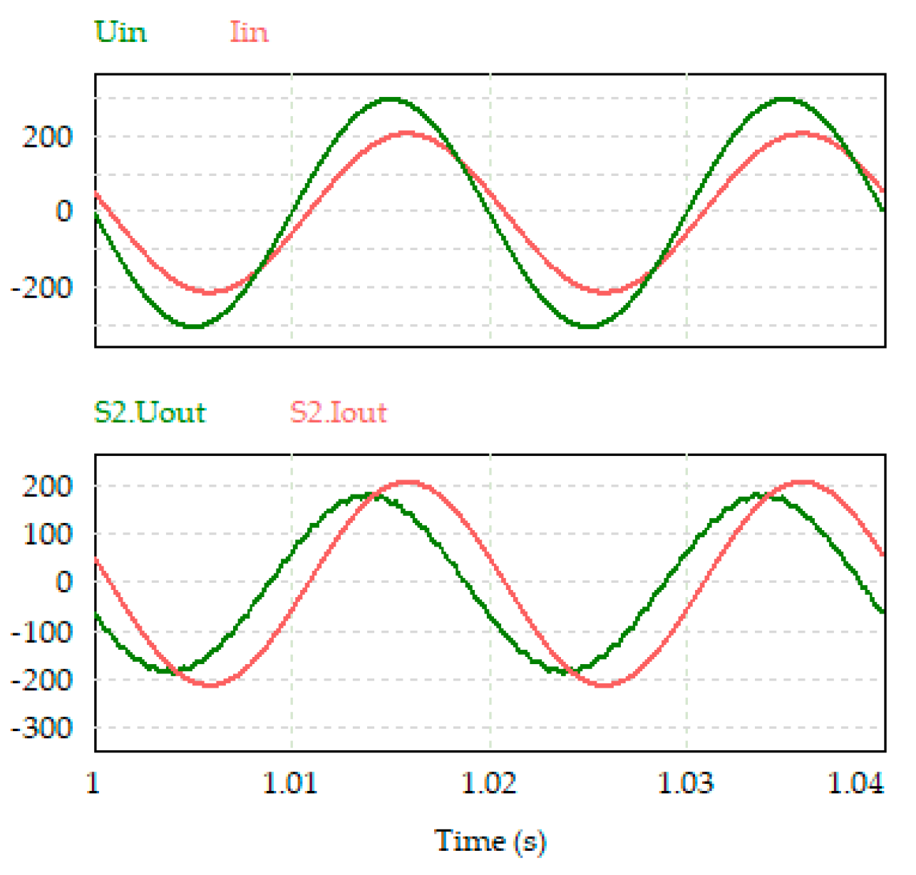
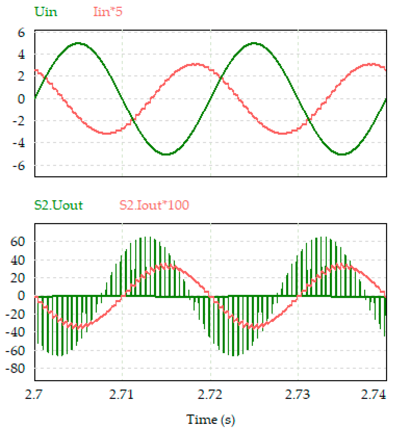
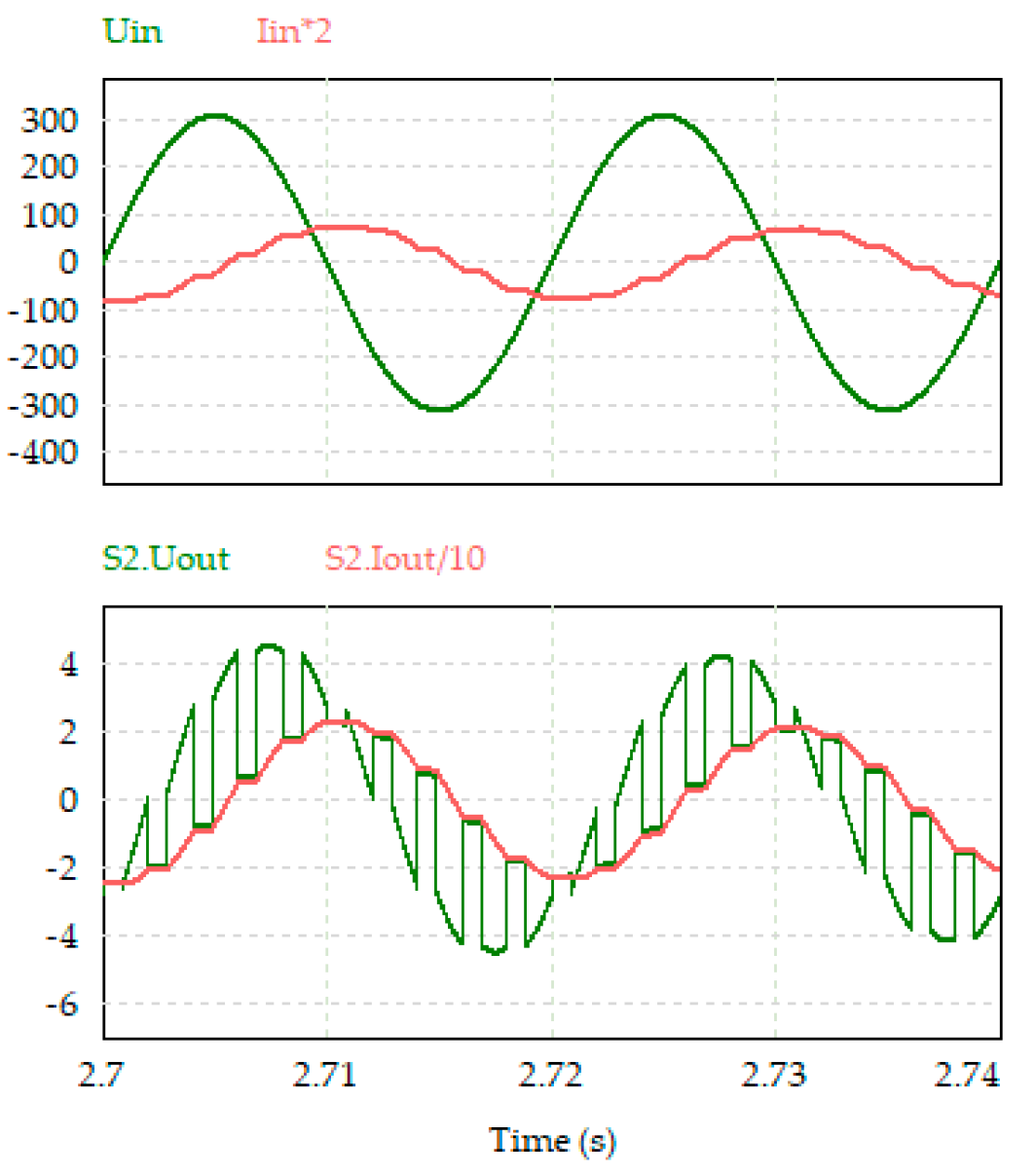
Time diagrams of input and output currents and voltages were obtained using the PSIM simulation program for a buck-boost AC voltage regulator with two AC switches
Figure 28.
The efficiency in the operating mode of the regulator reaches 0.95%,
Figure 29.
For mathematical analysis of the transformer AC voltage regulator first harmonic, the scheme shown in
Figure 30 is used. In this equivalent scheme, there is no transformer and filter capacitor C
3 as such, which do not make a major contribution to the properties of the circuit when calculating the first harmonic. This is done to reduce the order of the final matrix. Also, capacitors C
1 and C
2 are combined.
The calculation was performed for two operation modes of the circuit when the switch S
1 or S
2 is switched on. Systems of equations have been compiled for each of the modes in accordance with Kirchhoff's laws [
32].
The S
1 switch is switched on:
The S
2 switch is switched on:
A switching function was introduced that is responsible for switching from one mode to another:
where M – is the modulation depth, T – is the network period, and ω
1 is the angular frequency of the switching function.
Further, by analogy with the previous calculations, a matrix of active and reactive components of currents and voltages was compiled:
A computer model of an AC voltage transformer regulator was developed in the PSIM and oscillograms of currents and voltages were obtained,
Figure 31 [
33].
6. Calculation and modeling of AC voltage regulators with a reduced number of switches
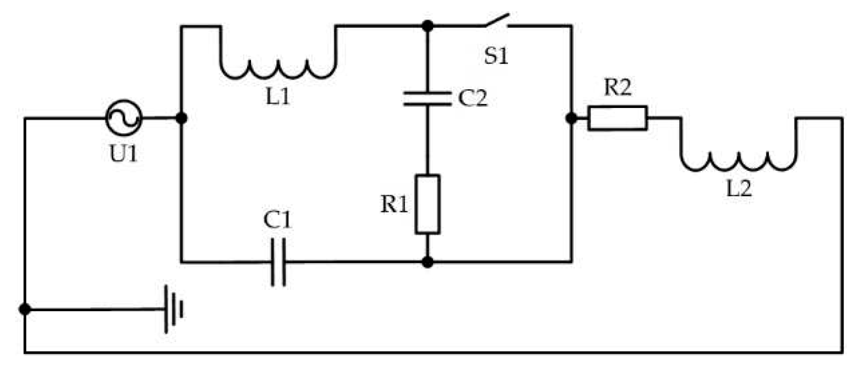
To build a mathematical model of a simplified buck-boost AC voltage regulator with a switched reactor, as before, we will use the direct method of calculating the ADE. The scheme of one phase is shown in
Figure 32.
The equations matrix of the circuit for both of its operation states using the switching function, according to the ADE method, has the form:
where
and
.
The calculation method is similar to the one given earlier. Based on its results, the effective values of the first harmonics of voltages and currents were obtained, and a family of load characteristics was constructed in
Figure 33. Where
.
The output voltage increases to at a value of M close to unity, while the maximum value of the output voltage is up to 115% greater than the input voltage at a sufficiently high voltage quality.
These characteristics are combined with the characteristics obtained in the PSIM model.
In addition, according to the data obtained during the simulation, the dependence of the input power factor on the modulation depth was obtained,
Figure 34, and the dependence of the current THD on the modulation depth was obtained,
Figure 35.
The quality of the input current and output voltage meets the requirements of State Standard 32144-2013, it is estimated by THD and is less than 5%.
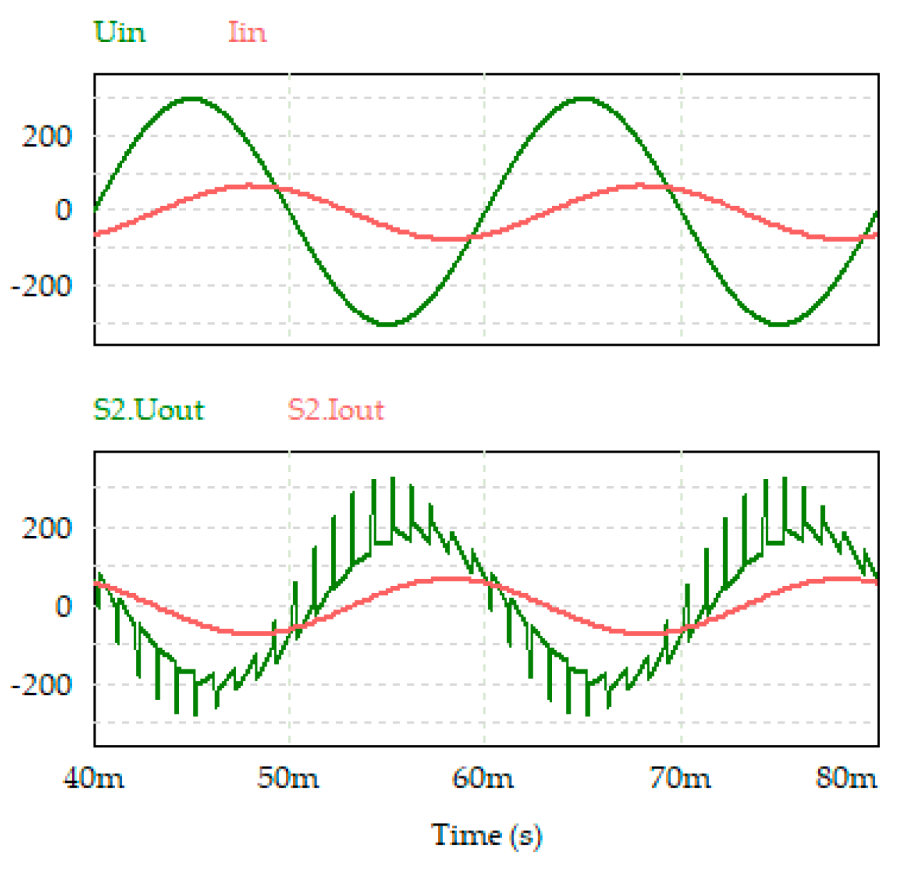
Figure 36 shows the time diagrams of currents and voltages for a simplified transistor AC voltage regulator with a switched reactor. It is worth noting that based on the plots, it can be seen that the I
lA load current is sinusoidal and does not contain high-frequency components.
The result of modeling the cascade circuit of a simplified buck-boost AC voltage regulator is shown in
Figure 37.
7. Calculation and Modeling of AC Voltage Regulators with One Complementary Pair of AC Switches for Three Phases
Voltage waveforms of a simple circuit of a buck-boost AC voltage regulator are shown in
Figure 38.
To construct a mathematical model of a regulator with a switched quasi-impedance of the power supply, a direct method of calculating the ADE was used [
34].
The equivalent scheme of the regulator one phase is shown in
Figure 39.
The equations obtained by Kirchhoff's laws for the circuit in both its operating modes have the form:
Here ψ is a switching function equal to one when the S2 switch is switched on and zero when the S1 switch is switched on.
The spectrum of the switching function is as follows:
where f – is the switching frequency,
, M – is the modulation depth. At
, the calculation is made according to the first harmonic.
As a result of the algebraization of this system of equations by the ADE method, we obtain a system of algebraic equations for the sine and cosine components of the first harmonics of variables:
where
by
,
,
According to the data obtained during the simulation in PSIM, the following characteristics were constructed: control,
Figure 40, load,
Figure 41, the dependence of the input power factor on the modulation depth,
Figure 42, for the considered circuit. The quality of the output voltage and input current is presented in the form of dependencies of their voltage THD on the modulation depth,
Figure 43, and the current THD on the modulation depth,
Figure 44.
It follows from the control characteristic that the circuit has a full control range from zero to an increased output voltage of 140-150%.
).
The load characteristics of the regulator for different modulation depths are presented. The scheme has increasing characteristics (at and ), as well as a strictly horizontal load characteristic (at ).
The quality of the output voltage and input current remains high in the operating range of operation.
According to the results obtained by the ADE method and modeling in PSIM, the control characteristics are constructed,
Figure 45, load characteristics,
Figure 46, the dependence of the input power factor on the modulation depth,
Figure 47.
The operating range of the voltage increase is within , while the maximum value of the output voltage is up to 1.6 times greater than the input with a sufficiently high quality.
The increased output voltage is achieved in the modulation depth range . At all levels of modulation depth, a stabilized voltage can be obtained.
The input power factor has a high value (> 0.8 – 1) in the range at low load currents.
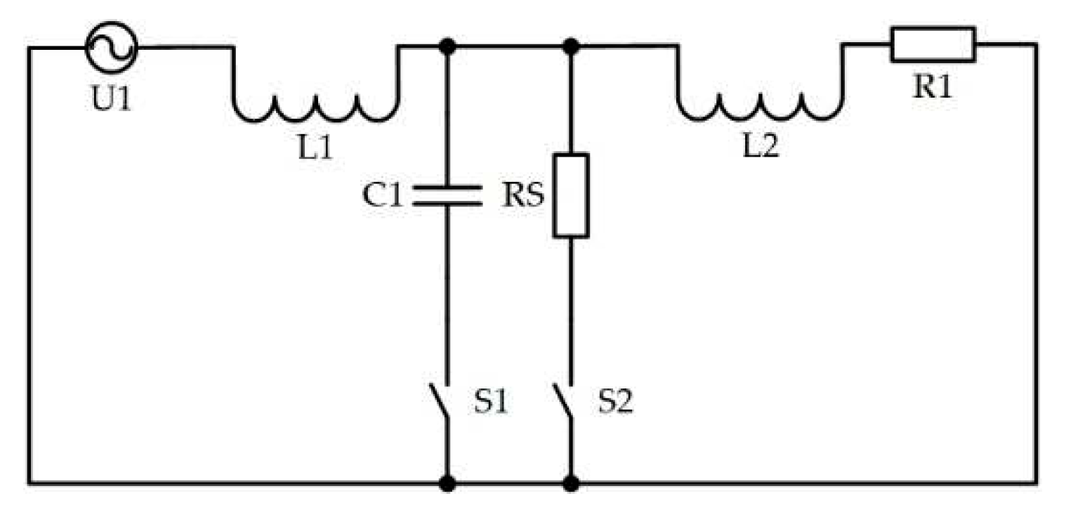
Next, the equivalent scheme of one phase of an AC voltage regulator with a low number of switches was considered,
Figure 48.
The differential equations of the circuit for both its states have the form:
Here ψ is a switching function equal to one when the switch S2 is switched on and zero when the switch S1 is switched on.
The spectrum of the switching function is as follows:
After the procedure of converting equations into an algebraic writing form, there should be no phases of currents in them. For this, we will select the active and reactive components orthogonal to each other. In the process of algebraization, we multiply the equations sequentially by cos(ωt) and sin(ωt) and average over the period of the first harmonic. As a result of the algebraization of this system of equations by the ADE method, we obtain the following system of algebraic equations, in matrix form:
For a circuit with six capacitors, U
C2(1) will be used instead of I
S(1), and the fourth and eighth columns will take the following form:
The k-th harmonic of the switching function (36) (at a switching frequency of 1000 Hz) was taken to calculate the higher harmonics.
Where M – is the modulation depth.
Differential equations of the system with switches S
1 or S
2 switched on, respectively:
As a result of algebraization of equations system by the ADE method, we obtain the following system of equations:
According to the calculation results, the following characteristics are constructed: control,
Figure 49, load,
Figure 50. They are combined with the characteristics obtained in the PSIM model.
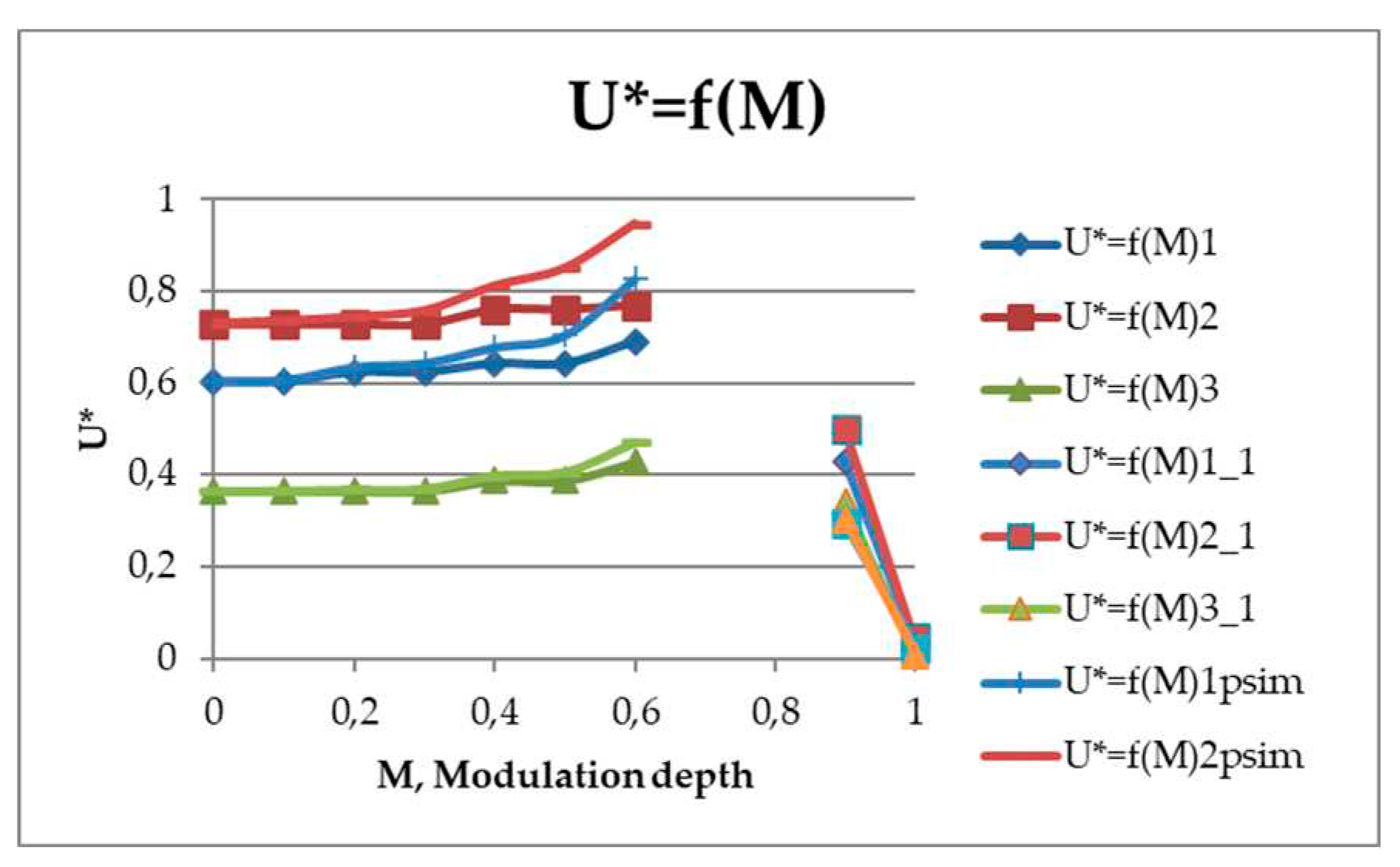
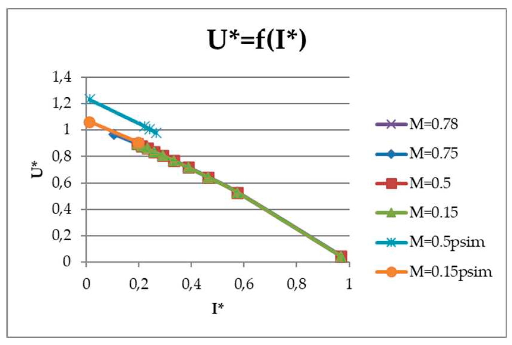
Figure 51 and
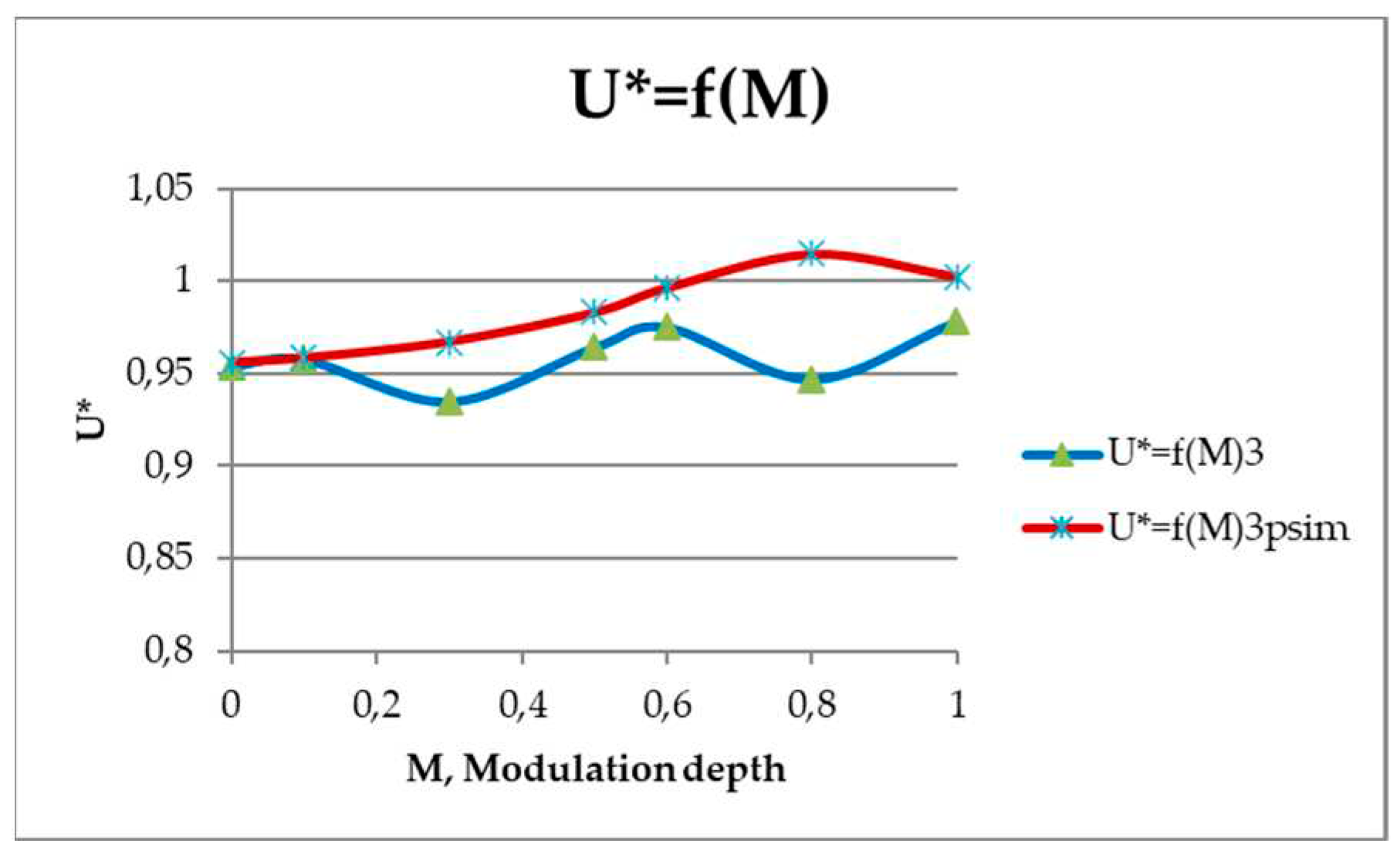
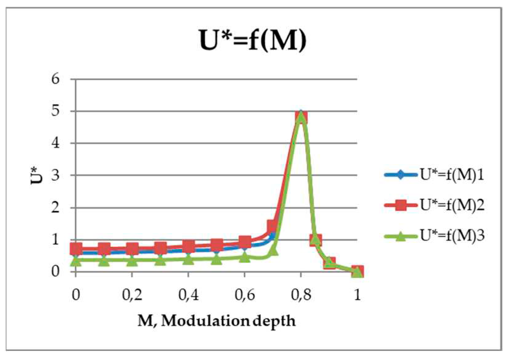
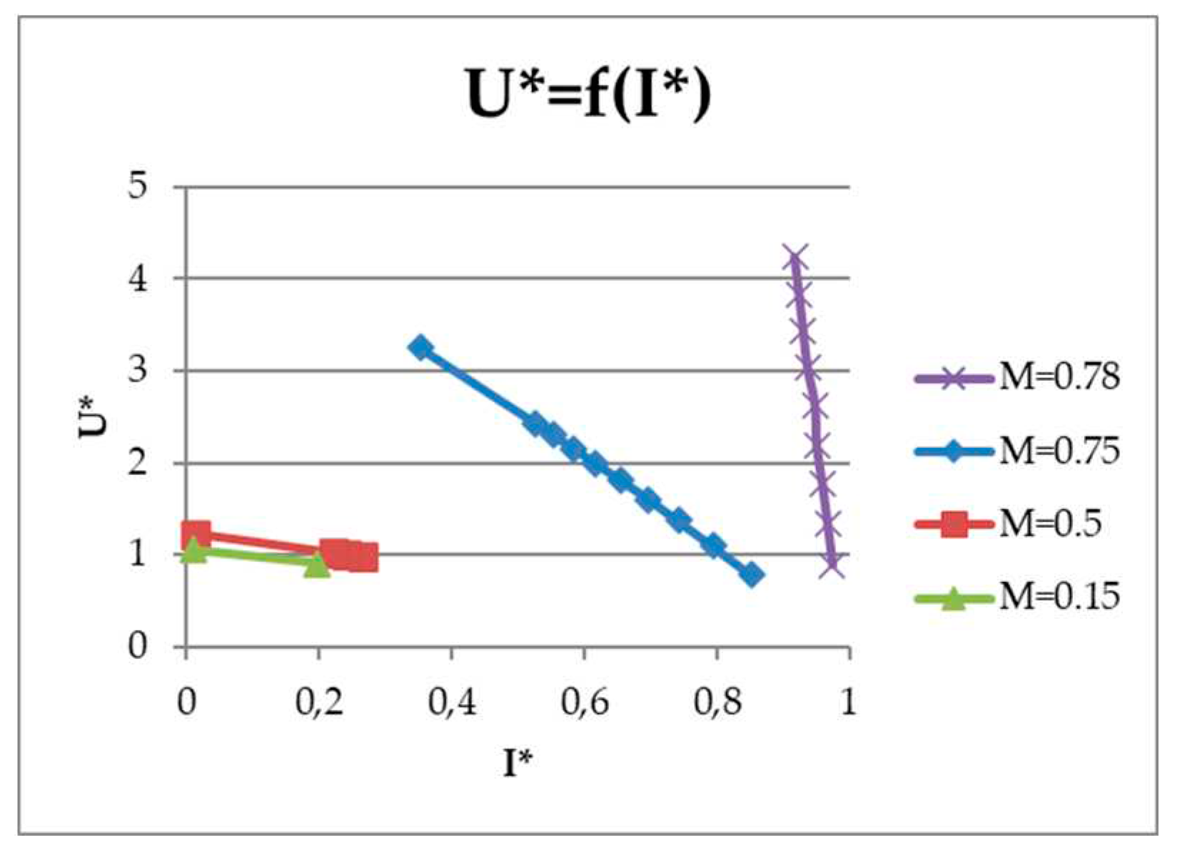
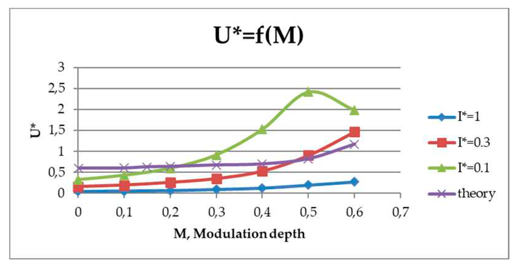
Figure 52 show similar characteristics, but for AC voltage regulator with six capacitors. Where U*=f(M)1,2,3 are the control characteristics at I*=0.5...0.38...0.72, respectively (for a circuit with three capacitors) and 0.047...0.029...0.114 (for a circuit with six capacitors). In this case, U*=U
out/U
in, and I*=I
out/I
base, whereas I
base=U
in/ωL
1.
At small values of modulation M, there is a discrepancy between the simulation results and the theoretical ones. This indicates the need to further adjust the calculation taking into account the higher harmonics of the switching function.
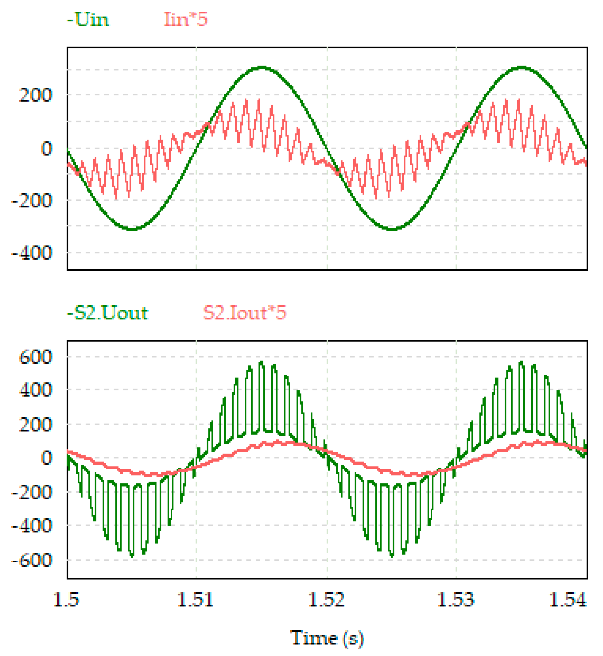
The voltage and currents of the AC voltage regulator with a low number of switches obtained in the PSIM are shown in
Figure 53 and
Figure 54.
The control and load characteristics of the AC voltage regulator with a low number of switches are shown in
Figure 55 and
Figure 56. The regulator allows you to get an increased output voltage up to 420%. In the operating area, the converter has a full range of regulation. In the zone from M=0 to M=0.6, the control characteristics are close to horizontal, then they increase. For the rest of the interval, the control characteristics gradually decrease.
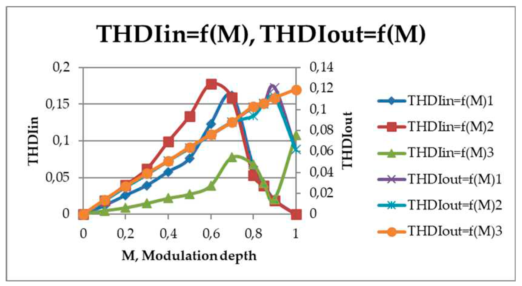
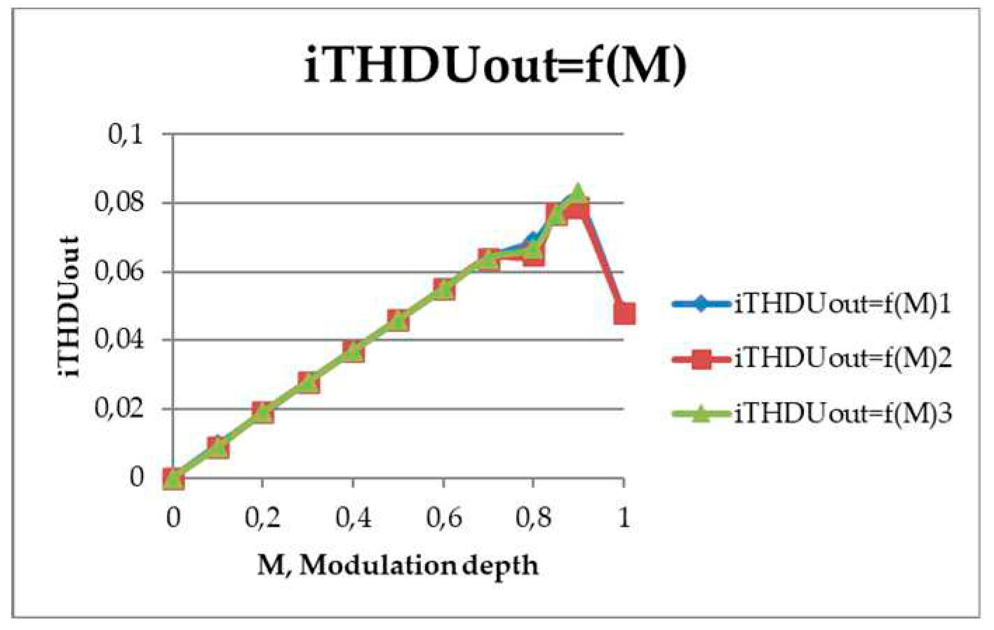
The quality of the input, output current and output voltage is estimated by the THD and the integral THD of the voltage. The characteristics are shown in
Figure 57 and
Figure 58.
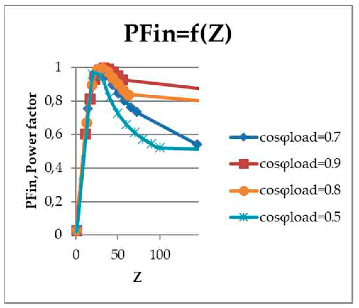
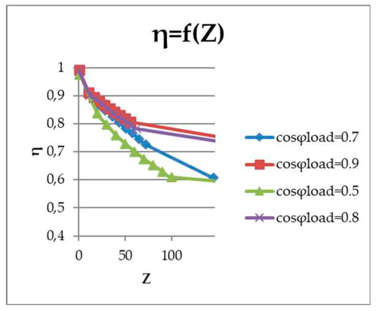
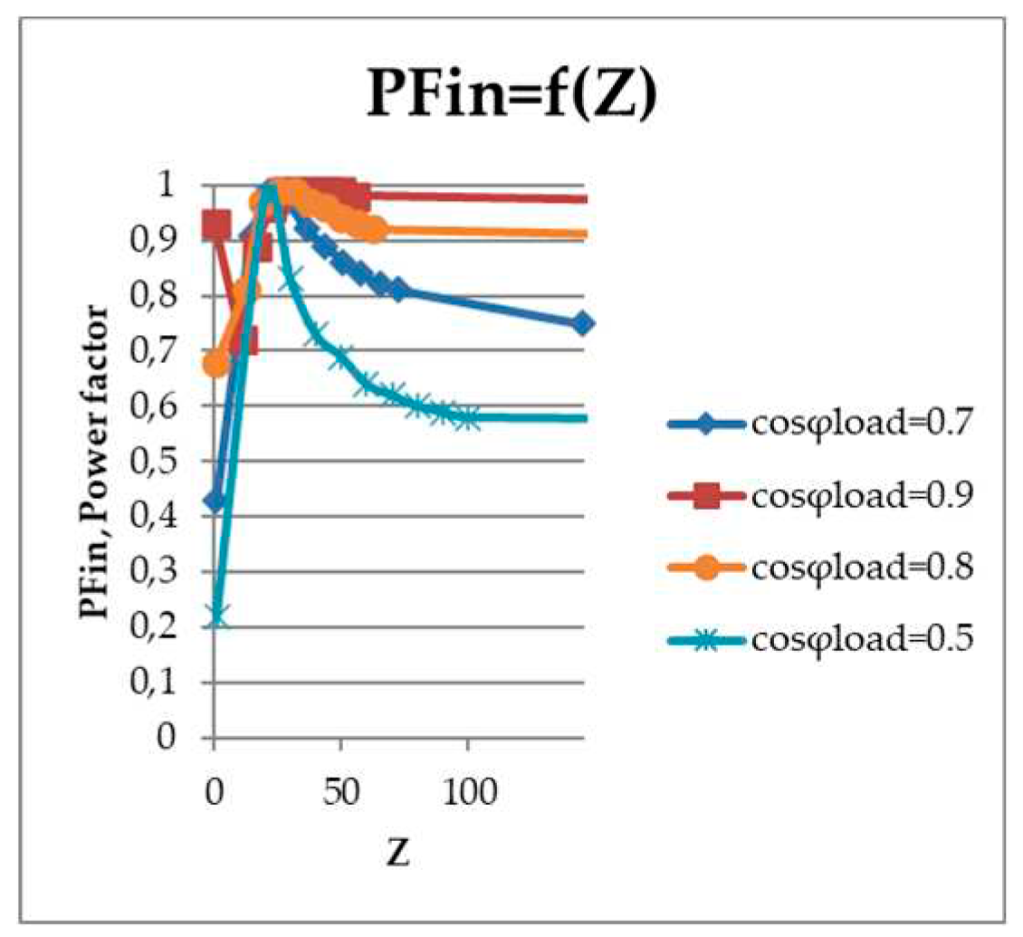
The power loss of an AC voltage regulator with a low number of switches was 42 watts per 736 watts of output power at a switching frequency equal to 1 kHz. The calculation took into account switching and conduction losses in transistors and diodes, as well as the power dissipation of capacitors. Thus, the efficiency of the regulator was 95%. The dependence of the input power factor and the dependence of the efficiency on the impedance are shown in
Figure 59,
Figure 60, respectively.
It can be seen from the graphs that such a regulator is a buck.
The quality of the input, output current and output voltage is estimated by their THD,
Figure 61.
The proposed AC voltage regulator with a low number of switches was compared with a three-phase AC-AC Ćuk converter [
35]. It is revealed that the AC voltage regulator with a low number of switches surpasses the opponent in the following indicators. According to the gain factor of the output voltage, the proposed AC voltage regulator with a low number of switches had this coefficient of 4.24, versus 2.01 for the Ćuk converter. Comparing the magnitude of the reactive power of the capacitors in the proposed scheme, there is a noticeable decrease in comparison with a buck-boost AC voltage regulator with a switched quasi-impedance of the power supply [
36] and a three-phase AC-AC Ćuk converter (Table I).
The calculation results presented in
Table 2 were also obtained, which shows the ratio of the effective values of the higher harmonics to the effective value of the first harmonic of the output current [
37].
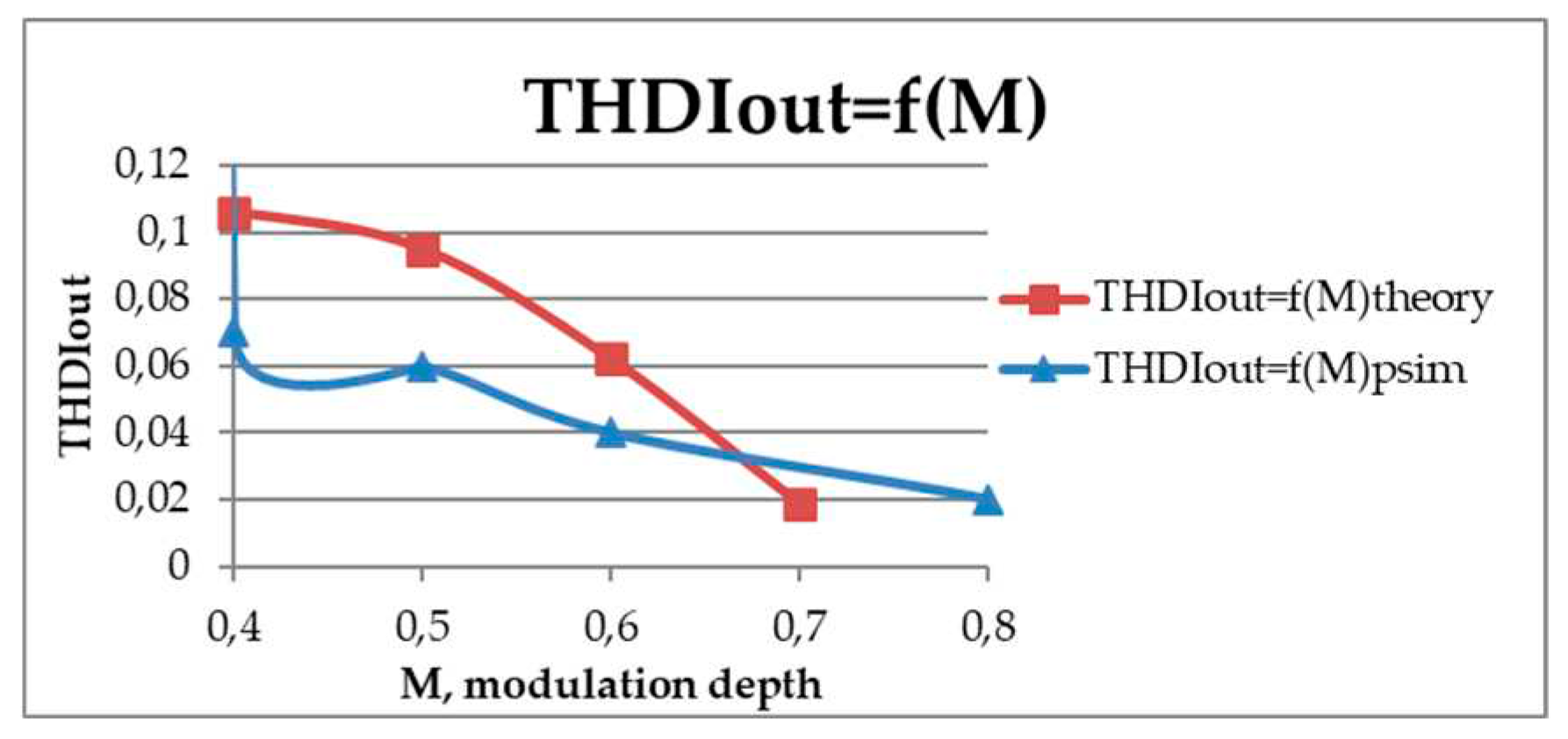
From the results presented above, it can be seen that the proportion of higher harmonics in the output current is less than 10%, while the calculation data coincide with the simulation data at M < 0.9.
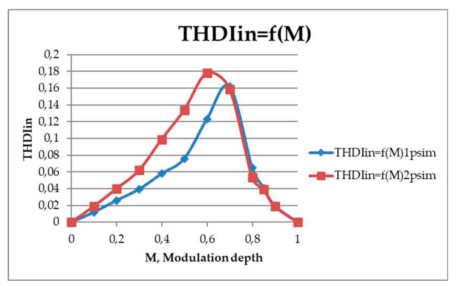
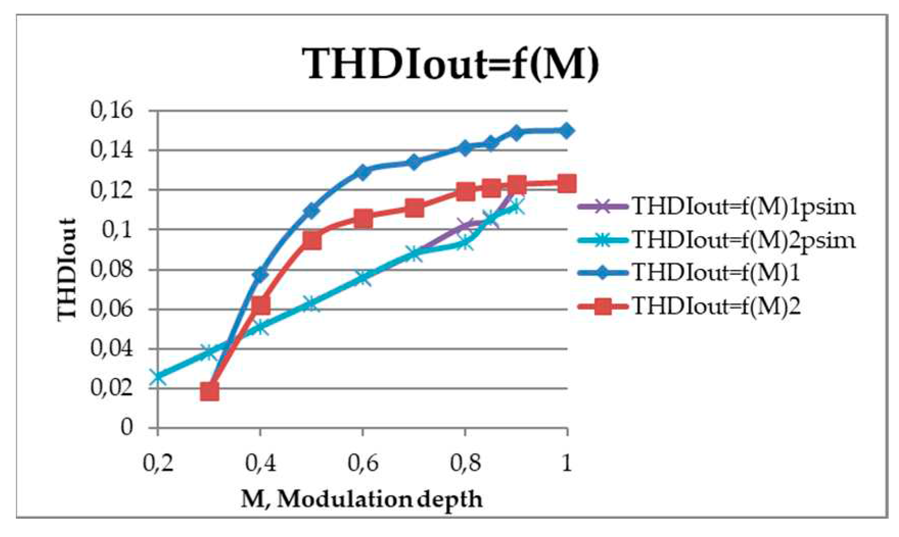
The quality analysis of the regulator currents was carried out at a fixed value of the switching frequency of the transistors,
Figure 62 and
Figure 63 (f
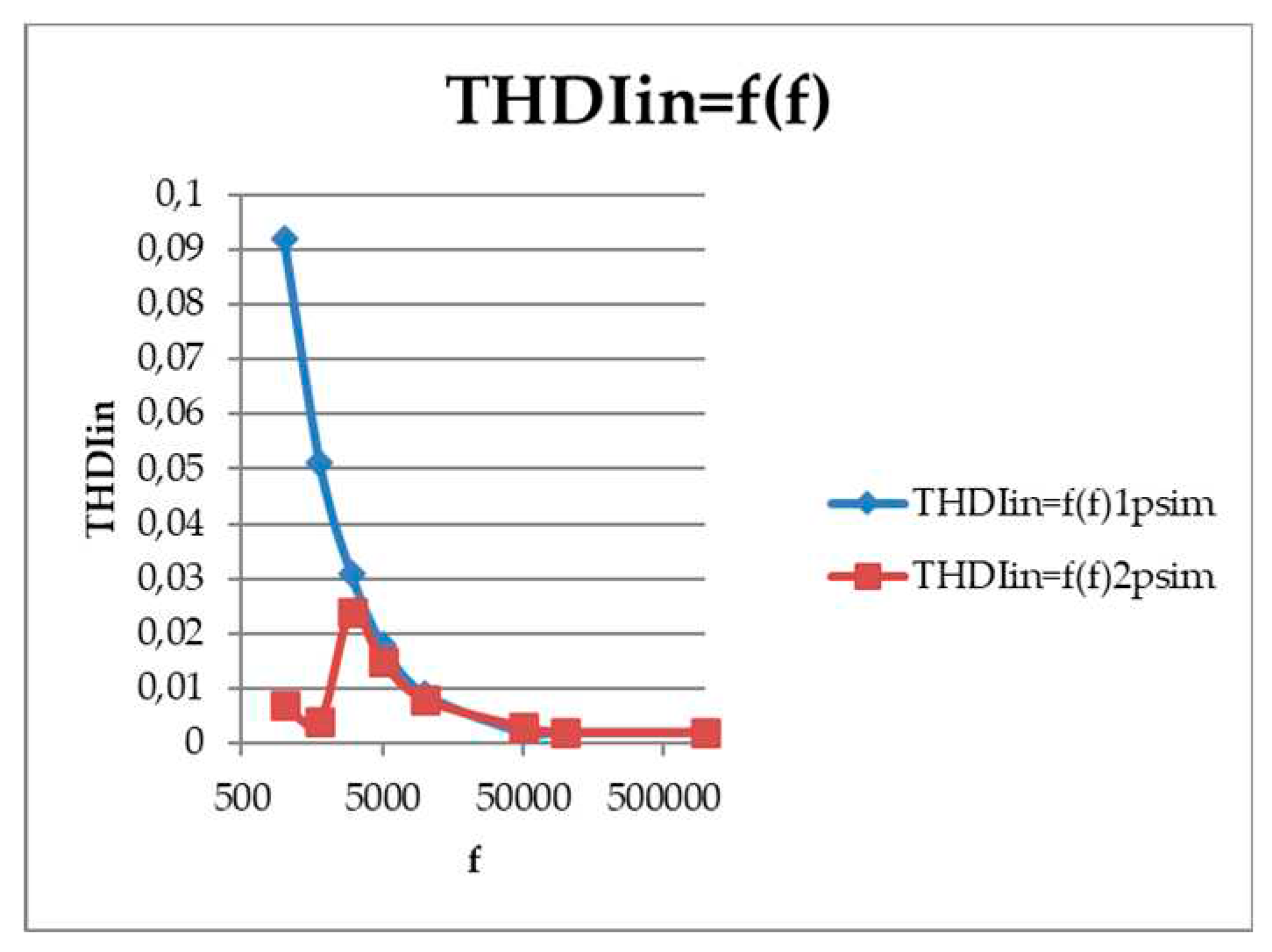
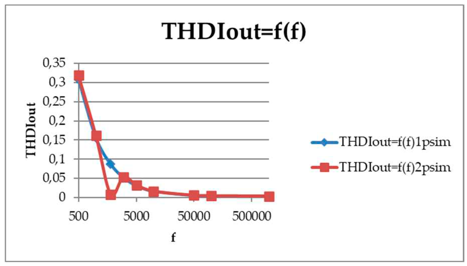
sw = 1.8 kHz). The quality characteristics of the input and output current of an AC voltage regulator with a low number of switches were obtained. The frequency range was chosen from 500 Hz to 1 MHz. The result of the analysis is shown in
Figure 64 and
Figure 65. Starting from 2 kHz, the harmonic coefficient for both input and output current does not exceed 5%, which indicates a high quality of the modulated current.
To construct a mathematical model of an AC voltage regulator with a low number of switches with a transformer, we will use the direct method of calculating the ADE [
38].
The equivalent circuit of the regulator one phase is similar to that of an AC voltage regulator with a low number of switches, only there is no RS resistance, shown in
Figure 66.
The differential equations of the circuit for both its states have the form:
Here ψ is a switching function equal to one when the switch S2 is switched on and zero when the switch S1 is switched on.
The spectrum of the switching function is as follows:
In the process of algebraization of differential equations, the following results were obtained:
Figure 67, together with the results in the PSIM, shows the THD of the output current. The range of modulation depth is limited by the results of the calculation by the ADE method, since large discrepancies were obtained at the boundary values caused by the assumptions of the calculation method.
In the course of the study, the dependences of the input power factor on the modulation depth were obtained (
Figure 68), the dependence of the input power shift on the load impedance (
Figure 69), control characteristics (
Figure 70). Parameters of the investigated model: the switching frequency is 1 kHz, the capacitance of the capacitors is 10 uF, the inductance of the primary and secondary windings of the transformer is 100 mH and 500 mH, respectively.
The input power factor is obtained at a stable load current of 3 A. The converter behaves as a reactive power compensator over almost the entire control range, creating a capacitive current in the network.
When the load impedance changes, the input power factor remains stable, closer to the short-circuit mode, while a noticeable difference in indicators is observed.
Voltage regulation in this converter is carried out in the range M: 0-0.6. In the mode close to idling, the maximum increase in the output voltage was noticeable, which exceeded the input voltage by 250%. Here are three graphs with different average load current (in relative units), relative to the base value of Ibase=Uin/ωL. In addition, a graph with a calculation using the ADE method is given for comparison.
Figure 71 shows diagrams of currents and voltages of an AC voltage transformer regulator with a low number of switches.
8. Experiment of an AC voltage regulator with a full number of switches
The operation of a two-zone AC voltage regulator with a capacitor voltage divider was analyzed [
39,
40]. The photo is not given, the regulator was assembled without a design.
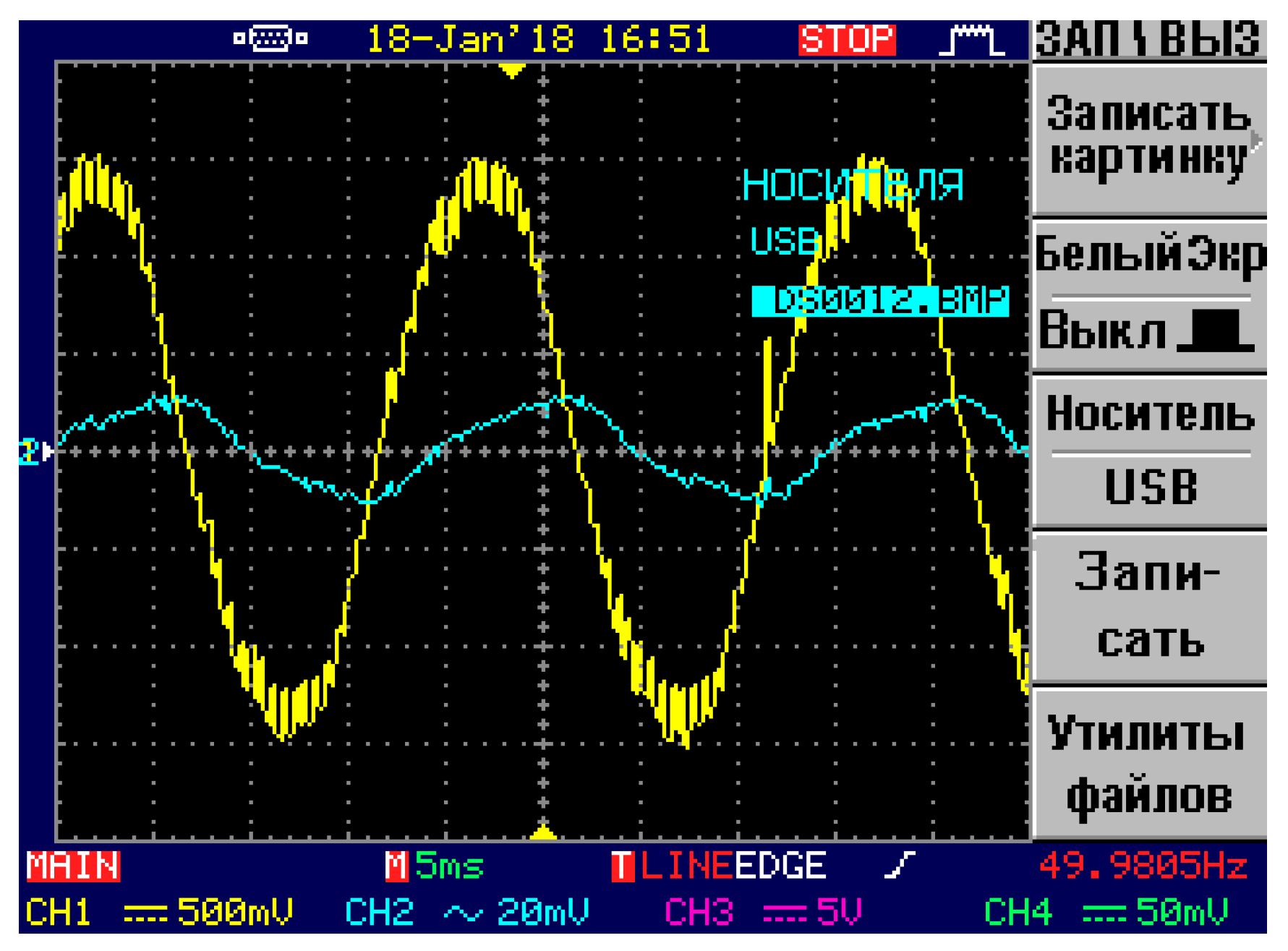
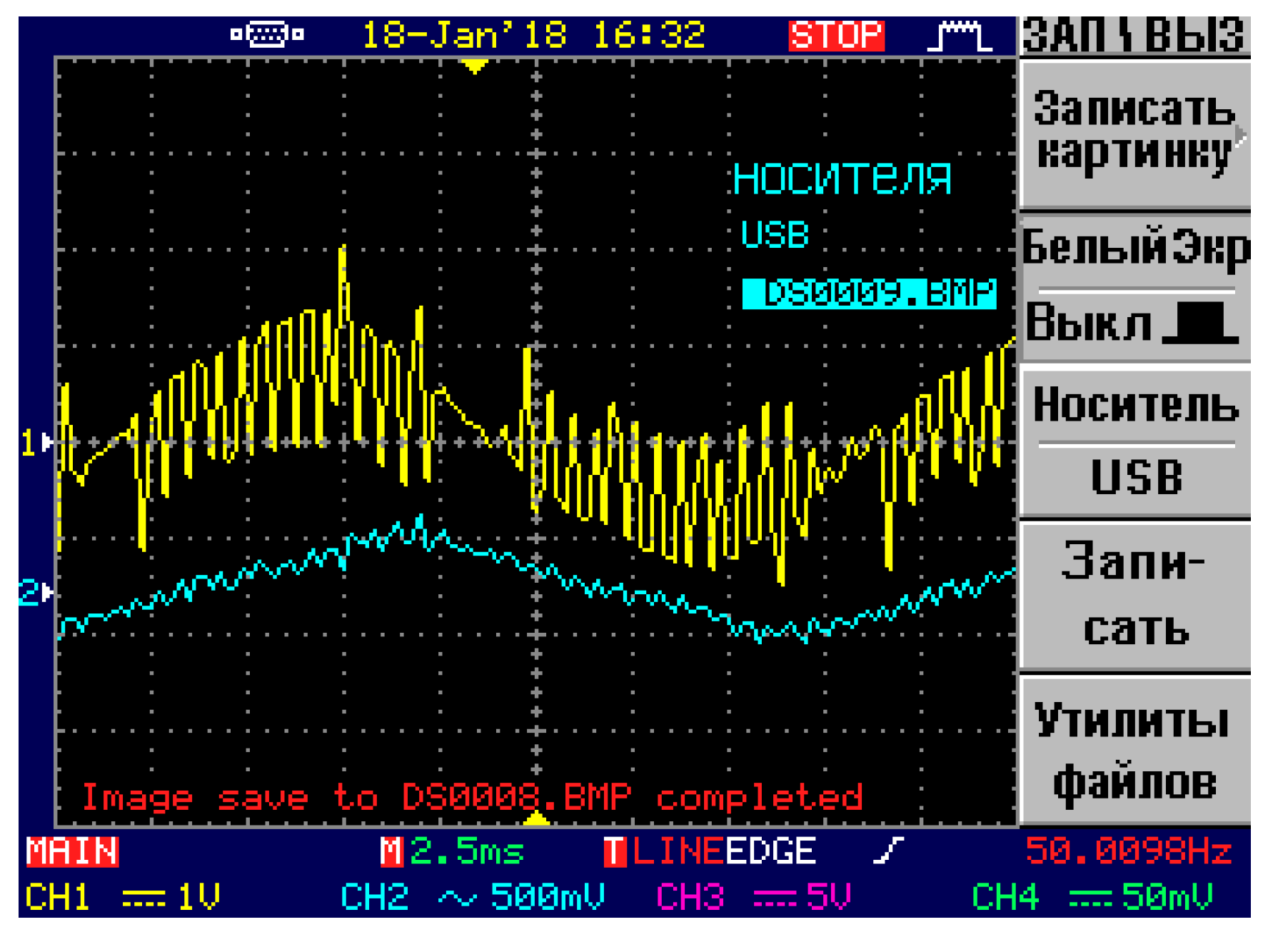
An active-inductive load was connected to the converter. The output current and voltage waveforms are shown in
Figure 72 in the lower control zone and
Figure 73 in the upper control zone.
This was an example of the multi-zone AC voltage regulator operation, where thyristors were used as switches. When using transistors, it was possible to raise the switching frequency.
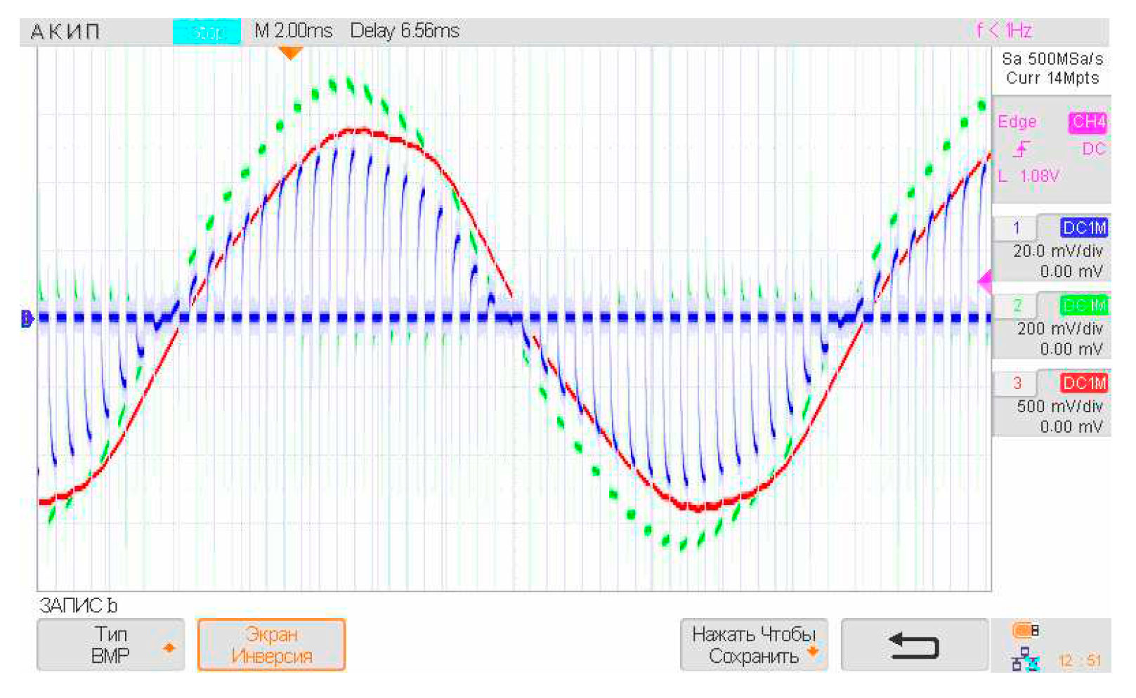
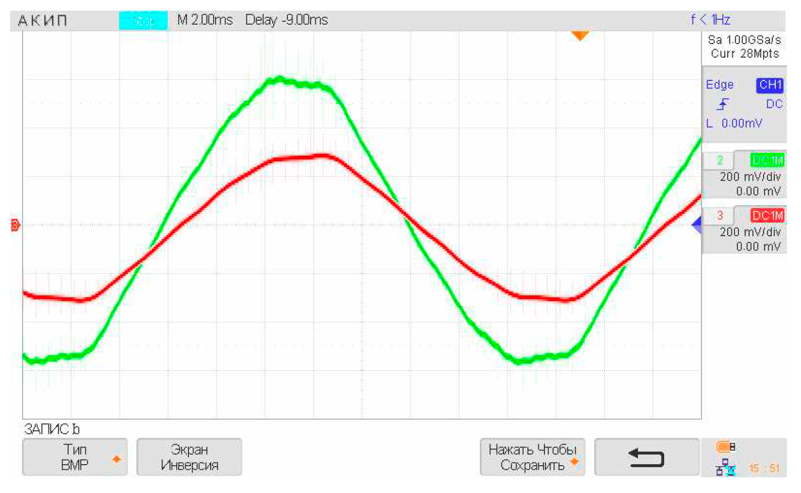
At a modulation depth of 0.25, the control signal of the first zone is an average value with a fill factor of 50%. The shape of the input and output voltage with current is shown in
Figure 74. The value of the maximum instantaneous value of the load voltage is the voltage of the capacitor, which divides the supply voltage in half and compensates for reactive power.
The voltage and current of the capacitors are ahead of the input voltage. The voltage on the capacitors is halved compared to the input voltage (
Figure 75). The capacitor current has a basic low-frequency harmonic (
Figure 76). The value of the capacitor current is determined by the depth of modulation of the converter, the supply network and the value of the capacitance.
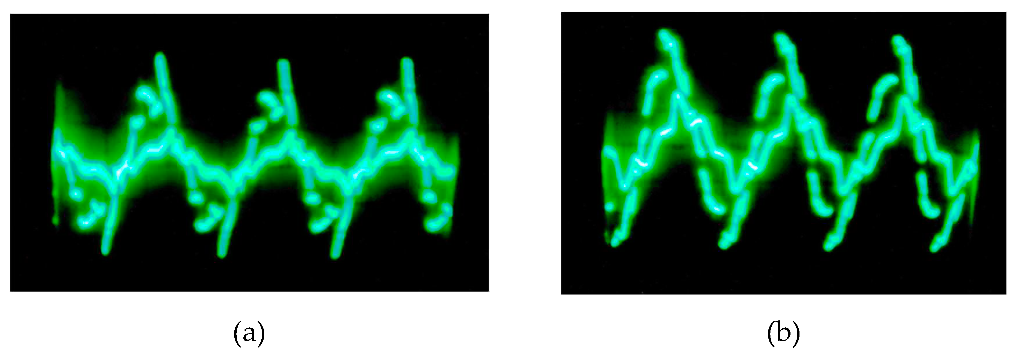
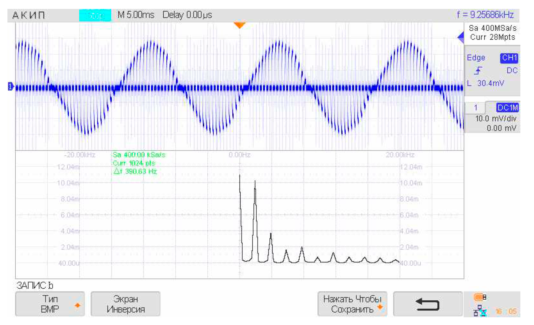
In the spectrum of the load current, the main contribution is made by low-frequency components, and subharmonics are multiples of the switching frequency of 1 kHz at a resistive load (
Figure 77). The converter control system uses a dead time of 400 ps, originally embedded in the driver circuit.
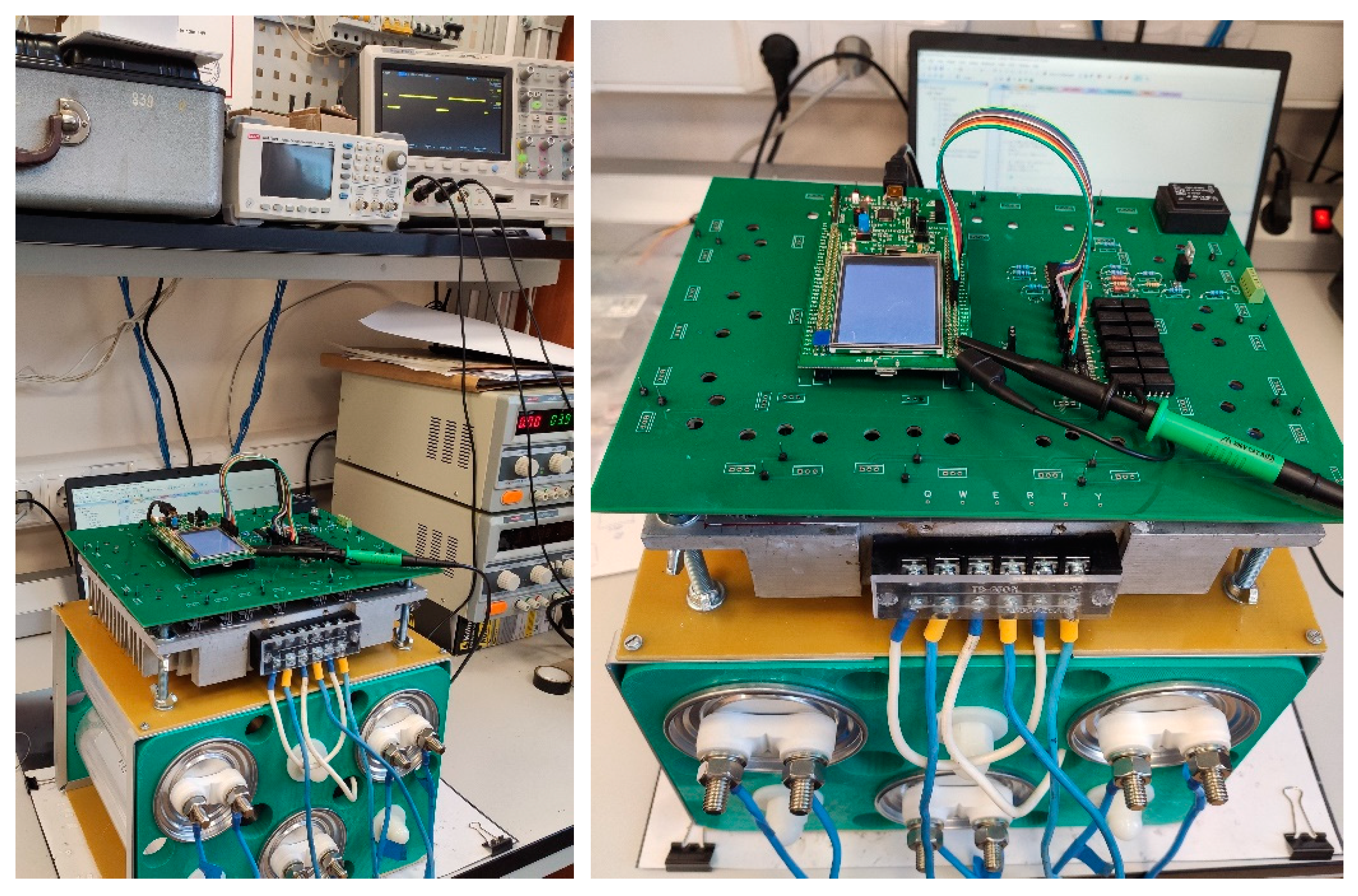
The power board and the control system were made on the same board. The photo of the layout is shown in
Figure 78. The model uses transistors: G4BC30UD (U
ce=600 V, I
c=12A); drivers: SI8231BB-D-IS; DC-DC power supplies: SBT01L-09 capacitors: B32373A4207J080 (capacity C=200uF, U
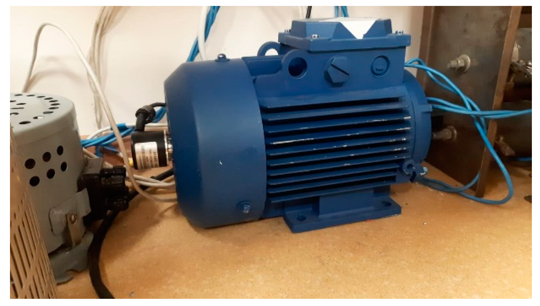
AC=480V). An 80 V2 IM1081 AIR engine (2.2kW) with a sensor was used as a load,
Figure 79.
The cost of a two-zone three-phase AC voltage regulator was 2,600 rubles/kW, which is almost two times less than the leading firms in the production of soft starters.
An example of the operation of a buck-boost AC voltage regulator is shown in
Figure 80 and
Figure 81. The experimental layout of the AC voltage regulator was started at different input and output parameters. When operating at the input voltage U
in = 33V. The output voltage was increased to 39 V. At an input voltage of 18.9 V, the output voltage was increased to 23.6 V. The voltage and load current of the regulator are shown in
Figure 80. Oscillograms with a smaller inductance L
2 = 1.4MH and larger capacitances C
1 = 160uF, C
2=8uF were also taken. The results of this experiment are shown in
Figure 81.
Experiment of an AC voltage regulator with one complementary pair of three-phase alternating current switches
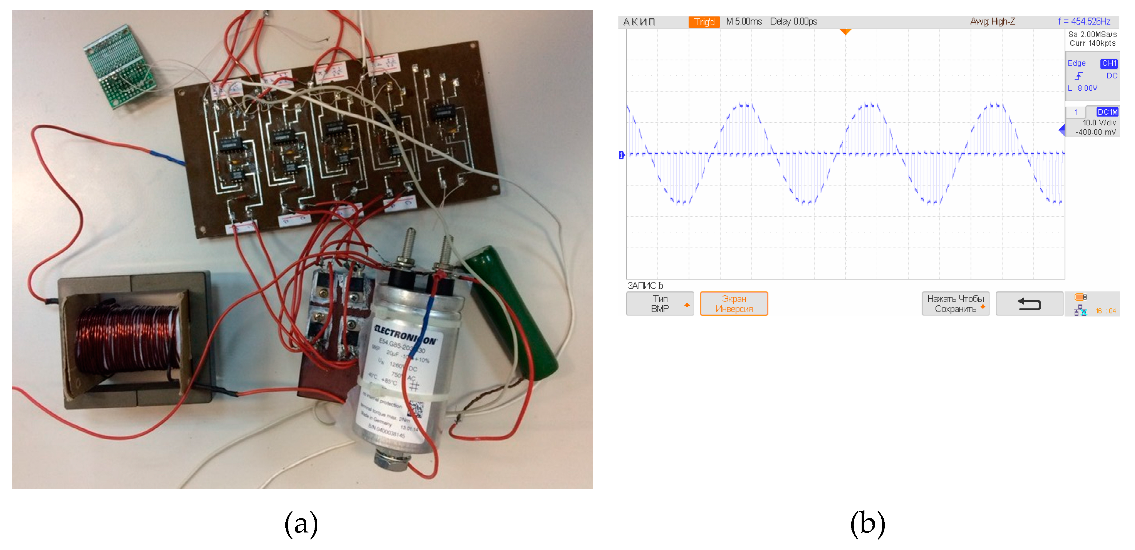
An experimental model of a single phase of an AC voltage regulator with a switched quasi-impedance of the power supply was assembled. The photo and simulation results are shown in
Figure 82.
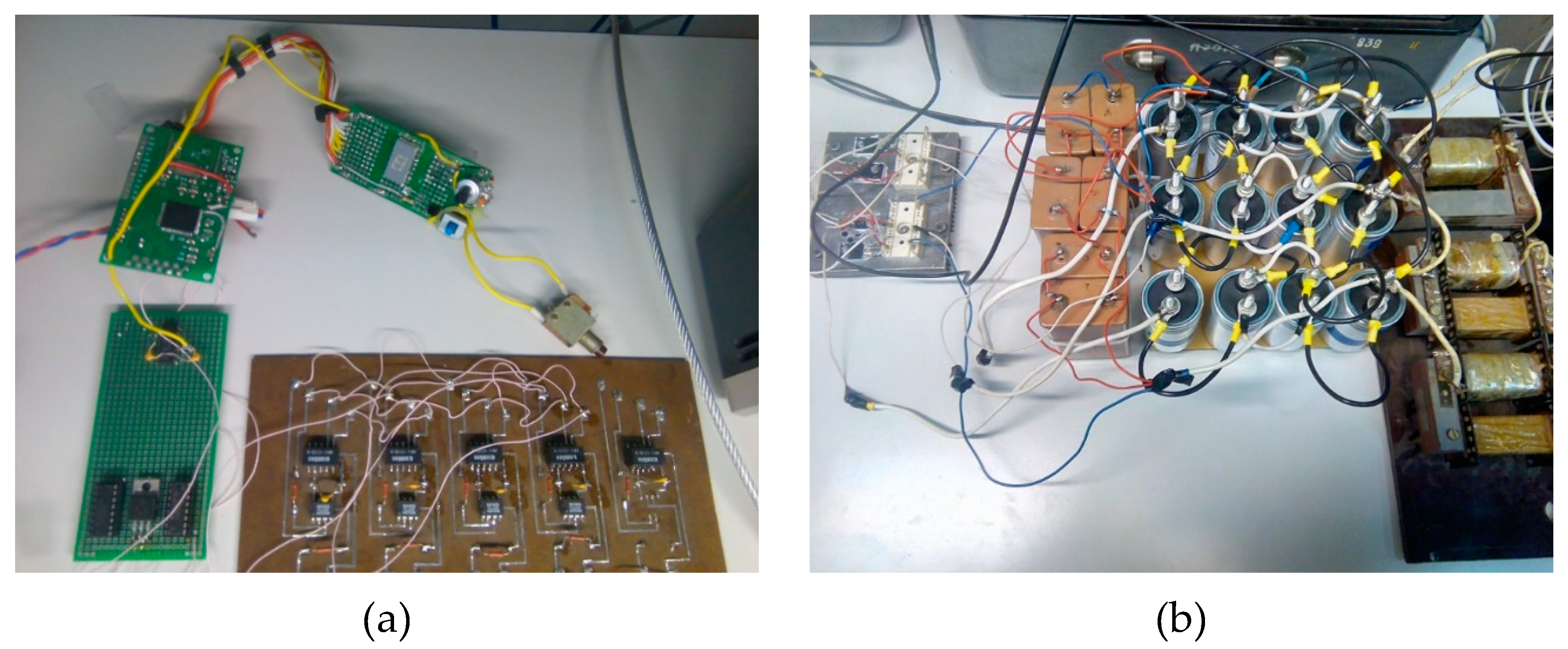
A layout of an AC voltage regulator with a low number of switches with a digital control system based on the Atmel AVR Atmega 128A microcontroller was assembled [
41,
42,
43,
44,
45,
46,
47,
48,
49,
50].
Figure 83 shows the proposed system.
In addition, monitoring of the output voltage level was required in the regulator. Voltage monitoring was performed by the program function, the voltage signal was obtained from the voltage sensor and fed to the processor input. This auto-regulation system used the PI-law of regulation.
An example of the AC voltage regulator with a low number of switches operation is shown in
Figure 84. The experimental layout of the AC voltage regulator operated on an active-inductive load. The capacitors of the converter are selected with a capacity of C = 20 uF, with the possibility of increasing to 80 uF (by connecting in parallel), the input choke was L = 812 uH.
On the oscillograms of currents and voltages, the spectrum of output and input current is given, where it is shown that the share of the high-frequency component of the output current is less than 10% [
51,
52,
53,
54].
9. Discussion and conclusions
The considered AC voltage regulators can ultimately be divided into two types, according to the application areas. While in the paper the separation was made by the number of semiconductor switches, it was determined that low number of switches circuits can be more applicable as AC voltage stabilizers. Whereas soft starters are also an integral part of the application of AC voltage regulators, where the motor performs as the load. With direct start-up, the starting currents can reach a tenfold excess, which negatively affects the mechanism and the motor windings. Common thyristor regulators of AC voltage with counter-parallel connection of thyristors are one of the advantageous ways to start the engine. But there are inherent disadvantages. Thyristor AC voltage regulators have poor quality output voltage and current. The proposed multi-zone AC voltage regulators solve this problem. So, in comparison with the classic thyristor AC voltage regulator, the quality is increased up to 6 times, as can be seen from the THD, single-zone version. As for the number of semiconductor switches. Then there are more of them in multi-zone AC voltage regulators, but the class of thyristors decreases in proportion to the number of zones, so for a classical thyristor AC voltage regulator at 1000V, the class of thyristors will be the tenth, whereas in a ten-zone thyristor AC voltage regulator, the class will be the first. Such a solution gives a more flexible choice of devices. And the proposed AC voltage regulator with the combined connection of capacitors will increase reliability by balancing the voltage on the capacitors and reserving the used capacitors.
As for AC voltage stabilizers, at present the market of manufacturers of such devices is quite large, here we can distinguish such firms as Voto, Solby, Resanta, Energia, Volt, Zord, IEK, Powerman, EKF, Elitech, Prodgy, TCC, Suntek, Rider, Wusley, TDM, Elitech, Genstab, N-Power, Ortea, Vega, Varat. In this regard, a competitive solution is needed – a small number of transistors used in regulators. Such solutions were presented in this paper, while some allow increasing the output voltage up to 4 times, which significantly increases the range of drawdowns and overvoltages. Some of the devices were assembled and experiments were carried out to confirm the operability of the proposed ideas.
Author Contributions
Conceptualization, A.U.; methodology, A.U., E.K.; software, E.K.; validation, E.G., A.M.; formal analysis, A.U.; investigation, A.U., E.K.; resources, A.U., E.K.; data curation, A.U.; writing—original draft preparation, A.U.; writing—review and editing, A.U., E.K.; visualization, A.U.; supervision, E.G.; project administration, A.U.; funding acquisition, A.U., E.G., E.K. All authors have read and agreed to the published version of the manuscript.”
Funding
The work was carried out with the support of the Russian Science Foundation № 23-29-10055,
https://rscf.ru/project/23-29-10055/, with the support of Government of Novosibirsk Region, agreement № r-67.
Data Availability Statement
The data presented in this study are available on request from the corresponding author. The data are not publicly available due to privacy issues.
Conflicts of Interest
The authors declare no conflict of interest.
References
- Sazhenkov, V. Soft starters and frequency converters. – Schneider Electric Technical Collection, – №38, 2011. (in Russian).
- Brescia, E. , Vergallo P., Celik I. Parameter Identification of PMSMs Considering VSI Nonlinearity with Coupled Adaline NNs //2023 IEEE 3rd International Conference on Power, Electronics and Computer Applications (ICPECA). – IEEE, 2023. – pp. 259-265. [CrossRef]
- Brescia, E. et al. Automated Parameter Identification of SPMSMs Based on Two Steady States Using Cloud Computing Resources //2021 International Conference on Electrical, Computer and Energy Technologies (ICECET). – IEEE, 2021. – pp. 1-6. [CrossRef]
- Brescia, E. et al. Cogging Torque Suppression of Modular Permanent Magnet Machines Using a Semi-Analytical Approach and Artificial Intelligence //IEEE Access. – 2023. [CrossRef]
- Brahmbhatt, Hiren, et al. "A Novel Control Strategy of Thyristorised Medium Voltage Soft Starter for Induction Motor Drives," 1st International Conference on Advances in Energy Conversion Technologies (ICAECT 2010), Jan 07–10, 2010, pp. 1–5.
- Lakhani, H. et al. Design and simulation of controller for medium voltage thyristorised induction motor soft starter //2009 International Conference for Technical Postgraduates (TECHPOS). – IEEE, 2009. – pp. 1-5. [CrossRef]
- Wu, J. , Zhao R., Shang Z. The design of soft starter for AC motors based on single neuron PI regulator //2006 6th World Congress on Intelligent Control and Automation. – IEEE, 2006. – vol. 1. – pp. 3009-3013. [CrossRef]
- 8. Chen X., Li H. Research and Simulation of Electromagnetic Voltage-Regulated Soft Starter Based on Predictive Control //MATEC Web of Conferences. – EDP Sciences, 2018. – vol. 232. – pp. 04040. [CrossRef]
- Jakovlev, I. and others, “Mathematical model of operation of an asynchronous motor with a soft-start device based on an AC voltage regulator” // Energy systems. – 2022. – vol. 7. – №. 4. – pp. 54-68. (in Russian).
- Lopatkin, N. , Zinoviev G., Kharitonov S. Inverter Asynchronous Electric Drive System with PAM and PWM Control //2022 International Ural Conference on Electrical Power Engineering (UralCon). – IEEE, 2022. – pp. 341-346. [CrossRef]
- Zinoviev G., S. Development of set of electric energy quality factors //2018 XIV International Scientific-Technical Conference on Actual Problems of Electronics Instrument Engineering (APEIE). – IEEE, 2018. – pp. 44-47. [CrossRef]
- Zinoviev, G. Definition of contributions of nonlinear consumers in total distortion of power line current //2016 11th International Forum on Strategic Technology (IFOST). – IEEE, 2016. – pp. 154-156. [CrossRef]
- Makarov, D. , Zinoviev G., Kharitonov S. Analytical analysis of the variable frequency power system with shunt-connected voltage regulator //2015 International Conference on Electrical Drives and Power Electronics (EDPE). – IEEE, 2015. – pp. 482-487. [CrossRef]
- Lipko V., A. , Zinoviev G. S. The family of extended power quality factors //2015 16th International Conference of Young Specialists on Micro/Nanotechnologies and Electron Devices. – IEEE, 2015. – pp. 553-556.
- Zinoviev G., S. , Sidorov A. V., Kharitonov S. A. Three-phase AC voltage regulator as part of an autonomous system //2014 12th International Conference on Actual Problems of Electronics Instrument Engineering (APEIE). – IEEE, 2014. – pp. 762-765. [CrossRef]
- Gorbunov R., L. , Zinoviev G. S. Three-phase transformerless AC-voltage converters with reduced number of switches //2014 15th International Conference of Young Specialists on Micro/Nanotechnologies and Electron Devices (EDM). – IEEE, 2014. – pp. 375-379. [CrossRef]
- Sidorov A., V. , Zinoviev G. S. AC voltage regulator on the basis of the consecutive voltage regulator with PWM //2013 14th International Conference of Young Specialists on Micro/Nanotechnologies and Electron Devices. – IEEE, 2013. – pp. 369-373. [CrossRef]
- Tkachuk, A. ; V. Krivovyaz, V. Kopyrin, А. Silukov. Thyristor converter for soft starting of asynchronous electric motors, Silovaya Elektronika, 2007, №1, pp. 54-57. (in Russian).
- Report "Voltage Stabilizer System - Global market trajectory and analytics" [Electronic resource] - URL: https://au.finance.yahoo.com / (accessed: 05.11.2021).
- K.A. Lipkovsky, “Transformer-switch executive structures of AC voltage converters,” Kiev, Naukova Dumka, 1983, p. 148.
- G. S. Zinoviev, Multizone AC voltage regulator, patent No. 2373625, pub. 20.11. 2009. (in Russian).
- Divan, D. , Sastry J. Control of multilevel direct ac converters //2009 IEEE Energy Conversion Congress and Exposition. – IEEE, 2009. – pp. 3077-3084. [CrossRef]
- G. S. Zinoviev, AC voltage regulator, patent No. 2566668, pub. 27.10.2015. (in Russian).
- Peng F., Z. , Chen L., Zhang F. Simple topologies of PWM AC-AC converters //IEEE power electronics letters. – 2003. – v. 1. – №. 1. – pp. 10-13. [CrossRef]
- Faisal, M. , Hossain M. R. T. Performance Analysis of Modified Three Phase Buck AC Voltage Regulator //2019 International Conference on Electrical, Computer and Communication Engineering (ECCE). – IEEE, 2019. – pp. 1-5. [CrossRef]
- Patent 2566668 Russian Federation, С1 RU, МПК Н02 М5/275. AC voltage regulator / G.S. Zinoviev ; applicant and patentee Novosibirsk State Technical University. - № 2014124420/07; declared 16.06.2014; published 16.06.2014. (in Russian).
- Fundamentals of Power Electronics : monograph / G., S. Zinoviev. - : Novosibirsk, Res. Laboratory EOPC, NSTU, 2010. - 646 pp.
- Zenginobuz, G. et al. Soft starting of large induction motors at constant current with minimized starting torque pulsations //IEEE Transactions on Industry Applications. – 2001. – v. 37. – №. 5. – pp. 1334-1347. [CrossRef]
- Zenginobuz, G. et al. Performance optimization of induction motors during voltage-controlled soft starting //IEEE transactions on energy conversion. – 2004. – v. 19. – №. 2. – pp. 278-288. [CrossRef]
- Shepelin, V.F. , Kal'sin V.N., Donskoi N.V., Fedorov B.S., Nikitin A.S. Tiristornye sistemy plavnogo puska vysokovol'tnykh dvigatelei na baze ustroistv serii UBPVD [Thyristor soft start systems for high-voltage motors based on UBPVD series devices], Nauchno-issledovatel'skie i proektnye razrabotki. Inzhiniring. – pp. 166-168. (in Russian).
- Zenginobuz, G. et al. Soft starting of large induction motors at constant current with minimized starting torque pulsations //IEEE Transactions on Industry Applications. – 2001. – v. 37. – №. 5. – pp. 1334-1347. [CrossRef]
- Patent 211 991 Russian Federation, MPK N 02 M 5/22. Voltage regulator [Reguljator naprjazhenija] (in Russian) / G.S. Zinoviev, A.V. Udovichenko ; applicant. and patent holder Novosibirsk State Technical University. – № 2022111592 ; announced 28.04.22 ; published 30.06.22, 19 bulletin.
- G.S. Zinoviev, System analysis of rectifiers with PWC [Sistemnyj analiz vyprjamitelej s ShIR. Poluprovodnikovye preobrazovateli jelektricheskoj jenergii] (in Russian). Semiconductor converters of electrical energy. - Novosibirsk, NETI. 1983.- pp. 23-43.
- Kosykh, E. et al. Analysis of the Control System for a Soft Starter of an Induction Motor Based on a Multi-Zone AC Voltage Converter //Electronics. – 2022. – v. 12. – №. 1. – pp. 56. [CrossRef]
- Zinoviev, G.S. Buck-boost AC-AC voltage controllers / G.S. Zinoviev, A.E. Obuchov, V.A. Otchenash, V.I. Popov // in Proc. EPE-PEMC’2000., Clovak Rep., Koshiche. – 2000. – pp. 2-194/2-197.
- Udovichenko A., V. , Zinoviev G. S. New family of AC regulators with the switched quasi-impedance of power supply or load //2013 14th International Conference of Young Specialists on Micro/Nanotechnologies and Electron Devices. – IEEE, 2013. – pp. 377-381. [CrossRef]
- Floricău, D. et al. Basic topologies of direct PWM AC choppers //Annals of the University of Craiova, Electrical engineering series. – 2006. – №. 30.
- Fedyczak, Z. , Klytta M., Strzelecki R. Three-phase AC-AC semiconductor transformer topologies and applications //Proc. 2-nd Conf. PEDC. – 2001. – С. 25-38.
- Zinoviev, G.S. Novoe semeistvo konvertorov setevogo napriazheniia s zonnym regulirovaniem vykhodnogo napriazheniia [A new family of grid voltage converters with zone-controlled output voltage], Nauchnyi vestnik NGTU, № 4(33), pp. 113-122. 2008. (in Russian).
- Montero-Hernadez O., C. , Enjeti P. N. Application of a boost AC-AC converter to compensate for voltage sags in electric power distribution systems //2000 IEEE 31st Annual Power Electronics Specialists Conference. Conference Proceedings (Cat. No. 00CH37018). – IEEE, 2000. – v. 1. – pp. 470-475. [CrossRef]
- Evstifeev, A.V. AVR microcontrollers of the Tiny and Mega families of ATMEL, 2nd ed., Sr. - M.: Publishing House "Dodeka-XXI", 2005. - 560 p.
- Muneshima, M. , Nishida Y. A multilevel AC-AC conversion system and control method using Y-connected H-bridge circuits and bidirectional switches //2013 IEEE Energy Conversion Congress and Exposition. – IEEE, 2013. – pp. 4008-4013. [CrossRef]
- Alaei, R. , Khajehoddin S. A., Xu W. A bidirectional ac/ac multilevel converter //2015 IEEE Energy Conversion Congress and Exposition (ECCE). – IEEE, 2015. – pp. 2610-2615. [CrossRef]
- Keyhani, H. , Toliyat H. A. A soft-switched three-phase AC–AC converter with a high-frequency AC link //IEEE Transactions on Industry Applications. – 2013. – v. 50. – №. 4. – pp. 2637-2647. [CrossRef]
- Petry C., A. , Fagundes J. C., Barbi I. New direct ac-ac converters using switching modules solving the commutation problem //2006 IEEE International Symposium on Industrial Electronics. – IEEE, 2006. – v. 2. – pp. 864-869. [CrossRef]
- Khan M., M. , Rana A., Dong F. Improved ac/ac choppers-based voltage regulator designs //IET Power Electronics. – 2014. – v. 7. – №. 8. – pp. 1989-2000. [CrossRef]
- Petry C., A. , Fagundes J. C. S., Barbi I. New AC-AC converter topologies //2003 IEEE International Symposium on Industrial Electronics (Cat. No. 03TH8692). – IEEE, 2003. – v. 1. – pp. 427-431.
- Ahmed N., A. et al. A novel circuit topology of three-phase direct AC-AC PWM voltage regulator //Conference Record of the 2006 IEEE Industry Applications Conference Forty-First IAS Annual Meeting. – IEEE, 2006. – v. 4. – pp. 2076-2081. [CrossRef]
- Fedyczak, Z. et al. Direct PWM AC choppers and frequency converters //Measurements models systems and design. Transport and Communication Publishers, Warsaw. – 2007. – pp. 393-424.
- Fedyczak, Z. , Strzelecki R., Sozański K. Review of three-phase PWM AC/AC semiconductor transformer topologies and applications //Proc. Power Electronics Electrical Drives Automation & Motion–SPEEDAM. – 2002. – pp. B5-19.
- Liu, Q. , Deng Y., He X. A novel AC-AC shunt active power filter without large energy storage elements //Proceedings of the 2011 14th European Conference on Power Electronics and Applications. – IEEE, 2011. – pp. 1-9.
- Prasai, A. , Divan D. Dynamic capacitor—VAR and harmonic compensation without inverters //Proceedings of the 2011 14th European Conference on Power Electronics and Applications. – IEEE, 2011. – pp. 1-10.
- Peng F., Z. , Chen L., Zhang F. Simple topologies of PWM AC-AC converters //IEEE power electronics letters. – 2003. – v. 1. – №. 1. – pp. 10-13. [CrossRef]
- Divan, D. et al. Thin AC converters—A new approach for making existing grid assets smart and controllable //2008 IEEE Power Electronics Specialists Conference. – IEEE, 2008. – pp. 1695-1701. [CrossRef]
Figure 1.
Diagram of a two-zone AC voltage regulator.
Figure 1.
Diagram of a two-zone AC voltage regulator.
Figure 2.
Evolution of a multi-zone AC voltage regulator into a simplified circuit.
Figure 2.
Evolution of a multi-zone AC voltage regulator into a simplified circuit.
Figure 3.
Evolution of a simplified scheme of a multi-zone regulator into a regulator with increased reliability.
Figure 3.
Evolution of a simplified scheme of a multi-zone regulator into a regulator with increased reliability.
Figure 4.
Buck-boost AC voltage regulator (a) and vector diagram (b).
Figure 4.
Buck-boost AC voltage regulator (a) and vector diagram (b).
Figure 5.
Transformer AC voltage regulator.
Figure 5.
Transformer AC voltage regulator.
Figure 6.
Evolution of a single-phase circuit of a buck-boost AC voltage regulator into a simplified circuit of a regulator without an AC switch in the capacitor branch.
Figure 6.
Evolution of a single-phase circuit of a buck-boost AC voltage regulator into a simplified circuit of a regulator without an AC switch in the capacitor branch.
Figure 7.
Evolution of a simplified circuit of buck-boost AC voltage regulators into a cascade circuit.
Figure 7.
Evolution of a simplified circuit of buck-boost AC voltage regulators into a cascade circuit.
Figure 8.
Evolution of a simplified circuit of a buck-boost AC voltage regulator into a simple circuit of a buck-boost AC voltage regulator.
Figure 8.
Evolution of a simplified circuit of a buck-boost AC voltage regulator into a simple circuit of a buck-boost AC voltage regulator.
Figure 9.
AC voltage regulator with switched quasi-impedance of the power supply ((a) – 1 variant; (b) – 2 variant).
Figure 9.
AC voltage regulator with switched quasi-impedance of the power supply ((a) – 1 variant; (b) – 2 variant).
Figure 10.
Vector diagram.
Figure 10.
Vector diagram.
Figure 11.
AC voltage regulator with a low number of switches (a) – with three capacitors, b) – with six capacitors).
Figure 11.
AC voltage regulator with a low number of switches (a) – with three capacitors, b) – with six capacitors).
Figure 12.
AC voltage regulator with a low number of switches with transformer ((a) – 1 variant; (b) – 2 variant).
Figure 12.
AC voltage regulator with a low number of switches with transformer ((a) – 1 variant; (b) – 2 variant).
Figure 13.
Diagram of a single phase of a two-zone AC voltage regulator.
Figure 13.
Diagram of a single phase of a two-zone AC voltage regulator.
Figure 14.
Equivalent regulator circuit for the first half-wave of the input signal (the first subinterval of operation).
Figure 14.
Equivalent regulator circuit for the first half-wave of the input signal (the first subinterval of operation).
Figure 15.
Equivalent regulator circuit for the first half-wave of the input signal (the second subinterval of operation).
Figure 15.
Equivalent regulator circuit for the first half-wave of the input signal (the second subinterval of operation).
Figure 16.
The output voltage of the two-zone AC voltage regulator.
Figure 16.
The output voltage of the two-zone AC voltage regulator.
Figure 17.
The load current of the two-zone AC voltage regulator.
Figure 17.
The load current of the two-zone AC voltage regulator.
Figure 18.
Simulation results of a single-phase AC voltage regulator in the PSIM program.
Figure 18.
Simulation results of a single-phase AC voltage regulator in the PSIM program.
Figure 19.
A family of load characteristics of a two–zone AC voltage regulator together with the results obtained in the PSIM model (where Ib is the capacitor current).
Figure 19.
A family of load characteristics of a two–zone AC voltage regulator together with the results obtained in the PSIM model (where Ib is the capacitor current).
Figure 20.
(a) Waveforms of input and output currents and voltages of a simplified multi-zone AC voltage regulator, (b) THD of output voltage.
Figure 20.
(a) Waveforms of input and output currents and voltages of a simplified multi-zone AC voltage regulator, (b) THD of output voltage.
Figure 21.
Waveforms of input and output voltages and currents of a multi-zone AC voltage regulator with increased reliability, for a) standard operating mode, for b) with different voltage levels on capacitors.
Figure 21.
Waveforms of input and output voltages and currents of a multi-zone AC voltage regulator with increased reliability, for a) standard operating mode, for b) with different voltage levels on capacitors.
Figure 22.
Single-phase buck-boost AC voltage regulator.
Figure 22.
Single-phase buck-boost AC voltage regulator.
Figure 23.
Control characteristics.
Figure 23.
Control characteristics.
Figure 24.
Load characteristics.
Figure 24.
Load characteristics.
Figure 25.
Dependence of the input power factor relative to the modulation depth.
Figure 25.
Dependence of the input power factor relative to the modulation depth.
Figure 26.
The dependence of the output voltage THD on the modulation depth.
Figure 26.
The dependence of the output voltage THD on the modulation depth.
Figure 27.
The dependence of the input current THD on the modulation depth.
Figure 27.
The dependence of the input current THD on the modulation depth.
Figure 28.
Time diagrams of input and output currents and voltages for a buck-boost AC voltage regulator.
Figure 28.
Time diagrams of input and output currents and voltages for a buck-boost AC voltage regulator.
Figure 29.
Efficiency coefficient.
Figure 29.
Efficiency coefficient.
Figure 30.
The equivalent circuit of the transformer regulator of alternating voltage.
Figure 30.
The equivalent circuit of the transformer regulator of alternating voltage.
Figure 31.
Oscillograms of currents and voltages of the transformer regulator.
Figure 31.
Oscillograms of currents and voltages of the transformer regulator.
Figure 32.
Simplified buck-boost AC voltage regulator with a switched reactor.
Figure 32.
Simplified buck-boost AC voltage regulator with a switched reactor.
Figure 33.
Load characteristics of a simplified buck-boost AC voltage regulator with a switched reactor.
Figure 33.
Load characteristics of a simplified buck-boost AC voltage regulator with a switched reactor.
Figure 34.
The dependence of the input power factor on the modulation depth.
Figure 34.
The dependence of the input power factor on the modulation depth.
Figure 35.
The dependence of the current THD on the modulation depth.
Figure 35.
The dependence of the current THD on the modulation depth.
Figure 36.
Time diagrams of currents and voltages of a simplified regulator with a switched reactor.
Figure 36.
Time diagrams of currents and voltages of a simplified regulator with a switched reactor.
Figure 37.
Waveforms of input and output currents and voltages of the cascade circuit of a simplified buck-boost AC voltage regulator.
Figure 37.
Waveforms of input and output currents and voltages of the cascade circuit of a simplified buck-boost AC voltage regulator.
Figure 38.
Waveforms of input and output voltages and currents of a simple circuit of a buck-boost AC voltage regulator.
Figure 38.
Waveforms of input and output voltages and currents of a simple circuit of a buck-boost AC voltage regulator.
Figure 39.
A single-phase equivalent circuit of an AC voltage regulator with a switched quasi-impedance of the power supply.
Figure 39.
A single-phase equivalent circuit of an AC voltage regulator with a switched quasi-impedance of the power supply.
Figure 40.
Control characteristic (where
Figure 40.
Control characteristic (where
Figure 41.
A family of load characteristics.
Figure 41.
A family of load characteristics.
Figure 42.
The dependence of the input power factor on the modulation depth.
Figure 42.
The dependence of the input power factor on the modulation depth.
Figure 43.
THD of the output voltage.
Figure 43.
THD of the output voltage.
Figure 44.
THD of the input current.
Figure 44.
THD of the input current.
Figure 45.
A family of control characteristics.
Figure 45.
A family of control characteristics.
Figure 46.
A family of external characteristics.
Figure 46.
A family of external characteristics.
Figure 47.
Input power factor.
Figure 47.
Input power factor.
Figure 48.
A single-phase replacement circuit of an AC voltage regulator with three capacitors.
Figure 48.
A single-phase replacement circuit of an AC voltage regulator with three capacitors.
Figure 49.
Control characteristics.
Figure 49.
Control characteristics.
Figure 50.
Load characteristics.
Figure 50.
Load characteristics.
Figure 51.
Control characteristics of an AC voltage regulator with six capacitors.
Figure 51.
Control characteristics of an AC voltage regulator with six capacitors.
Figure 52.
Load characteristics of an AC voltage regulator with six capacitors.
Figure 52.
Load characteristics of an AC voltage regulator with six capacitors.
Figure 53.
Input and output voltages and currents of an AC voltage regulator with a low number of switches.
Figure 53.
Input and output voltages and currents of an AC voltage regulator with a low number of switches.
Figure 54.
Input and output voltages and currents of an AC voltage regulator with a low number of switches with six capacitors.
Figure 54.
Input and output voltages and currents of an AC voltage regulator with a low number of switches with six capacitors.
Figure 55.
Control characteristics in the entire control range.
Figure 55.
Control characteristics in the entire control range.
Figure 56.
Load characteristics.
Figure 56.
Load characteristics.
Figure 57.
THD of input and output current.
Figure 57.
THD of input and output current.
Figure 58.
The integral THD of the output voltage.
Figure 58.
The integral THD of the output voltage.
Figure 59.
The dependence of the input power factor on the impedance.
Figure 59.
The dependence of the input power factor on the impedance.
Figure 60.
Dependence of efficiency on impedance.
Figure 60.
Dependence of efficiency on impedance.
Figure 61.
THD of the regulator with six capacitors (a) – input and output current, b) – output voltage).
Figure 61.
THD of the regulator with six capacitors (a) – input and output current, b) – output voltage).
Figure 62.
THD of the input current (THDI=f(M)1psim at Iout*=0.5 (simulation), THDI=f(M)2psim at Iout*=0.4 (simulation)).
Figure 62.
THD of the input current (THDI=f(M)1psim at Iout*=0.5 (simulation), THDI=f(M)2psim at Iout*=0.4 (simulation)).
Figure 63.
THD of the output current (THDI=f(M)1psim at Iout*=0.5 (simulation), THDI=f(M)2psim at Iout*=0.4 (simulation), THDI=f(M)1 at Iout*=0.5 (calculation), THDI=f(M)2 with Iout*=0.4 (calculation)).
Figure 63.
THD of the output current (THDI=f(M)1psim at Iout*=0.5 (simulation), THDI=f(M)2psim at Iout*=0.4 (simulation), THDI=f(M)1 at Iout*=0.5 (calculation), THDI=f(M)2 with Iout*=0.4 (calculation)).
Figure 64.
The THD of the input current relative to the switching frequency of transistors on a logarithmic scale (THDI=f(f)1psim at Iout*=0.5 (simulation), THDI=f(f)2psim at Iout*=0.4 (simulation)).
Figure 64.
The THD of the input current relative to the switching frequency of transistors on a logarithmic scale (THDI=f(f)1psim at Iout*=0.5 (simulation), THDI=f(f)2psim at Iout*=0.4 (simulation)).
Figure 65.
The output current THD relative to the switching frequency of transistors on a logarithmic scale (THDI=f(f)1psim at Iout*=0.5 (simulation), THDI=f(f)2psim at Iout*=0.4 (simulation)).
Figure 65.
The output current THD relative to the switching frequency of transistors on a logarithmic scale (THDI=f(f)1psim at Iout*=0.5 (simulation), THDI=f(f)2psim at Iout*=0.4 (simulation)).
Figure 66.
The equivalent scheme of the regulator one phase.
Figure 66.
The equivalent scheme of the regulator one phase.
Figure 67.
THD of the output current.
Figure 67.
THD of the output current.
Figure 68.
The dependence of the input power factor on the modulation depth.
Figure 68.
The dependence of the input power factor on the modulation depth.
Figure 69.
The dependence of the input power factor on the load impedance.
Figure 69.
The dependence of the input power factor on the load impedance.
Figure 70.
Control characteristics.
Figure 70.
Control characteristics.
Figure 71.
Diagrams of input and output currents and voltages of an AC voltage transformer regulator with a low number of switches.
Figure 71.
Diagrams of input and output currents and voltages of an AC voltage transformer regulator with a low number of switches.
Figure 72.
Waveforms of the output current and voltage in the lower zone.
Figure 72.
Waveforms of the output current and voltage in the lower zone.
Figure 73.
Waveforms of the output current and voltage in the upper zone.
Figure 73.
Waveforms of the output current and voltage in the upper zone.
Figure 74.
The shape of the input and output voltage with current (green Uout, blue Iout).
Figure 74.
The shape of the input and output voltage with current (green Uout, blue Iout).
Figure 75.
Voltage waveforms of capacitors (red Uin, green Uc).
Figure 75.
Voltage waveforms of capacitors (red Uin, green Uc).
Figure 76.
Oscillograms of the capacitor current.
Figure 76.
Oscillograms of the capacitor current.
Figure 77.
Output voltage spectrum.
Figure 77.
Output voltage spectrum.
Figure 78.
Photo of the AC voltage regulator layout.
Figure 78.
Photo of the AC voltage regulator layout.
Figure 79.
The load of the regulator.
Figure 79.
The load of the regulator.
Figure 80.
Plots of output current and voltage.
Figure 80.
Plots of output current and voltage.
Figure 81.
Plots of output current and voltage with lower inductance L2.
Figure 81.
Plots of output current and voltage with lower inductance L2.
Figure 82.
Experimental layout of an AC voltage regulator with a switched quasi-impedance of the power supply ((a) photo of the layout; (b) Uout waveforms).
Figure 82.
Experimental layout of an AC voltage regulator with a switched quasi-impedance of the power supply ((a) photo of the layout; (b) Uout waveforms).
Figure 83.
Experimental layout of an AC voltage regulator with a low number of switches with a digital control system (a) – a digital control system, (b) - a power circuit).
Figure 83.
Experimental layout of an AC voltage regulator with a low number of switches with a digital control system (a) – a digital control system, (b) - a power circuit).
Figure 84.
Oscillograms of currents and voltages of an AC voltage regulator with a low number of switches ((a) – output voltage (red), current (pink) and current spectrum, (b) - input voltage (red), input current (pink) and current spectrum, (c) – control pulses).
Figure 84.
Oscillograms of currents and voltages of an AC voltage regulator with a low number of switches ((a) – output voltage (red), current (pink) and current spectrum, (b) - input voltage (red), input current (pink) and current spectrum, (c) – control pulses).
Table 1.
Comparison of the values of the installed capacities of capacitors relative to the full load power.
Table 1.
Comparison of the values of the installed capacities of capacitors relative to the full load power.
| AC voltage regulator/QC/Sload
|
M=0 |
M=0.1 |
M=0.2 |
M=0.3 |
M=0.4 |
M=0.5 |
M=0.6 |
| with a low number of switches |
0.095 |
0.118 |
0.147 |
0.189 |
0.295 |
0.424 |
0.475 |
| buck-boost with switched quasi-impedance of the power supply |
0.826 |
0.675 |
3.09 |
- |
- |
0.981 |
3.078 |
| three-phase AC-AC Ćuk converter |
0.158 |
0.162 |
0.923 |
0.596 |
0.445 |
0.464 |
- |
Table 2.
Results of higher harmonics calculation and comparison with the first harmonics.
Table 2.
Results of higher harmonics calculation and comparison with the first harmonics.
| M |
0.2 |
0.3 |
0.4 |
0.5 |
0.6 |
|
0.08979 |
0.0189 |
0.06221 |
0.0951 |
0.10604 |
| THDI(PSIM)
|
0.026 |
0.038 |
0.051 |
0.063 |
0.076 |
| M |
0.7 |
0.8 |
0.85 |
0.9 |
0.999 |
|
0.11118 |
0.11952 |
0.1215 |
0.12285 |
0.12386 |
| THDI(PSIM)
|
0.088 |
0.094 |
0.106 |
0.112 |
0.062 |
|
Disclaimer/Publisher’s Note: The statements, opinions and data contained in all publications are solely those of the individual author(s) and contributor(s) and not of MDPI and/or the editor(s). MDPI and/or the editor(s) disclaim responsibility for any injury to people or property resulting from any ideas, methods, instructions or products referred to in the content. |
© 2023 by the authors. Licensee MDPI, Basel, Switzerland. This article is an open access article distributed under the terms and conditions of the Creative Commons Attribution (CC BY) license (http://creativecommons.org/licenses/by/4.0/).
