Preprint
Article

Heat Transfer Analysis on Promotion of CO2 Reduction Performance of P4O10/TiO2 Photocatalyst by Black Body Material

Altmetrics

Downloads

73

Views

23

Comments

0

A peer-reviewed article of this preprint also exists.

Submitted:

25 October 2023

Posted:

25 October 2023

You are already at the latest version

Alerts
Abstract
Since the photocatalytic reaction is a surface reaction, enhancing the gas movement around photocatalyst would promote photocatalytic CO2 reduction performance. A new approach to enhance the gas movement around the photocatalyst by the natural thermosiphon movement of gasses around photocatalyst using black body material was proposed and confirmed experimentally, but the heat transfer mechanism on the phenomena was not clarified yet. The purpose of this study is to clarify the heat transfer mechanism of it. This study calculated the temperature of mixed gases of CO2 and NH3 around P4O10/TiO2 photocatalyst by the heat transfer formula. It is revealed that there was no difference between the increase temperature (Tg) from the temperature at the beginning of the CO2 reduction experiment (Tini) and the temperature of mixed gases of CO2 and NH3 measured by thermocouple in the experiment (Te) under the illumination condition with a visible light (VIS) + an infrared light (IR) and IR only. The heat transfer model proposed by this study has predicted Tg well under the illumination condition with VIS + IR and IR only well. On the other hand, it is revealed that the difference between Tg and Te was as large as 10 ℃ under the illumination condition with an ultra violet light (UV) + VIS + IR.
Keywords: 
Subject: Engineering  -   Chemical Engineering

1. Introduction

Photocatalyst is one of promising technology to utilize the solar light, i.e. renewable energy. The photocatalytic reduction process can convert CO2 into fuel species such as CO, CH4, CH3OH, etc. [1,2,3]. TiO2 is one of popular photocatalysts used for the CO2 reduction. However, TiO2 works only under UV light illumination, which is accounted for only 4 % in a sunlight [4]. On the other hand, a visible light (VIS) and an infrared light (IR) are accounted for 44 % and 52 % of solar energy reaching the earth, respectively [4]. If the photocatalyst absorbing VIS and IR could be developed, the performance of CO2 reduction would be improved significantly.
According to the literature review [1,5], many attempts to extend the light absorption of photocatalyst from an ultra violet light (UV) to VIS or near IR were carried out. Metal doping is one of approaches normally used to extend the light absorption performance of photocatalyst from UV to VIS [1]. Cu, Fe, Ag, Au and In, etc. were investigated as a dopant. Ag-nano particles/TiO2 nanowire exhibited the excellent performance, which has produced 983 mol/g of CO [6,7]. It was 109 times as large as pure TiO2. As to the photocatalyst study to extend the absorption of light wavelength up to IR, there are some reports [8,9,10,11]. Under the illumination condition whose wavelength is ranged from 200 nm to 2400 nm, W18O49/g-C3N4 composite has exhibited the production of 45 mol/g of CO and 28 mol/g of CH4 [8]. WS2/Bi2S3 nanotube has exhibited the absorption of VIS and near IR light (wavelength: 420 nm – 1100 nm), producing 28 mol/g of CH3OH and 25 mol/g of C2H5OH [9]. CuInZnS decorated g-C3N4 has extended the absorbed wavelength of light from 200 nm to 1000 nm, which has produced CO of 38 mol/g [10]. Hierarchical ZnIn2S4 nanorods prepared by solvothermal method has produced 54 mol/g of CO and 9 mol/g of CH4 [11].
The authors’ previous studies [12,13] have prepared P4O10/TiO2 which could extend the absorbed wavelength of light up to IR. Under IR light illumination condition, the largest molar quantity of CO per unit weight of photocatalyst for P4O10/TiO2 film in the case of CO2/H2O is 2.36 mol/g, while that in the case of CO2/NH3 is 33.4 mol/g [12,13].
Another way to promote CO2 reduction performance was to enhance the gas movement around the photocatalyst, which was proposed by the authors [14,15]. According to the authors’ calculation, the mass transfer time of 105 s to 10-1 s was slower than the photo reaction time of 10-9 s to 10-15 s [16]. Consequently, the mass transfer was an inhibition factor to promote the CO2 reduction performance of photocatalyst. Another reason causing the low reforming rate of photocatalytic CO2 reduction was the re-organization of the products. Since the reaction surface was covered by products, the movement of the reactants to the reaction surface was prevented and the reverse reaction, i.e. re-oxidization, which reproduces CO2 from products such as CO and CH4 is occurred. Consequently, it is desirable that CO and CH4 are removed from the reaction surface as soon as they are produced. On the other hand, a new approach to enhance the gas movement around the photocatalyst was the natural thermosiphon movement of gasses around photocatalyst using black body material, which had been conducted by the authors [14,15]. The CO2 reduction performance was improved by placing a black body material with the appropriate heat capacity due to the enhancement of the natural thermosiphon movement of gasses around TiO2 photocatalyst [14]. The maximum concentration of formed CO with using black body materials was 2 to 5 times as large as the case without using black body material [14]. In addition, this effect was also confirmed for the case of P4O10/TiO2 photocatalyst absorbing VIS and IR [15]. Under the illumination condition with IR only, the concentration of formed CO has increased by 4 ppmV – 13 ppmV due to black body material compared to no black body material case. The temperature in reactor has risen by 2.0 °C – 3.1 °C due to black body material compared to no black body material case. It is thought the mass transfer surrounding the photocatalyst is promoted by the natural thermosiphon movement of gases around the photocatalyst created by black body material [14,15]. However, the heat transfer mechanism on the phenomena is not clarified yet. To promote the CO2 reduction performance of photocatalyst more, the heat transfer mechanism to obtain the temperature rise should be revealed.
Therefore, the purpose of this study is to clarify the heat transfer mechanism to heat up the temperature of gases around the photocatalyst after absorbing the heat by a black body material. This study calculates the temperature of gases around the photocatalyst by the heat transfer formulas and compares with the temperature of gases measured by thermocouple in the CO2 reduction experiment in the authors’ previous study [15].

2. Results and Discussion

2.1. Relationship between Temperature Rise of Mixed Gases of CO2 and NH3 in Reactor and the Maximum Concentration of Formed CO

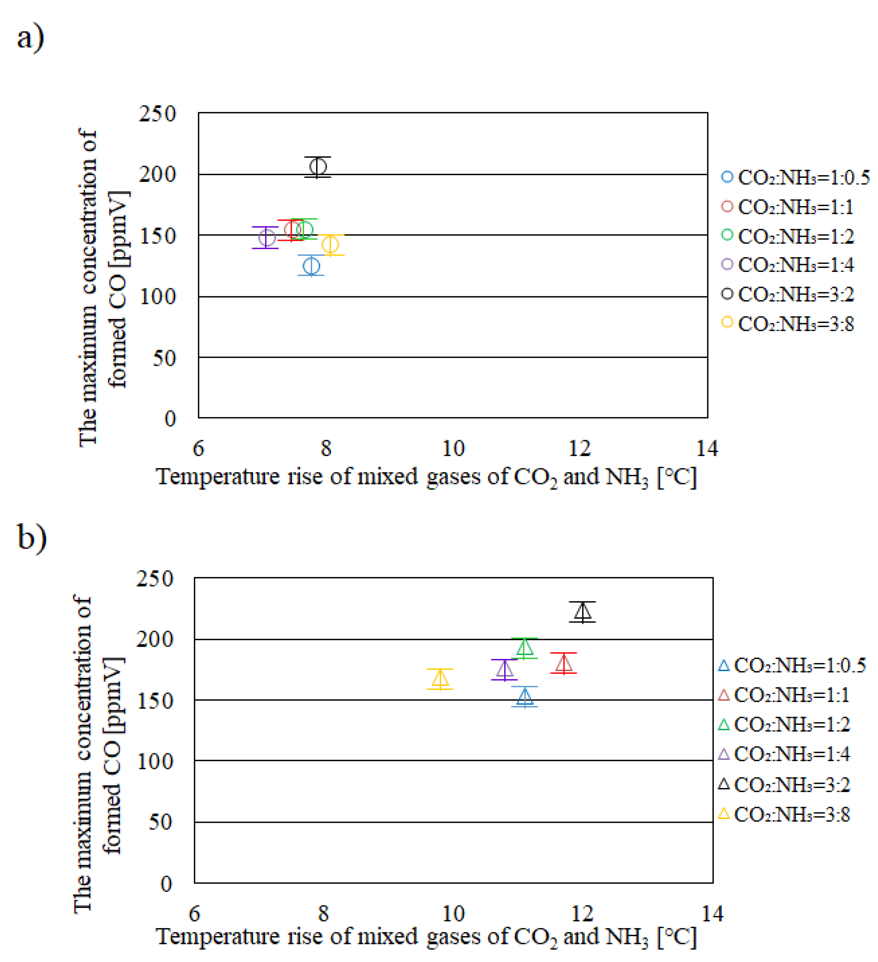
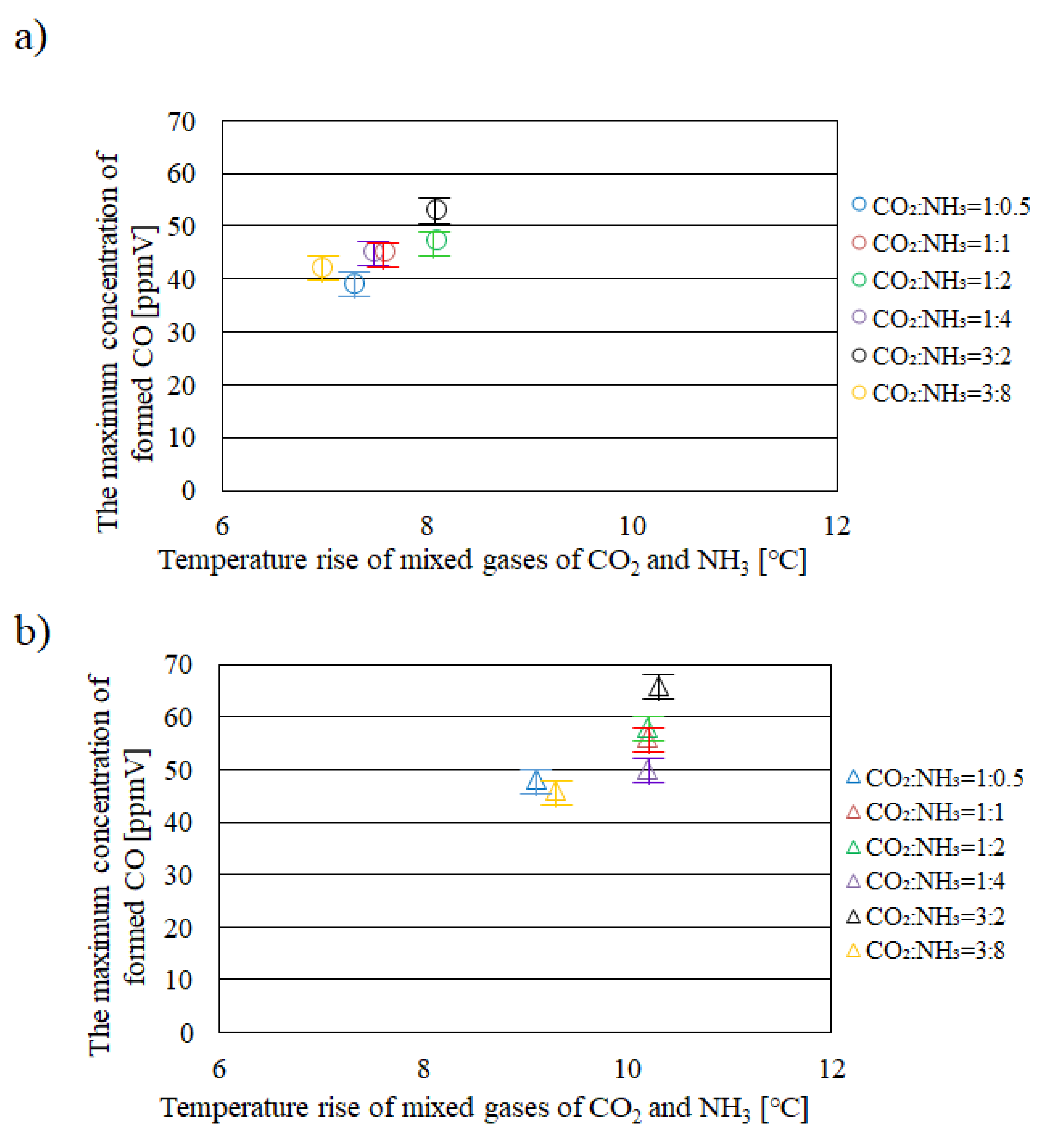
Figure 1, Figure 2 and Figure 3 show relationships between temperature rise of mixed gases of CO2 and NH3 in reactor and the maximum concentration of formed CO with and without black body material among different molar ratios of CO2/NH3 under the illumination conditions with UV + VIS + IR, VIS + IR and IR only, respectively [15]. In these figures, the temperature rise from the temperature at the start of CO2 reduction experiment to the temperature when the concentration of formed CO attains the maximum value [15] is shown.
It can be seen from Figure 1 that the temperature of mixed gases of CO2 and NH3 in reactor under the illumination condition with UV + VIS + IR rises by 3.8 °C – 6.2 °C due to black body materials, compared to that without black body material. According to this figure, the maximum concentration of formed CO increases by 21 ppmV – 71 ppmV due to black body materials, compared to that without black body material. It is seen from Figure 2 that the temperature of mixed gases of CO2 and NH3 in reactor under the illumination condition with VIS + IR rises by 1.0 °C – 2.9 °C due to black body materials, compared to that without black body material. According to this figure, the maximum concentration of formed CO increases by 19 ppmV – 40 ppmV due to black body materials, compared to that without black body material. It is seen from Figure 3 that the temperature of mixed gases of CO2 and NH3 in reactor under the illumination condition with IR only rises by 2.0 °C – 3.1 °C due to black body materials, compared to that without black body material. According to this figure, the maximum concentration of formed CO increases by 4 ppmV – 13 ppmV due to black body materials, compared to that without black body material. It is thought that the mass transfer surrounding the P4O10/TiO2 photocatalyst is promoted by the natural thermosiphon movement of gases around the P4O10/TiO2 photocatalyst created by black body materials irrespective of the illumination condition. This study would like to discuss and clarify the heat transfer mechanism to heat up the temperature of gases around P4O10/TiO2 photocatalyst due to black body material in the following section.

2.2. Heat Transfer Mechanism to Heat up Temperature of Mixed Gases of CO2 and NH3 around P4O10/TiO2 Photocatalyst due to Black Body Material

This study calculated the increased temperature of mixed gases of CO2 and NH3 (Tg) from the initial temperature (Tini) at the beginning of the CO2 reduction experiment. Table l lists the comparison of Tg with the temperature of mixed gases of CO2 and NH3 measured by thermocouple in the experiment (Te) in the authors’ previous study [15]. In this table, Tin, Tg, Te and TgTe among different molar ratios under the illumination conditions with UV + VIS + IR, VIS + IR and IR only are shown. This table indicates the effect of temperature rise due to black body material.
Table 1. Comparison of Tin (initial temperature of CO2 reduction experiment), Tg (increased temperature of mixed gases of CO2 and NH3), Te (temperature of mixed gases of CO2 and NH3 measured by thermocouple in the experiment) and TgTe among different molar ratios under the illumination condition with UV + VIS + IR, VIS + IR and IR only.
UV + VIS + IR
CO2 [mol] NH3 [mol] Tin [°C] Tg [°C] Te [°C] Tg – Te [°C]
1 0.5 24.7 36.7 46.5 9.8
1 1 24.0 36.5 44.9 8.4
1 2 24.1 36.8 45.2 8.4
1 4 24.2 36.9 45.2 8.3
3 2 24.1 36.4 45.9 9.5
3 8 24.4 37.1 45.2 8.1
VIS + IR
CO2 [mol] NH3 [mol] Tin [°C] Tg [°C] Te [°C] Tg – Te [°C]
1 0.5 25.4 36.3 36.8 0.5
1 1 25.0 36.3 36.7 0.4
1 2 24.5 36.0 35.6 -0.4
1 4 24.6 36.1 35.4 -0.7
3 2 24.3 35.4 35.5 0.1
3 8 24.4 35.9 34.2 -1.7
IR only
CO2 [mol] NH3 [mol] Tin [°C] Tg [°C] Te [°C] Tg – Te [°C]
1 0.5 25.3 34.2 34.8 0.6
1 1 24.6 33.8 34.8 1.0
1 2 24.6 33.9 34.9 1.0
1 4 24.4 33.7 35.6 1.9
3 2 24.7 33.7 35.0 1.3
3 8 25.0 34.3 34.3 0
It is seen from Table 1 that TgTe is nearly 0 under the illumination conditions with VIS + IR and IR only. Therefore, the heat transfer model proposed by this study predicts Tg well under the illumination conditions with VIS + IR and IR only. On the other hand, it is found from Table 1 that TgTe is larger under the illumination condition with UV + VIS + IR. This study assumes that the heat absorbed by black body material is converted from the illuminated light. In the heat transfer analysis, the heat absorbed by black body material is calculated by the light intensity measured using the light intensity meter. However, the heat converted from the light with each wave length is not calculated exactly. The emissive power of black body is a function of wavelength of light and is larger with the increase in the wavelength of light, especially within IR range [17]. Therefore, the heat absorbed by black body material under the illumination condition with UV + VIS + IR might be underestimated in this study. Table 2 lists Tg and TgTe calculated by the heat absorbed by black body materials which are 1.6 times or 1.7 times as large as that applied for Tg shown in Table 1 among different molar ratios under the illumination condition with UV + VIS + IR. According to Table 2, it is revealed that TgTe in case of the heat absorbed by black bod material, which is 1.6 times as large as that applied for Tg shown in Table 1, is ranged from 0.5 °C to 2.5 °C. In addition, TgTe in case of the heat absorbed by black bod material, which is 1.7 times as large as that applied for Tg shown in Table 1, is ranged from -0.8 °C to 1.3 °C. It is known from Table 2 that TgTe becomes smaller compared with that shown in Table 1, indicating that the prediction accuracy of the heat model proposed by this study would be improved. Therefore, this study would like to investigate the measurement procedure of light intensity following the light illumination condition and the heat conversion process for each wave length of light in the near future.
Table 2. Comparison of Tg and TgTe which are calculated by the heat absorbed by black bod materials which are 1.6 times or 1.7 times as large as that applied for Tg shown in Table 1 among different molar ratios under the illumination condition with UV + VIS + IR.
1.6 Q
CO2 [mol] NH3 [mol] Tg [°C] Tg – Te [°C]
1 0.5 44.0 2.5
1 1 44.1 0.8
1 2 44.4 0.8
1 4 44.5 0.7
3 2 43.8 2.1
3 8 44.7 0.5
1.7 Q
CO2 [mol] NH3 [mol] Tg [°C] Tg – Te [°C]
1 0.5 45.2 1.3
1 1 45.3 -0.4
1 2 45.7 -0.5
1 4 45.8 -0.6
3 2 450 0.9
3 8 46.0 -0.8
From the investigation of this study, it is confirmed that the mass transfer surrounding P4O10/TiO2 photocatalyst is promoted by the natural thermosiphon movement of gases around P4O10/TiO2 photocatalyst created by black body materials. The gases around P4O10/TiO2 photocatalyst are heated and the temperature of gases of product from the photocatalytic CO2 reduction increases, resulting that the gases would move upward. As a result, the fresh reacted gases of CO2 and NH3, which are blocked by the product from the photocatalytic CO2 reduction, i.e. CO, can reach the surface of photocatalyst. Since the photocatalytic reaction is a surface reaction, we can claim that this approach to improve the mass transfer is effective.

3. Experiments

3.1. Preparation Procedure of P4O10/TiO2 Film and Black Body Material

The P4O10/TiO2 film adopted in this study was prepared by sol-gel and dip-coating process as explained in the reference [15]. The P4O10/TiO2 film was coated on a netlike glass fiber (SILLIFGLASS U, manufacture: Nihonmuki Co., Tokyo, Japan) via sol-gel and dip-coating processes. The glass fiber having the diameter of about 10 m, which is weaved as a net, is assembled to be the diameter of about 1 mm. From the specification on netlike glass fiber, the porous diameter of glass fiber and the specific surface area are approximately 1 nm and 400 m2/g, respectively. The netlike glass fiber is composed of SiO2 of 96 wt%. The netlike glass fiber has the opening space of about 2 mm × 2 mm. Since the netlike glass fiber has a porous characteristic, the netlike glass fiber can trap the P4O10/TiO2 film easily via sol-gel and dip-coating processes. The netlike glass fiber is cut to be the disc form with the diameter of 50 mm and the thickness of 1 mm. The weight ratio of P4O10 to TiO2 was 2.0 wt%, which was confirmed by EPMA (Electron Probe Microanalyzer) analysis quantitatively [15].
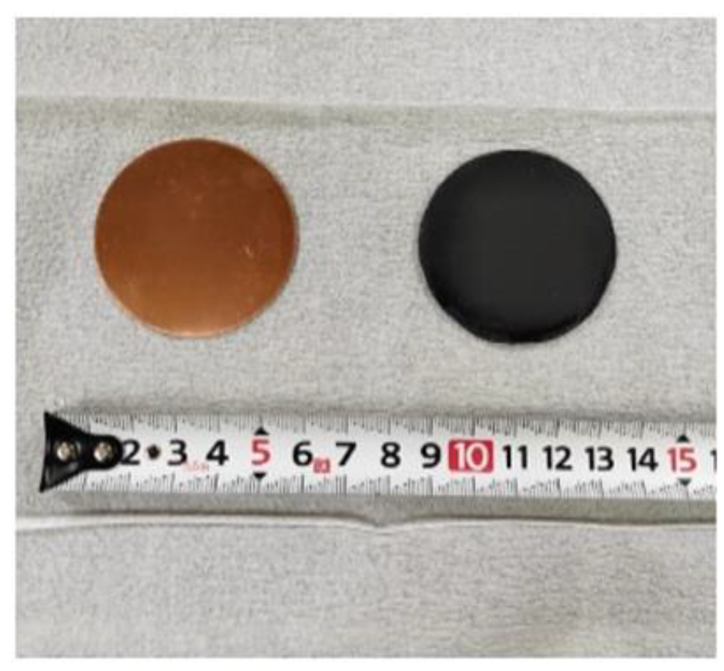
The black body material adopted by this study was prepared by spraying the black body spray (TA410KS, manufacture: ICHIKEN TASCO Corp., Osaka, Japan) on both surfaces of the Cu disc. The emissivity of black body spray was 0.94. This study adopted the Cu solid disc with the diameter of 50 mm and the thickness of 1.4 mm as a base material for spraying black body spray. The Cu solid disc had the diameter of 50 mm, which was equal to the inside diameter of the reactor. The emissivity of the polished Cu surface was 0.01 [18]. The used Cu solid disc had a purity of 99.90 % [19]. The specific heat, thermal conductivity, and thermal diffusivity of Cu at 30 °C were 0.386 kJ/(kg·K), 398 W/(m·K), and 117 mm2/s, respectively [18]. Three Cu solid discs, which were sprayed by the black body spray, were installed in the reactor in this study, referring the authors’ previous study [14]. According to the authors’ previous study [14], the promotion of CO2 reduction performance was not obtained by one Cu solid disc but three Cu solid discs. Figure 4 displays the black body material prepared by this study and the Cu solid disc before spraying black body spray [14,15].

3.2. The Experimental Procedure of CO2 Reduction and Temperature Measurement
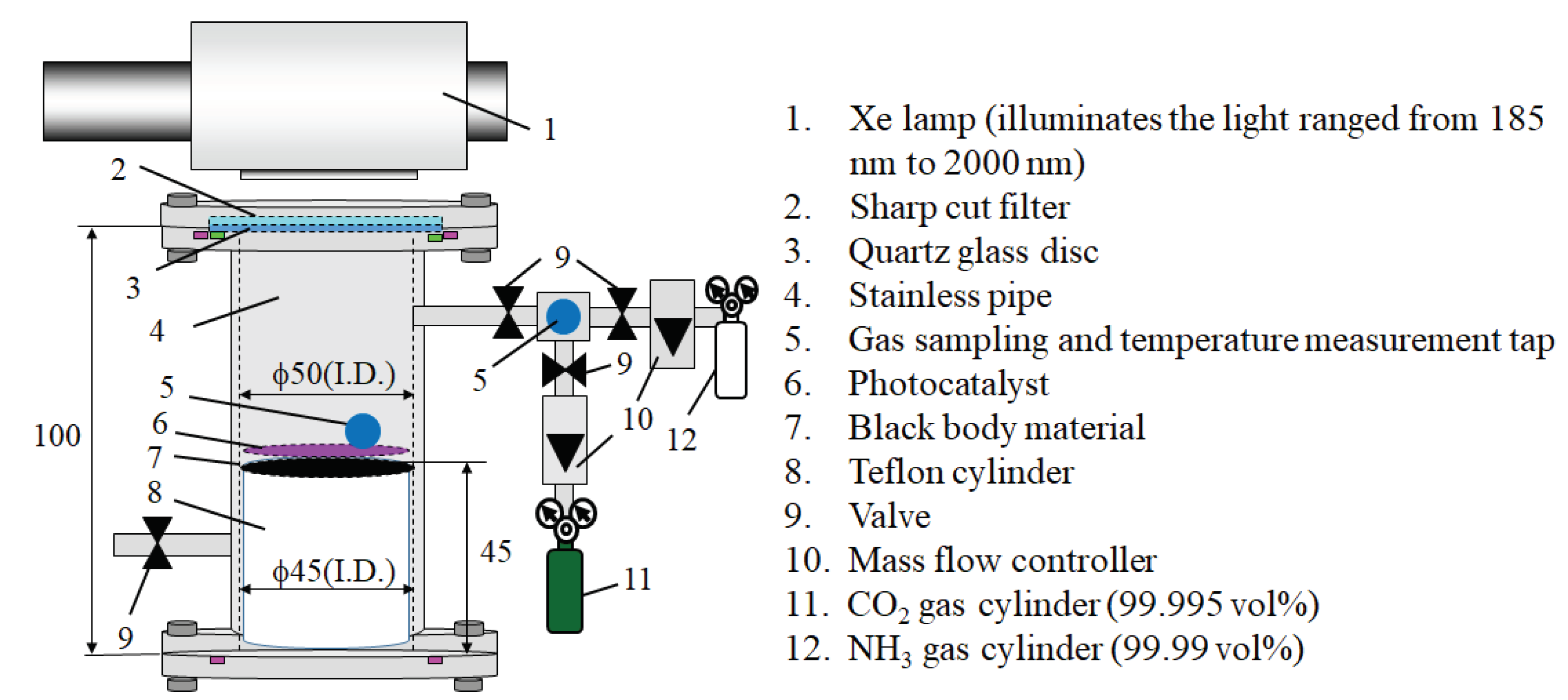
Figure 5 illustrates the experimental apparatus [15] applied for heat transfer analysis in this study. The reactor consists of a stainless tube having the scale of 100 mm (H.) × 50 mm (I.D.), P4O10/TiO2 film coated on the netlike glass disc having the scale of 50 mm (H.) × 50 mm (D.), a quartz glass disc having the scale of 84 mm (D.) × 10 mm (t.), a sharp cut filter removing the wavelength of light which is below 400 nm (SCF-49.5C-42L, manufacture: SIGMA KOKI CO LTD., Tokyo, Japan) or 800 nm (ITF-50C-85IR, manufacture: SIGMA KOKI CO LTD., Tokyo, Japan), a 150 W Xe lamp (L2175, manufacture: Hamamatsu Photonics K. K.), mass flow controller and CO2 gas cylinder (purity: 99.995 vol%) and NH3 gas cylinder (purity: 99.99 vol%). The reactor size for charging the gases was 1.25 × 10⁻⁴ m3. The three black body materials were located under the P4O10/TiO2 film coated on a netlike glass disc. The light of the Xe lamp positioned on the stainless tube was illuminated toward P4O10/TiO2 film. Since the netlike glass disc had the aperture area of the net, i.e. 4 mm2 for each, the illuminated light can reach the black body material. The light of Xe lamp located on the stainless tube was illuminated toward P4O10/TiO2 film passing the sharp cut filter and the quartz glass disc positioned on the top of the stainless tube. The wavelength of light illuminated from Xe lamp was distributed from 185 nm to 2000 nm. The sharp cut filter can remove UV and VIS from the Xe lamp, resulting that the wavelength of light illuminating on P4O10/TiO2 film was ranged from 401 nm to 2000 nm or 801 nm to 2000 nm [20]. The mean light intensity of light illuminated from Xe lamp from 185 nm to 2000 nm was 70.4 mW/cm2, that from 401 nm to 2000 nm was 60.7 mW/cm2, and that from 801 nm to 2000 nm was 46.6 mW/cm2, which were measured by light intensity meter (Nova ii; manufacture: OPHIR Japan).
After filling the CO2 gas with a purity of 99.995 vol% and NH3 with a purity of 99.99 vol%, they were controlled by a mass controller and introduced into the reactor pre-vacuumed by a vacuum pump for 15 min. The valves installed at the inlet and the outlet of the reactor were closed during CO2 reduction with NH3. After that, this study confirmed the pressure of 0.1 MPa and the gas temperature at 298 K in the reactor. Due to the heat of IR light components illuminated by the Xe lamp, the temperature of the gas in the reactor rose. The temperature of the experimental room was controlled and set at 293 K by an air conditioner. The molar ratio of CO2/NH3 was changed by 1:0.5, 1:1, 1:2, 1:4, 3:2, and 3:8. The reacted gas filled in the reactor was extracted by gas syringe via a gas sampling tap and it was analyzed by an FID gas chromatograph (GC353B, manufacture: GL Science) and a methanizer (MT221, manufacture: GL Science). The FID gas chromatograph and methanizer have a minimum resolution of 1 ppmV. The temperature of the gas in the reactor was measured by a B-type thermocouple installed in the tap, which was located 1 mm above the P4O10/TiO2 film coated on a netlike glass disc. The measurement error of the thermocouple is within 0.1 °C. The CO2 reduction experiment was conducted up to 8 hours. Gas sampling and temperature measurements were carried out from the start of the experiment until 8 hours by 2 hours. In this study, the maximum concentration of CO which in only produced from CO2 reduction and the maximum temperature rise obtained from the authors’ previous study [15] are used.
Figure 5. Schematic drawing of CO2 reduction experimental set-up applied for heat. transfer analysis in this study [15].
Preprints 88682 g005

4. Calculation Procedure for Heat Transfer Analysis

4.1. Heat Transfer Formulas

This study considers the heat transfer from P4O10/TiO2 photocatalyst which is coated on netlike glass disc fitted on the black body materials to the gases over P4O10/TiO2 photocatalyst. This study assumes that the illuminated light is converted into heat finally and absorbed by black body materials. Since the light intensity is different following the light illumination condition as described above, the converted heat which is absorbed by black body materials decreases in the order from UV +VIS + IR, VIS + IR to IR only. The temperature of mixed gases of CO2 and NH3, Tg, is calculated by the following formula:
Q = h A T g T i n i
where Q is a heat absorbed by black body materials [Q], h is a heat transfer coefficient [W/(m2·K)], A is a heat transfer area (= surface area of Cu disc on one side) [m2], Tini is an initial temperature of CO2 reduction experiment) [15] [K]. This study assumes that Tg is equal to the surface temperature of P4O10/TiO2 photocatalsyt and black body material. In other words, this study assumes that the mixed gases of CO2 and NH3 are heated up by P4O10/TiO2 photocatalsyt and black body material from Tini to Tg. h is calculated by the following formula:
h = N u λ d
where Nu is Nusselt number [–], is a thermal conductivity of the mixed gasses of CO2 and NH3 [W/(m·K)] and d is the representative length for each local Nu [m]. Nu is obtained from the following formula which can be applied for a laminar free convection heat transfer over a vertical flat plate [21].
N u x = 0.631 Pr 2 5 Pr + 0.9 Pr + 0.4 1 5 g β q x 4 ν 2 λ 1 5
where Pr is Prandtl number [-], g is a gravitational acceleration (= 9.81) [m2/s], is a volume expansion coefficient [1/K], q is a heat transfer rate (= Q/A), x is a position (= 5 mm interval up to Cu disc radius of 25 mm) [m], is a kinetic viscosity [m2/s]. The physical properties are calculated at the mean temperature of a quartz glass installed under the Xe lamp, which is 343 K, and the maximum temperature of mixed gases of CO2 and NH3 measured by thermocouple in the CO2 reduction experiment [15]. Under this condition, Pr for CO2 and NH3 are 0.766 and 0.95, respectively [21]. for CO2 and NH3 are 0.0097×10⁻⁶ m2/s and 0.51525×10⁻⁶ m2/s, respectively [22]. for CO2 and NH3 are 19.94×10⁻³ W/(m·K) and 42.95×10⁻³ W/(m·K), respectively [21]. for CO2 and NH3 are 3.722×10⁻⁶ 1/K and 3.790×10⁻⁶ 1/K, respectively. Each physical property under the different molar ratio conditions of CO2/NH3 is calculated based on the weight ratio of mixed gasses of CO2 and NH3. This study considers Q is converted from the illuminated light finally, which is calculated by the light intensity measured under each light illumination condition as described above, i.e. 1.08 W for UV + VIS + IR, 0.952 W for VIS + IR and 0.735 W for IR only. A is 1963×10-6 m2. According to these equations as shown above, Tg for each molar ratio of CO2/NH3 under each light illumination condition is obtained. In addition, Tg is compared with the maximum temperature measured by thermocouple in the CO2 reduction experiment in the authors’ previous study [15].

5. Conclusions

This study has developed a simple convective heat transfer model to calculate the temperature of mixed gases of CO2 and NH3 around P4O10/TiO2 photocatalyst and the black body material in the reactor, which was validated by experimental data in the authors’ previous study [15]. As a result, the following conclusions are drawn:
(i)
It is revealed that the heat transfer model proposed by this study can predict Tg well under the illumination condition with VIS + IR and IR only.
(ii)
It is revealed that TgTe is larger, e.g. 10 °C under the illumination condition with UV + VIS + IR compared with that under the illumination conditions with VIS + IR and IR only.
(iii)
TgTe under the illumination condition with UV + VIS + IR becomes smaller by increasing the heat absorbed by black bod materials by 1.6 times or 1.7 times as large as the case of calculation using the light intensity measured by the light intensity meter.
(iv)
The mass transfer surrounding P4O10/TiO2 photocatalyst is promoted by the natural thermosiphon movement of the gases around P4O10/TiO2 photocatalyst created by black body material according to the heat transfer analysis conducted in this study.

Author Contributions

Conceptualization and writing-original draft preparation, A.N.; data curation and formal analysis, R. H.; methodology, H.M. and S. H.; writing—review and editing, E.H. All authors have read and agreed to the published version of the manuscript.

Funding

This research was funded by Mie University and JSPS KAKENHI Grant Number JP21K04769.

Acknowledgments

The authors acknowledge JSPS KAKENHI Grant Number JP21K04769.

Conflicts of Interest

The authors declare no conflict of interest.

References

  1. Jesic, D.; Jurkovic, L. D.; Pohar, A.; Suhadolnik, L.; Likozar, B. Engineering Photocatalytic and Photoelectrocatalytic CO2 Reduction Reactions: Mechanisms, Intrinsic Kinetics, Mass Transfer Resistances, Reactors and Multi-scale Modeling Simulations. Chemical Engineering Journal 2021, 407. [Google Scholar] [CrossRef]
  2. Kaushik, R.; Singh P., K.; Halder, A. Modulation Strategies in Titania Photocatalyst for Energy Recovery and Environmental Remediation. Catalysis Today, 2022; 384-386, 45–69. [Google Scholar]
  3. Wang, Z. W.; Shi, Y. Z.; Liu, C.; Kang, Y. Y.; Wu, L. Cu+-Ti3+ Interface Interaction Mediated CO2 Coordination model for Controlling the Selectivity of Photocatalytic Reduction CO2. Applied Catalysis B: Environmental, 2022; 301. [Google Scholar] [CrossRef]
  4. Remiro-Buenamanana, S.; Garcia, H. Photoassisted CO2 Conversion into Fuels. Chem. Cat Chem. Minirev. 2019, 11, 342–356. [Google Scholar] [CrossRef]
  5. Cai, Y.; Luo, F.; Guo, Y.; Guo, F.; Shi, W.; Yang, S. Near-infrared Light Driven ZnIn2S4-based Photocatalysts for Environmental and Energy Applications: Progress and Perspectives. molecules 2023, 28. [Google Scholar] [CrossRef]
  6. Tahir, M. Synergistic Effect in MMT-dispersed Au/TiO2 Monolithic Nanocatalyst for Plasma-absorption and Metallic Interband Transitions Dynamic CO2 Photoreduction to CO. Appl. Catal. B Environ 2017, 219, 329–343. [Google Scholar] [CrossRef]
  7. Tahir, M.; Tahir, B.; Amin, N. A. S. Synergistic Effect in Plasmonic Au/Ag Alloy NPs Co-coated TiO2 NWs toward Visible-light Enhanced CO2 Photoreduction to Fuels. Appl. Catal. B Enviorn 2017, 204, 548–560. [Google Scholar] [CrossRef]
  8. Hong, L. F.; Guo, R. T.; Yuan, Y.; Ji, X. Y.; Lin, Z. D.; Gu, J. W.; Pan, W. G. Urchinlike W18O49/g-C3N4 Z-Scheme Heterojunction for Highly Efficient Photocatalytic Reduction of CO2 under Full Spectrum Light. Energy Fuels 2021, 35, 11468–11478. [Google Scholar] [CrossRef]
  9. Dai, W.; Yu, J.; Luo, S.; Hu, X.; Yang, L.; Zhang, S.; Li, B.; Luo, X.; Zou, J. WS2 Quantum Dots Seeding in Bi2S3 Nanotubes: A Novel Vis-NIR Light Sensitive Photocatalyst with Low-Resistance Junction Interface for CO2 Reduction. Chemical Engineering Journal 2020, 389. [Google Scholar] [CrossRef]
  10. Gan, J.; Wang, H.; Hu, H.; Su, M.; Chen, F.; Xu, H. Efficient Synthesis of Tunable Band-Gap CuInZnS Decorated g-C3N4 Hybrids for Enhanced CO2 Photocatalytic Reduction and Near-Infrared- Triggered Photordegradation Performance. Applied Surface Science 2021, 564. [Google Scholar] [CrossRef]
  11. Yu, M.; Lv, X.; Idris, A. M.; Li, S.; Lin, J.; Lin, H.; Wang, J.; Li, Z. Upconversion Nanoparticles Coupled with Hierarchical ZnIn2S4 Nanorods as a Near-Infrared Responsive Photocatalyst for Photocatalytic CO2 Reduction. Journal of Colloid and Interface Science 2022, 612, 782–791. [Google Scholar] [CrossRef] [PubMed]
  12. Nishimura, A.; Mae, H.; Kato, T.; Hu, E. Utilization from ultraviolet to infrared light for CO2 reduction with P4O10/TiO2 photocatalyst. Physics & Astronomy International Journal, 2022; 6, 145–154. [Google Scholar]
  13. Nishimura, A.; Mae, H.; Hannyu, R.; Hu, E. Impact of loading amount of P4O10 on CO2 reduction performance of P4O10/TiO2 with H2O extending absorption range from ultraviolet to infrared light. Physics & Astronomy International Journal, 2022; 6, 186–194. [Google Scholar]
  14. Nishimura, A.; Kato, T.; Mae, H.; Hu, E. Impact of black body material enhanced gas movement on CO2 photocatalytic reduction performance. catalysts 2022, 12. [Google Scholar] [CrossRef]
  15. Nishimura, A.; Hanyu, R.; Mae, H.; Hu, E. Impact of Black Body Material on CO2 Reduction Performance of P4O10/TiO2 with NH3. Journal of Physics and Chemistry Research 2023, 5. [Google Scholar]
  16. Nishimura, A.; Komatsu, N.; Mitsui, G.; Hirota, M.; Hu, E. CO2 Reforming into Fuel Using TiO2 Photocatalyst and Gas Separation Membrane. Catalysis Today 2009, 148, 341–349. [Google Scholar] [CrossRef]
  17. Holman, J. P. Heat Transfer, 8th ed.; McGRAW-HILL, INC.: New York, USA, 1997; p. 400. [Google Scholar]
  18. Japan Society of Mechanical Engineering. Heat Transfer Hand Book, 1st ed.; Maruzen: Tokyo, Japan, 1993; p. 238, 367-369. [Google Scholar]
  19. Tahir, M.; Amin, N.S. Photocatalytic Reduction of Carbon Dioxide with Water Vapors over Montmorillonite Modified TiO2 Nanocomposites. Appl. Catal. B. Environ. 2013; 142-143, 512–522. [Google Scholar]
  20. Nishimura, A.; Mitsui, G.; Nakamura, K.; Hirota, M.; Hu, E. CO2 reforming characteristics under visible light response of Cr- or Ag-doped TiO2 prepared by sol-gel and dip-coating process. Int. J. Photoenergy. 2012, Article ID 184169,. [CrossRef]
  21. Aihara, T. Heat Transfer Engineering, 1st ed.; Syokabo: Tokyo, Japan, 1994; p. 107, 274. [Google Scholar]
  22. Hasatani, M.; Kimura, J. Basis and Application for Combustion, 2nd ed.; Kyoritsu Shuppan: Tokyo, Japan, 1986; p. 276. [Google Scholar]
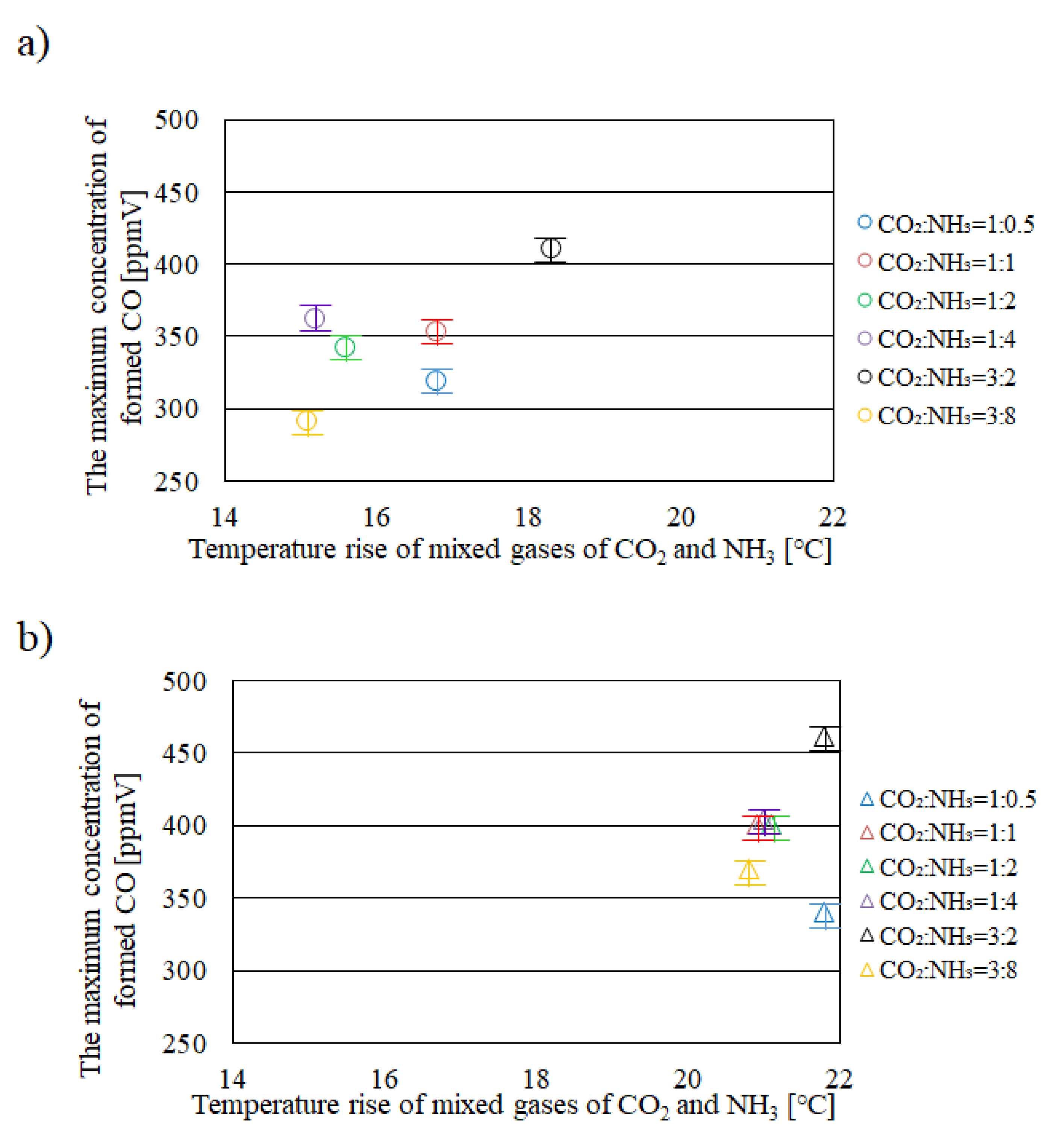
Figure 1. Relationships between temperature rise of mixed gases of CO2 and NH3 in reactor and the maximum concentration of formed CO among different molar ratios of CO2/NH3 under the illumination condition with UV + VIS + IR (a): without black body material, b): with black body materials) [15].
Preprints 88682 g001
Figure 2. Relationships between temperature rise of mixed gases of CO2 and NH3 in reactor and the maximum concentration of formed CO among different molar ratios of CO2/NH3 under the illumination condition with VIS + IR (a): without black body material, b): with black body materials) [15].
Preprints 88682 g002
Figure 3. Relationships between temperature rise of mixed gases of CO2 and NH3 in reactor and the maximum concentration of formed CO among different molar ratios of CO2/NH3 under the illumination condition with IR only (a): without black body material, b): with black body materials) [15].
Preprints 88682 g003
Figure 4. Photo of black body material adopted for the heat transfer analysis and Cu solid disc before splaying black body spray [14,15].
Preprints 88682 g004
Disclaimer/Publisher’s Note: The statements, opinions and data contained in all publications are solely those of the individual author(s) and contributor(s) and not of MDPI and/or the editor(s). MDPI and/or the editor(s) disclaim responsibility for any injury to people or property resulting from any ideas, methods, instructions or products referred to in the content.
Copyright: This open access article is published under a Creative Commons CC BY 4.0 license, which permit the free download, distribution, and reuse, provided that the author and preprint are cited in any reuse.
Prerpints.org logo

Preprints.org is a free preprint server supported by MDPI in Basel, Switzerland.

Subscribe

© 2024 MDPI (Basel, Switzerland) unless otherwise stated