Preprint
Article

Magnetic Fields and Asymptotic Limits of Current Loops

Altmetrics

Downloads

132

Views

50

Comments

0

This version is not peer-reviewed

Submitted:

25 January 2024

Posted:

26 January 2024

You are already at the latest version

Alerts
Abstract
This article theoretically derives the magnetic field and vector potential produced by a steady current I flowing in an arbitrary plane loop at an arbitrary point r. Numerical examples are presented to demonstrate the behavior of the magnetic field produced by loops of various shapes such as polygons, circles, ellipses, and p-norm balls. Taking the limit as the loop shrinks to a point and the current I grows to infinity so that the magnetic dipole moment m of the loop (defined as the current I times the vector area of the loop) is kept constant, the magnetic field and vector potential are theoretically shown to converge to those of an ideal point magnetic dipole m.
Keywords: 
Subject: Physical Sciences  -   Theoretical Physics

1. Introduction

Ever since the Danish physicist Hans Christian Ørsted discovered [1] that a current carrying wire deflects a magnetic needle kept in its vicinity, philosophers and natural scientists have researched [2] on the connection between magnetic fields as observed near bar magnets and lodestones [3,5], and electric currents. Laplace, Biot, Savart, Ampère, and others experimentally observed [7] that the magnetic field B ( r ) produced by a steady current density J ( r ) distributed over a set r D is given by
B ( r ) = μ 0 4 π D J × ( r r ) r r 3 d V .
This result, commonly known as the Biot–Savart law, was used by Maxwell to formulate the so-called Ampère’s circuital law [8,9], which states that the circulation of the magnetic field B produced by a steady (time-invariant) current over a closed loop is proportional to the total current flowing through the surface, or, equivalently in differential form, × B = μ 0 J , where J is the volume current density and × A for a vector field A ( r ) A x ( r ) x ^ + A y ( r ) y ^ + A z ( r ) z ^ is defined as
× A : = A z y A y z x ^ + A x z A z x y ^ + A y x A x y z ^ .
With Maxwell’s unification of electromagnetism [10], Ampère’s circuital law was incorporated as part of Maxwell’s equations [4,11,12]. Maxwell’s work also comprehensively laid out the exact connections between sources and fields, as well as electric and magnetic fields [14]. Further unification was achieved with the advent of special relativity [15,16], when it was shown that electric and magnetic fields are in fact components of a rank-2 tensor field, the electromagnetic field [18], through the work of Einstein [16], Lorentz [19], Poincaré [20], and others. During this period, several experiments designed to test various hypotheses around the so-called luminiferous ether [21] also failed and thereby experimentally confirmed the validity of this unification [22,23]. One of the most notable of these experiments was that conducted by Michelson and Morley in 1887 [24,25]. The Michelson–Morley experiment aimed to measure the velocity of the earth relative to the luminiferous ether and involved some of the most precise measurements ever made in physics till then. A state of the art interferometer [26] was used for the measurement, and this remarkably well-designed experiment further contributed in retrospect to the demise of the ether theory [27].
The rest of the paper is organized as follows. Section 2.1 presents the magnetic field and vector potential produced at an arbitrary point by a steady current flowing in a circular loop of finite radius a .  Section 2.2 generalizes this result to an arbitrary closed loop [8] on a plane and numerically examines the behavior of the magnetic fields produced by loops of various shapes. Section 3.1 theoretically establishes that the magnetic field and vector potential [6,13] due to a circular current loop approach that of an ideal magnetic dipole as the loop shrinks to a point while keeping the magnetic moment fixed, and Section 3.2 generalizes the convergence result to an arbitrary closed and differentiable loop on a plane. Section 4 concludes the paper.

2. Field of a loop current

In this section, we use the Biot–Savart law (1) to derive the magnetic field B produced by a plane current loop carrying a steady current I . Without loss of generality, we can take the current loop to be in the x y -plane.

2.1. Circular current loop

We first consider the case of a circular loop of radius a , centered at the origin. With our choice of coordinates, the current distribution has azimuthal symmetry, i.e., for any coordinate transformation ϕ ϕ + c for any constant c R , the form of the current distribution remains unchanged. This implies that the magnetic field at any point r will be independent of ϕ and will not have any component along the ϕ ^ direction. We can therefore take the point r to be on the z x -plane without loss of generality. The differential magnetic field produced at this point r = x x ^ + z z ^ by a differential element d l = a d ϕ of the current loop located at r = a cos ϕ x ^ + a sin ϕ y ^ is given, using (1), by
d B = μ 0 a I 4 π ϕ ^ r × r a cos ϕ x ^ a sin ϕ y ^ r a cos ϕ x ^ a sin ϕ y ^ 3 d ϕ = μ 0 a I 4 π ( sin ϕ x ^ + cos ϕ y ^ ) × ( x a cos ϕ ) x ^ a sin ϕ y ^ + z z ^ ( x a cos ϕ ) x ^ a sin ϕ y ^ + z z ^ 3 d ϕ = μ 0 a I 4 π z cos ϕ x ^ + z sin ϕ y ^ + ( a x cos ϕ ) z ^ x 2 + z 2 + a 2 2 a x cos ϕ 3 / 2 d ϕ .
We can integrate (2) to obtain the magnetic field B at the point r . As mentioned earlier, due to the azimuthal symmetry of the problem [17], the ϕ component (or since r is chosen to be in the z x -plane, the y component) of B should be zero. We arrive at the same conclusion from (2) by seeing that
B y = μ 0 a z I 4 π 0 2 π sin ϕ x 2 + z 2 + a 2 2 a x cos ϕ 3 / 2 d ϕ = ( a ) μ 0 a z I 4 π π π sin ϕ x 2 + z 2 + a 2 2 a x cos ϕ 3 / 2 d ϕ = ( b ) 0 ,
where ( a ) follows since trigonometric functions are periodic with period 2 π , and ( b ) follows since the integrand is odd. We can write the x component of B as
B x = μ 0 a z I 4 π 0 2 π cos ϕ x 2 + z 2 + a 2 2 a x cos ϕ 3 / 2 d ϕ = μ 0 a z I 4 π π π cos ϕ x 2 + z 2 + a 2 2 a x cos ϕ 3 / 2 d ϕ = ( a ) 2 μ 0 a z I 4 π 0 π cos ϕ x 2 + z 2 + a 2 2 a x cos ϕ 3 / 2 d ϕ = 2 μ 0 a z I 4 π x 2 + z 2 + a 2 3 / 2 0 π cos ϕ 1 2 a x x 2 + z 2 + a 2 cos ϕ 3 / 2 d ϕ = ( b ) μ 0 z m 4 π x 2 + z 2 + a 2 3 / 2 · 2 π a 0 π cos ϕ 1 2 a x x 2 + z 2 + a 2 cos ϕ 3 / 2 d ϕ = μ 0 z m 4 π x 2 + z 2 + a 2 3 / 2 · 2 π a f ( 1 ) 2 a x / ( x 2 + z 2 + a 2 ) ,
where
f ( 1 ) ( t ) : = 0 π cos ϕ 1 t cos ϕ 3 / 2 d ϕ .
Here, ( a ) follows since the integrand in the previous step is an even function, and in ( b ) ,  m is the magnetic dipole moment π a 2 I . Following similar steps, we can integrate the z component of (2) to write
B z = μ 0 m 4 π x 2 + z 2 + a 2 3 / 2 · 2 π f ( 2 ) 2 a x / ( x 2 + z 2 + a 2 ) x a f ( 1 ) 2 a x / ( x 2 + z 2 + a 2 ) ,
where
f ( 2 ) ( t ) : = 0 π 1 1 t cos ϕ 3 / 2 d ϕ .
Using (3) and (4) and taking t : = 2 a x / ( x 2 + z 2 + a 2 ) , we can write the magnetic field B ( r ) as
B ( r ) = μ 0 m 4 π x 2 + z 2 + a 2 3 / 2 · 2 π z a f ( 1 ) ( t ) x ^ + f ( 2 ) ( t ) x a f ( 1 ) ( t ) z ^ .
Converting to spherical polar coordinates with x 2 + z 2 = r 2 ,   z = r cos θ ,   x = r sin θ ,   x ^ = sin θ r ^ + cos θ θ ^ , and z ^ = cos θ r ^ sin θ θ ^ , (5) becomes
B ( r ) = μ 0 m 4 π r 2 + a 2 3 / 2 · 2 π f ( 2 ) ( t ) cos θ r ^ + r f ( 1 ) ( t ) a f ( 2 ) ( t ) sin θ θ ^ .
We thus have the following lemma.
Lemma 1. 
The magnetic field B at a point r (with spherical polar coordinates ( r , θ , ϕ ) ) produced by a circular loop of radius a and magnetic moment m placed on the x y -plane with its center at the origin, is given by
B ( r ) = μ 0 m 4 π r 2 + a 2 3 / 2 · 2 π f ( 2 ) ( t ) cos θ r ^ + r f ( 1 ) ( t ) a f ( 2 ) ( t ) sin θ θ ^ ,
where
f ( 1 ) ( t ) : = 0 π cos ϕ 1 t cos ϕ 3 / 2 d ϕ ,
f ( 2 ) ( t ) : = 0 π 1 1 t cos ϕ 3 / 2 d ϕ , and
t : = 2 a r sin θ r 2 + a 2 .
Remark 1. 
The integrals in eqns (7) and (8) are referred to as elliptic integrals [28]. They have no finite closed form expressions in terms of elementary functions.
Figure 1 illustrates the magnetic field lines on a vertical plane (i.e., containing the z axis) obtained in accordance with Lemma 1. The red line segment represents the diameter of the current loop. The field lines form closed loops and all of them cross the current loop.
Remark 2. 
When the field point r is on the x y -plane (i.e., θ = π / 2 ), (6) yields
B = μ 0 4 π r 2 + a 2 3 / 2 · 2 π f ( 2 ) 2 a r r 2 + a 2 r a f ( 1 ) 2 a r r 2 + a 2 m ,
which shows that the field on the plane of the loop is always perpendicular to the plane, as one can expect from the form of the Biot–Savart law [39].
Remark 3. 
Lemma 1 has a specialization which is commonly derived in freshman physics classes. For a point r on the z axis (i.e., θ = 0 ), eqn (6) yields
B ( r ) = μ 0 m 4 π r 2 + a 2 3 / 2 · 2 π f ( 2 ) ( 0 ) r ^ + r f ( 1 ) ( 0 ) a θ ^ = μ 0 4 π 2 m r 2 + a 2 3 / 2 .
We can also establish the magnetic vector potential for the current loop, as presented in the following lemma.
Lemma 2. 
The magnetic vector potential A at a point r (with spherical polar coordinates ( r , θ , ϕ ) ) produced by a circular loop of radius a and magnetic moment m placed on the x y plane with its center at the origin, is given by
A ( r ) = μ 0 4 π r 2 + a 2 1 / 2 · 2 π a sin θ f ( 3 ) 2 a r sin θ r 2 + a 2 m × r ^ ,
where
f ( 3 ) ( t ) : = 0 π cos ϕ 1 t cos ϕ 1 / 2 d ϕ .
Proof. 
The magnetic vector potential A ( r ) produced by a steady current density J ( r ) distributed over a set r D can be written as (see, for example, [33])
A ( r ) = μ 0 4 π D J r r d V .
Similar to (2), the differential vector potential at a point r = x x ^ + z z ^ by a differential element d l = a d ϕ of the current loop located at r = a cos ϕ x ^ + a sin ϕ y ^ is given, using (13), by
d A = μ 0 a I 4 π 1 r a cos ϕ x ^ a sin ϕ y ^ d ϕ ϕ ^ = μ 0 a I 4 π sin ϕ x ^ + cos ϕ y ^ x 2 + z 2 + a 2 2 a x cos ϕ 1 / 2 d ϕ .
We can integrate (14) to calculate the vector potential A . We have
A x = μ 0 a I 4 π 0 2 π sin ϕ x 2 + z 2 + a 2 2 a x cos ϕ 1 / 2 d ϕ = ( a ) μ 0 a I 4 π π π sin ϕ x 2 + z 2 + a 2 2 a x cos ϕ 1 / 2 d ϕ = ( b ) 0 ,
where ( a ) follows since trigonometric functions are periodic with period 2 π , and ( b ) follows since the integrand in the previous step is an odd function. We similarly have
A y = μ 0 a I 4 π 0 2 π cos ϕ x 2 + z 2 + a 2 2 a x cos ϕ 1 / 2 d ϕ = ( a ) μ 0 a I 4 π π π cos ϕ x 2 + z 2 + a 2 2 a x cos ϕ 1 / 2 d ϕ = ( b ) 2 μ 0 a I 4 π 0 π cos ϕ x 2 + z 2 + a 2 2 a x cos ϕ 1 / 2 d ϕ = 2 μ 0 a I 4 π x 2 + z 2 + a 2 1 / 2 0 π cos ϕ 1 2 a x x 2 + z 2 + a 2 cos ϕ 1 / 2 d ϕ = μ 0 m 4 π x 2 + z 2 + a 2 1 / 2 · 2 π a f ( 3 ) 2 a x x 2 + z 2 + a 2 ,
where f ( 3 ) ( · ) is as defined in (12). Here, ( a ) follows since trigonometric functions are periodic with period 2 π , and ( b ) follows since the integrand in the previous step is an even function [42].Converting to spherical polar coordinates with x 2 + z 2 = r 2 ,   x = r sin θ , and y ^ = ϕ ^ , (15) becomes
A ( r ) = μ 0 m 4 π r 2 + a 2 1 / 2 · 2 π a f ( 3 ) 2 a r sin θ r 2 + a 2 ϕ ^ = ( a ) μ 0 m 4 π r 2 + a 2 1 / 2 · 2 π a sin θ f ( 3 ) 2 a r sin θ r 2 + a 2 z ^ × r ^ = μ 0 4 π r 2 + a 2 1 / 2 · 2 π a sin θ f ( 3 ) 2 a r sin θ r 2 + a 2 m × r ^ .
This establishes the result. Here, ( a ) follows from the observation that
ϕ ^ = r ^ × θ ^ = 1 sin θ r ^ × cos θ r ^ sin θ θ ^ = 1 sin θ z ^ × r ^ .
In the following subsection, we generalize Lemmas 1 and 2 to general planar loops.

2.2. General current loop on a plane

Consider a current loop on the x y -plane described in polar coordinates ( ρ , ϕ ) as ρ = λ · γ ϕ / 2 π , where γ : [ 0 , 1 ] R + is continuously differentiable almost everywhere in [ 0 , 1 ] , bounded below (i.e., inf u [ 0 , 1 ] γ ( u ) > 0 ), satisfies γ ( 0 ) = γ ( 1 ) , and
0 1 γ ( u ) 2 d u = 1 π .
Eqn (16) defines the scale of the loop, since the area enclosed by the loop is given by
1 2 0 2 π r 2 d ϕ = λ 2 2 0 2 π γ ϕ / 2 π 2 d ϕ = λ 2 .
Thus, L ( λ ; γ ) : = { ( x , y ) : x = λ γ ( u ) cos ( 2 π u ) , y = λ γ ( u ) sin ( 2 π u ) , u [ 0 , 1 ] } defines a family of “similar” loops parametrized by λ , where the area enclosed by L ( λ ; γ ) is given by λ 2 . Henceforth, we refer to “the loop L ( λ ; γ ) ” to refer to a loop in the shape given by L ( λ ; γ ) . The following lemma establishes the magnetic field and vector potential produced by a uniform steady current I flowing in the loop L ( λ ; γ ) .
Lemma 3. 
The magnetic vector potential A at a point r (with spherical polar coordinates ( r , θ , ϕ ) ) produced by a loop L ( λ ; γ ) with magnetic moment m = m z ^ placed on the x y -plane is given by
A ( r , λ ; γ ) = μ 0 4 π λ m × ( r ^ sin θ + θ ^ cos θ 0 1 2 π γ ( u ) cos ( 2 π u ϕ ) + γ ( u ) sin ( 2 π u ϕ ) λ 2 γ ( u ) 2 2 λ r γ ( u ) sin θ cos ( 2 π u ϕ ) + r 2 1 / 2 d u + ϕ ^ 0 1 2 π γ ( u ) sin ( 2 π u ϕ ) γ ( u ) cos ( 2 π u ϕ ) λ 2 γ ( u ) 2 2 λ r γ ( u ) sin θ cos ( 2 π u ϕ ) + r 2 1 / 2 d u ) .
The magnetic field at the point r is given by
B ( r , λ ; γ ) = μ 0 m 4 π λ ( 2 π λ cos θ r ^ 0 1 γ ( u ) 2 λ 2 γ ( u ) 2 2 λ r γ ( u ) sin θ cos ( 2 π u ϕ ) + r 2 3 / 2 d u + θ ^ 0 1 2 π r γ ( u ) cos ( 2 π u ϕ ) + r γ ( u ) sin ( 2 π u ϕ ) 2 π λ sin θ γ ( u ) 2 λ 2 γ ( u ) 2 2 λ r γ ( u ) sin θ cos ( 2 π u ϕ ) + r 2 3 / 2 d u + r cos θ ϕ ^ 0 1 2 π γ ( u ) sin ( 2 π u ϕ ) γ ( u ) cos ( 2 π u ϕ ) λ 2 γ ( u ) 2 2 λ r γ ( u ) sin θ cos ( 2 π u ϕ ) + r 2 3 / 2 d u ) .
The proof of Lemma 3 follows immediately from the Biot–Savart Law (1) and the vector potential expression (13) very similarly to the proofs of Lemmas 1 and 2, and is omitted.
Remark 4. 
One can easily see that Lemma 3 recovers the results of Lemmas 1 and 2 by setting γ 1 / π and λ = a · π .
Remark 5. 
Similarly to Remark 3, Lemma 3 can be specialized to the case θ = 0 (i.e., the field at a point on the z-axis) to obtain
B ( r , λ ; γ ) = μ 0 m 2 0 1 γ ( u ) 2 λ 2 γ ( u ) 2 + r 2 3 / 2 d u + μ 0 m 4 π λ ( x ^ 0 1 2 π r γ ( u ) cos ( 2 π u ) + r γ ( u ) sin ( 2 π u ) λ 2 γ ( u ) 2 + r 2 3 / 2 d u + y ^ 0 1 2 π r γ ( u ) sin ( 2 π u ) r γ ( u ) cos ( 2 π u ) λ 2 γ ( u ) 2 + r 2 3 / 2 d u ) .
Remark 6. 
For a point r on the x y -plane, similarly to Remark 2, Lemma 3 reduces to
B ( r , λ ; γ ) = μ 0 m 4 π λ 0 1 2 π λ γ ( u ) 2 2 π r γ ( u ) cos ( 2 π u ϕ ) r γ ( u ) sin ( 2 π u ϕ ) λ 2 γ ( u ) 2 2 λ r γ ( u ) cos ( 2 π u ϕ ) + r 2 3 / 2 d u .
We now study some examples of commonly encountered families of loops L ( λ ; γ ) and examine the magnetic fields and vector potentials produced by steady currents flowing in such loops.
Example 1 
(Polygon). A polygonal loop with N vertices may be defined in terms of the vertex coordinates { ( r i , ϕ i ) , i = 1 , , N } , where 0 ϕ i < 2 π for each i , and the coordinates are sorted such that ϕ 1 < ϕ 2 < < ϕ N , as
γ ( N ) ( u ) = 2 j = 1 N r j r j + 1 sin ϕ j + 1 ϕ j 1 / 2 · r i r i + 1 sin ϕ i + 1 ϕ i r i sin 2 π u ϕ i + r i + 1 sin ϕ i + 1 2 π u , u ϕ i 2 π , ϕ i + 1 2 π
for i = 1 , 2 , , N , where we choose the convention ϕ N + 1 ϕ 1 . As a special case, if r i = a / 2 sin π / N for each i and ϕ i = i 1 / 2 2 π / N for i = 1 , 2 , , N , the polygon becomes regular and (21) reduces to
γ reg . ( N ) ( u ) = 2 sin π N 2 a 2 N sin 2 π / N 1 / 2 × a 2 sin π / N × sin 2 π / N sin 2 π u i 1 / 2 2 π / N + sin i + 1 / 2 2 π / N 2 π u = 1 N tan π / N 1 / 2 · 1 cos 2 π u i / N
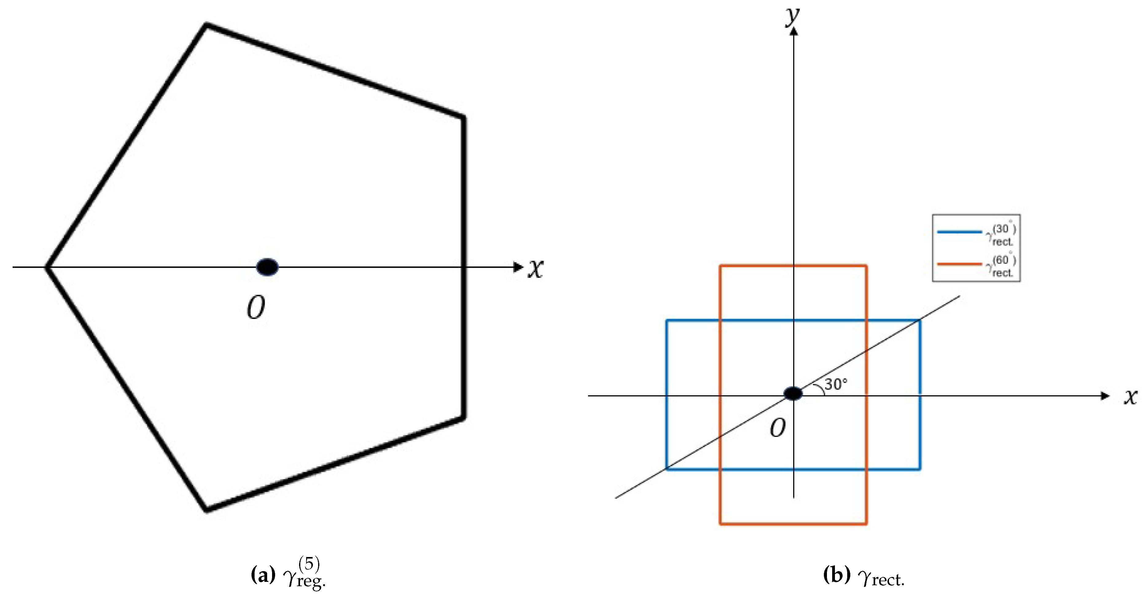
for u i 1 / 2 N , i + 1 / 2 N mod 1 ,   i = 1 , 2 , , N .  Figure 2a geometrically depicts γ reg . ( N ) for N = 5 (i.e., a regular pentagon). A common special case of (22) can be obtained by setting N = 4 (i.e., a square). We have
γ reg . ( 4 ) ( u ) = 1 2 cos 2 π u i π / 2 = 1 2 sin ( 2 π u ) , u [ 1 / 8 , 3 / 8 ] , 1 2 cos ( 2 π u ) , u [ 3 / 8 , 5 / 8 ] , 1 2 sin ( 2 π u ) , u [ 5 / 8 , 7 / 8 ] , 1 2 cos ( 2 π u ) , u [ 7 / 8 , 1 ] [ 0 , 1 / 8 ] .
A different special case of (21) can be obtained by setting N = 4 ,   ϕ 1 = α ,   ϕ 2 = π α ,   ϕ 3 = π + α ,   ϕ 4 = 2 π α , and r 1 = r 2 = r 3 = r 4 = a > 0 , for some α ( 0 , π / 2 ) . The reader may recognize this loop as a rectangle, with α = π / 4 corresponding to the square (23). We then have
γ rect . ( α ) ( u ) = tan α 1 / 2 2 1 sin ( 2 π u ) , u α 2 π , 1 2 α 2 π , 1 2 tan α 1 / 2 1 cos ( 2 π u ) , u 1 2 α 2 π , 1 2 + α 2 π , tan α 1 / 2 2 1 sin ( 2 π u ) , u 1 2 + α 2 π , 1 α 2 π , 1 2 tan α 1 / 2 1 cos ( 2 π u ) , u 1 α 2 π , 1 0 , α 2 π .
One can verify that both the square (23) and the rectangle (24) have unit area, by noting that the square has side length 1 , while the rectangle has side lengths tan α 1 / 2 and 1 / tan α 1 / 2 .  Figure 2b geometrically depicts γ rect . ( α ) for α = π / 6 and π / 3 .
Example 2 
(Ellipse). An elliptical loop with eccentricity ϵ and major axis of length 2 a with one focus at the origin and another focus at ( r , ϕ ) = ( 2 a ϵ , 0 ) , may be defined as the locus of a point which moves such that the distances of the point from the two foci sums to 2 a . When ϵ = 0 , the two foci coincide and the ellipse reduces to a circle of radius a . We have, for any point ( r , ϕ ) on the ellipse,
r + r 2 + 2 a ϵ 2 4 r a ϵ cos ϕ = 2 a r 2 + 2 a ϵ 2 4 r a ϵ cos ϕ = ( 2 a r ) 2 4 r a ( 1 ϵ cos ϕ ) = 4 a 2 ( 1 ϵ 2 ) r = a 1 ϵ 2 1 ϵ cos ϕ .
We therefore have
γ ellipse ( ϵ ) ( u ) = K 1 ϵ cos ( 2 π u ) ,
where K is a constant to be determined from the normalization condition 0 1 γ ( u ) 2 d u = 1 / π . We have
0 1 γ ellipse ( ϵ ) ( u ) 2 d u = K 2 0 1 1 1 ϵ cos ( 2 π u ) 2 d u = K 2 π 0 π 1 1 ϵ cos t 2 d t
Using the substitution v : = tan ( t / 2 ) , (26) reduces to
0 1 γ ellipse ( ϵ ) ( u ) 2 d u = 2 K 2 π 0 1 + v 2 1 + v 2 ϵ ( 1 v 2 ) 2 d v = 2 K 2 π ( 1 + ϵ ) 2 0 v 2 + 1 ϵ 1 + ϵ + 2 ϵ 1 + ϵ v 2 + 1 ϵ 1 + ϵ 2 d v = 2 K 2 π ( 1 + ϵ ) 2 0 1 v 2 + 1 ϵ 1 + ϵ d v + 2 ϵ 1 + ϵ 0 1 v 2 + 1 ϵ 1 + ϵ 2 d v .
Finally, substituting v : = ( 1 ϵ ) / ( 1 + ϵ ) tan ξ lets us write
0 1 γ ellipse ( ϵ ) ( u ) 2 d u = 2 K 2 π ( 1 + ϵ ) 2 1 + ϵ 1 ϵ 1 / 2 0 π / 2 d ξ + 2 ϵ 1 + ϵ · 1 + ϵ 1 ϵ 3 / 2 0 π / 2 cos 2 ξ d ξ = K 2 ( 1 + ϵ ) 2 1 + ϵ 1 ϵ 1 / 2 1 + ϵ 1 ϵ = K 2 1 ϵ 2 3 / 2 ,
which implies that
K = 1 ϵ 2 3 / 4 π 1 / 2 ,
letting us update (25) as
γ ellipse ( ϵ ) ( u ) = 1 ϵ 2 3 / 4 π 1 / 2 1 ϵ cos ( 2 π u ) .
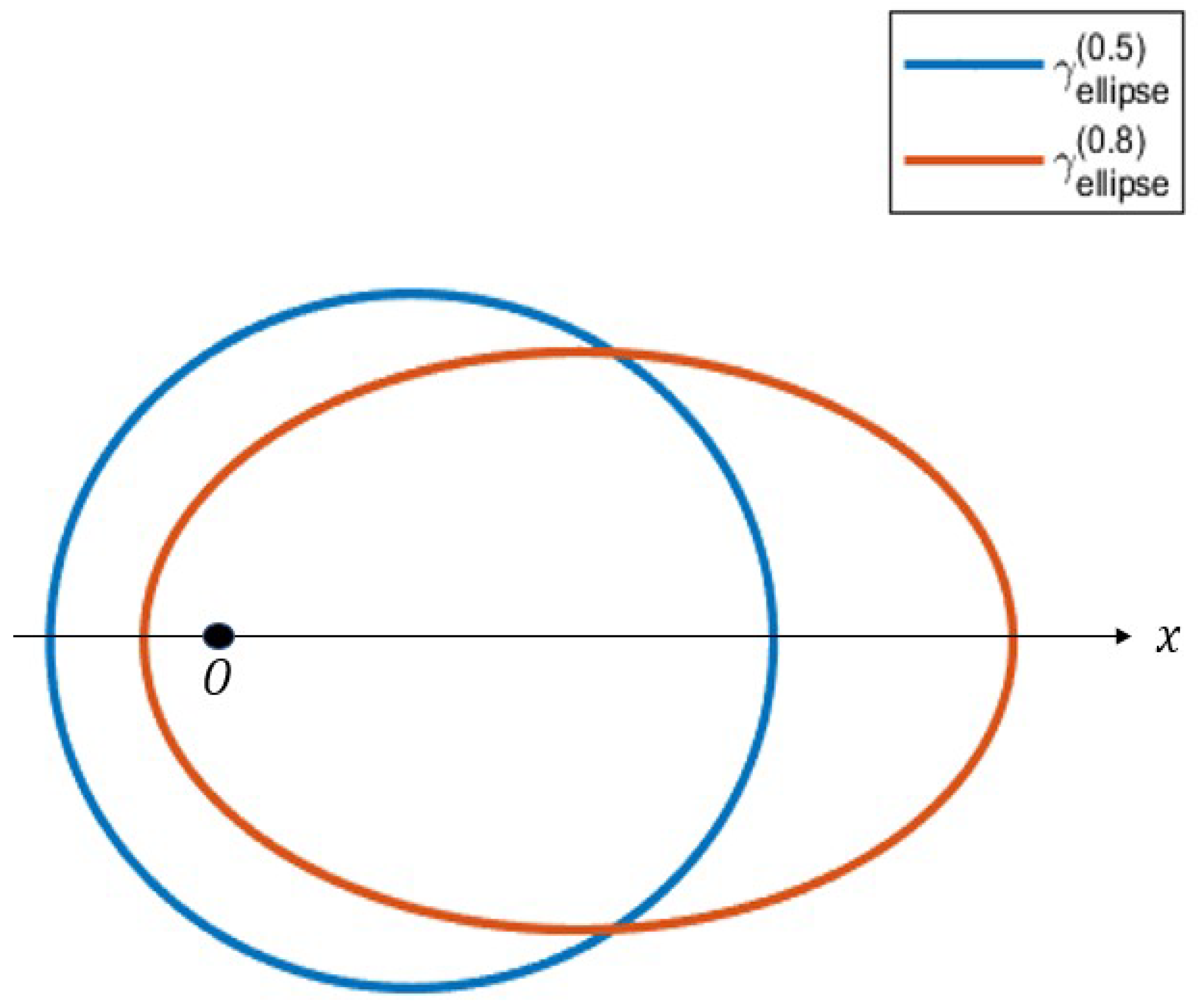
Figure 3 depicts 2 such ellipses with eccentricites ϵ 1 = 1 / 2 and ϵ 2 = 4 / 5 . As shown in the figure, the ellipses share a common focus at the origin, while the other focus moves away from the origin as ϵ increases. One can can show that the other focus lies on the x-axis at a distance 2 ϵ / π 1 / 2 1 ϵ 2 1 / 4 from the origin.
Example 3 
(Norm ball). A loop in the form of a p-norm ball for p R + may be defined as the set of points ( x , y ) satisfying | x | p + | y | p = 1 . We have, for any point ( x , y ) ( r cos ϕ , r sin ϕ ) on the p-norm ball,
r p | cos ϕ | p + r p | sin ϕ | p = 1 r = 1 | cos ϕ | p + | sin ϕ | p 1 / p .
We therefore have
γ norm ( p ) ( u ) = K p | cos ( 2 π u ) | p + | sin ( 2 π u ) | p 1 / p ,
where
K p = π 0 1 d u | cos ( 2 π u ) | p + | sin ( 2 π u ) | p 2 / p 1 / 2 .
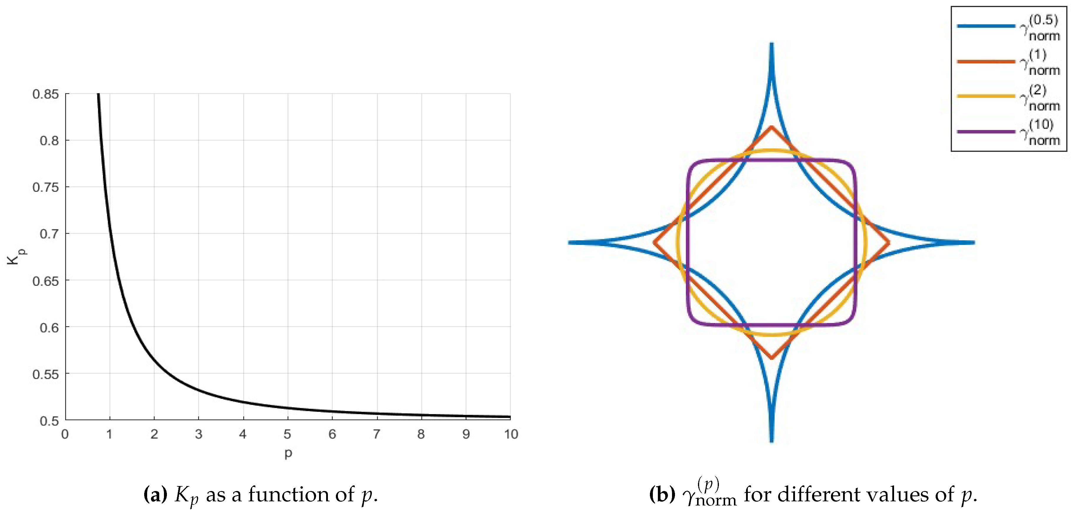
Figure 4a plots K p as a function of p , and Figure 4b depicts γ norm ( p ) for several values of p .
Remark 7. 
Using (30), one can write K p as
K p = π · 1 2 π · 8 · 0 1 1 + x p 2 / p d x 1 / 2 = 1 2 1 + 0 1 l = 1 ( 1 ) l x p l l ! q = 0 l 1 2 p + q d x 1 / 2
= 1 / 2 , p = 1 , 1 2 1 + l = 1 ( 1 ) l 1 l ! ( p l + 1 ) q = 0 l 1 2 p + q 1 / 2 , otherwise .
Closed forms of K p for various values of p can be obtained using the integral form (31) or the series form (32). For example, for p = 1 , (31) leads to
K 1 = 1 2 0 1 d x ( 1 + x ) 2 1 / 2 = 1 2 1 2 1 / 2 = 1 / 2 .
For p = 2 , (32) yields
K 2 = 1 2 1 + l = 1 ( 1 ) l 1 l ! ( 2 l + 1 ) q = 0 l 1 q + 1 1 / 2 = 1 2 1 + l = 1 ( 1 ) l 2 l + 1 1 / 2 = ( a ) 1 2 π / 4 1 / 2 = 1 / π ,
where ( a ) follows from the special case of Gregory’s series [29] for π / 4 , also known as the Leibniz formula for π .
For p = 4 , (31) yields
K 4 = 1 2 0 1 d x 1 + x 4 1 / 2 .
The expression I : = 0 1 1 / 1 + x 4 d x can be evaluated through the following sequence of steps. First, through the substitution u : = 1 / x , we have I = 1 1 / 1 + u 4 d u , whence, we have I = ( 1 / 2 ) 0 1 / 1 + x 4 d x . The substitution u : = 1 / 1 + x 4 leads to
1 1 + x 4 d x = 1 4 u 3 / 2 1 u 1 3 / 4 d u = 1 4 u 3 / 4 ( 1 u ) 3 / 4 ,
and therefore, we have
I = 1 2 · 1 4 0 1 u 3 / 4 ( 1 u ) 3 / 4 d u = ( a ) 1 8 B 1 / 4 , 1 / 4 = ( b ) Γ 1 / 4 2 8 · π ,
where in ( a ) , the beta function B ( m , n ) is defined, for ( m , n ) R + , as
B ( m , n ) = 0 1 u m 1 ( 1 u ) n 1 d u = 0 1 u n 1 ( 1 u ) m 1 d u ,
and in ( b ) , the gamma function Γ ( n ) is defined, for n R + , as
Γ ( n ) = 0 u n 1 exp u d u ,
with the well-known identity (see, for example, [30])
B ( m , n ) = Γ ( m ) · Γ ( n ) / Γ ( m + n ) .
We therefore have K 4 = 2 1 / 2 π 1 / 4 / Γ ( 1 / 4 ) .
Finally, using (32), we have
lim p K p = 1 / 2 .
All these results agree with the plot shown in Figure 4a.
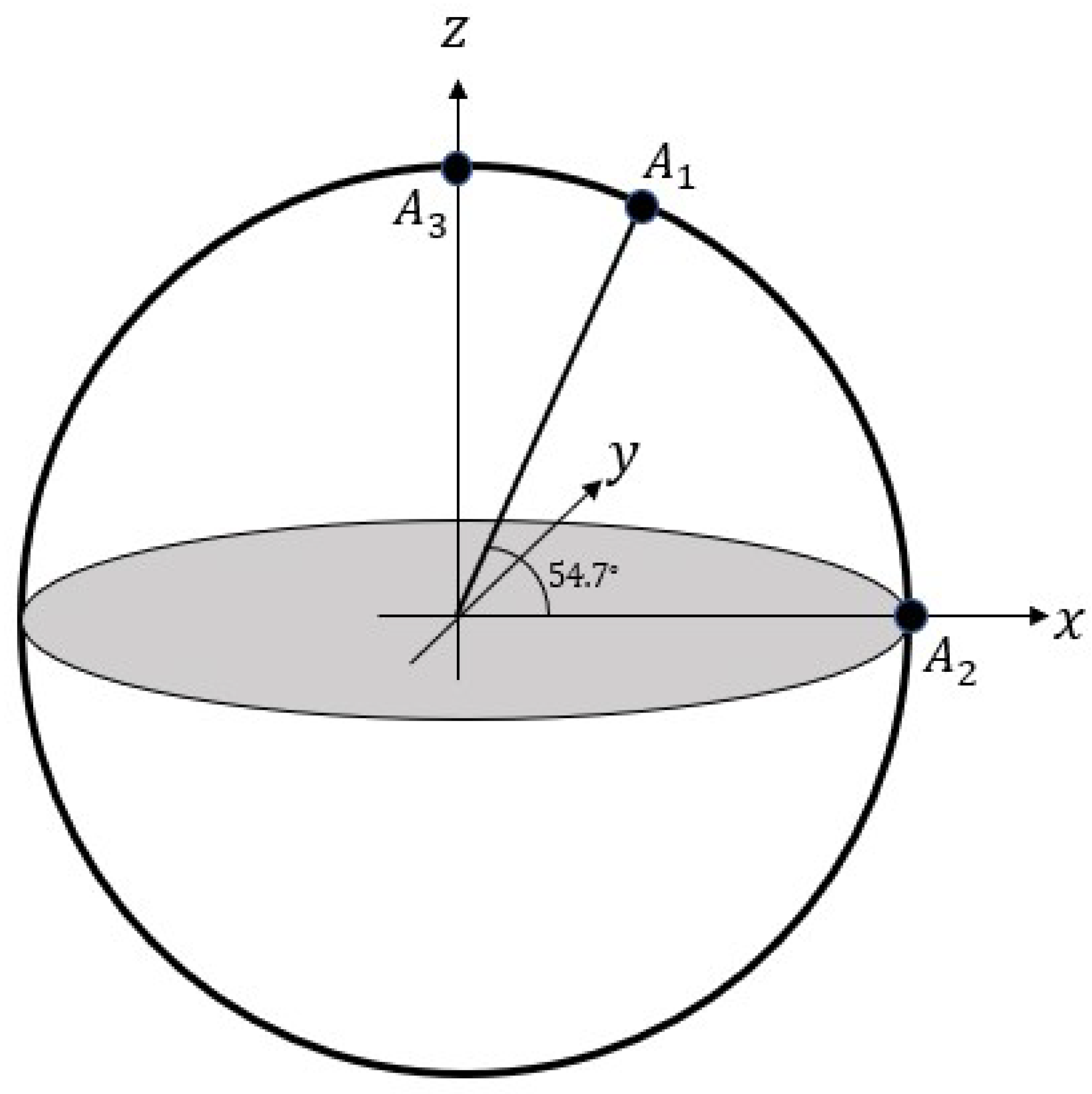
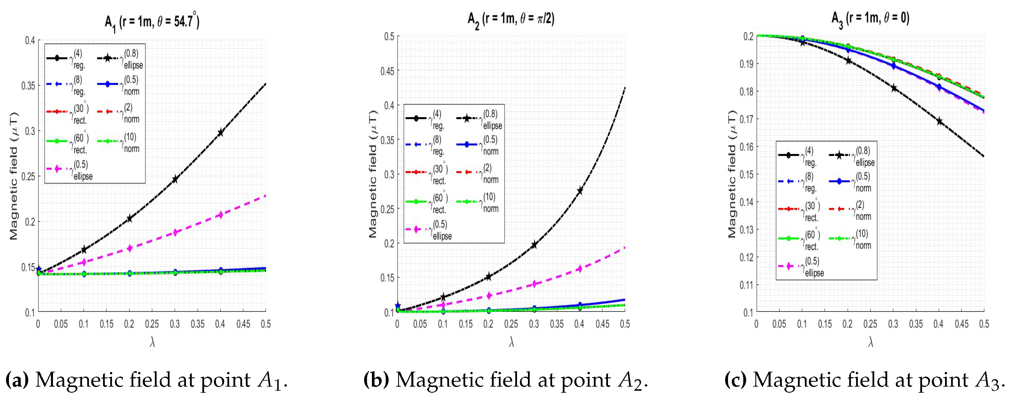
We now examine the magnetic fields produced by various loops defined in Examples 1, 2, and 3, as predicted by Lemma 3, as a function of the scaling parameter λ . To this end, we consider loops L ( λ ; γ ) with magnetic moment m = m z ^ and calculate the magnitude of the magnetic field produced at three different fixed points A 1 ,   A 2 , and A 3 , as demonstrated in Figure 5. In Figure 6, we plot the magnetic field (in μ T ) as a function of the scale λ , for λ ( 0 , 1 / 2 ] , when the magnetic moment magnitude equals 1 A · m 2 and the distance of the observation point from the origin is r = 1 m .
From Figure 6a, Figure 6b, and Figure 6c, we observe that loops of different shapes produce different magnetic fields at the same point for the same λ , as expected; in particular, the fields for γ ellipse ( 0 . 8 ) and γ ellipse ( 0 . 5 ) show the largest variation with λ , since the position of the center of symmetry of the loop is a function of λ , while all the other classes of loops examined have their center of symmetry at the origin. In spite of the different magnetic fields produced by the different loops for a finite λ , however, the magnetic field magnitudes converge to the same value for every loop as λ approaches zero, for each of the points A 1 ,   A 2 , and A 3 . This is a general result that will be theoretically established in Section 3.2 (Theorem 1). As a special case of Theorem 1, the convergence points in Figure 6a, Figure 6b, and Figure 6c can be inferred to be ( 2 / 10 ) μ T ,   0.1 μ T , and 0 . 2 μ T , respectively.

3. Current loop to ideal magnetic dipole

In this section, we demonstrate that the magnetic field and vector potential due to a plane current loop approach that of an ideal magnetic dipole as the loop shrinks to a point. We first establish the result for a circular loop in Section 3.1 and generalize the result to an arbitrary loop L ( λ ; γ ) in Section 3.2.

3.1. Circular loop

We will show that the magnetic field in Lemma 1 and the vector potential in Lemma 2 approach that of an ideal magnetic dipole as the radius a becomes small. To this end, we first prove the following lemma.
Lemma 4. 
For f ( 1 ) as defined in (7), we have
lim a 0 1 a f ( 1 ) 2 a r sin θ r 2 + a 2 = 3 π sin θ 2 r .
Proof. 
Since the integrand cos ϕ / 1 t cos ϕ 3 / 2 is bounded on the integration interval [ 0 , π ] for 0 < t < 1 , we have, by the dominated convergence theorem [30],
lim t 0 f ( 1 ) ( t ) = lim t 0 0 π cos ϕ 1 t cos ϕ 3 / 2 d ϕ = 0 π lim t 0 cos ϕ 1 t cos ϕ 3 / 2 d ϕ = 0 π cos ϕ d ϕ = 0 .
Further, since the integrand cos ϕ / 1 t cos ϕ 3 / 2 is continuously differentiable in both ϕ and t , we have
lim t 0 f ( 1 ) ( t ) = ( a ) 3 2 lim t 0 0 π cos 2 ϕ 1 t cos ϕ 5 / 2 d ϕ = ( b ) 3 2 0 π lim t 0 cos 2 ϕ 1 t cos ϕ 5 / 2 d ϕ = 3 2 0 π cos 2 ϕ d ϕ = 3 π 4 .
Here, ( a ) follows from Leibniz’s theorem on differentiation under the integral sign [31] and ( b ) again follows by the application of the dominated convergence theorem. Eqns (33), (34) and L’Hôpital’s rule [32] yields
lim t 0 f ( 1 ) ( t ) t = lim t 0 f ( 1 ) ( t ) = 3 π 4 .
We then have
lim a 0 1 a f ( 1 ) 2 a r sin θ r 2 + a 2 = ( a ) lim a 0 2 r sin θ r 2 + a 2 · lim t 0 f ( 1 ) ( t ) t = 2 sin θ r · 3 π 4 = 3 π sin θ 2 r ,
where ( a ) follows from the substitution t : = 2 a r sin θ / r 2 + a 2 in the second factor. This establishes the result. □
We are now ready to examine the behavior of the magnetic field obtained in Lemma 1 as the radius a grows small. We first note that from (8), application of the dominated convergence theorem yields
lim a 0 f ( 2 ) 2 a r sin θ r 2 + a 2 = 0 π d ϕ = π .
We then have, using (6),
lim a 0 B ( r ) = lim a 0 μ 0 m 4 π r 2 + a 2 3 / 2 · 2 π [ cos θ lim a 0 f ( 2 ) 2 a r sin θ r 2 + a 2 r ^ + r lim a 0 1 a f ( 1 ) 2 a r sin θ r 2 + a 2 sin θ lim a 0 f ( 2 ) 2 a r sin θ r 2 + a 2 θ ^ ] = ( a ) μ 0 m 4 π r 3 · 2 π π cos θ r ^ + 3 π sin θ 2 π sin θ θ ^ (36) = μ 0 m 4 π r 3 2 cos θ r ^ + sin θ θ ^ (37) = μ 0 4 π r 3 3 m · r ^ r ^ m .
Eqn (36) and (37) are the standard expressions for the field of an ideal magnetic dipole m placed at the origin (see, for example, [33,34]). Here, ( a ) follows from Lemma 4 and (35). We have thus established that a loop of steady current I creates the same field as an ideal magnetic dipole in the limit when the size of the loop goes to zero and the current I goes to , the magnetic moment m = π a 2 I being kept fixed.
Remark 8. 
The limiting behavior of the vector potential in (11) can also be readily established. We first note that, using similar reasoning as in the proof of Lemma 4, we have
lim a 0 2 π a sin θ f ( 3 ) 2 a r sin θ r 2 + a 2 = lim a 0 2 π a sin θ · 2 a r sin θ r 2 + a 2 · f ( 3 ) 2 a r sin θ r 2 + a 2 2 a r sin θ r 2 + a 2 = 4 π r f ( 3 ) ( 0 ) = 4 π r 0 π t cos u 1 t cos u 1 / 2 t 0 d u = 2 π r 0 π cos 2 u d u = 1 r .
Using (11), we then have
lim a 0 A ( r ) = lim a 0 μ 0 4 π r 2 + a 2 1 / 2 · lim a 0 2 π a sin θ f ( 3 ) 2 a r sin θ r 2 + a 2 m × r ^ = μ 0 4 π r 2 m × r ^ ,
which is the vector potential produced by a point magnetic dipole m placed at the origin (see, for example, [36]).

3.2. Arbitrary loop

We now turn to the case of an arbitrary loop L ( λ ; γ ) where γ is continuously differentiable almost everywhere in [ 0 , 1 ] and satisfies γ ( 0 ) = γ ( 1 ) . We have the following result.
Theorem 1. 
For r > 0 , the magnetic field B ( r , λ ; γ ) and the vector potential A ( r , λ ; γ ) as defined in Lemma 3 satisfy
lim λ 0 B ( r , λ ; γ ) = μ 0 m 4 π r 3 2 cos θ r ^ + sin θ θ ^ = μ 0 4 π r 3 3 ( m · r ^ ) r ^ m , lim λ 0 A ( r , λ ; γ ) = μ 0 4 π r 2 m × r ^ .
Proof. 
Using (18), we can write
B ( r , λ ; γ ) = μ 0 m 4 π λ ( 2 π λ cos θ · I 1 ( r , λ ; γ ) r ^ + I 2 ( r , λ ; γ ) 2 π λ sin θ · I 1 ( r , λ ; γ ) θ ^ + r cos θ · I 3 ( r , λ ; γ ) ϕ ^ ) ,
where
I 1 ( r , λ ; γ ) : = 0 1 γ ( u ) 2 λ 2 γ ( u ) 2 2 λ r γ ( u ) sin θ cos ( 2 π u ϕ ) + r 2 3 / 2 d u ,
I 2 ( r , λ ; γ ) : = 0 1 2 π r γ ( u ) cos ( 2 π u ϕ ) + r γ ( u ) sin ( 2 π u ϕ ) λ 2 γ ( u ) 2 2 λ r γ ( u ) sin θ cos ( 2 π u ϕ ) + r 2 3 / 2 d u ,
I 3 ( r , λ ; γ ) : = 0 1 2 π γ ( u ) sin ( 2 π u ϕ ) γ ( u ) cos ( 2 π u ϕ ) λ 2 γ ( u ) 2 2 λ r γ ( u ) sin θ cos ( 2 π u ϕ ) + r 2 3 / 2 d u .
At a high level, the proof will follow a similar overall approach as in the derivation in Section 3.1. We will first invoke the dominated convergence theorem evaluate the limit of the r ^ term directly, as well as to show that the quantities I 2 ( r , λ ; γ ) and r cos θ · I 3 ( r , λ ; γ ) each approach zero as λ 0 . We will then use L’Hôpital’s rule and Leibniz’s theorem on differentiation under the integral sign to evaluate the limits of the θ ^ and ϕ ^ terms. Let S [ 0 , 1 ] be a set of Lebesgue measure 1 such that γ is continuously differentiable everywhere on S . Then γ and γ are bounded almost everywhere on S (see, for example, [30]) and therefore, almost everywhere on [ 0 , 1 ] . Let M 1 and M 2 be these upper bounds on γ ( u ) and γ ( u ) , respectively. Then, for λ < r / 2 M 1 , the integrands in (40), (41), and (42) are bounded (uniformly in λ ) by 8 M 1 2 / r 3 ,   8 4 π 2 M 1 2 + M 2 2 1 / 2 / r 2 , and 8 4 π 2 M 1 2 + M 2 2 1 / 2 / r 3 , respectively, each of which is a finite constant and therefore yields a finite integral on [ 0 , 1 ] . Thus, using the dominated convergence theorem, we have
lim λ 0 I 1 ( r , λ ; γ ) = 0 1 lim λ 0 γ ( u ) 2 λ 2 γ ( u ) 2 2 λ r γ ( u ) sin θ cos ( 2 π u ϕ ) + r 2 3 / 2 d u = 1 r 3 0 1 γ ( u ) 2 d u = 1 π r 3 .
Similarly, we have
lim λ 0 I 2 ( r , λ ; γ ) = 0 1 lim λ 0 2 π r γ ( u ) cos ( 2 π u ϕ ) + r γ ( u ) sin ( 2 π u ϕ ) λ 2 γ ( u ) 2 2 λ r γ ( u ) sin θ cos ( 2 π u ϕ ) + r 2 3 / 2 d u = 1 r 2 0 1 2 π γ ( u ) cos ( 2 π u ϕ ) + γ ( u ) sin ( 2 π u ϕ ) d u = 1 r 2 γ ( u ) sin ( 2 π u ϕ ) u = 0 1 = 0 ,
since γ ( 0 ) = γ ( 1 ) , and
lim λ 0 r cos θ · I 3 ( r , λ ; γ ) = cos θ · 0 1 lim λ 0 2 π r γ ( u ) sin ( 2 π u ϕ ) r γ ( u ) cos ( 2 π u ϕ ) λ 2 γ ( u ) 2 2 λ r γ ( u ) sin θ cos ( 2 π u ϕ ) + r 2 3 / 2 d u = cos θ r 2 0 1 2 π γ ( u ) sin ( 2 π u ϕ ) γ ( u ) cos ( 2 π u ϕ ) d u = cos θ r 2 γ ( u ) cos ( 2 π u ϕ ) u = 0 1 = 0 .
We then have, using L’Hôpital’s rule,
lim λ 0 I 2 ( r , λ ; γ ) λ = lim λ 0 I 2 ( r , λ ; γ ) λ = ( a ) 3 2 lim λ 0 0 1 ( 2 π r γ ( u ) cos ( 2 π u ϕ ) + r γ ( u ) sin ( 2 π u ϕ ) λ 2 γ ( u ) 2 2 λ r γ ( u ) sin θ cos ( 2 π u ϕ ) + r 2 5 / 2 × 2 λ γ ( u ) 2 2 r γ ( u ) sin θ cos ( 2 π u ϕ ) ) d u = ( b ) 3 sin θ r 3 0 1 2 π γ ( u ) cos ( 2 π u ϕ ) + γ ( u ) sin ( 2 π u ϕ ) γ ( u ) cos ( 2 π u ϕ ) d u = 3 sin θ 2 r 3 0 1 2 π γ ( u ) 2 ( 1 + cos ( 4 π u 2 ϕ ) ) + γ ( u ) γ ( u ) sin ( 4 π u 2 ϕ ) d u = ( c ) 3 π sin θ r 3 0 1 γ ( u ) 2 d u + 3 sin θ 4 r 3 γ ( 0 ) 2 sin ( 2 ϕ ) γ ( 1 ) 2 sin ( 2 ϕ ) d v = 3 sin θ r 3 ,
where ( a ) follows from Leibniz’s theorem, since the integrand is continuously differentiable in both λ and u, ( b ) follows from the dominated convergence theorem (taking the limit inside the integral), and ( c ) follows from the substitution v : = γ ( u ) 2 sin ( 4 π u 2 ϕ ) . Following very similar steps, we have
lim λ 0 r cos θ · I 3 ( r , λ ; γ ) λ = lim λ 0 r cos θ I 3 ( r , λ ; γ ) λ = 3 cos θ 2 lim λ 0 0 1 ( 2 π r γ ( u ) sin ( 2 π u ϕ ) r γ ( u ) cos ( 2 π u ϕ ) λ 2 γ ( u ) 2 2 λ r γ ( u ) sin θ cos ( 2 π u ϕ ) + r 2 5 / 2 × 2 λ γ ( u ) 2 2 r γ ( u ) sin θ cos ( 2 π u ϕ ) ) d u = 3 cos θ sin θ r 3 0 1 2 π γ ( u ) sin ( 2 π u ϕ ) γ ( u ) cos ( 2 π u ϕ ) γ ( u ) cos ( 2 π u ϕ ) d u = 3 cos θ sin θ 2 r 3 0 1 2 π γ ( u ) 2 sin ( 4 π u 2 ϕ ) γ ( u ) γ ( u ) ( 1 + cos ( 4 π u 2 ϕ ) ) d u = 3 cos θ sin θ 4 r 3 γ ( 0 ) 2 cos ( 2 ϕ ) γ ( 1 ) 2 cos ( 2 ϕ ) d v γ ( 0 ) 2 γ ( 1 ) 2 d z = 0 .
Finally, using (39), we have
lim λ 0 B ( r , λ ; γ ) = μ 0 m 2 lim λ 0 I 1 ( r , λ ; γ ) ( cos θ r ^ sin θ θ ^ ) + μ 0 m 4 π lim λ 0 I 2 ( r , λ ; γ ) λ θ ^ + μ 0 m 4 π lim λ 0 r cos θ · I 3 ( r , λ ; γ ) λ ϕ ^ = ( a ) μ 0 m 2 π r 3 ( cos θ r ^ sin θ θ ^ ) + 3 μ 0 m 4 π r 3 sin θ θ ^ = μ 0 m 4 π r 3 ( 2 cos θ r ^ + sin θ θ ^ ) ,
which establishes the limit for B ( r , λ ; γ ) . Here, ( a ) follows by plugging in (43), (44), and (45). The limit of A ( r , λ ; γ ) can be demonstrated through a similar sequence of steps. □
Remark 9. 
It can be shown that the limiting behavior established in Section 3.1 and Section 3.2 holds for any loop with a piecewise continuous boundary, provided it can be continuously deformed to a point. We refer the reader to [35] for further reading.
Remark 10. 
As remarked in Section 2.2, the limiting magentic field at the points A 1 ,   A 2 , and A 3 in Figure 5 can be computed as a special case of Theorem 1. To see this, note that using Theorem 1, we have, for r > 0 ,
lim λ 0 B ( r , λ ; γ ) = μ 0 m 4 π r 3 4 cos 2 θ + sin 2 θ = μ 0 m 4 π r 3 3 cos 2 θ + 1 .
The values of cos 2 θ for A 1 ,   A 2 , and A 3 are, respectively, 1 / 3 ,   0 , and 1 , which, along with the numerical values m = 1 A · m 2 ,   r = 1 m , and μ 0 / 4 π = 10 7 T · m · A 1 , immediately yields the desired limiting values of the magnetic field magnitudes.

4. Discussions

The deep connection between currents and magnetic fields has been explored in great depth and its mysteries gradually revealed through extensive research since Ørsted’s experiment, culminating in Maxwell’s equations [10] and beyond. For a historical perspective of this gradual development, we refer the reader to [37] and references therein.
A popular current area of research specifically related to magnetic fields, is the search for the magnetic monopole [41] and the building of a theoretical framework [43] to study the consequences of the existence of the same [44].

References

  1. H. C. Ørsted, “Experiments on the effect of a current of electricity on the magnetic needles”, Annals of Philosophy 16:273, 1820.
  2. Brian Baigrie, Electricity and Magnetism: A Historical Perspective (Greenwood Press, 2007), pp. 7–8.
  3. P. Zhao, P. B. Vyas, S. Mcdonnell, P. Bolshakov-Barrett, A. Azcatl, C. L. Hinkle, P. K. Hurley, R. M. Wallace and C. D. Young, “Electrical characterization of top-gated molybdenum disulfide metal-oxide-semiconductor capacitors with high-k dielectrics”, Microelectronic Engineering 147, pp. 151-154, 2015. [CrossRef]
  4. P. B. Vyas, C. Naquin, H. Edwards, M. Lee, W. G. Vandenberghe, and M. V. Fischetti, “Theoretical simulation of negative differential transconductance in lateral quantum well nMOS devices”, Journal of Applied Physics 121, pp. 044501, 2017. [CrossRef]
  5. Étienne Du Trémolet de Lacheisserie, Damien Gignoux, and Michel Schlenker, Magnetism: Fundamentals (Springer, 2005), pp. 3–6.
  6. Pratik B. Vyas, Maarten L. Van de Put, and Massimo V. Fischetti, “Simulation of Quantum Current in Double Gate MOSFETs: Vortices in Electron Transport”, 2018 International Conference on Simulation of Semiconductor Processes and Devices (SISPAD), pp. 1-4, 2018.
  7. G. A. G. Bennet, Electricity and Modern Physics (2nd Ed.) (UK:Edward Arnold, 1974).
  8. Pratik B. Vyas, Maarten L. Van de Putt, and Massimo V. Fischetti, “Quantum Mechanical Study of Impact of Surface Roughness on Electron Transport in Ultra- Thin Body Silicon FETs”, 2018 IEEE 13th Nanotechnology Materials and Devices Conference (NMDC), pp. 1-4, 2018.
  9. James Clerk Maxwell, On Physical Lines of Force (New York: Dover Publications, 1890).
  10. James Clerk Maxwell, “A dynamical theory of the electromagnetic field”, Philosophical Transactions of the Royal Society of London, 155, pp. 459–512, 1865. [CrossRef]
  11. Ali Saadat, Pratik B. Vyas, Maarten L. Van de Put, Massimo V. Fischetti, Hal Edwards, and William G. Vandenberghe “Channel Length Scaling Limit for LDMOS Field-Effect Transistors: Semi-classical and Quantum Analysis”, 2020 32nd International Symposium on Power Semiconductor Devices and ICs (ISPSD), pp. 443-446, 2020.
  12. Pratik B. Vyas, Maarten L. Van de Put, and Massimo V. Fischetti, “Master-Equation Study of Quantum Transport in Realistic Semiconductor Devices Including Electron-Phonon and Surface-Roughness Scattering”, Phys. Rev. Appl. 13, pp. 014067, 2020. [CrossRef]
  13. Pratik B. Vyas, Ninad Pimparkar, Robert Tu, Wafa Arfaoui, Germain Bossu, Mahesh Siddabathula, Steffen Lehmann, Jung-Suk Goo, and Ali B. Icel, “Reliability-Conscious MOSFET Compact Modeling with Focus on the Defect-Screening Effect of Hot-Carrier Injection”, 2021 IEEE International Reliability Physics Symposium (IRPS), pp. 1-4, 2021.
  14. Damian P. Hampshire, “A derivation of Maxwell’s equations using the Heaviside notation”, Philosophical Transactions of the Royal Society A: Mathematical, Physical and Engineering Sciences 376(2134), 2018. [CrossRef]
  15. Herbert Goldstein, Classical Mechanics (2nd ed.) (Addison–Wesley Publishing Co., 1980), Chap. 7: “Special Relativity in Classical Mechanics”.
  16. Albert Einstein, Relativity: The Special and the General Theory: Reprint of 1920 translation by Robert W. Lawson ed. (Routledge, 2001).
  17. Pratik B. Vyas, Ashish Pal, Gregory Costrini, Plamen Asenov, Sarra Mhedhbi, Charisse Zhao, Victor Moroz, Benjamin Colombeau, Bala Haran, El Mehdi Bazizi, and Buvna Ayyagari-Sangamalli, “Materials to System Co-optimization (MSCOTM) for SRAM and its application towards Gate-All-Around Technology”, 2023 International Conference on Simulation of Semiconductor Processes and Devices (SISPAD), pp. 53-56, 2023.
  18. Roald K. Wangsness, Electromagnetic Fields (2nd Ed.) (New York:Wiley, 1986).
  19. Harvey R. Brown, “The origins of length contraction–I: the FitzGerald-Lorentz deformation hypothesis”, Amer. Journ. Phys. 69(10), pp. 1044–1054, 2001. [CrossRef]
  20. Shaul Katzir, “Poincaré’s Relativistic Physics: Its Origins and Nature”, Phys. Perspect. 7(3), pp. 268–292, 2005. [CrossRef]
  21. Charles Coulston Gillispie, The Edge of Objectivity: An Essay in the History of Scientific Ideas (Princeton University Press, 1960), p. 408.
  22. Jakob Laub, “Über die experimentellen Grundlagen des Relativitätsprinzips”, Jahrbuch der Radioaktivität und Elektronik 7, pp. 405–463, 1960.
  23. David Mattingly, “Modern Tests of Lorentz Invariance”, Living Rev. Relativ. 8(3):5, 2005. [CrossRef]
  24. Ch. Eisele, A. Yu. Nevsky, and S. Schillerv, “Laboratory Test of the Isotropy of Light Propagation at the 10-17 level”, Phys. Review Lett. 103(9):090401, 2009. [CrossRef]
  25. Albert A. Michelson and Edward W. Morley, “On the Relative Motion of the Earth and the Luminiferous Ether”, Amer. Journ. Science 34(203), pp. 333–345, 1887. [CrossRef]
  26. B. P. Abbott et al. (LIGO Scientific Collaboration and Virgo Collaboration), “GW151226: Observation of Gravitational Waves from a 22-Solar-Mass Binary Black Hole Coalescence”, Phys. Rev. Lett. 116(24):241103, 2016. [CrossRef]
  27. T. S. Jaseja, A. Javan, J. Murray, and C. H. Townes, “Test of Special Relativity or of the Isotropy of Space by Use of Infrared Masers”, Phys. Rev. 133(5a), pp. 1221–1225, 1964. [CrossRef]
  28. S. Chowla and A. Selberg, “On Epstein’s Zeta Function (I)”, Proceedings of the National Academy of Sciences 35(7):373, 1949. [CrossRef]
  29. R. C. Gupta, “The Madhava–Gregory series”, The Mathematics Education 7, pp. B67–B70, 1973.
  30. H. L. Royden, Real Analysis (Prentice Hall, 1988).
  31. Murray H. Protter and Charles B. Morrey, Jr., Intermediate Calculus (2nd Ed.) (New York: Springer, 1985), pp. 421–426.
  32. A. E. Taylor, “L’Hospital’s rule”, Amer. Math. Monthly 59(1), pp. 20–24, 1952.
  33. David J. Griffiths, Introduction to Electrodynamics (Boston:Pearson, 2013).
  34. J. D. Jackson, Classical Electrodynamics (3rd ed.) (New York:Wiley, 1999).
  35. John W. Morgan, “Recent progress on the Poincaré conjecture and the classification of 3-manifolds”, Bull. Amer. Math. Soc. (N.S.) 42(1), pp. 57–78, 2005.
  36. Tai L. Chow, Introduction to electromagnetic theory: a modern perspective (Jones & Bartlett Learning, 2006).
  37. E. W. Lee, Magnetism, An Introductory Survey (Dover Publications Inc., 1970).
  38. Richard P. Feynman, “Space–Time Approach to Quantum Electrodynamics”, Phys. Rev. 76(6), pp. 769–789, 1949. [CrossRef]
  39. Pratik B. Vyas, Charisse Zhao, Sefa Dag, Ashish Pal, El Mehdi Bazizi, and Buvna Ayyagari-Sangamalli, “Next Generation Gate-all-around Device Design for Continued Scaling Beyond 2 nm Logic”, 2023 International Conference on Simulation of Semiconductor Processes and Devices (SISPAD), pp. 57-60, 2023.
  40. R. Courant and D. Hilbert, “Methods of Mathematical Physics”, Interscience, New York, 1966.
  41. C. Castelnovo, R. Moessner, and S. L. Sondhi, “Magnetic monopoles in spin ice”, Nature 451(7174), pp. 42–45, 2008. [CrossRef]
  42. Pratik B. Vyas, Charisse Zhao, Sefa Dag, Ashish Pal, El Mehdi Bazizi, and Buvna Ayyagari-Sangamalli, “Modeling of SiC transistor with counter-doped channel”, Solid State Electronics 200, pp. 108548, 2023. [CrossRef]
  43. Xiao-Gang Wen and Edward Witten, “Electric and magnetic charges in superstring models”, Nuclear Phys. B 261, pp. 651–677, 1985. [CrossRef]
  44. M. W. Ray, E. Ruokokoski, S. Kandel, M. Möttönen, and D. S. Hall, “Observation of Dirac monopoles in a synthetic magnetic field”, Nature 505(7485), pp. 657–660, 2014. [CrossRef]
  45. Erwin Kreyszig, Advanced Engineering Mathematics (3rd ed.) (New York: Wiley, 1972).
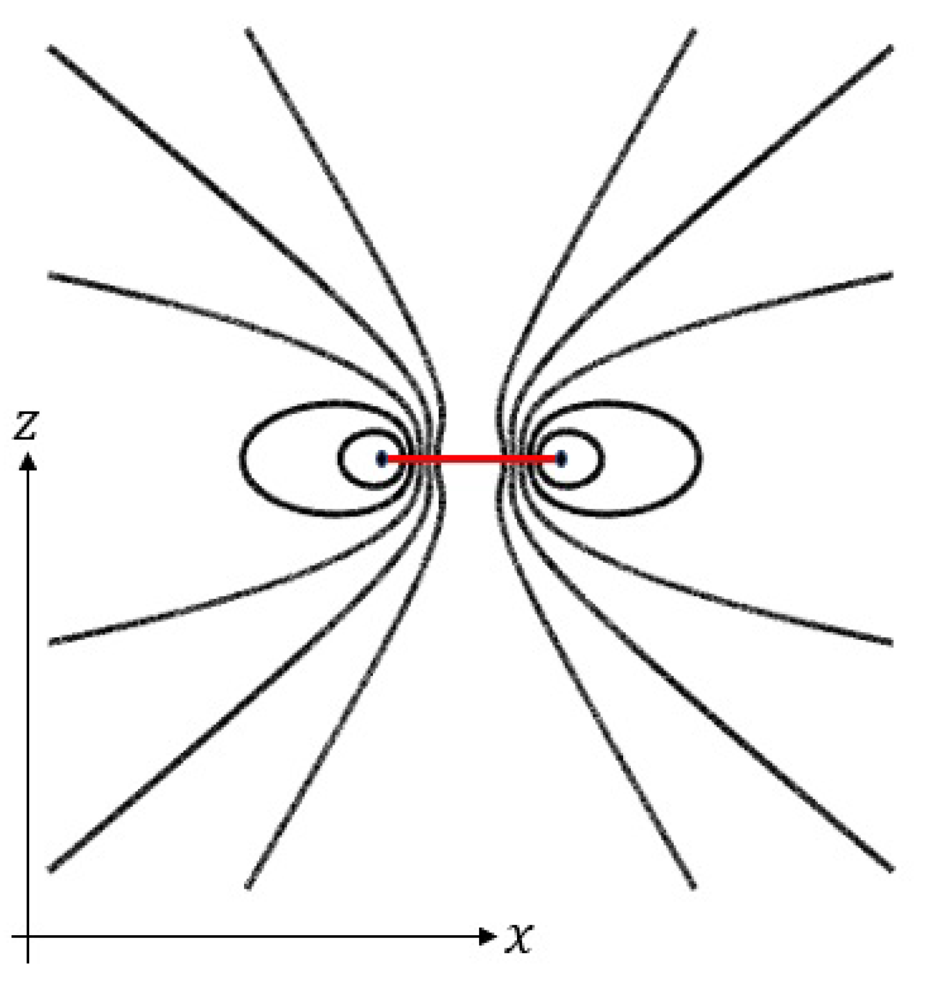
Figure 1. Magnetic field lines.
Preprints 97281 g001
Figure 2. Polygons.
Figure 2. Polygons.
Preprints 97281 g002
Figure 3. γ ellipse ( ϵ ) .
Preprints 97281 g003
Figure 4. p-norm balls.
Preprints 97281 g004
Figure 5. Magnetic field B calculated at three points A 1 ,   A 2 ,   A 3 .
Preprints 97281 g005
Figure 6. Magnetic field as function of scale λ .
Preprints 97281 g006
Disclaimer/Publisher’s Note: The statements, opinions and data contained in all publications are solely those of the individual author(s) and contributor(s) and not of MDPI and/or the editor(s). MDPI and/or the editor(s) disclaim responsibility for any injury to people or property resulting from any ideas, methods, instructions or products referred to in the content.
Copyright: This open access article is published under a Creative Commons CC BY 4.0 license, which permit the free download, distribution, and reuse, provided that the author and preprint are cited in any reuse.
Prerpints.org logo

Preprints.org is a free preprint server supported by MDPI in Basel, Switzerland.

Subscribe

© 2024 MDPI (Basel, Switzerland) unless otherwise stated