1. Introduction
From the creation of the laser, the initial goal was to create a laser with ever more power and higher beam quality [
1]. However, when you try to increase one parameter, the other starts to degrade. For high-power approaches large pump areas are used and multimode operation is achieved, while for more delicate applications a single transverse mode operation is required. For that selective discrimination of higher-order modes is required, this induces losses in the resonator and reduces the output power. In order to further improve both laser parameters some aspects of the laser have to be modified. Also, a Gaussian shape isn’t the best option for all applications and other shapes are desirable. For a more uniform laser microfabrication, a flat-top beam gives better results and more control [
2,
3]. For high aspect ratio structures a Bessel beam is required [
4]. However, most of the time resonators are designed to output a fundamental Gaussian mode. There are three ways to modify the beam spatial parameters. One is to simply shape the freely propagating beam to suit your needs [
5], the second is to shape the pump beam to have a different gain distribution and gain guiding in the resonator (extracavity modulation), and the third, is to shape the beam inside the cavity and force certain modes to resonate over others (intracavity modulation). Extracavity modulation is more related to better control of thermal effects [
6] and energy extraction [
7]. Intracavity is mostly used for mode selection where gain or loss can be spatially controlled to select the desired mode [
8,
9,
10] of the outputting laser and higher energy extraction efficiency from the lasing medium [
11,
12], by using top-hat or flat-top beam profiles when the beam propagates through the gain region. The selection of passive [
13] or active [
14,
15] elements can be used. Intracavity modulation is beneficial because the resonator acts as a filter and purifies the oscillating mode [
16]. For example, the needed flat-top beam is generally obtained by using diffractive optics in a reshaping operation during free propagation of the beam. In this case, the resulting flat-top profile occurs only in the focal plane of the focusing lens, and its vicinity. The beam is not invariant under propagation. By using intracavity structuring a shape-invariant flat-top beam can be achieved from a mixing of
and
beams [
17].
The newer microchip lasers are currently of great interest for their potential applications in, for example, optical data storage and transfer and metrology [
18]. A microchip laser is composed of a thin slab of an amplifying medium with Bragg mirrors deposited upon both faces [
19,
20]. The pumping mechanism generally consists of a laser diode with some transverse profile that leads to gain guiding and index guiding effects [
21,
22]. In these lasers, the existence of confined transverse modes is due to the pump profile unlike in conventional lasers, for which the mode structure is determined mainly by the geometrical characteristics of the cavity [
23] and the output coupling mirror. Surface-emitting lasers and their newer versions the membrane external cavity lasers have the ability to both, have higher beam quality and higher output power [
24]. These types of structures should have better power scalability due to much smaller thermal stresses [
25]. A suggested two-dimensional (2D) periodic modulation of the optical gain and refractive index can improve the quality of the beam amplified in the BA device [
26]. The reported angular filtering of the emission is strongly related to the particular selection of both longitudinal and lateral modulation periods. Diffraction manipulation affects primarily the linear propagation of light beams in bulk photonic crystals [
27].
The first structured scalar beams from a laser were created by amplitude control inside the cavity, using wires to produce Hermite–Gaussian modes [
28]. Photonic crystal (PhC) spatial filters are a potential solution to suppress multi-mode operation in micro-cavity lasers increasing the output beam spatial quality and its brightness [
29,
30,
31]. Photonic structures on top of vertical surface emitting lasers (VECSELs) also showed promising results for maintaining lower mode operation in the new structure called photonic crystal surface-emitting lasers (PCSELs) [
32,
33]. In this work, we investigate whether the same operation can be performed directly by a structured intensity profile of a pump beam.
2. Methodology and the Laser Setup
2.1. Models for Phase Mask Selection
An approach has been shown for passive laser beam combining using plane-parallel intracavity interferometric combiners [
34]. With this approach, the efficient coherent combining of 16 solid-state laser channels operating at single transverse Gaussian modes has been shown with an efficiency of
. The beam quality of the combined beam was calculated to be
, practically the same as the single-channel beam quality. Talbot resonators [
35,
36], have been shown to phase-lock separate yet coherent sources. Not phase-locked lasers usually exhibit high output powers but low brightness whereas phase-locked also provide a good beam quality. One possibility to phase-lock an array of individual emitters is the use of the Talbot effect. It describes the self-imaging of a coherent, periodic wavefield after a certain distance of free space propagation. In the ideal case of a coherent wavefield with wavelength
and a spatial period
d the field distribution self-images completely after the Talbot distance:
This effect has a major influence on the transversal mode structure when it arises inside the cavity of a laser array [
37]. In our case, a linear periodic intensity distribution of the pump beam acts as multiple coherent emitters. The spacing period can be tuned by changing the appropriate hologram. We follow a similar approach used in [
38] to consider broad area semiconductor (BAS) amplifiers of moderate length with a 2D, longitudinal, and transverse, modulation of the electrical contacts. The idea is that by shaping the pump beam, we may create arbitrarily good overlap between the pump and the desired mode, and thus force the laser oscillation on a transverse mode of higher order rather than the usual (low order) Gaussian mode. One may thus think of the pump beam intensity profile as a parameter of transverse mode control not often exploited in laser resonator experiments. In this case, the spatial structure of the pump beam creates the transverse periods, and the resonator length is used as the longitudinal period. As the laser oscillates in the cavity with each return it feels the intensity distribution of the pump source. Feedback between the pump structure and resonating mode should lead to a decrease in divergence. This can be represented by a parameter Q:
where
is the transverse and
is the parallel spatial periods. The periodic pump would act as a spatial filter integrated into the laser cavity. The idea is based on a selective deflection of the angular components of the light propagating through a 2-D photonic structure: The angular components of the incident light resonant with the transverse and longitudinal periodicities of the structure diffract efficiently and are deflected from the zero-diffraction order of the transmitted beam. Previous studies show that a periodic gain/loss (GL) modulation on the wavelength scale can lead to particular beam propagation effects, such as self-collimation, and spatial (angular) filtering. While for sufficiently long devices the beam profile is solely determined by the most amplified mode, for shorter or moderate lengths a comprehensive analysis of the mode growth shows that other modes contribute to determining the final beam shape. In this way, a proper choice of spatial periods can lead to the narrowing of the central far-field component while substantially improving the spatial structure of the amplified beam.
2.2. Experimental Setup
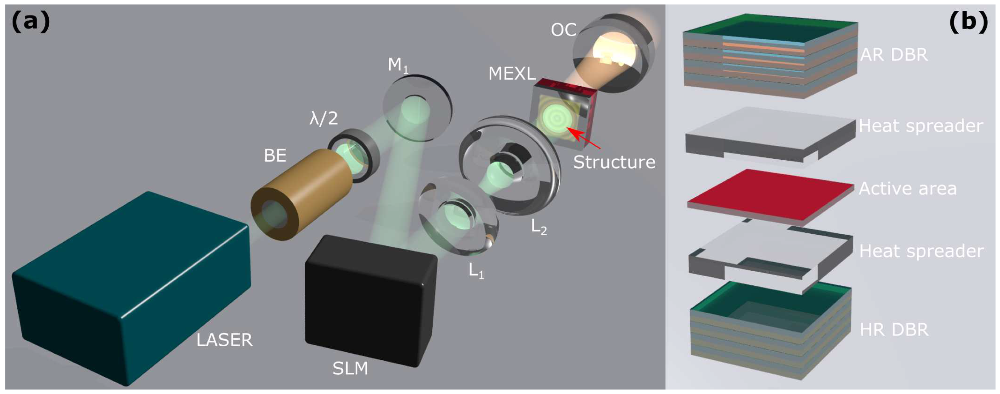
In this work, we used a fiber-coupled 808 nm diode laser as the pump source. It can be run at continuous wave (CW) or quasi-continuous wave (QCW) regimes, by using pulse width modulation. A thin membrane external cavity surface emitting laser (MECSEL) was used as the active medium with a thickness of 1
Figure 1b. We used a liquid crystal on a silicon spatial light modulator (SLM) to act as the beam-shaping element of the pump beam. It is a two-dimensional
pixel array with a pixel size of 8
that allows control of the phase of the laser beam by delaying it locally with each pixel. This makes it possible to distort the laser wavefront, which is a surface of the same phase. This changes the further propagation of the laser and due to the interference, a dynamically controlled and variable intensity distribution is formed. Exploiting the fact that adjacent pixels shifted anti-phase allows the generation of destructive interference, it is possible to locally reduce the intensity and perform amplitude modulation of the laser with SLM. A magnifying telescope of two lenses 1000 mm and 30 mm/15 mm was used in a 4F setup to scale and relay the structured intensity distribution to the active area of the MECSEL chip. For experiments a QCW regime was used with a pulse duration of 200
and a repetition rate of
In the case when a flat output coupling mirror is used, the entire resonator is only stabilized by the thermal lens in this very thin MECSEL chip. Even though the entire structure is
thick with an active area of just around 1
and fast heat dissipation, the thermal lens still arises and stabilizes laser operation. The flat output coupling mirror (OC) with reflectivity of
was placed with an air gap of 200
for a total physical resonator length of 1.2 mm.
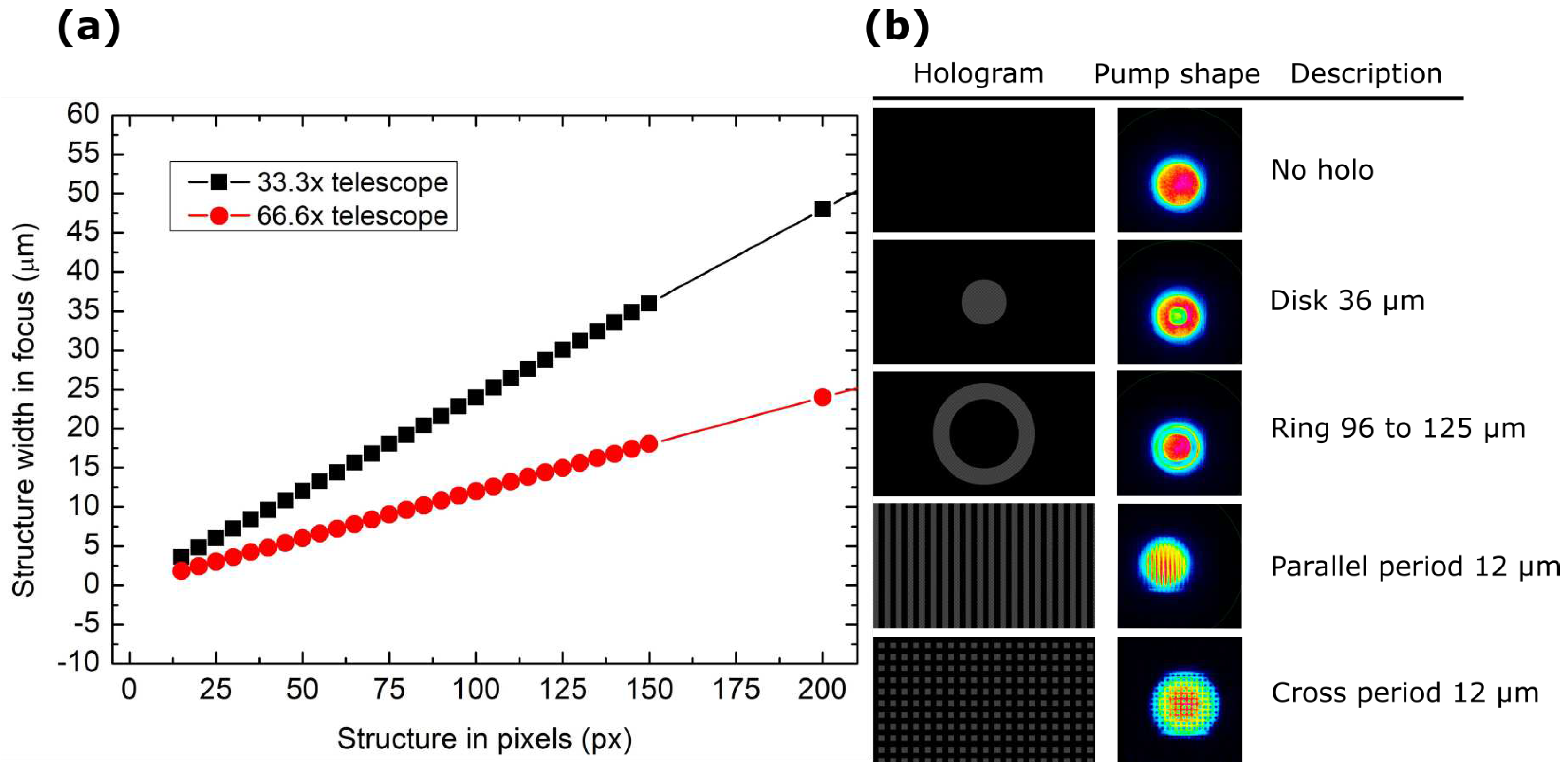
The telescopes used in the experiment were comprised of magnifying 4F systems
Figure 2a, the corresponding pixel count in the amplitude mask on the SLM screen corresponded to a certain size in
in the focal plane and scaled linearly. Variations of the holograms used in the experiment are shown in
Figure 2b. The main types comprise ring holograms that selectively attenuate the edges of the pump beam, or periodic line patterns with varying widths, that etch out linear intensity regions.
3. Results
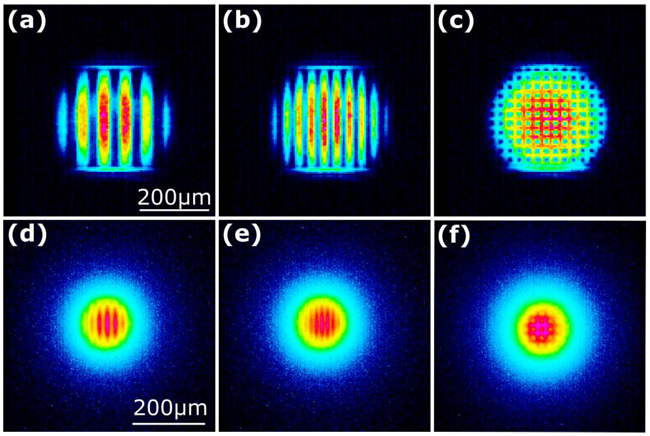
To see the effects of the structured pump on the active layer itself, the luminescence of the beam shape was visualized onto a CCD beam profiler by the use of a lens in a double focal length setup (2F2F). As seen in
Figure 3 the pump beam shape is visible on the active media. However, the contrast between intense regions and dark regions is not as clear as on the pump beam itself. This can be due to the diffusion of the carriers in the active areas of quantum wells. This does give a limit to how dense the pump structures can be before diffusion equalizes the intensity distribution.
Due to the big parameter space various pumping intensity shapes were chosen for evaluation
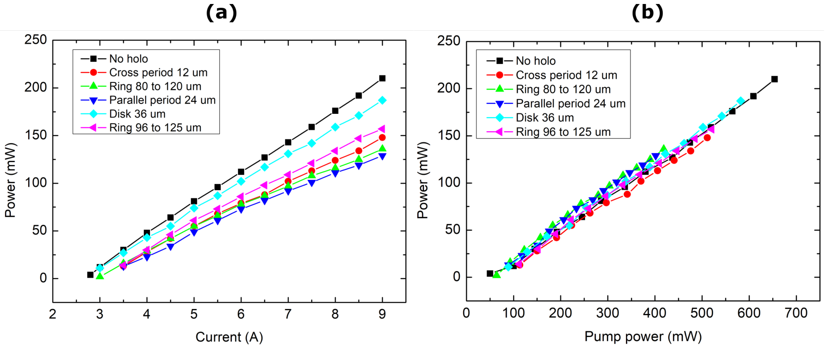
Figure 2. Because we are using amplitude modulation, the part that sees destructive interference also diffracts away from the optical chain and doesn’t propagate toward the active media. Therefore, if we normalize each used beam shape with the actual optical power impinging on the MECSEL chip, we see that the conversion efficiency remains the same regardless of the shape
Figure 4. Pumping was done
wavelength with a
repetition rate where the ON cycle was
spot size from a 66.6x reducing telescope made from a pair of lenses with 1000 mm and 15 mm focal lengths. The acquired conversion efficiency of
. All parameters were measured in the same manner so systemic errors were identical. The beam width of the output beam was measured at the focal plane of a 50 mm focal lens. The lens was placed 150 mm from the resonator’s OC in all cases. The far field intensity distribution was measured at two different planes 5 mm and 10 mm away from the focal spot.
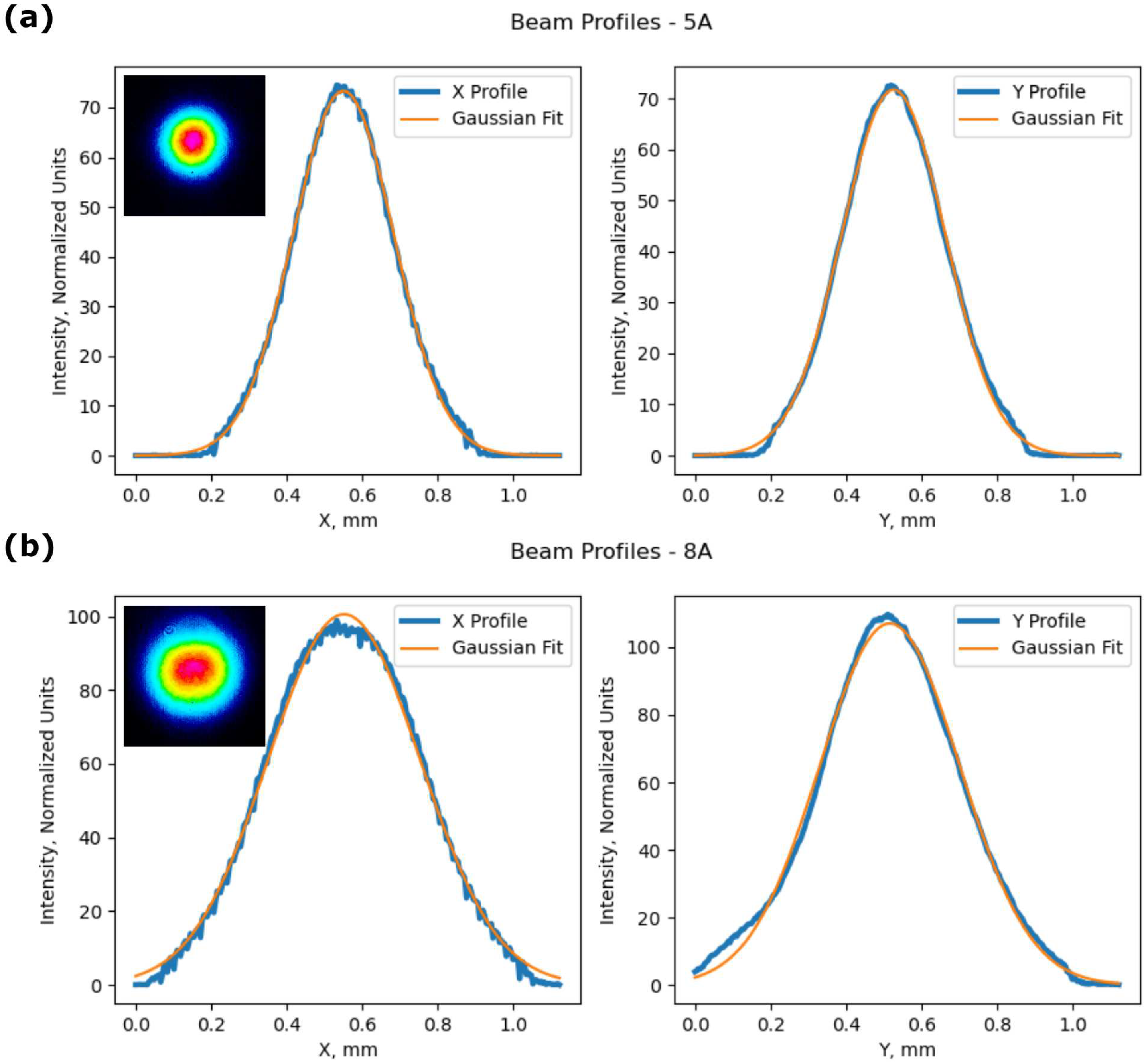
The oscillating fundamental resonator mode must be much smaller than the pump beam in order to get higher-order beam shapes to oscillate. If the fundamental oscillating modes and pump beam sizes match no higher modes are formed and just a decrease in power is present due to the lower coupling of the beam. They all follow the same pump power generation path with similar divergence and focusing parameters. The output beam mostly remained a
mode with a slight decrease in energy in the central region at higher pumping (
Figure 5). For a
.gif of the changing 2D XY intensity distribution from an increase in pump power see (Supplementary Video S1) . The shape oscillates by becoming more elliptical in one axes then, becoming circular and elliptical in the perpendicular. At higher powers the maxima of the output beam flatten out it no longer is a pure
, there are higher modes mixed in. This gives rise to a decrease in the overall brightness.
For the brightness calculations of the laser beam, the expression used was:
where
is the beams divergence and
is the beam waist at focus. From
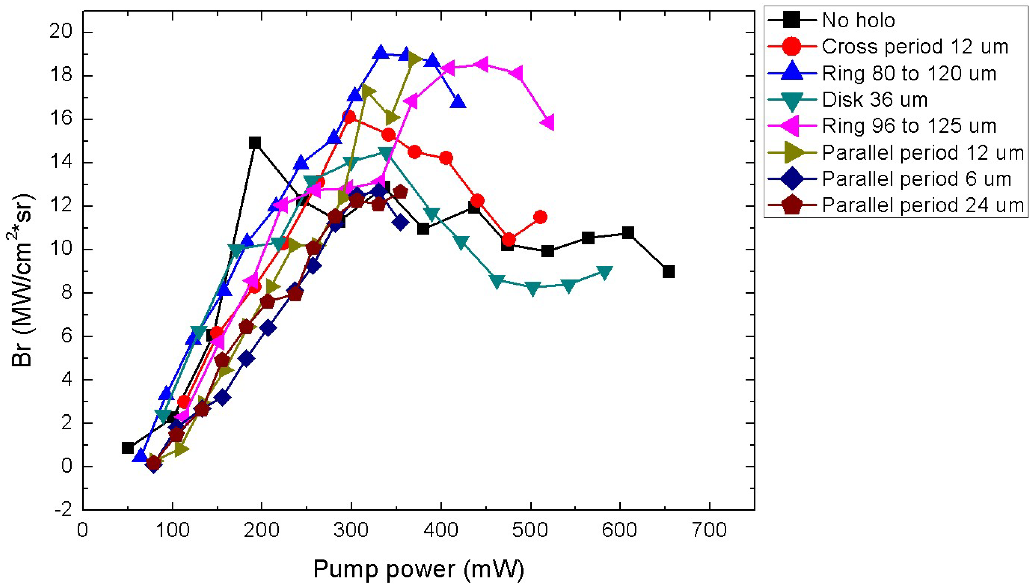
Figure 6 we can see a brightness peak at a pump power of around
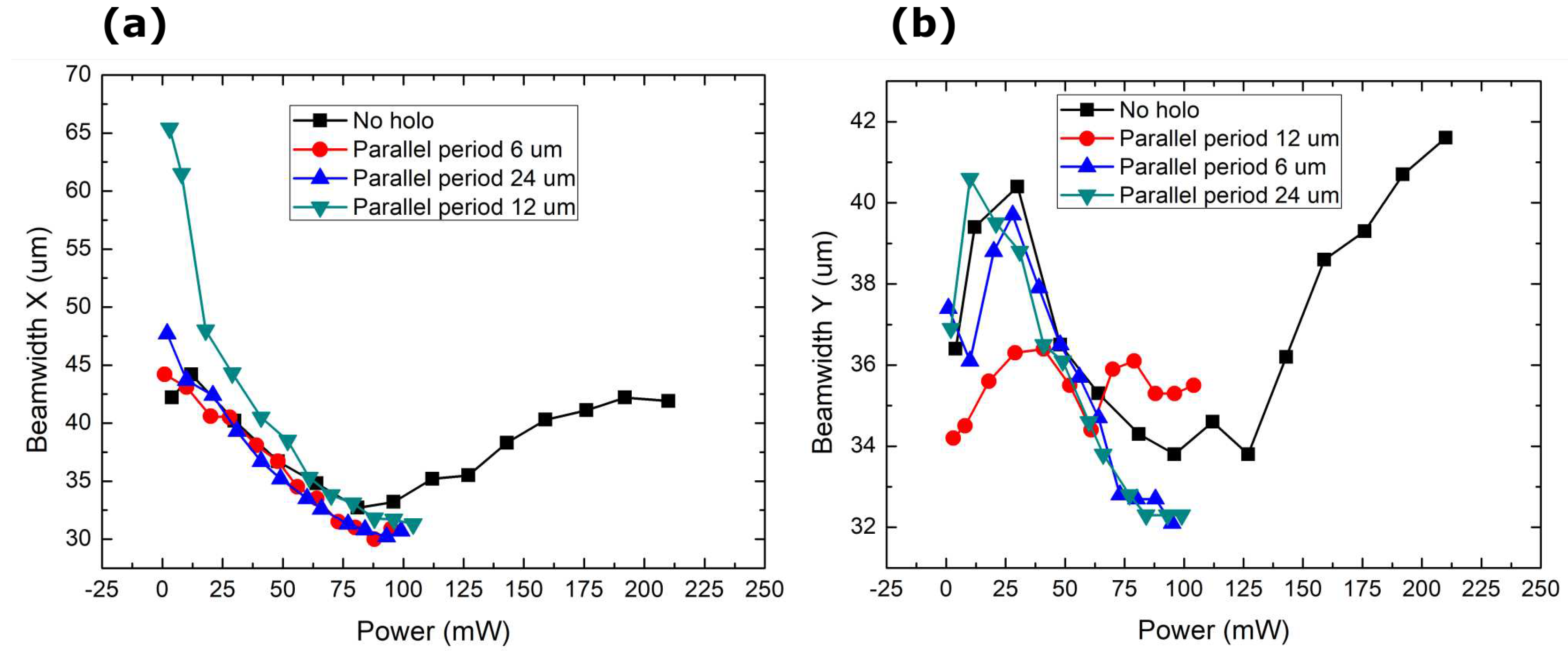
. Around this power level, the far field of the generated beam started to have a flatter intensity distribution with a further increase in power giving an intensity dip in the center. This could be the formation of higher-order modes. From the power curves, we note that the output power continues to be linearly increased with the pump power. Saturation was not reached in this experiment. The only source of a decrease in brightness is the degradation of the quality of the beams. The divergence of the beams increases almost linearly with the oscillations due to the shifting ellipticity in the far field, while the beam’s ability to focus initially gets better (
Figure 8) and the focal spot gets tighter, but as higher modes start to form inside the resonator, the spot sizes start to increase.
A further look at the 1D periodic line pump divergence in
Figure 7 we see a peculiar phenomenon where the divergence of the beam seems to not change for the period of
. If we look back at Equation (
2). Resonator length =
MECSEL structure +
air gap, the true structure of the MECSEL is unknown, but taking a guess for the average refractive index of 3 we get that: For the case where
the longitudinal period is
, and for the case where
. Therefore, the stagnation in the divergence could be attributed to the longitudinal and transverse periods matching. Where the use of
and
periods are too far from the
relation. However, the power scaling was not sufficient to generate clearly visible
and higher order modes.
Figure 6.
MECSEL laser brightness dependence on pump beam average power. No holo is the case where SLM was used as a reflecting mirror with no modulation.
Figure 6.
MECSEL laser brightness dependence on pump beam average power. No holo is the case where SLM was used as a reflecting mirror with no modulation.
Figure 7.
Change in the divergence of the generated laser radiation with power in X and Y direction.
Figure 7.
Change in the divergence of the generated laser radiation with power in X and Y direction.
Figure 8.
Change in focal beam size of the generated laser radiation with power in X and Y direction.
Figure 8.
Change in focal beam size of the generated laser radiation with power in X and Y direction.
Curved resonator setup.To see a change in the output beam shape a curved OC with a radius of curvature of 100 mm was used instead of a flat that has been talked about up until now. This gives a Flat-Concave resonator setup. The resonator length of
gives a mode size on the MECSEL chip of
. The pump spot from a 30 mm lens is 340
is larger than the fundamental oscillating mode size for the curved mirror case. A curved mirror already selects the modes that will oscillate inside a resonator, but by using an elongated pump, only modes that go above the threshold can lase. Then by rotating the pump shape with the holograms, a selection of modes is possible. Although the shape is determined by the resonator itself. An asymmetric pump profile in an ellipse gives rise to asymmetrical modes, essentially getting an elliptical output that follows the pump pattern (
Figure 9). The exact output shape doesn’t rotate with the pump exactly, there is some asymmetry in the resonator itself, and one orientation gives rise to a larger ellipticity than the other.
Another tested beam shape was LG modes with larger azimuthal values While the pump beam was an ever larger LG mode with an increasing topological charge (
Figure 10), the generated intensity pattern starts to form 4 maxima in the shape of a
spatial mode instead of a larger ring. The polarization of the output beam remains linear and doesn’t split between the modes. A slight intensity mismatch between the maxima in
Figure 10i,j could be from asymmetries in the optical scheme.
4. Materials and Methods
The pump laser used for the experiment was a K808DAERN-30.00W electrically pumped diode laser operating at 808 nm from BWT BEIJING and coupled to a 400 core multimode fiber. The used active media for the setup was a "21 semiconductors" supplied 21S-M1064-496 MEXL chip that uses an 808 nm pump and outputs 1064 nm. The chip was soldered with an HR Bragg mirror side to the brass plate. A HoloEye SLM PLUTO-2.1-NIR-113 for beam shaping. A Peltier element with a copper plate was used to mount and cool the MECSEL chip during operation. A WinCamD DataRay CCD beam profiler was used for measuring the beam. An inline pumping scheme was used with the pump beam shape modulated by the SLM using predominantly checkerboard patterns for amplitude modulation.
5. Discussion and Outlook
While being a dynamic optical element the SLM does give the ability to tune and change the output characteristics of the laser in real-time, using an SLM for the structured pump has its drawbacks because the pixel size is much larger than the wavelength of light and you have to use linearly polarized light as input. High amounts of magnification are needed to use the entire SLM screen for beam shaping and focusing it down to appropriate power densities for laser pumping requires a high ratio of focal lengths for the 4F system making the entire system bulky. This method works as a proof of concept with the ability to tune and dynamically modulate the output not the final design of a compact semiconductor laser. The pixel size can be remedied to some extent by using SLMs with smaller pixels, however, smaller pixels can result in increased cross-talk between them since pixels in liquid crystal SLMs form a continuum. The induced phase shift of a single pixel is also affected by the electrical field applied on the adjacent pixels [
39]. In this experiment, amplitude modulation was predominantly used, therefore, other devices such as a digital micromirror device (DMD) might be a better and faster solution.
The dominant mechanism for the resonant mode is defined by the resonator structure/configuration and not the pump beam structure, but resonator modes that don’t overlap with the pump beam can’t resonate. A change in the pump beam can selectively choose all modes that overlap with the pump beam. Because the final oscillating mode is still determined by the resonator’s structure, any pixel cross-talks and intensity fluctuations smooth out both from carrier diffusion and resonator feedback. Smaller feature sizes therefore become not a problem, only the degradation in modulation depth is.
While this type of textured pumping does induce a loss in the pump’s optical chain, the output power conversion efficiency is not diminished by the use of a hologram. The output beam comes with a slightly reduced divergence and tighter focusing. After the brightness of the beam has peaked, textured pump-induced generation gives rise to a smaller further reduction in brightness. The observed increase in brightness is obtained because the ring-shaped holograms work in a similar fashion as closing a physical aperture inside the resonator. This has a weak effect on the total intensity, which decreases weakly from the edges, but a strong effect on the beam divergence, which can decrease considerably. If the aperture is too narrow, starting to affect the lowest transverse modes, the brightness starts decreasing as well, mostly seen in a reduction in power. The limiting factor of this experiment was the available diode pump power. Therefore, clear higher mode operation could not be achieved.
Using a better i.e. lossless approach to create the required pump intensity pattern could further increase the efficiency and usefulness of this method. Further experiments and theoretical simulations are needed to better understand the complex interaction of the non-trivial pump shape and resonant mode coupling.
6. Conclusions
In conclusion, we have shown the output mode modification in two cases: one of flat-flat and another of flat-curved resonator configurations. We evaluated the generated beam’s output power and propagation parameters. We demonstrated this principle on a diode-pumped surface-emitting laser, where the pump beam has been suitably shaped (in intensity profile). Due to the flat–flat configuration and end pumping of the gain, a Gaussian mode was strongly favored in oscillation. We generated a slightly reduced divergence and better focusing for a given output power in the cases where pump power is concentrated in a smaller spot. Therefore the resonant mode size decreased and only coupled to the fundamental mode. We propose a feasible and dynamic scheme to tailor and control the complex spatial dynamics of MECSELs. The mechanism for divergence stabilization is not fully investigated. A possibility could be that the intensity gaps introduced in the pump profile can act as attractors concentrating the oscillating beam’s power inwards and coupling better to the fundamental mode.
Supplementary Materials
The following supporting information can be downloaded at the website of this paper posted on
Preprints.org.
Author Contributions
Conceptualization, D.G. and K.S.; Formal analysis, G.K.; Funding acquisition, K.S.; Investigation, G.K.; Methodology, K.S., D.G. and G.K.; Project administration, K.S.; Resources, K.S. and D.G.; Software, G.K; Supervision, D.G. and K.S.; Validation, V.T.; Visualization, G.K.; Writing—original draft, G.K.; Writing—review and editing, V.T. All authors have read and agreed to the published version of the manuscript.
Funding
Authors D.G, G.K., acknowledge funding from a grant (No. S-MIP-23-49) from the Research Council of Lithuania. Author K.S. acknowledges funding from a grant (No S-MIP-22-86) from the Research Council of Lithuania and the Spanish Ministry of Science, Innovation and Universities (MICINN) under grant PID2019-109175GB-C2.
Acknowledgments
G.K. and D.G. acknowledge dr. Renata Butkutė from the Center for Physical Sciences and Technology for insights into the process of semiconductor laser fabrication and the cooling system.
Conflicts of Interest
The authors declare no conflict of interest.
Abbreviations
The following abbreviations are used in this manuscript:
| SLM |
Spatial Light Modulator |
| OC |
Output Coupler |
| CCD |
Charge Coupled Device |
| LG |
Laguerre Gauss |
| VECSEL |
Vertical External Cavity Surface Emitting Lasers |
| PCSEL |
Photonic Crystal Cavity Surface Emitting Lasers |
| PhC |
Photonic Crystal |
| GL |
Gain/Loss |
| CW |
Continuous Wave |
| QCW |
Quasi Continuous Wave |
| MECSEL |
Membrane External Cavity Surface Emitting Lasers |
| MEXL |
Membrane eXternal cavity Lasers |
| DBR |
Distributed Bragg Reflector |
| BAS |
Broad Area Semiconductor |
| HR |
High Reflecting |
| AR |
Anti Reflecting |
References
- Brauch, U.; Röcker, C.; Graf, T.; Abdou Ahmed, M. High-power, high-brightness solid-state laser architectures and their characteristics; Vol. 128, Springer Berlin Heidelberg, 2022; pp. 1–32. [CrossRef]
- Huang, M.; Zhao, F.; Cheng, Y.; Xu, N.; Xu, Z. Large area uniform nanostructures fabricated by direct femtosecond laser ablation. Opt. Express 2008, 16, 19354–19365. [Google Scholar] [CrossRef]
- Mercier, B.; Rousseau, J.P.; Jullien, A.; Antonucci, L. Nonlinear beam shaper for femtosecond laser pulses, from Gaussian to flat-top profile. Opt. Commun. 2010, 283, 2900–2907. [Google Scholar] [CrossRef]
- Vetter, C.; Giust, R.; Furfaro, L.; Billet, C.; Froehly, L.; Courvoisier, F. High aspect ratio structuring of glass with ultrafast bessel beams. Materials 2021, 14. [Google Scholar] [CrossRef]
- Morizur, J.F.; Nicholls, L.; Jian, P.; Armstrong, S.; Treps, N.; Hage, B.; Hsu, M.; Bowen, W.; Janousek, J.; Bachor, H.A. Programmable unitary spatial mode manipulation. Journal of the Optical Society of America A 2010, 27, 2524, [1005.3366]. [Google Scholar] [CrossRef]
- Lin, D.; Andrew Clarkson, W. End-pumped Nd:YVO_4 laser with reduced thermal lensing via the use of a ring-shaped pump beam. Optics Letters 2017, 42, 2910. [Google Scholar] [CrossRef]
- Tahir jamal, M.; Hansen, A.K.; Tawfieq, M.; Andersen, P.E.; Jensen, O.B. Influence of pump beam shaping and noise on performance of a direct diode-pumped ultrafast Ti:sapphire laser. Optics Express 2020, 28, 31754. [Google Scholar] [CrossRef]
- Ngcobo, S.; Litvin, I.; Burger, L.; Forbes, A. A digital laser for on-demand laser modes. Nature Communications 2013, 4, 1–6. [Google Scholar] [CrossRef]
- Litvin, I.A.; King, G.; Strauss, H. Beam shaping laser with controllable gain. Applied Physics B: Lasers and Optics 2017, 123, 1–5. [Google Scholar] [CrossRef]
- Yoshida, M.; De Zoysa, M.; Ishizaki, K.; Kunishi, W.; Inoue, T.; Izumi, K.; Hatsuda, R.; Noda, S. Photonic-crystal lasers with high-quality narrow-divergence symmetric beams and their application to LiDAR. JPhys Photonics 2021, 3. [Google Scholar] [CrossRef]
- Litvin, I.A. Implementation of intra-cavity beam shaping technique to enhance pump efficiency. Journal of Modern Optics 2012, 59, 241–244. [Google Scholar] [CrossRef]
- Naidoo, D.; Litvin, I.A.; Forbes, A. Brightness enhancement in a solid-state laser by mode transformation: publisher’s note. Optica 2018, 5, 1135. [Google Scholar] [CrossRef]
- Naidoo, D.; Godin, T.; Fromager, M.; Cagniot, E.; Passilly, N.; Forbes, A.; Aït-Ameur, K. Transverse mode selection in a monolithic microchip laser. Optics Communications 2011, 284, 5475–5479. [Google Scholar] [CrossRef]
- Voss, A.; Abdou-Ahmed, M.; Neugebauer, C.; Giesen, A.; Graf, T. Intracavity beam shaping for high power thin-disk lasers. XVI International Symposium on Gas Flow, Chemical Lasers, and High-Power Lasers 2006, 6346, 63461U. [Google Scholar] [CrossRef]
- Yang, P.; Liu, Y.; Yang, W.; Ao, M.W.; Hu, S.J.; Xu, B.; Jiang, W.H. Adaptive mode optimization of a continuous-wave solid-state laser using an intracavity piezoelectric deformable mirror. Optics Communications 2007, 278, 377–381. [Google Scholar] [CrossRef]
- Zhang, Z.; Hai, L.; Fu, S.; Gao, C. Advances on Solid-State Vortex Laser. Photonics 2022, 9, 1–15. [Google Scholar] [CrossRef]
- Bouzid, O.; Hasnaoui, A.; Ait-Ameur, K. Simple intra-cavity beam shaping for generating a shape-invariant flat-top laser beam. Optik 2020, 201, 163494. [Google Scholar] [CrossRef]
- Alford, W.J.; Fetzer, G.J.; Epstein, R.J.; Sandalphon; Van Lieu, N.; Ranta, S.; Tavast, M.; Leinonen, T.; Guina, M. Optically pumped semiconductor lasers for precision spectroscopic applications. IEEE Journal of Quantum Electronics 2013, 49, 719–727. [Google Scholar] [CrossRef]
- Tropper, A.C.; Foreman, H.D.; Garnache, A.; Wilcox, K.G.; Hoogland, S.H. Vertical-external-cavity semiconductor lasers. Journal of Physics D: Applied Physics 2004, 37. [Google Scholar] [CrossRef]
- Lee, J.H.; Kim, J.Y.; Lee, S.M.; Yoo, J.R.; Kim, K.S.; Cho, S.H.; Lim, S.J.; Kim, G.B.; Hwang, S.M.; Kim, T.; Park, Y.J. 9.1-W high-efficient continuous-wave end-pumped vertical-external-cavity surface-emitting semiconductor laser. IEEE Photonics Technology Letters 2006, 18, 2117–2119. [Google Scholar] [CrossRef]
- Fan, L.; Fallahi, M.; Murray, J.T.; Bedford, R.; Kaneda, Y.; Zakharian, A.R.; Hader, J.; Moloney, J.V.; Stolz, W.; Koch, S.W. Tunable high-power high-brightness linearly polarized vertical-external-cavity surface-emitting lasers. Applied Physics Letters 2006, 88, 1–3. [Google Scholar] [CrossRef]
- Guina, M.; Rantamäki, A.; Härkönen, A. Optically pumped VECSELs: Review of technology and progress. Journal of Physics D: Applied Physics 2017, 50. [Google Scholar] [CrossRef]
- Sanchez, F.; Chardon, A. Transverse modes in microchip lasers. Journal of the Optical Society of America B 1996, 13, 2869. [Google Scholar] [CrossRef]
- Broda, A.; Jezewski, B.; Szymanski, M.; Muszalski, J. High-Power 1770 nm Emission of a Membrane External-Cavity Surface-Emitting Laser. IEEE Journal of Quantum Electronics 2020, 57, 1–6. [Google Scholar] [CrossRef]
- Giesen, A.; Hügel, H.; Voss, A.; Wittig, K.; Brauch, U.; Opower, H. Scalable concept for diode-pumped high-power solid-state lasers. Applied Physics B Lasers and Optics 1994, 58, 365–372. [Google Scholar] [CrossRef]
- Peckus, M.; Rogalskis, R.; Andrulevicius, M.; Tamulevicius, T.; Guobiene, A.; Jarutis, V.; Sirutkaitis, V.; Staliunas, K. Resonators with manipulated diffraction due to two- and three-dimensional intracavity photonic crystals. Physical Review A - Atomic, Molecular, and Optical Physics 2009, 79, 1–6. [Google Scholar] [CrossRef]
- Staliunas, K.; Herrero, R. Nondifractive propagation of light in photonic crystals. 2005 European Quantum Electronics Conference, EQEC ’05 2005, 2005, 331. [Google Scholar] [CrossRef]
- Xu, J.; Zhang, Q.; Shan, X.; Miao, Y.; Gao, X. Generation of high-order Gaussian beams by resonator with deformed steel wire. Optik 2019, 183, 124–130. [Google Scholar] [CrossRef]
- Keeler, G.A.; Serkland, D.K.; Geib, K.M.; Peake, G.M.; Mar, A. Single transverse mode operation of electrically pumped vertical-external-cavity surface-emitting lasers with micromirrors. IEEE Photonics Technology Letters 2005, 17, 522–524. [Google Scholar] [CrossRef]
- Gawali, S.; Gailevičius, D.; Garre-Werner, G.; Purlys, V.; Cojocaru, C.; Trull, J.; Montiel-Ponsoda, J.; Staliunas, K. Photonic crystal spatial filtering in broad aperture diode laser. Applied Physics Letters 2019, 115, 1906–05242. [Google Scholar] [CrossRef]
- Gawali, S.; Medina, J.; Gailevičius, D.; Purlys, V.; Garre-Werner, G.; Cojocaru, C.; Trull, J.; Botey, M.; Herrero, R.; Montiel-Ponsoda, J.; Staliunas, K. Spatial filtering in edge-emitting lasers by intracavity chirped photonic crystals. Journal of the Optical Society of America B 2020, 37, 2856. [Google Scholar] [CrossRef]
- Lukowski, M.L.; Meyer, J.T.; Hessenius, C.; Wright, E.M.; Fallahi, M. Generation of high-power spatially structured beams using vertical external cavity surface emitting lasers. Optics Express 2017, 25, 25504. [Google Scholar] [CrossRef] [PubMed]
- King, B.C.; Rae, K.J.; McKenzie, A.F.; Boldin, A.; Kim, D.; Gerrard, N.D.; Li, G.; Nishi, K.; Takemasa, K.; Sugawara, M.; Taylor, R.J.; Childs, D.T.; Hogg, R.A. Coherent power scaling in photonic crystal surface emitting laser arrays. AIP Advances 2021, 11. [Google Scholar] [CrossRef]
- Ishaaya, A.A.; Davidson, N.; Friesem, A.A. Passive laser beam combining With intracavity interferometric combiners. IEEE Journal on Selected Topics in Quantum Electronics 2009, 15, 301–311. [Google Scholar] [CrossRef]
- Fernández-Pousa, C.R.; Flores-Arias, M.T.; Bao, C.; Pérez, M.V.; Gómez-Reino, C. Talbot conditions, Talbot resonators, and first-order systems. Journal of the Optical Society of America A 2003, 20, 638. [Google Scholar] [CrossRef] [PubMed]
- Ciofini, M.; Lapucci, A. Guided Talbot resonators for annular laser sources. Journal of Optics A: Pure and Applied Optics 2000, 2, 223–227. [Google Scholar] [CrossRef]
- Cassarly, W.J.; Finlan, J.M.; Waarts, R.; Mehuys, D.; Flood, K.M.; Ehlert, J.C.; Nam, D.; Welch, D. Intracavity phase correction of an external Talbot cavity laser with the use of liquid crystals. Optics Letters 1992, 17, 607. [Google Scholar] [CrossRef] [PubMed]
- Herrero, R.; Botey, M.; Radziunas, M.; Staliunas, K. Beam shaping in spatially modulated broad area semiconductor amplifiers. 2013 Conference on Lasers and Electro-Optics Europe and International Quantum Electronics Conference, CLEO/Europe-IQEC 2013 2013, 37, 5253–5255. [Google Scholar] [CrossRef]
- Salter, P.S.; Iqbal, Z.; Booth, M.J. Analysis of the Three-Dimensional Focal Positioning Capability of Adaptive Optic Elements. Int. J. Optomechatroni. 2013, 7, 1–14. [Google Scholar] [CrossRef]
|
Disclaimer/Publisher’s Note: The statements, opinions and data contained in all publications are solely those of the individual author(s) and contributor(s) and not of MDPI and/or the editor(s). MDPI and/or the editor(s) disclaim responsibility for any injury to people or property resulting from any ideas, methods, instructions or products referred to in the content. |
© 2023 by the authors. Licensee MDPI, Basel, Switzerland. This article is an open access article distributed under the terms and conditions of the Creative Commons Attribution (CC BY) license (http://creativecommons.org/licenses/by/4.0/).
