1. Introduction
The long-term success of osseointegrated implant dentistry depends on the ongoing biological and biomechanical integrity of the bone/implant, implant/abutment and abutment/prosthesis interfaces. Factors specifically affecting the implant/abutment integrity include the material composition, approximation of the components (fit), the interface geometry and design, and connection screw mechanics.
Irrespective of the composition, geometry and approximation of the implant and abutment, there is always a “micro-gap” between the two. This occurs due to small asperities in the fitting surfaces of the implants and abutments preventing a “perfect” surface approximation. Micro-gaps are mostly measured at the external perimeter of the implant/abutment connection. There is some controversy concerning the dimensions of these measurements relative to implant geometry. An assessment of 13 commercially available implant systems in 1997 indicated micro-gaps were on average <10 μm [
1]. In a recent study in 2020, micro-gaps of both internal and external machined connections were smaller than generally expected and ranged from 0.5 to 2.5 μm [
2]. It is possible that more precise current machining techniques account for this improved accuracy. It is generally accepted that machined surfaces will result in smaller micro-gaps than cast surfaces [
3,
4], although this has been refuted [
5]. It has also been claimed that external perimeter measurements of micro-gaps have overestimated their influence. It was suggested that the pathway for bacteria ingress into the micro-gaps is complex due to some regions being in direct contact and providing a sinuous and possibly continuous barrier across the implant/abutment interface [
6].
The micro-gap at the implant/abutment connection in “bone level” implants allows bacteria from the screw channel to transverse through the gap and also facilitates a reservoir for bacteria entering from the surrounding mucosal sulcus. This contamination directly from bacteria, or their endotoxins, is claimed to result in a 360 degree zone of inflammation contributing to horizontal and vertical bone loss,[
7] the degree of which is claimed to be dependent on the geometry/design of the implant and abutment and position of the micro-gap relative to the crestal or marginal bone level (MBL). The more coronal the placement of the micro-gap relative to MBL, the less the vertical bone loss.[
8] The larger the dimension of the micro-gap, the greater the bone loss.[
9]
It has also been shown that MBL is influenced by micromovements at the implant/abutment junction during function.[
8,
10] It is postulated that these movements “pump” bacteria into the surrounding tissues. It is accepted that the smaller the implant/abutment misfit (micro-gap) and the more stable the joint, the less bacterial contamination will occur.[
11]
An alternative explanation for marginal bone loss is that tribocorrosion products arising from simultaneous chemical, wear, and electrochemical interactions are released and penetrate the surrounding tissues, resulting in osteolytic changes. This is referred to as a foreign body reaction.[
12,
13] The degree of tribocorrosion will be influenced by the composition of the components, the degree of mis-fit and the stability of the joint during function.
Screws provide the implant/abutment connection. The rotational force draws the connecting surfaces together and is maintained by the degree of tension or preload developed.[
14] Surface coating of screws by materials such as teflon or gold, which undergo some plastic deformation, helps to maintain this preload and prevent screw loosening during function. In addition, the greater the contacting implant/abutment surfaces, that is, the better the fit, the less “settling” (plastic deformation of surface asperities) will occur between the components during loading and the longer the preload, and therefore joint stability, will be maintained.[
14] The greater the torque, the higher the preload and greater the reduction in micro-gap dimensions.[
2,
15] Excessive torque however, can result in screw fracture.
It is generally promoted that external hexagon implants with matched abutment diameters, will be associated with an inevitable 1.0-1.5mm vertical bone loss evidenced by 2-dimensional radiographic examination after the first year of loading.[
16] Other studies, however, dispute this claim. In an up-to 14-year study of single implant-supported crowns (SICs), 34% did not demonstrate bone loss to the first thread (0.6mm) of the external hexagon implants with matched abutment profiles over the study period.[
17]
The results in the above cited up-to 14-year study are contrary to accepted outcomes in several other ways in addition to the documented MBLs. The implant/abutment design was hexagonal with matched external diameters; the University of California at Los Angeles (UCLA) abutments were cast; screw loosening incidence was relatively low (2.3%); and the incidence of peri-implantitis defined by bone loss > 2mm subsequent to loading was low (0.5%). The only modification to the commonly undertaken fabrication protocols was that the abutment fitting surfaces were electrolytically gold plated.
It has been subsequently demonstrated that an elemental electrodeposited gold coating lowered titanium ion release, but increased Au ion release into the surrounding medium in an in-vitro dynamic accelerated aging study.[
18] Osteolytic effects of titanium in tissues have been documented.[
19,
20] Contrarily, Au ions have been shown to have antibacterial and anti-inflammatory effects on surrounding tissues.[
21,
22]
It was also postulated that the gold coating provided an enhanced surface approximation (seal), thus reducing the micro-gap dimension and resultant bacterial contamination.[
18] In addition, it possibly increased surface area contact and frictional adherence between the approximating implant/abutment surfaces through plastic deformation of the highly ductile elemental gold. Thus, screw preload would be enhanced without increasing screw torque above recommended levels; joint stability would be increased; and incidence of screw loosening reduced. It has been shown that electroplated gold thickness is linearly related to the plating time.[
23] Further research is indicated.
The aims of this study were to:
Qualitatively examine using scanning electron microscopy (SEM) with variable illumination and magnification, micro-gap dimensions and the interface connecting surface-profile of machined and cast UCLA high-gold content alloy abutments attached to external hexagon implants with and without an electrodeposited gold coating.
Assess the bacterial leakage at these implant-abutment assemblies.
The null hypothesis was that there is no difference in abutment connecting micro-gap dimensions and bacterial leakage between the pre-cast and cast UCLA abutments.
4. Discussion
The results of the external micro-gap measurements of the pre-machined abutments are consistent with a recent publication where the micro-gaps of both internal and external connections using pre-machined abutments were < 2.5μm.[
2] Different methodologies and terminologies may account for the great variability in reported micro-gaps in some other studies.[
2] It is apparent from the present study that micro-gap measurements at the external perimeter will vary significantly depending on the magnification and illumination used. Given the variations in surface profiles, even for machined non-plated abutments, measurements are likely to be only accurate to within 5 μm. However, it is difficult to reconcile the validity of biological and biomechanical effects associated with micro-gaps reported between 25-50 μm, and heavily cited, in previous studies.[
8,
24] It can also be concluded that the implant-abutment connection micro-gaps of castable UCLA abutments can be consistently less than those previously reported [
3,
4] and equivalent to pre-machined abutment connections. This is in agreement with the study by De Mori et al [
5] who showed that cast and machined base metal abutments showed similar gaps both after applying torque and after cyclic loading.
The micro-leakage protocol developed, including the initial sterility test, proved effective in ensuring that any bacterial transfer was confined to the screw/thread or implant/abutment connections. It can be concluded that it is possible to get an effective micro-gap barrier < 2μm, at the implant/abutment connection, as E.coli have dimensions approximately 0.2 X 2.0μm, in both the castable and cast-to UCLA abutments, with or without gold plating. However, this barrier effect was unpredictable and the limited sample size prevented any conclusion regarding differences between the plated and non-plated cast abutments.
The SEM evaluations of the disassembled IACs demonstrated that plastic deformation (smearing) occurred at the screw/thread connection enhancing screw preload as previously documented.[
14] However, the extent of this deformation across the connections was variable and does not ensure a continuous seal. Only 1 of the disassembled connections examined had no bacteria in the screw shaft.
The SEM evaluations demonstrated that plastic deformation, or smearing of the abutment abutting surface, also occurred at the IAC with the high noble element content alloy and screw torque protocol used in the study. This was irrespective of whether the abutment abutting surface was gold plated, or whether it was cast or pre-machined. The non-plated abutting surfaces showed a more uniform deformation, whereas the electroplated abutting surfaces showed a more mosaic pattern. This confirms previous speculation.[
6] It is postulated that where these smeared regions form a continuous connection around the circumference of the abutment head, an effective seal preventing the egress of bacteria through the micro-gap is achieved. This would explain why some of the connections exhibited an effective barrier to bacterial transfer across the micro-gap at least in the non-loaded scenario. A recently published paper demonstrated a linear relationship between gold plate deposition and plating time with the same alloy used in this study.[
23] It is possible that by modifying the plating time, a more consistent deformation and therefore, more consistent bacterial barrier would be achieved in plated surfaces.
It could be argued from the results of this qualitative study, that there is no benefit in gold plating the abutment implant abutting surface. However, the high cost of gold-based alloys and new fabricating technologies, such as computer assisted manufacture (CAM) and 3D printing, have spurred the development of alternative abutment materials.[
25,
26,
27] These alternative techniques and materials may result in increased tribocorrosion. It has been shown that gold plating the abutments does reduce the overall volume of titanium and other elements released into the surrounding tissues and that cyclic loading elemental gold is the dominant ion released.[
18] Biopsy studies have shown inflammatory cells and areas of fibrosis and necrosis surrounding Ti ions in peri-implant tissues,[
28,
29,
30] whereas the anti-inflammatory action of gold has long been recognised in the medical field.[
21,
22,
31] Thus, the reported zone of inflammation resulting surrounding the IAC [
7] resulting from any tribocorrosion would be reduced and MBLs stabilized.
In addition, the deformation generated between the surfaces due to the high ductility of the gold plate, may contribute to joint stability as occurs with the deformation of gold or teflon coated screw surfaces, [
4,
32] thereby contributing to maintenance of screw preload and reduced corrosion with dynamic loading.
The results of this study may explain the excellent long-term clinical outcomes of a previously published study where castable, gold-plated abutments were used.[
17]
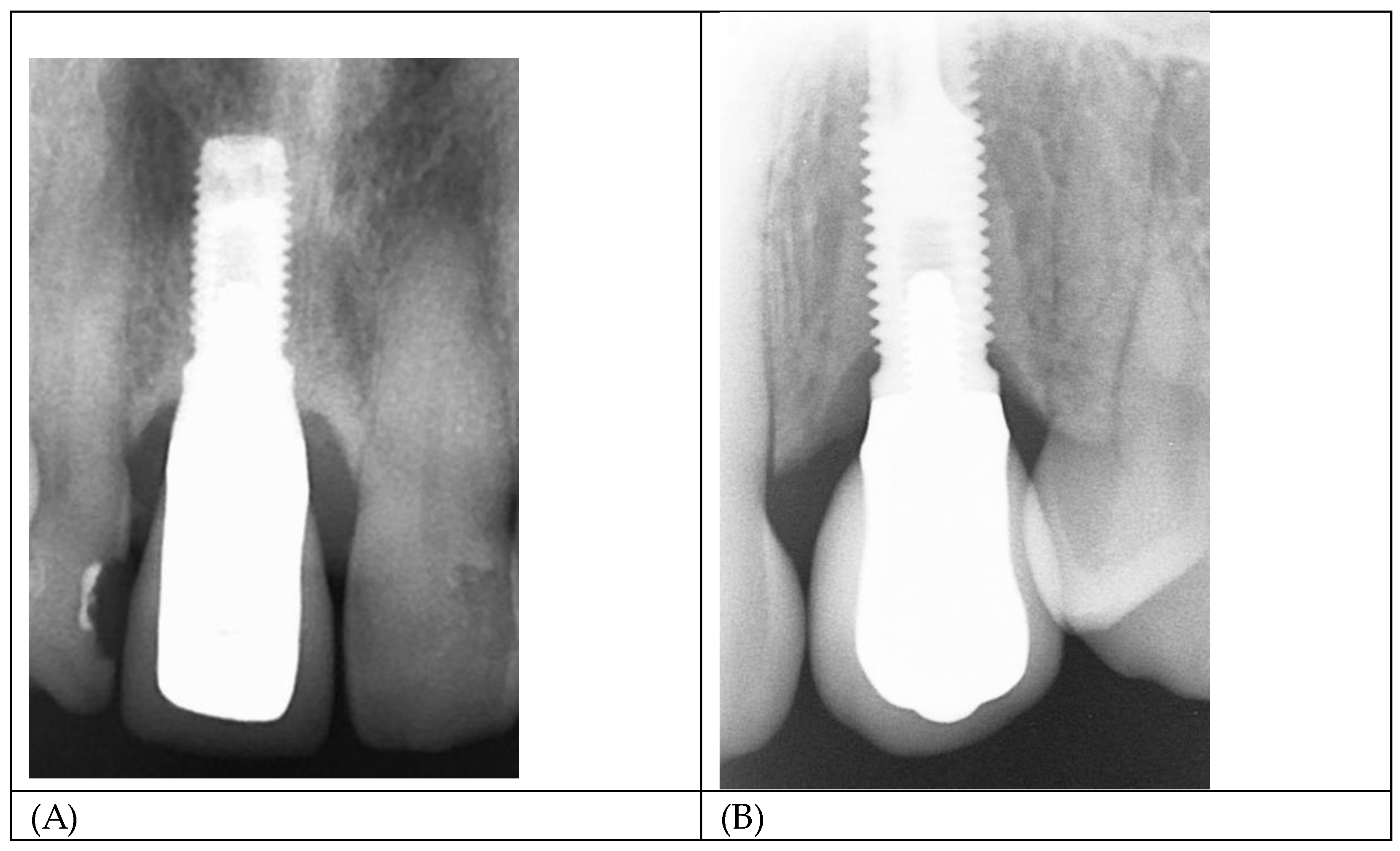
Figure 11 A and B show radiographs of two single implant crowns in-situ for 21years. It could be assumed that the screw seat and/or the implant/abutment interface in A have formed an effective seal against bacterial leakage through the micro-gap but not in B, possibly contributing to marginal bone loss to the first thread.
The use of gold as an abutment material has reduced significantly due to its high cost. Whether it is possible to predictability electrodeposit gold on alternative alloys requires further research. Titanium “TiBase” abutments are commonly used in conjunction with Zirconia prostheses, but Titanium is not conducive to gold electrodeposition. Stainless steel may be an alternative, as stainless steel screws are currently successfully gold plated.
The gold electrodeposit regimen employed was empirically based on previous use with tooth-supported prostheses where aesthetics, rather than any biological advantages, was the motivation for its implementation. The aesthetic advantages of a golden hue have resulted in the marketing of anodised titanium abutments to create a gold lustre. Further research is required to ascertain if a thicker gold plate can create a more predictable seal at the IAC. Preventing the transference of E-coli across the micro-gap does not equate to a complete biological seal as smaller bacteria and bacterial endotoxins may still pass across it.
The micro-gap bacterial leakage test protocol used proved effective in ensuring that any bacterial transfer was confined to the screw/abutment or implant/abutment connections. It can be concluded that it is possible to get an effective micro-gap barrier < 2μm, at the implant/abutment connection, as E.coli have dimensions approximately 0.2 X 2.0μm, in both the castable and cast-to UCLA abutments, with or without gold plating. However, the limited sample size prevents any conclusion regarding differences between the plated and non-plated cast abutments.
Internal abutment connections of various geometrical configurations, have supplanted external hexagon connections in many regions. However, it has been documented that mechanical failures such as abutment and screw fractures are more catastrophic in internal connection systems.[
33] The introduction of bi-axial implants to minimise necessity for grafting procedures has also seen a resurgence of the external hexagon design.
There are limitations to this study. Only one high gold content alloy and only one bacteria type were used. The test assemblies were not dynamically loaded, which may or may not enhance the plastic deformation and seal of the IACs. The limited number of test assemblies prevented a statistical analysis between the plated and non-plated test assemblies.
5. Conclusions
Within the limitations of the study, the following conclusions can be drawn:
1. Abutment connecting surfaces, both Au plated and not Au plated, showed plastic deformation (smearing) in variable mosaic patterns across the micro-gap with the high-gold content alloys used in the study.
2. External micro-gap measurements do not give a true indication of the profiles and approximation of the abutment/implant connecting surfaces.
3. External micro-gap dimensions of cast and pre-machined external hexagon abutments with and without Au plating measured under shadow eliminating silhouette illumination averaged < 3.5 μm.
4. An uninterrupted smeared layer across the abutment fitting surface can provide an effective barrier to egress of bacteria from the internal regions of the implant.
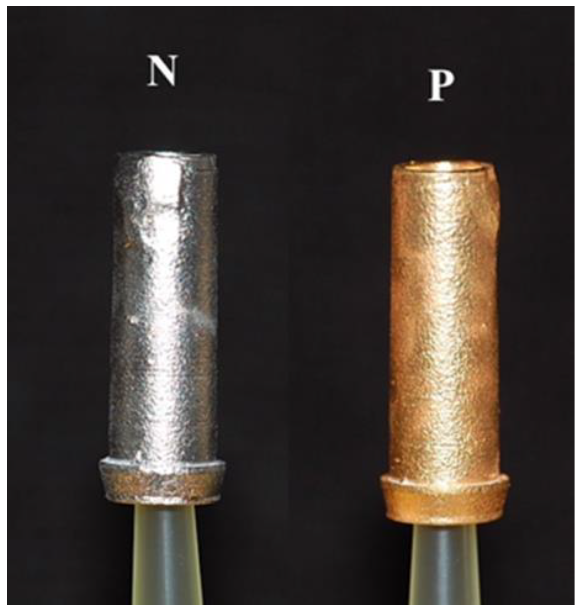
Figure 1.
Samples of the PUCLA abutments (N=non-plated, P=plated).
Figure 1.
Samples of the PUCLA abutments (N=non-plated, P=plated).
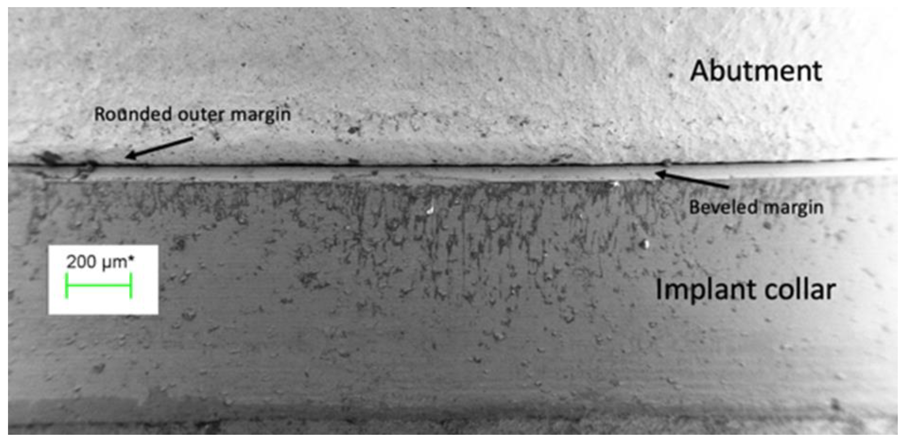
Figure 2.
The external perimeter of the implant/abutment junction at 100 times magnification illustrating the bevelled margin on the implant and the rounded outer edge of the abutment.
Figure 2.
The external perimeter of the implant/abutment junction at 100 times magnification illustrating the bevelled margin on the implant and the rounded outer edge of the abutment.
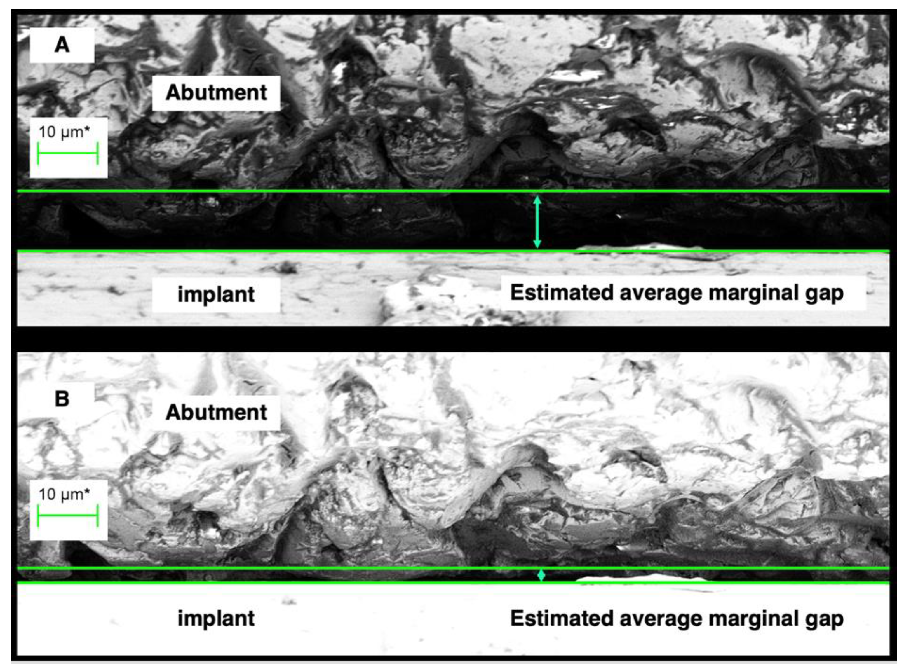
Figure 3.
A region of the external perimeter of a micro-gap at 2000 times magnification. The distance between the green lines - the cursor height, is considered the micro-gap width for the region. (A ) shows assessment under normal illumination while (B) shows assessment of the same region under silhouette illumination. The difference in actual gap width is significant with the measurement at (B) more indicative of actual discrepancy of fit.
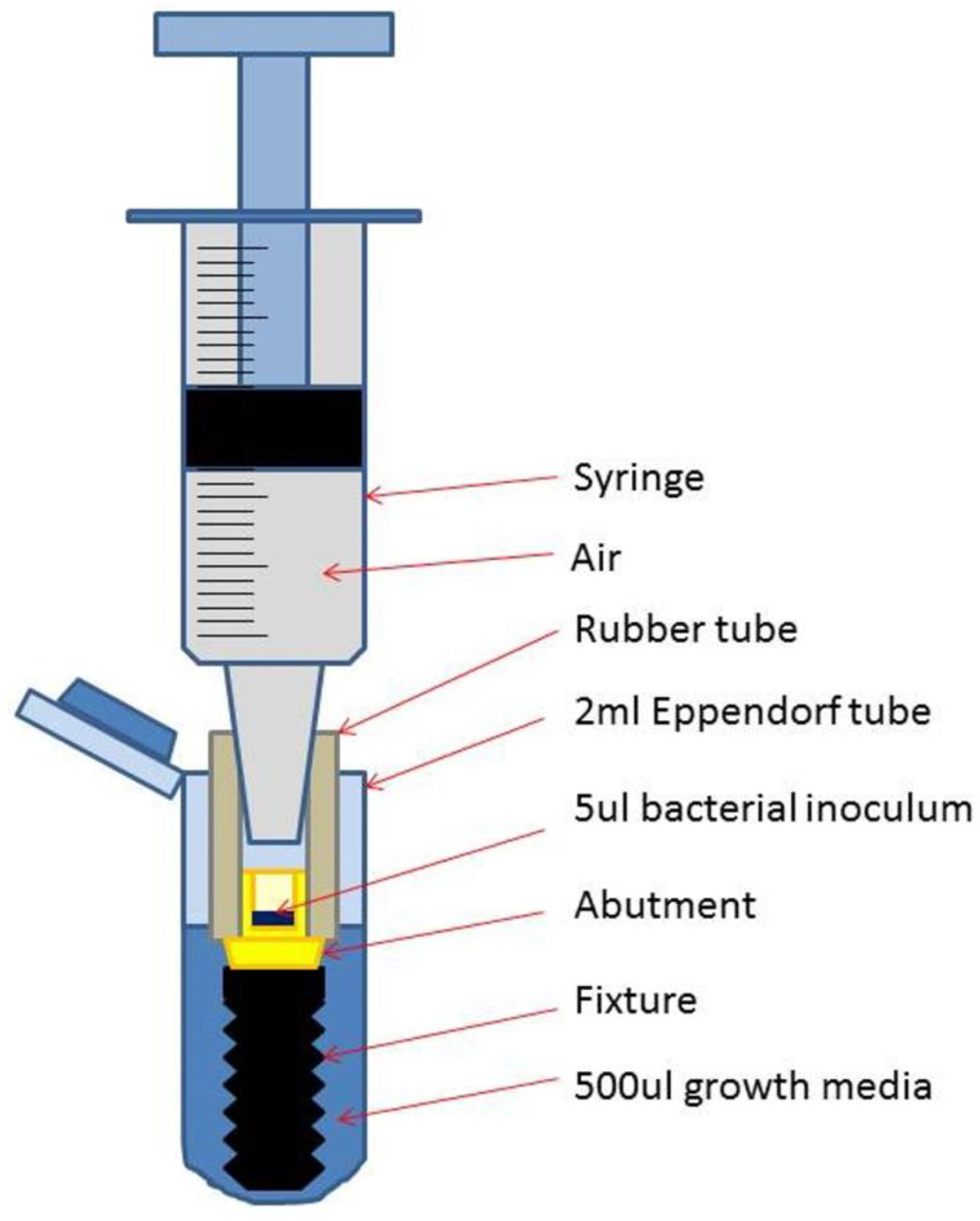
Figure 4.
Schematic drawing of a test assembly (TA) placed in the Eppendorf tube with added growth medium.
Figure 4.
Schematic drawing of a test assembly (TA) placed in the Eppendorf tube with added growth medium.
Figure 5.
Flow chart showing allocation and bacterial leakage of the 21 Tas.
Figure 5.
Flow chart showing allocation and bacterial leakage of the 21 Tas.
Figure 6.
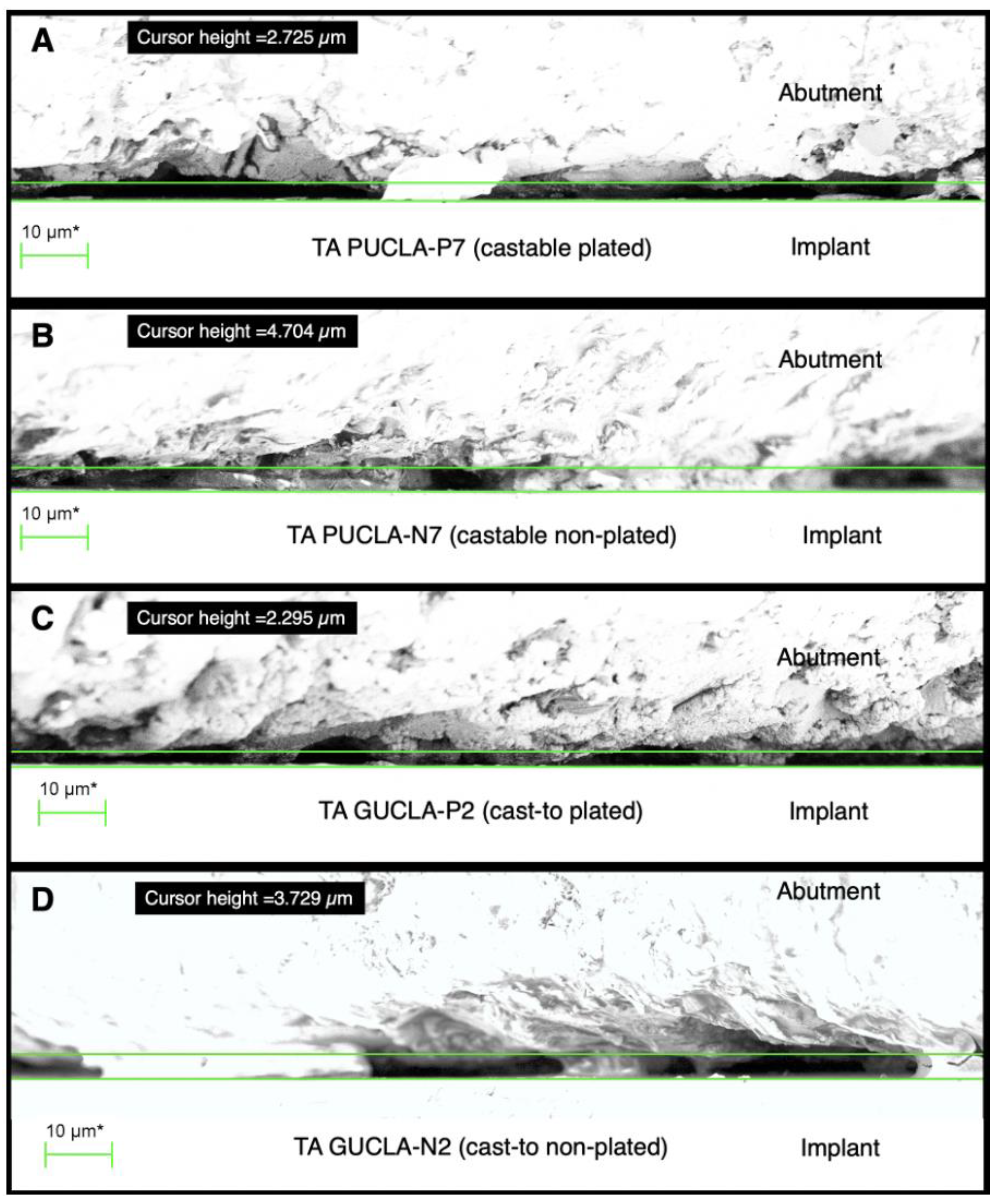
Sections of external perimeter micro-gap profiles for examples of the 4 different TA types: A - PUCLA-P7, B - PUCLA-N7, C - GUCLA-P2, D - GUCLA-N2. Note the surface asperities which are in intimate contact with the implant surface. The average “gap” set by the cursor is < 5 μm for all groups.
Figure 7.
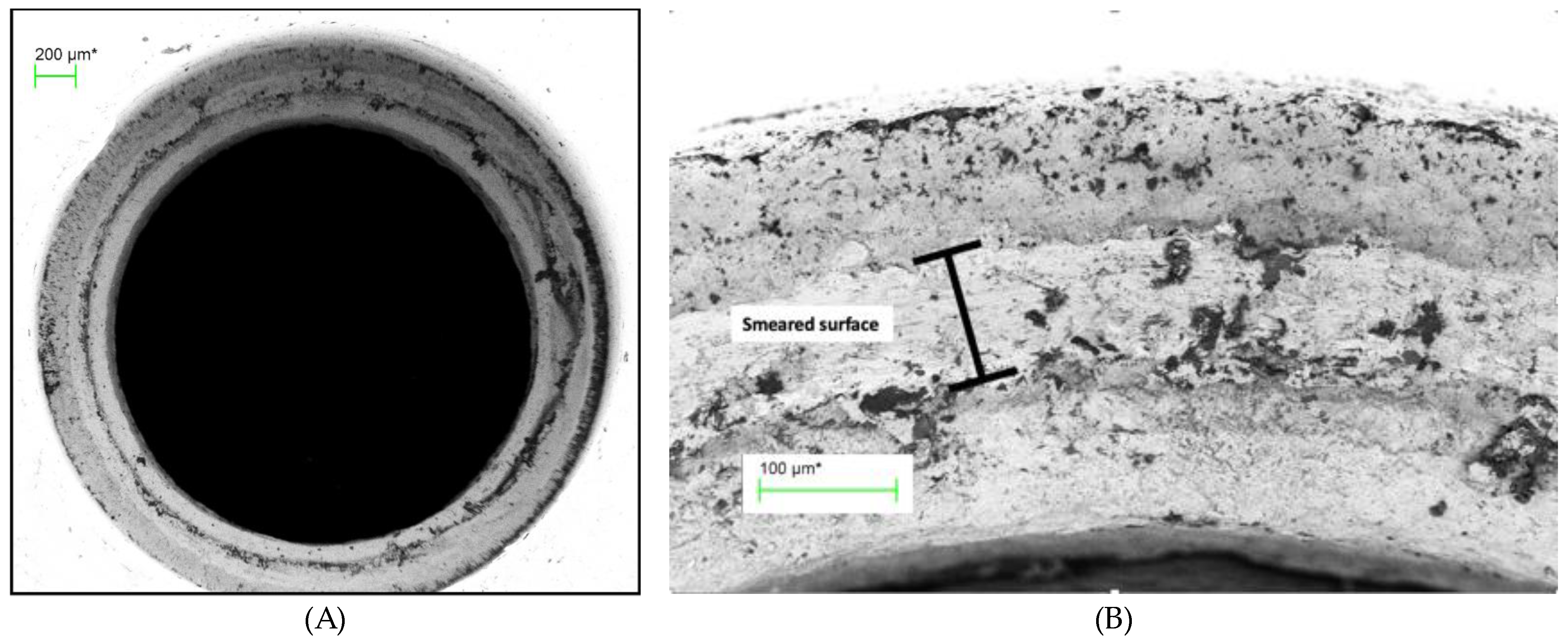
(A) Abutment screw seat of TA PUCLA-N5 (70X), (B) Higher magnification (454X) of a section of the screw seat of the abutment of TA PUCLA-N5.
Figure 7.
(A) Abutment screw seat of TA PUCLA-N5 (70X), (B) Higher magnification (454X) of a section of the screw seat of the abutment of TA PUCLA-N5.
Figure 8.
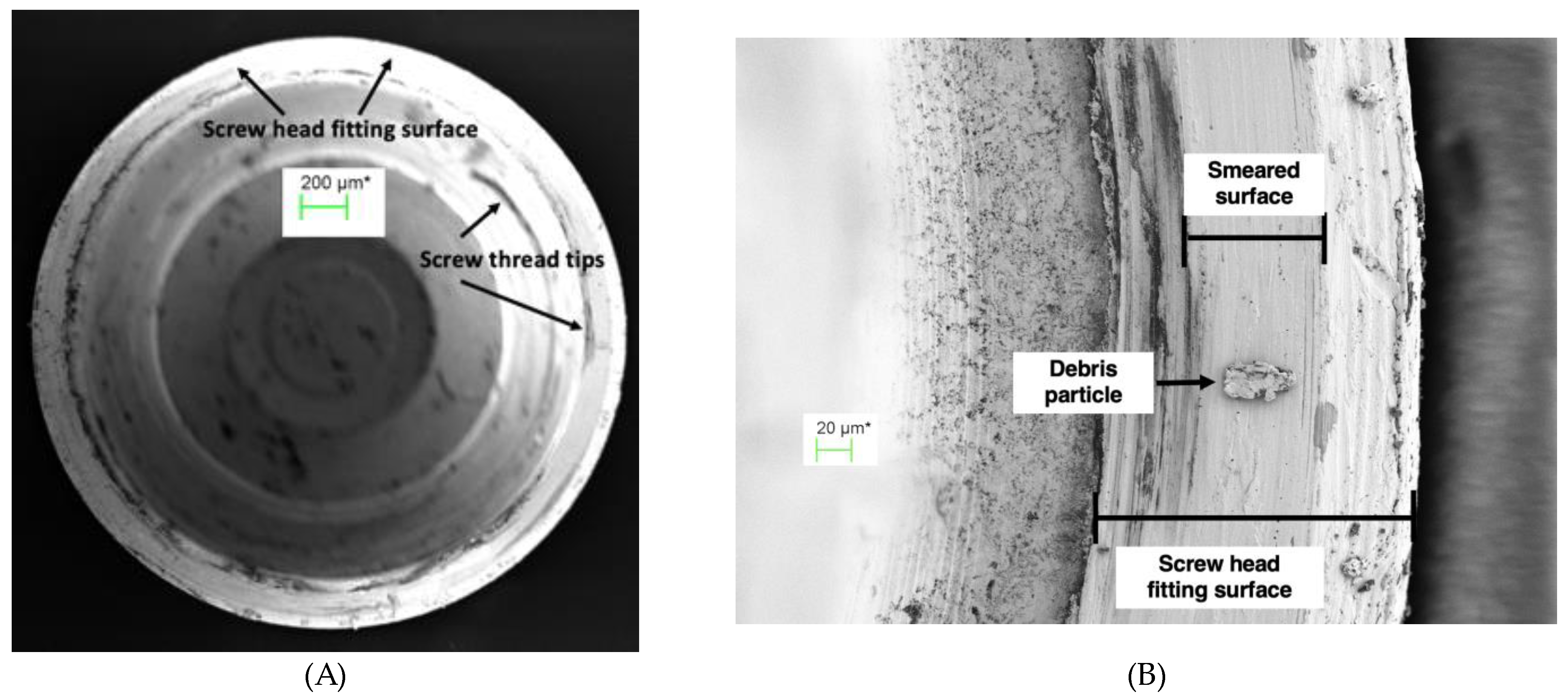
(A) Screw head fitting surface of TA PUCLA-N5 (70X), (B) Higher magnification (563X) of a section of the screw head fitting surface of TA PUCLA-N5 showing a smeared surface which appears continuous.
Figure 8.
(A) Screw head fitting surface of TA PUCLA-N5 (70X), (B) Higher magnification (563X) of a section of the screw head fitting surface of TA PUCLA-N5 showing a smeared surface which appears continuous.
Figure 9.
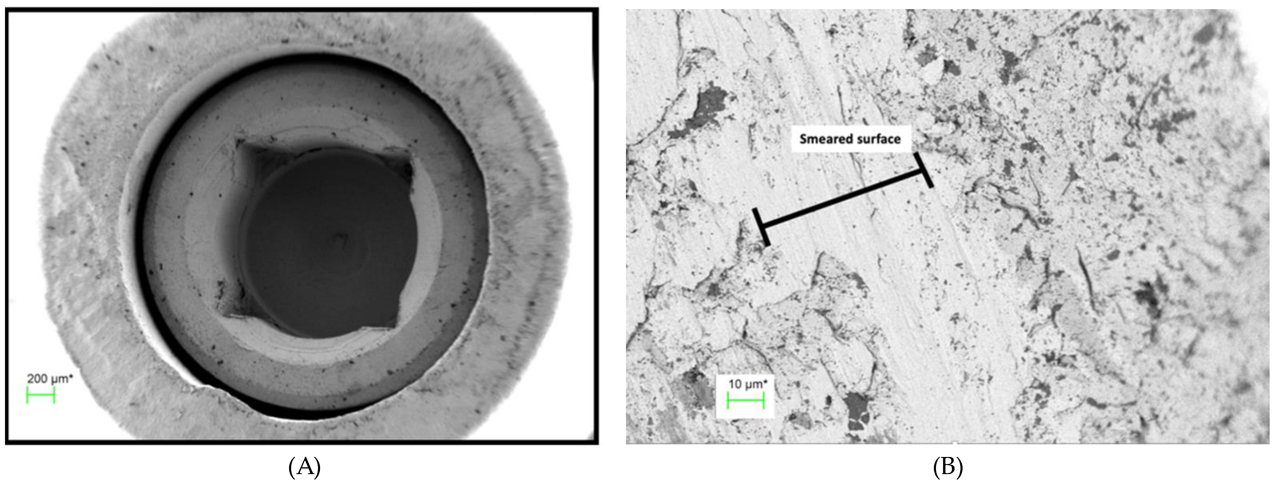
(A) Abutment fitting surface of TA PUCLA-N5 at 60 X magnification showing a region of smeared surface, (B) Higher magnification of abutment fitting surface of TA PUCLA-N5 at 1,580 X magnification showing a region of smeared surface.
Figure 9.
(A) Abutment fitting surface of TA PUCLA-N5 at 60 X magnification showing a region of smeared surface, (B) Higher magnification of abutment fitting surface of TA PUCLA-N5 at 1,580 X magnification showing a region of smeared surface.
Figure 10.
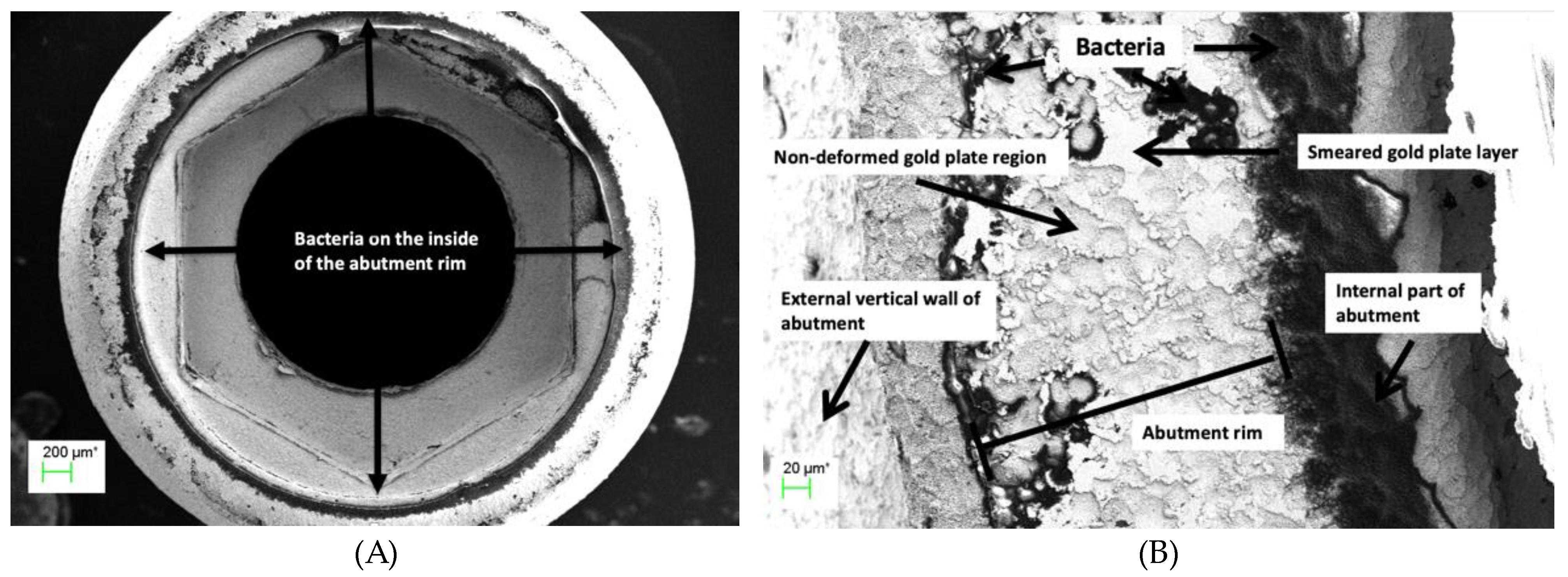
(A) Abutment rim of plated TA PUCLA-P2 at 53X magnification. Bacteria are evident on the internal and external aspects of the abutment fitting surface, (B) Higher magnification (501X) of the abutment fitting surface of plated TA PUCLA-P2. Masses of bacteria are evident on the internal aspect indicating leakage through the screw/thread connection. The smeared region shows a mosaic pattern with discontinuity across the surface with resultant bacteria on the external aspect.
Figure 11.
(A,B) Radiograph of single implant crowns, in-situ for 21 years. In A, there is no radiolucency at the implant/abutment interface, indicative of an effective seal at either the screw/thread or implant/abutment connections. In B the radiolucency extending to the first thread is indicative of a zone of inflammation resulting in loss of MBL and possibly associated with bacterial leakage through the micro-gap.
Table 1.
Composition of the gold alloy – V classic.
Table 1.
Composition of the gold alloy – V classic.
| Element |
composition % |
| Gold - Au |
75 |
| Palladium - Pd |
19 |
| Silver - Ag |
1 |
| Copper - Cu |
0.44 |
| Zinc - Zn |
0.5 |
| Tin - Sn |
2 |
| Indium |
2 |
| Iridium - Ir |
0.01 |
| Ruthenium - Ru |
0.06 |
Table 2.
Measurements of the micro-gaps (MG) (μm) of 4 of the PUCLA-P IACs.
Table 2.
Measurements of the micro-gaps (MG) (μm) of 4 of the PUCLA-P IACs.
| TA |
Description |
MG-1 |
MG-2 |
MG-3 |
Mean MG |
| 1 |
PUCLA-P1 |
3.2 |
3.2 |
2.9 |
3.1 |
| 2 |
PUCLA-P2 |
4.7 |
2.9 |
1.8 |
3.1 |
| 3 |
PUCLA-P3 |
1.7 |
1.4 |
2.5 |
2.5 |
| 4 |
PUCLA-P4 |
1.9 |
1.0 |
1.3 |
1.3 |
Table 3.
Colony-forming unit counts (CFUs) from the bacterial leakage test for the fifteen study TAs that passed the initial sterility test.
Table 3.
Colony-forming unit counts (CFUs) from the bacterial leakage test for the fifteen study TAs that passed the initial sterility test.
| TA |
Media /dilution |
Bubbles |
| |
430 μl |
50 μl |
1:100 |
1:1000 |
1:10000 |
|
| PUCLA-P2 |
~600 |
188 |
40 |
7 |
1 |
No |
| PUCLA-P3 |
~350 |
206 |
17 |
1 |
0 |
No |
| PUCLA-P4 |
~350 |
152 |
24 |
1 |
0 |
No |
| PUCLA-P6 |
0 |
- |
- |
- |
- |
No |
| PUCLA-P7 |
0 |
- |
- |
- |
- |
No |
| |
|
|
|
|
|
|
| PUCLA-N3 |
xxx |
xxx |
295 |
81 |
9 |
No |
| PUCLA-N5 |
0 |
- |
- |
- |
- |
No |
| PUCLA-N6 |
0 |
- |
- |
- |
- |
No |
| PUCLA-N7 |
0 |
- |
- |
- |
- |
No |
| PUCLA-N8 |
xxx |
xxx |
xxx |
~500 |
80 |
Yes |
| |
|
|
|
|
|
|
| GUCLA-N1 |
0 |
- |
- |
- |
- |
No |
| GUCLA-N2 |
0 |
- |
- |
- |
- |
No |
| GUCLA-N3 |
0 |
- |
- |
- |
- |
No |
| |
|
|
|
|
|
|
| GUCLA-P1 |
0 |
- |
- |
- |
- |
No |
| GUCLA-P2 |
0 |
- |
- |
- |
- |
No |
