1. Introduction
The spherical joint is a mechanism that can achieve three rotary degrees of freedom [
1]. It is compact in structure and flexible in motion, and is widely used in parallel mechanisms, machine tools, measuring instruments, medical devices, optical devices, and various other equipment [
2,
3]. As a purely passive component, it is unable to determine its rotation orientation and angle [
4]. If an embedded precise measurement method for its rotation angle can be found, the spherical joint will become an intelligent device with broader application prospects, which is beneficial for improving the motion accuracy and facilitating control of equipment which the spherical joints are employed in. [
5,
6]
Over the past several decades, the identification of spherical rotation direction and angle measurement techniques have been researched and developed. Several measurement methods based on different principles have emerged, mainly include optical [
7,
8], magnetic field [
9], and inertial field [
10,
11]. For example, Min Li from Minnesota State University, USA, utilized embedded sensors to simultaneously measure the magnetic flux density and back electromotive force of a spherical motor. The data from these sensors were input into a sensor fusion system based on Kalman filtering to estimate the three degrees of freedom of angular displacement and angle in real-time. Experimental results showed that within a certain measurement range, the average measurement error of the system in a single axis was 0.08° [
12]. Korean scholars, Jae-Hyeok Kim et al. proposed using a precision mechanical sensor called Attitude and Heading Reference System (AHRS), comprising of a gyroscope, accelerometer, and magnetometer, to measure the tilt angle of a spherical motor [
13]. The measurement accuracy of the two axes was 0.27° and 0.83° respectively, but this method cannot measure the self-rotation angle of the motor, and the accuracy still needs improvement. Wang et al. team also proposed a sensorless rotor attitude detection method based on the mutual inductance voltage of the stator coil. In the online detection process of rotor position, the three-dimensional position angle of the rotor is inversely calculated based on the real-time collected mutual inductance voltage information, using an intelligent optimization algorithm, combined with the distribution law of mutual inductance voltage and the constraints of the rotor structure. This detection method has a good online detection effect, with a standard deviation of the group within 1.8° [
14], but the accuracy is not high. S. Yang et al. from the Chinese Academy of Sciences proposed a 2-degree-of-freedom angle displacement measurement method using a spherical capacitive sensor to measure the spherical pair [
15]. The capacitance sensor proposed in this method has a four-quadrant differential electrode configuration. Compared with other angle measurement detection methods, it has an integrated structure, occupies a small space, and is convenient to integrate into the sphere. However, this method is unable to achieve measurements around the rotation axis.
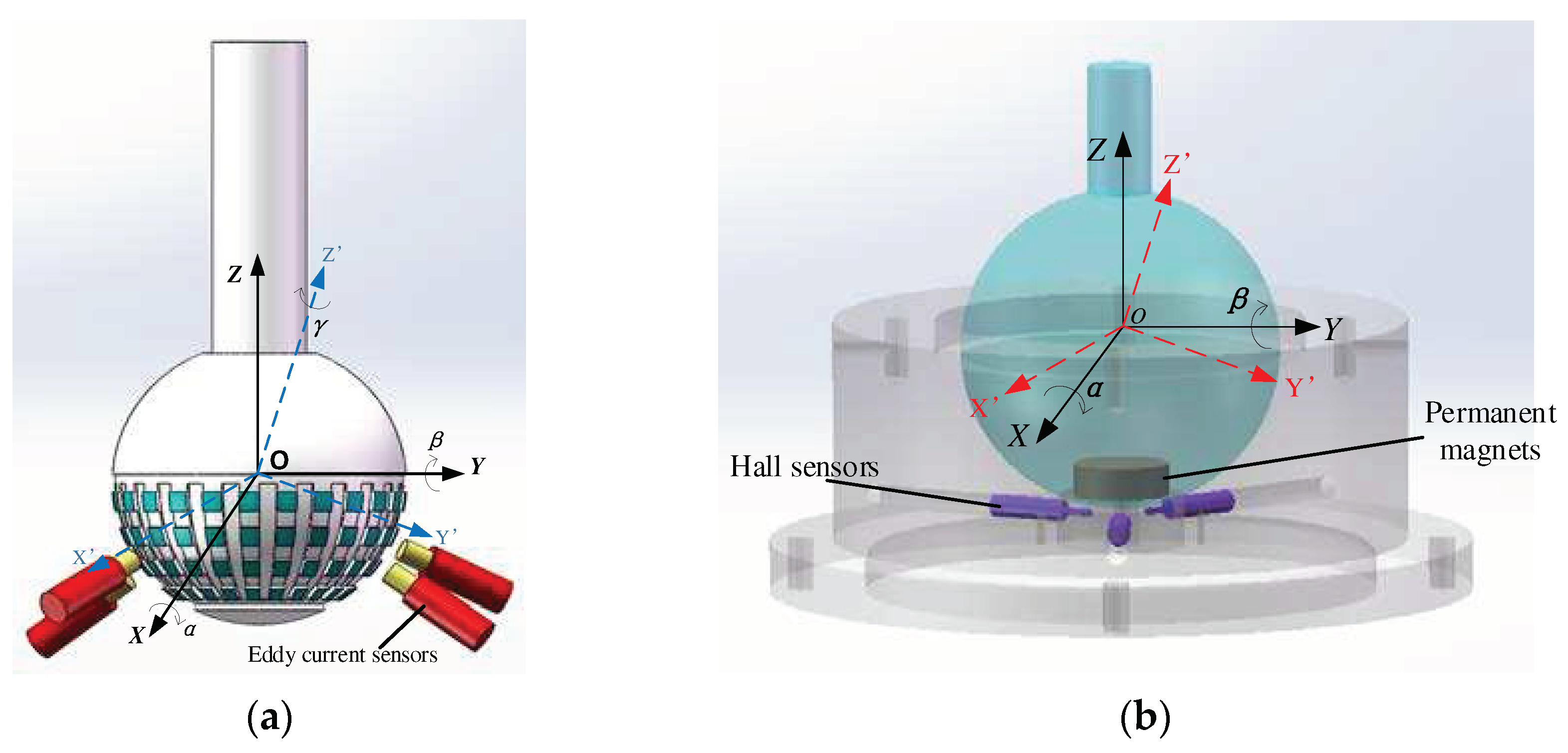
Under the support of the National Natural Science Foundation of China, our team has proposed a measurement scheme for three-dimensional rotational angles in the spherical joint space based on eddy current sensors and pseudo-random coding. As shown in
Fig.1(a), a sensor array is formed by multiple sensors to recognize the spherical coding. An artificial neural network is employed to establish a measurement model between the output voltage of the eddy current sensors and the spatial three-dimensional(3D) rotational angles. Consequently, the measurement of 3D rotational angles in the spherical joint space is realized [
16,
17]. In this scheme, the pitch angle α and the twist angle β are within the range of -10° to 10°, with root mean square errors of 22’32" and 25’58", respectively. The rotational angle γ of the spherical joint along the axis of the spherical joint rod is within the range of 0° to 120°, with a root mean square error of 30’17".
Figure.1(b) presents another scheme proposed by our team for measuring the 2D rotational angle of the ball hinge. In this scheme, a cylindrical permanent magnet is embedded in the bottom of the ball head, and a Hall sensor installed in the ball socket is used to measure the rotational angle of the ball head in any direction in space. Finally, the measurement value is decomposed into the rotational angle components α and β around the X and Y axes. The maximum accuracy of single-axis angle measurement in this scheme can reach 4′ [
18].
The accuracy level of the measurement scheme based on eddy current sensors and pseudo-random coding of the three-dimensional slewing angle in spherical joint space is not yet able to meet the needs of the precision engineering field. So in this paper, based on the magnetic effect method and spherical coding method researched by the group in the previous period, we combine the advantages of the two method to construct a new combined measurement scheme.
2. Measurement Plan Design
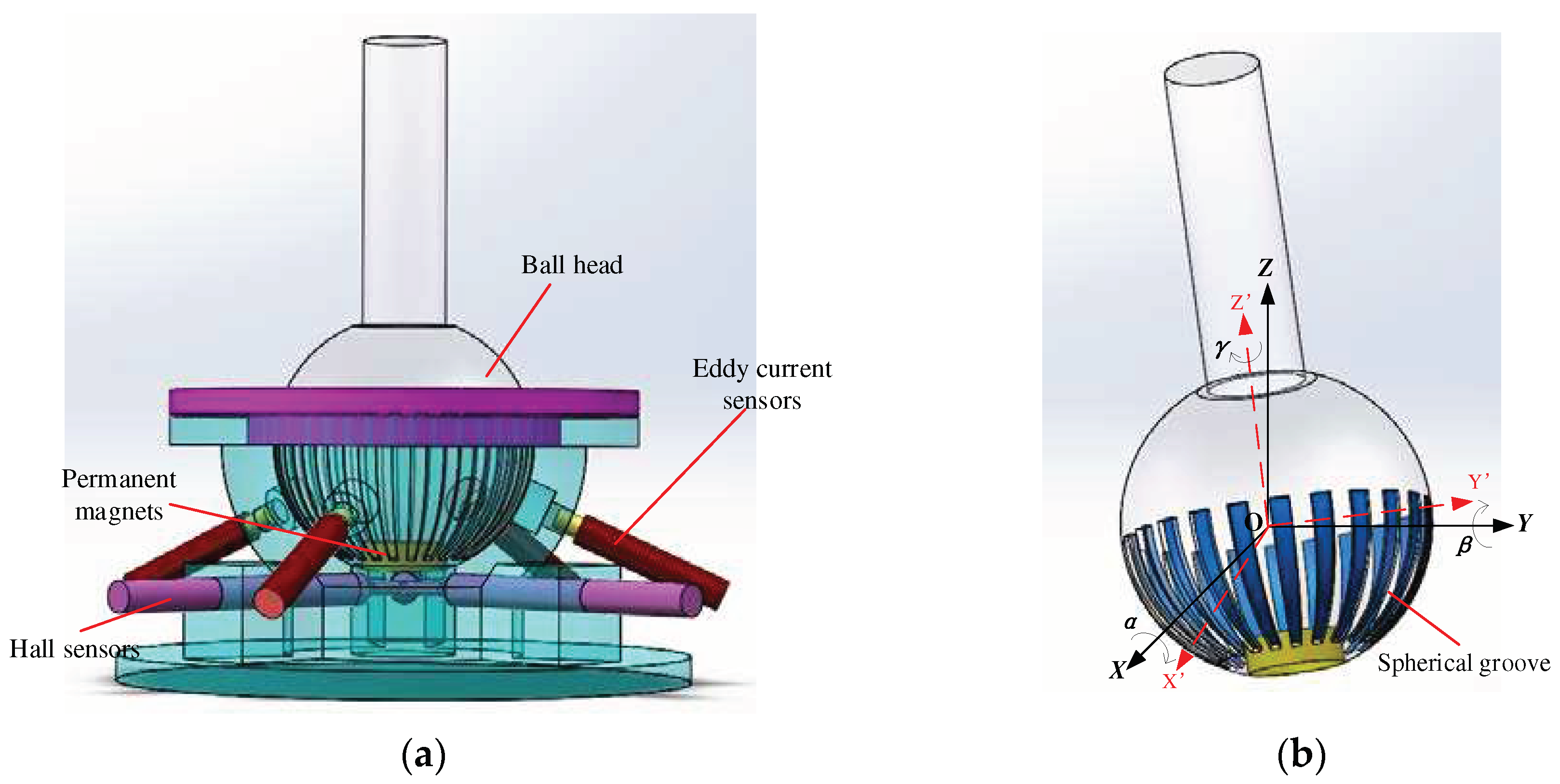
This scheme embeds a permanent magnet into the bottom of the ball head and uses three Hall sensors to detect the magnetism of the ball head. When the spherical joint rotates, the Hall sensors perceive the 3D rotation angle of the ball hinge through the change in the magnetic field. However, this scheme has low measurement accuracy for the roll angle γ. Therefore, a one-dimensional groove is machined on the surface of the metal ball head to improve the measurement accuracy of the self-rotation angle γ using the distance measuring principle of eddy current sensors, and also to enhance the measurement accuracy of the pitch angle α and the yaw angle β. The overall design is shown in
Figure 2.
2.1. Sensor Placement Location
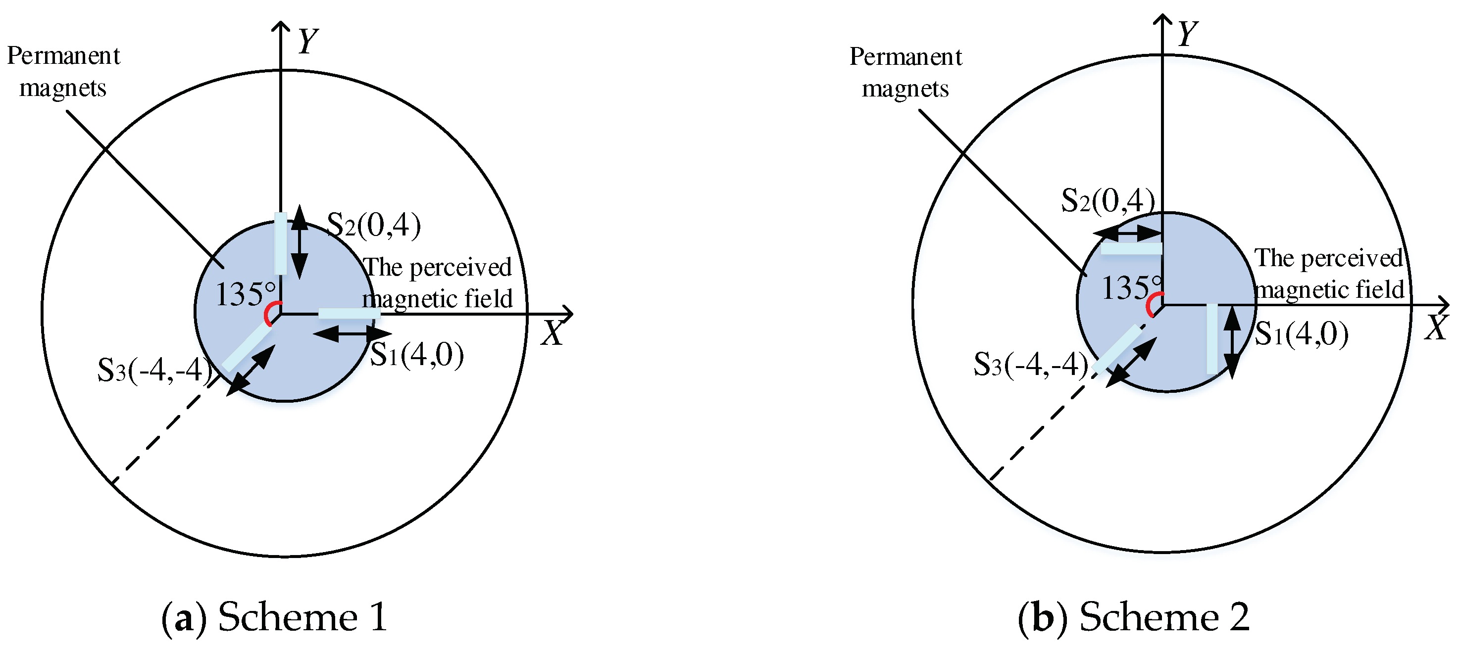
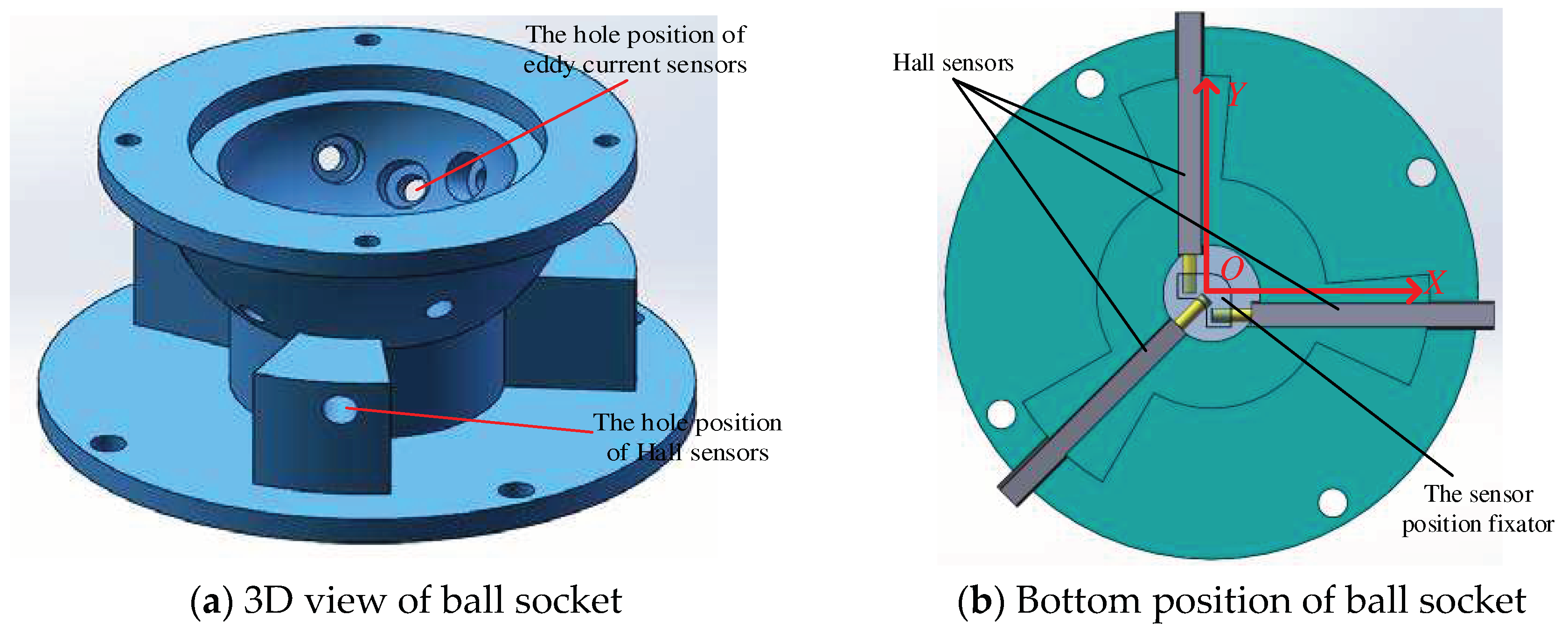
Place three Hall sensors horizontally into the bottom of the ball socket. Use the sensor position fixator inside the ball socket to secure the three Hall sensors in the same plane. Two different sensor placement schemes are used here for comparison. Scheme 1: as shown in
Fig.3(a), sensor S1 is located on the X-axis and senses the magnetic field in the X-axis direction, sensor S2 is located on the Y-axis and senses the magnetic field in the Y-axis direction, and sensor S3 is located on the axis that is 135°counterclockwise from the Y-axis, sensing the magnetic field in the axial direction. Scheme 2: as shown in
Figure.3(b), rotate sensors S1 and S2 by 90°respectively. S1 measures the magnetic field component in the Y-axis direction, and S2 measures the magnetic field component in the X-axis direction. The position of S3 remains unchanged.
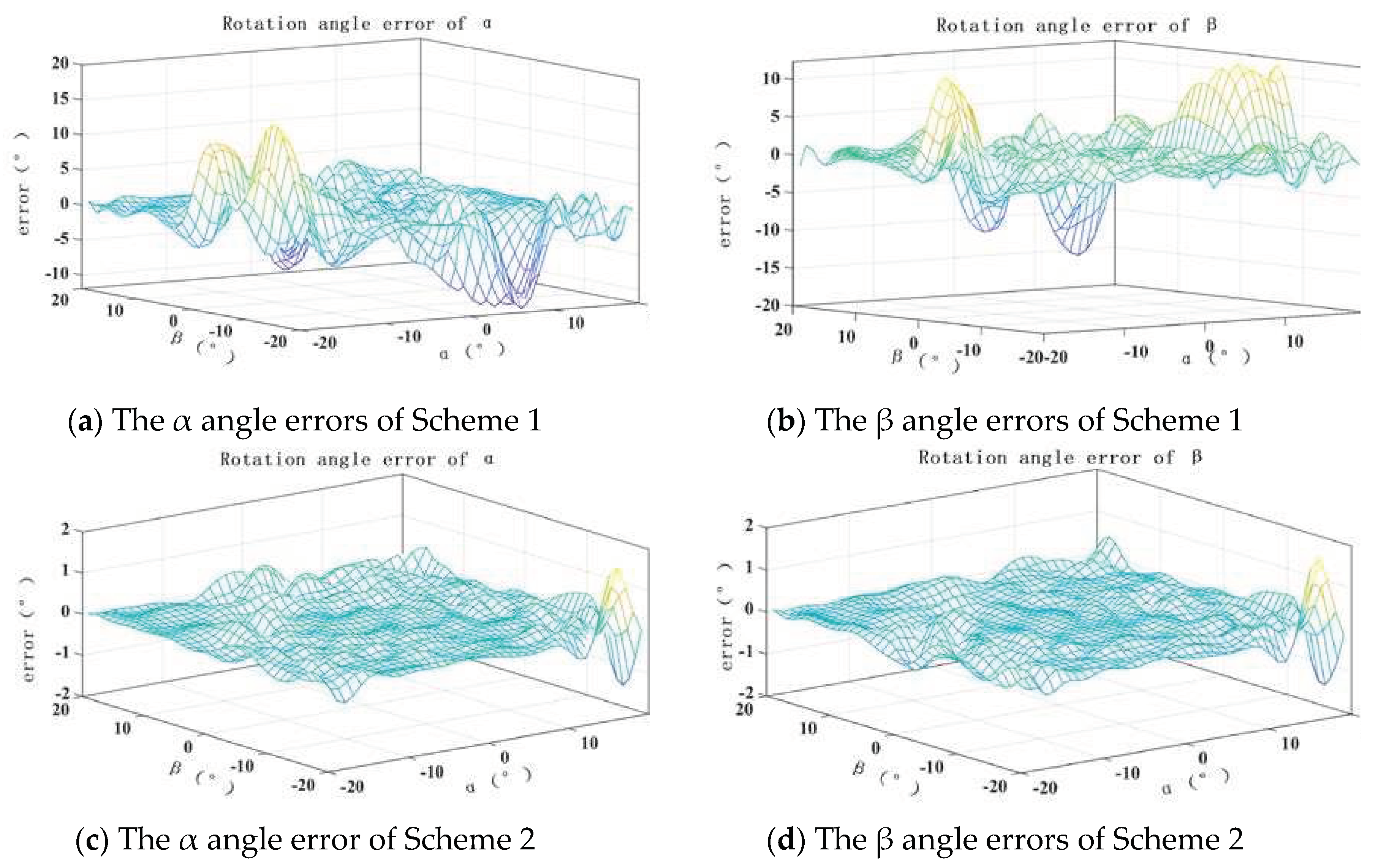
The simulation of the two schemes using COMSOL and MATLAB, the error results of α and β angles after fitting with RBF neural network are shown in
Figure.4. It can be seen that scheme 2 has higher measurement accuracy for α and β angles, so scheme 2 is adapted to place the Hall sensor. The design of the ball socket is shown in
Figure.5. Based on the previously described spherical coding scheme, it is of positive significance to improve the accuracy of measuring the three-dimensional rotation angle of the spherical joint by arbitrarily selecting four asymmetric positions for installing the eddy current sensor on the spherical socket surface.
2.2. Spherical groove design
Using the AD/DC module of the COMSOL physics field simulation tool, a 3D finite element model was established. By simulating and analyzing grooves with different parameters on a metal block, the parameter settings of the grooves on the surface of the spherical head were determined. Based on the previous research results of our team on the output characteristics of eddy current sensors [
19], it is known that the inductance of the sensor will undergo significant changes when scanning grooves with different parameters, especially when the sensor is located at the center of the groove, the difference value is maximum. For grooves with the same width, the larger the groove depth, the greater the change in inductance; for grooves with the same depth, the larger the groove width, the greater the change in inductance. Additionally, the sensor is more sensitive to groove depth than groove width.
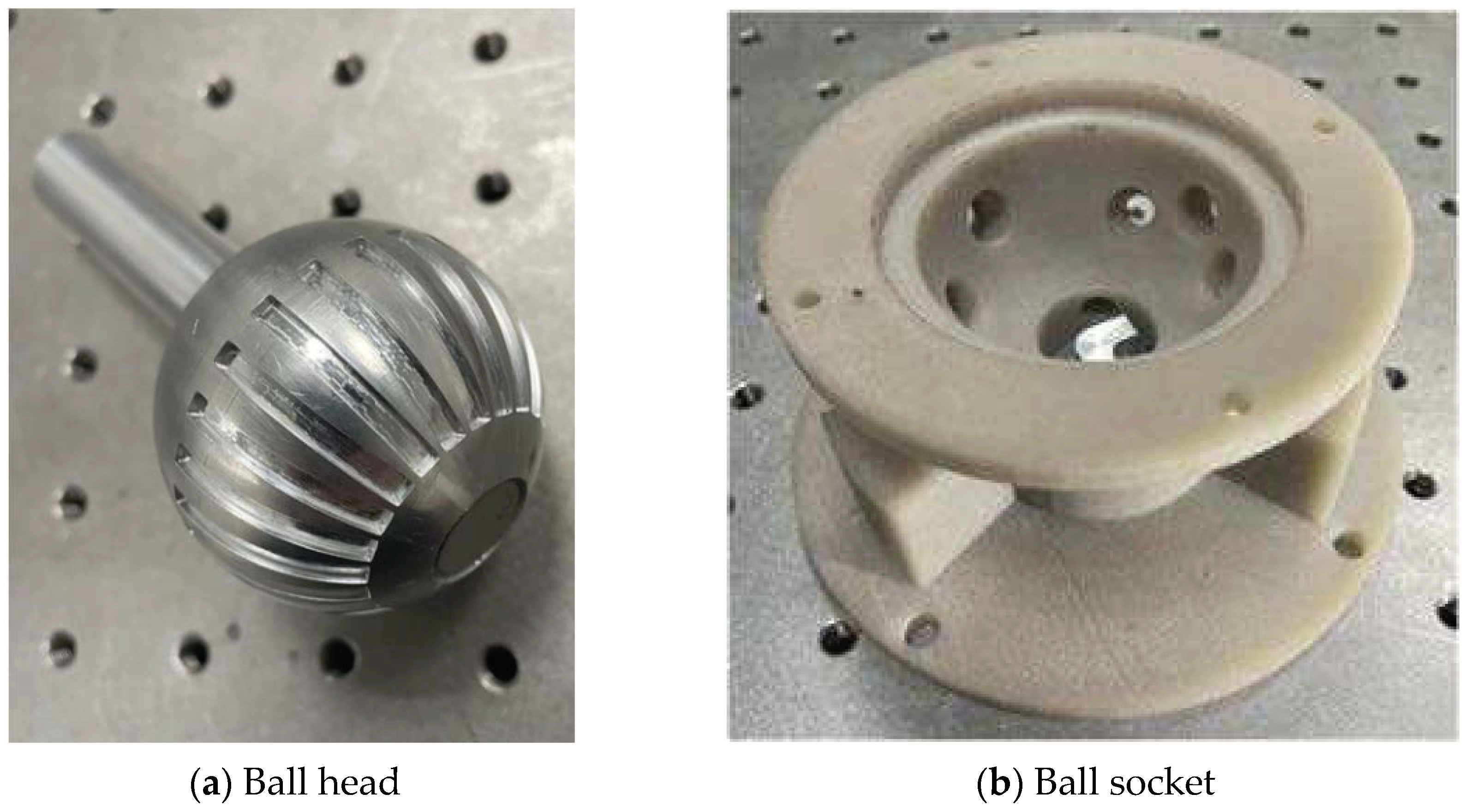
Therefore, in this study, only the parameter setting of groove depth is modified. Finally, through a large number of combination schemes, the optimal solution is determined as follows: the spherical head is divided into 24 groups, with each group consisting of a 15° interval, and the groove width occupies 7°l (where l is the arc length when the central angle of the equatorial plane of the sphere is 1°). Among these groups, 12 groups have groove depths starting from 0.1mm and increasing by 0.1mm each time, while the other 12 groups have groove depths starting from 1.25mm and decreasing by 0.1mm each time. Based on the design scheme described above, The physical structures of the ball head and the ball socket are shown in
Fig.6. The ball head is made of aluminum alloy, and the ball socket is manufactured using 3D printing with nylon material, which does not affect sensor measurements.
3. RBF Neural Network
Based on the team’s previous experience of using neural network modeling [
20,
21], establishing a measurement model for the rotational angle of the spherical joint space based on artificial neural networks can simplify the algorithm model, eliminate the complex and lengthy model derivation process, and the high robustness of the neural network can also compensate for the defects in prototype structural parameters, installation errors, and gap errors during ball head movement. Among them, the RBF neural network can approximate any nonlinear function with arbitrary precision and has good generalization ability. When the network parameters are determined, the output of the network is the linear weighted sum of the hidden layer node outputs, so various linear optimization algorithms can be used to solve the network weights, speed up the learning speed, and avoid local minimum value problems [
22].
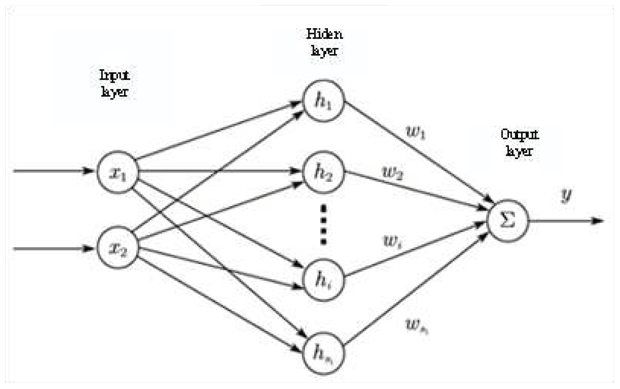
The RBF neural network structure, as shown in
Fig.7, is composed of the input layer, hidden layer, and output layer. The transformation from the input layer space to the hidden layer space is non-linear, while the transformation from the hidden layer space to the output layer space is linear.
The network input is the output of the Hall sensor and the eddy current sensor, denoted as X= [x1, x2, …, x7] T. The network output is the predicted values of three rotational angles, denoted as Y= [ y1, y2, y3] T. The expression of the output layer of the RBF network is:
where ω is the output weight vector,
is the number of nodes in the hidden layer;
is the activation function, and the Gaussian function is the most commonly used radial basis function;
represents the center parameter of the kernel function for the
hidden layer neuron, while
is the expansion constant for the
hidden node.
Due to the fact that the center points selection of the RBF algorithm uses the K-means algorithm, the training process adjusts the weights of the network using either gradient descent or least squares method, which often leads to overfitting and reduces the model’s generalization ability. While the RBF neural network optimizes the centers of the hidden layer, expansion constants, and output weights as particles in the particle swarm algorithm, this approach effectively avoids overfitting and other problems that may arise during model training [
23]. Therefore, this paper uses the PSO algorithm to optimize the RBF neural network, improve its robustness and generalization ability, and enhance the accuracy of the measurement system.
The optimization goal of the PSO algorithm is to minimize the error function value between the actual output and the expected output of the RBF neural network. The fitness function is set as the objective:
where,
N represents the number of samples, n represents the number of outputs of the neural network,
represents the
expected output of the
sample of the RBF neural network, and
represents the
actual output of the
sample of the RBF neural network.
4. Experiment
4.1. Experimental Equipment
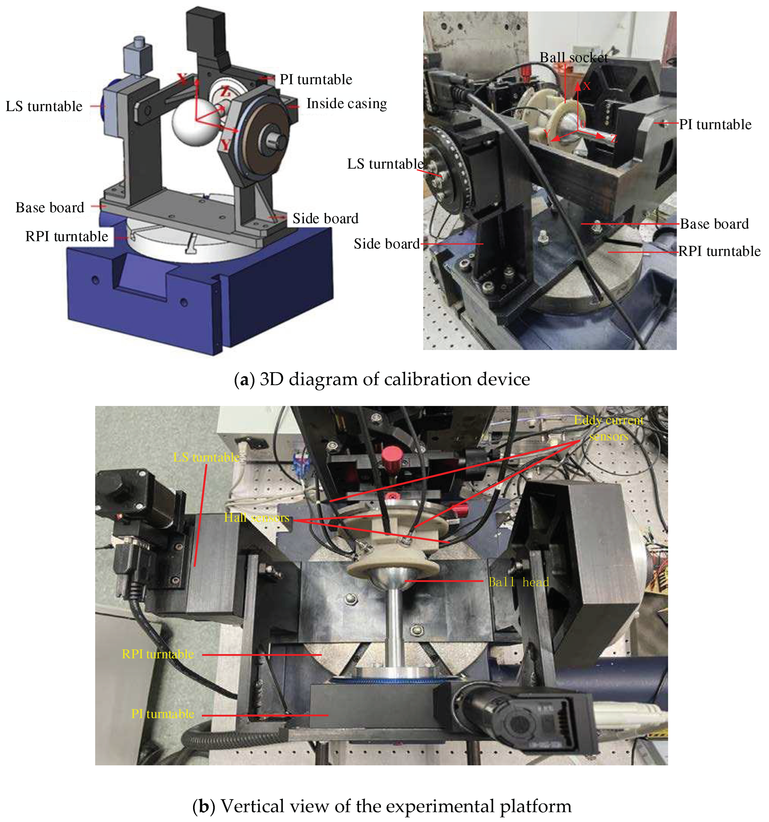
The three-dimensional diagram of the experimental setup, as shown in
Fig.8, includes three calibrated rotary stages for rotation around the X, Y, and Z axes, namely the RPI, LS, and PI stages, with respective accuracies of ±1″, ±4″, and ±2″. The ball head is made of aluminum alloy material with a diameter of 50mm. The permanent magnet used is a cylindrical sintered neodymium iron boron magnet, with a residual magnetic parameter of 1.2mT and magnetization direction along the axis, with a diameter of 15mm and height of 5mm. The Hall sensor has a measurement range of 0~3T and a resolution of 10-5mT. The eddy current sensor has a measurement range of 1.5mm and a resolution of 0.15um.
4.2. Experimental Data Analysis
21*21*181 sets of data were collected in the experiment, with a measurement range of "-10°≤" α≤10° ,"-10°≤" β≤10°,"-90°≤" γ≤90°,and a sampling interval of 1°. Due to the amount of data, inputting all the data into the network resulted in excessively long training time, so the data was partitioned. Based on γ, each 20° was taken as an independent region, with a total of 9 regions.
Table 1 shows the test results for each region, ME represents mean error, and RMSE represents root mean square error. it can be seen that the results between regions are not significantly different.
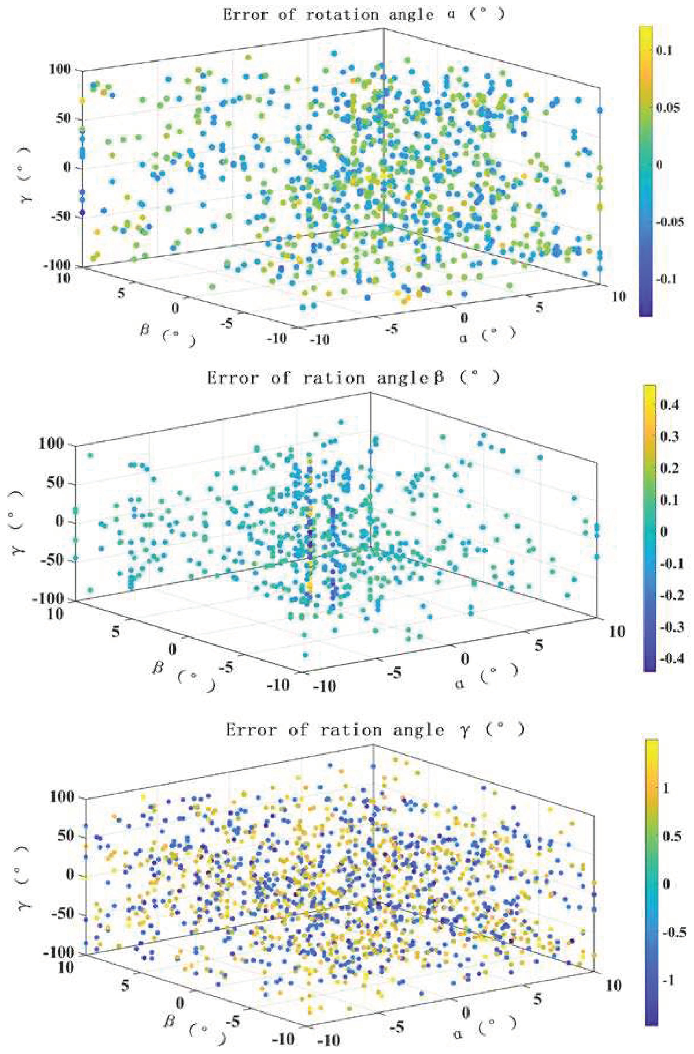
By integrating the measurement results from nine regions, the RMSE of the rotation angles α, β, and γ are found to be 1′8″, 2′15″, and 29′6″, respectively. The test results of all regions are shown in
Fig.9, where the color represents the magnitude of the error. Due to the large number of test points, only points with significant errors are retained in this figure.
5. Analysis of Uncertainty
From the perspective of research progress and experimental experience, the main error factors affecting the measurement accuracy of the three-dimensional rotation of the spherical joint include the error of the permanent magnet structure parameters and magnetic field eccentricity, the eccentricity error of the ball head, the rotational error of the turntable, the error of repeated measurements, the stability error of the sensor, and the fitting calculation error of the neural network model [
24]. Based on these sources of error, it can be understood that several types of uncertainty sources can currently be observed and verified through calculations.
5.1. Uncertainty Introduced by Sensor MEASUREMENT repeatability
Under the same experimental conditions, measurements were repeated 10 times at the same spherical position (5°, 5°, 5°). Based on the results of the 10 repeated measurements, the uncertainty components introduced by the measurement repeatability error were evaluated, as shown in
Table 2.
Standard uncertainty calculation formula for repetitive errors:
where
is the respective angular values for the
measurement, and
is the average value of the angles. The calculation results are shown in
Table 3.
5.2. Uncertainty Introduced by Drift
With the continuous changes in the experimental environment (temperature, vibration, etc.), the measurement system experiences drift in the parameters of its components or mechanisms during operation, which affects the accuracy of the measurement results. To assess the uncertainty introduced by drift in the system, the measurement system is kept stationary in a constant temperature laboratory for a while, and the system’s output values are recorded in real-time. The uncertainty is then evaluated by calculating the range difference of the drift data during this period.
Under the assumption that the drift error follows a uniform distribution, the formula for calculating the standard uncertainty is as follows:
where a is the maximum value of the error of the measured value. The probability that the measurement error falls within the interval (
) is 1. The calculation and results are shown in
Table 4.
Due to the fact that the two uncertainties are caused by different errors, it can be considered that they are independent of each other. Therefore, the formula for the combined standard uncertainty is:
The synthesis freedom is:
The combined uncertainty results are shown in
Table 5.
Take the confidence probability P=0.95, determine the inclusion factor k by checking the t-distribution table through the degrees of freedom, and calculate the spreading uncertainty, the results are:
6. Conclusion
This article presents a new method for precise measurement of 3D rotation angles of spherical joint based on Hall sensors and Eddy current sensors. The spatial position matching of the permanent magnet and Hall sensor is optimized. The relationship between the output of the eddy current sensor and groove parameters is explored to determine the appropriate groove scheme for the ball head. A measurement model is established using the PSO-RBF neural network algorithm, and the feasibility of the method is verified through experiments. The three-dimensional rotation angles of the spherical joint are measured, with the root mean square errors of rotation angles α, β, and γ being 1′8″, 2′15″, and 29′6″, respectively, and the mean errors being 51″, 1′20″, and 22′57″. Compared with the spherical encoding three-dimensional rotation angle measurement scheme with root mean square errors of 22′32″, 25′58″, and 30′17″, the accuracy has been significantly improved.
Author Contributions
Conceptualization, K.O.; methodology, L.Y.; software, Q.Y.; validation, K.O., L.Y. and R.F.; formal analysis, P.H.; investigation, R.F.; resources, P.H.; data curation, L.Y.; writing—original draft preparation, Q.Y.; writing—review and editing, P.H.; visualization, Q.Y.; supervision, K.O.; project administration, K.O.; funding acquisition, Y.Y. All authors have read and agreed to the published version of the manuscript.
Funding
This research was funded by National Natural Science Foundation of China, grant number 52175505.
Institutional Review Board Statement
Not applicable.
Data Availability Statement
Not applicable.
Conflicts of Interest
The authors declare no conflict of interest.
References
- Matteo-claudio, Palpacelli, Luca, et al. Details on the Design of a Lockable Spherical Joint for Robotic Applications. Journal of Intelligent & Robotic Systems, 2016, 81(2):169-179. [CrossRef]
- Gao X, Zhang S, Deng J, et al. Development of a Small Two-Dimensional Robotic Spherical Joint Using a Bonded-Type Piezoelectric Actuator. IEEE Transactions on Industrial Electronics, 2021, 68(1):724-733. [CrossRef]
- Folgheraiter M, Yessirkepov S, Yessaly A. An Actuated Spherical Joint for Humanoid Robotics Applications[C]. IEEE International Conference on Cybernetics and Intelligent Systems; IEEE Conference on Robotics, Automation and Mechatronics. IEEE, 2019.
- Huitaek Yun, Heungki Jeon, et al. Calibration of Industrial Robots with Spherical Joint using Single Wire Encoder. Manufacturing Letters, 2022, 33:46-50. [CrossRef]
- Samuel, E, Wright, et al. The Spherical-Actuator-Magnet Manipulator: A Permanent-Magnet Robotic End-Effector. IEEE Transactions on Robotics, 2017, 33(5):1013-1024. [CrossRef]
- Sb A, Xi A, Ja B. A review of spherical motion generation using either spherical parallel manipulators or spherical motors. Mechanism and Machine Theory, 2019, 140(3):377-388. [CrossRef]
- Li Z, Zhu Y, et al. Position Detection Method of Piezoelectric Driven Spherical Motor Based on Laser Detection. Micromachines, 2022, 13(5):662. [CrossRef]
- Wu T, Guo X, Wang Q, et al. Real-time attitude detection method of permanent magnet spherical motor based on optical sensor . Sensors and Microsystems, 2021, 40(6): 5.
- Gofuku A, Yokomitsu N, Yano T, et al. A Rotor Posture Measurement System by Analyzing Sensed Magnetic Field from Arrayed Hall Sensors[C]// 2019 12th International Symposium on Linear Drives for Industry Applications (LDIA). IEEE, 2019.
- Rong, Yiping, Wang, et al. Improving attitude detection performance for spherical motors using a MEMS inertial measurement sensor. IET Electric Power Applications, 2019, 25(5):1-7. [CrossRef]
- Dai W, Zhang C, Mao Y, et al. A transfer alignment method for inertial attitude correction of spherical motor on moving base. Measurement Science and Technology, 2021, 32(10):105023. [CrossRef]
- M. Li, K. -M. Lee, et al. Sensor Fusion Based on Embedded Measurements for Real-Time Three-DOF Orientation Motion Estimation of a Weight-Compensated Spherical Motor. IEEE Transactions on Instrumentation and Measurement, 2022, 71(35):1-9. [CrossRef]
- Jae-Hyeok Kim, Mi-Jeong Kim, et al. A Study on AHRS Position Sensing Accuracy for Control of the Traction Spherical Motor. The Transactions of the Korean Institute of Electrical Engineers, 2020, 69(4): 225-228. [CrossRef]
- Xu J, Wang Q, et al. Sensorless Posture Detection of Reluctance Spherical Motor Based on Mutual Inductance Voltage. Applied Sciences, 2021, 11(8):3515. [CrossRef]
- Yang S, Xu Y, et al. A Novel Method for Detecting the Two-Degrees-of-Freedom Angular Displacement of a Spherical Pair, Based on a Capacitive Sensor. Sensors. 2022, 22(9):3437. [CrossRef]
- Hu P, Zhao L, Tang C, et al. A New Method for Measuring the Rotational Angles of a Precision Spherical Joint Using Eddy Current Sensors. Sensors, 2020, 20(14):4020-4034. [CrossRef]
- Yang L, Hu P, Ma K, et al. A new method for measuring 3D rotation angle of spherical joint. Measurement, 2022, 190(3):110661-110675. [CrossRef]
- Hu P, Cheng S, Liao P, et al. Intelligent ball hinge optimization design and accuracy improvement. Chinese Journal of Instrument, 2018, 39(03):132-140.
- Ma K, Yang Q, et al. A New 2D displacement measurement method based on an eddy current sensor and absolute encoding. Machines, 2022, 10(11):1077. [CrossRef]
- Xia L, Hu P, Ma K, et al. Research on Measurement Modeling of Spherical Joint Rotation Angle Based on RBF–ELM Network. IEEE sensors journal, 2021, 21(20):23118-23124. [CrossRef]
- Hu P, Lu Z, et al. A New modeling method of angle measurement for intelligent ball joint based on BP-RBF algorithm. Appl. Sci, 2019, 9(14):2850. [CrossRef]
- Leong T K, Saratchandran P, Sundararajan N. Real-time performance evaluation of the minimal radial basis function network for identification of time varying nonlinear systems. Computers & Electrical Engineering, 2002, 28(2):103-117. [CrossRef]
- Pradhan A, Bisoy S K, Das A. A Survey on PSO Based Meta-Heuristic Scheduling Mechanism in Cloud Computing Environment. Journal of King Saud University - Computer and Information Sciences, 2021, 34(8):4888-4901. [CrossRef]
- Zhang J, Yang Q, et al. Uncertainty analysis of spherical joint three-dimensional rotation angle measurement. Applies Sciences, 2023, 13(6):3544. [CrossRef]
|
Disclaimer/Publisher’s Note: The statements, opinions and data contained in all publications are solely those of the individual author(s) and contributor(s) and not of MDPI and/or the editor(s). MDPI and/or the editor(s) disclaim responsibility for any injury to people or property resulting from any ideas, methods, instructions or products referred to in the content. |
© 2023 by the authors. Licensee MDPI, Basel, Switzerland. This article is an open access article distributed under the terms and conditions of the Creative Commons Attribution (CC BY) license (http://creativecommons.org/licenses/by/4.0/).
