Submitted:
02 November 2023
Posted:
02 November 2023
You are already at the latest version
Abstract
Keywords:
1. Introduction
2. Materials and Testing Procedure
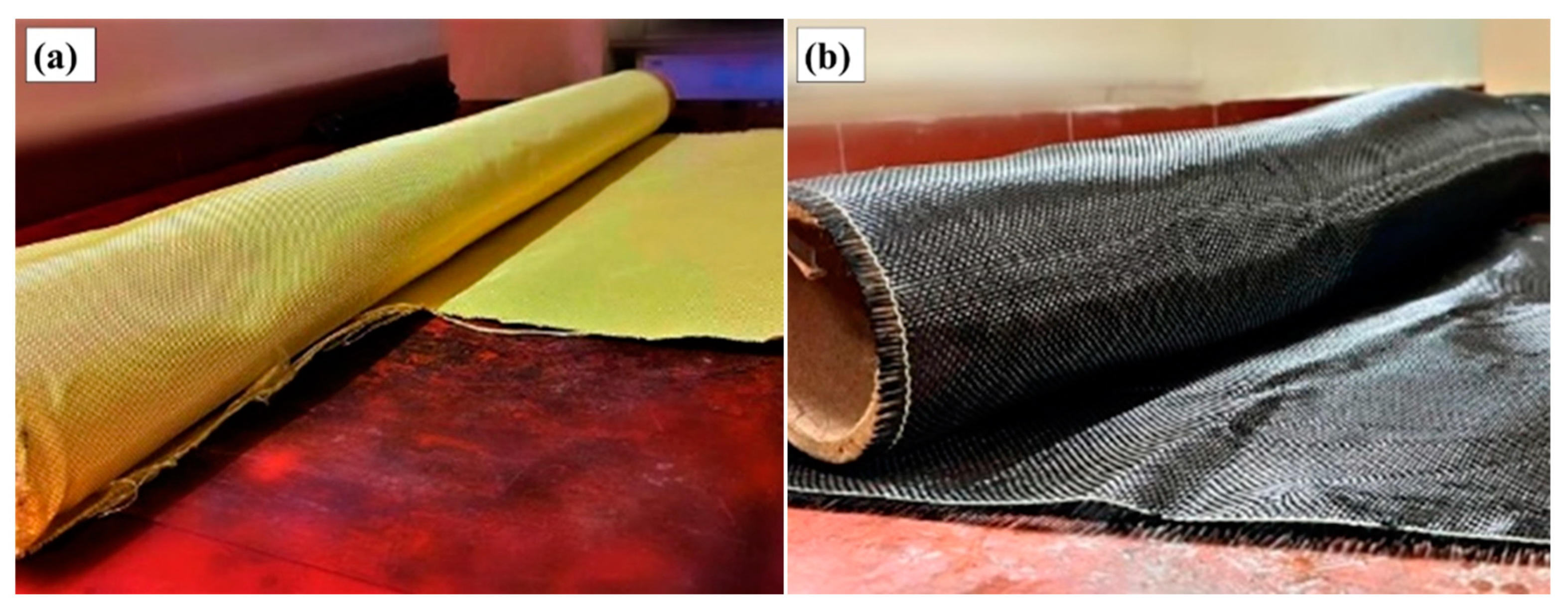
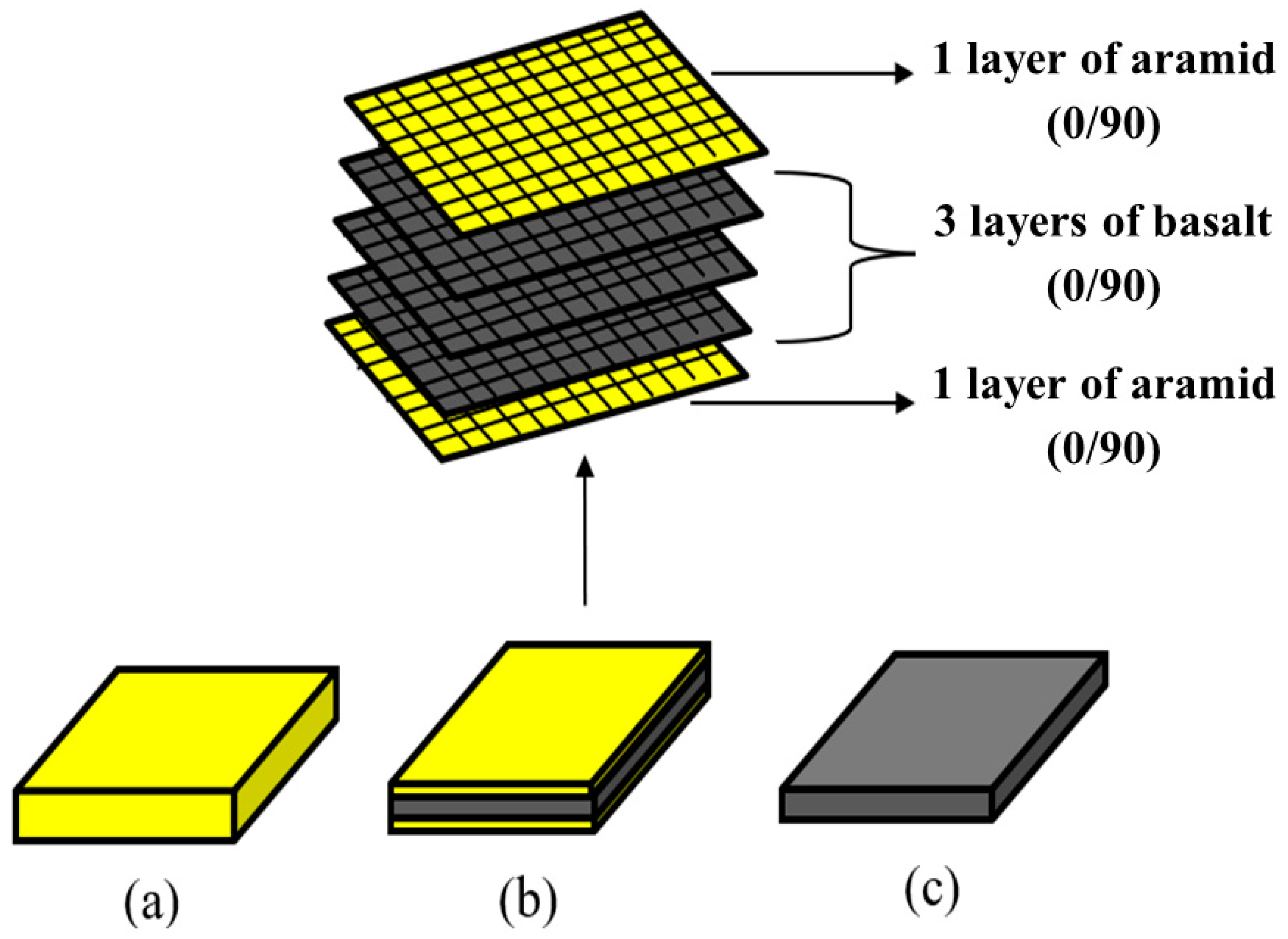
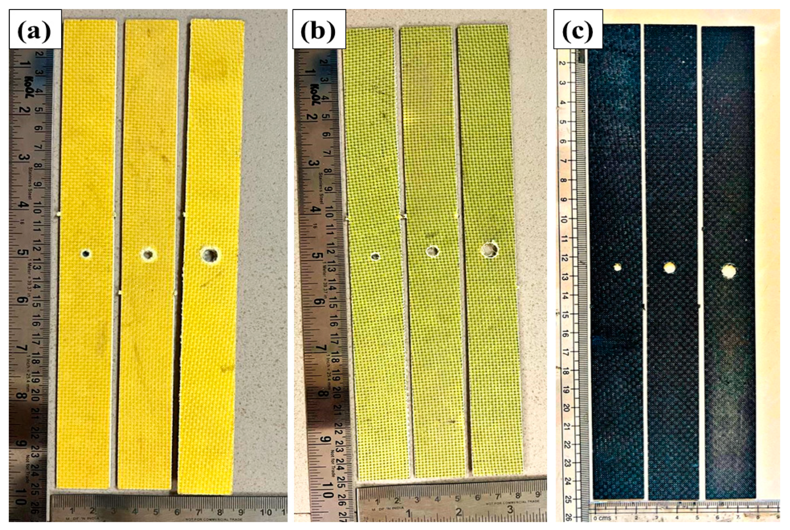
2.1. Materials and Fabrication
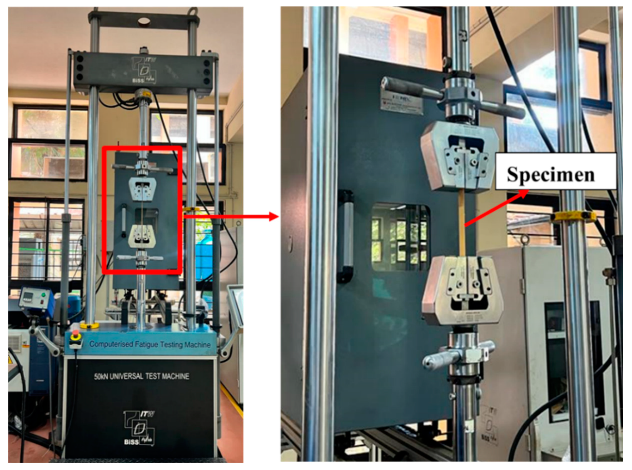
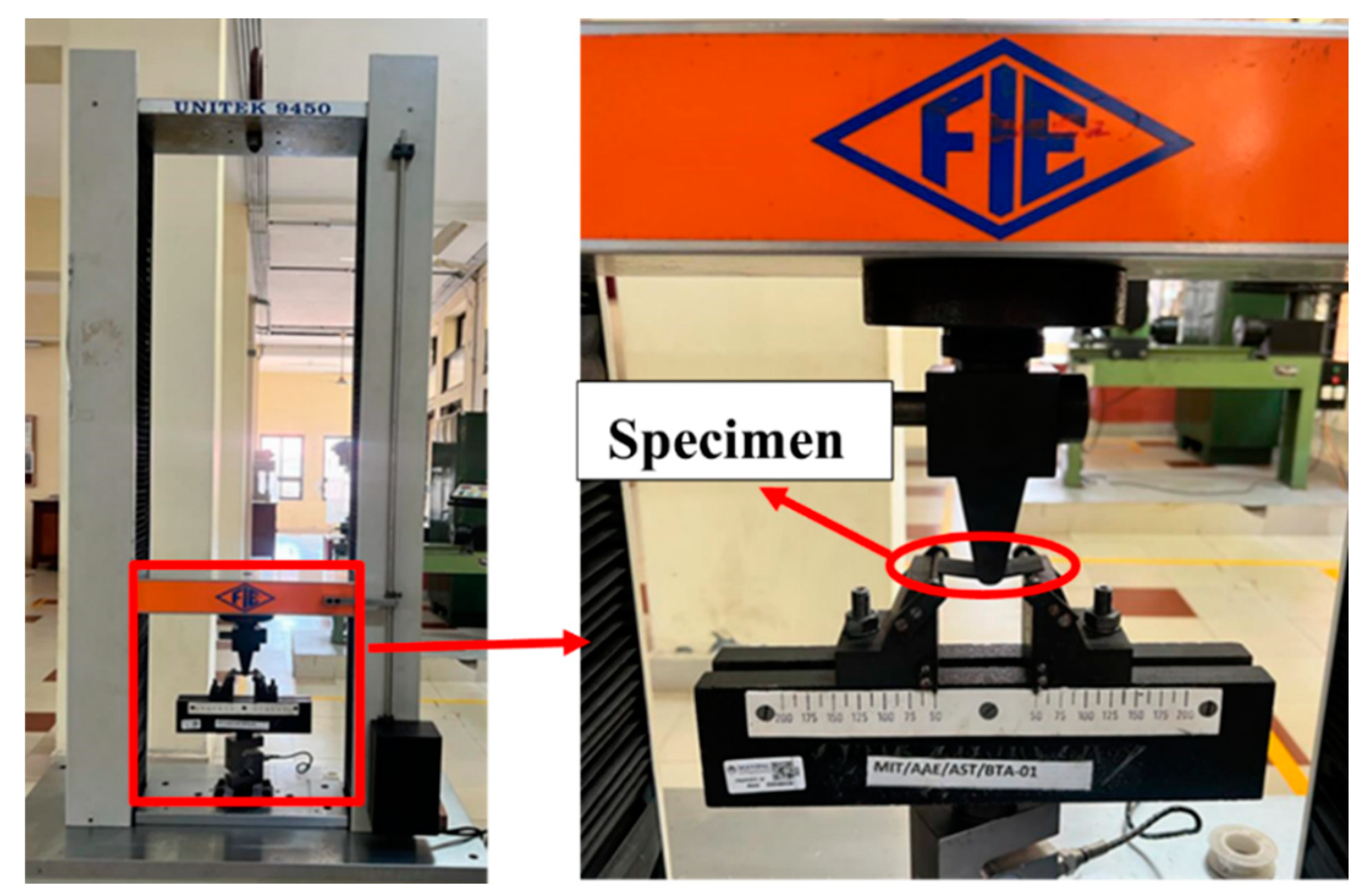
2.2. Tensile Test Set Up
2.3. Flexural Test Setup
3. Results and Discussions
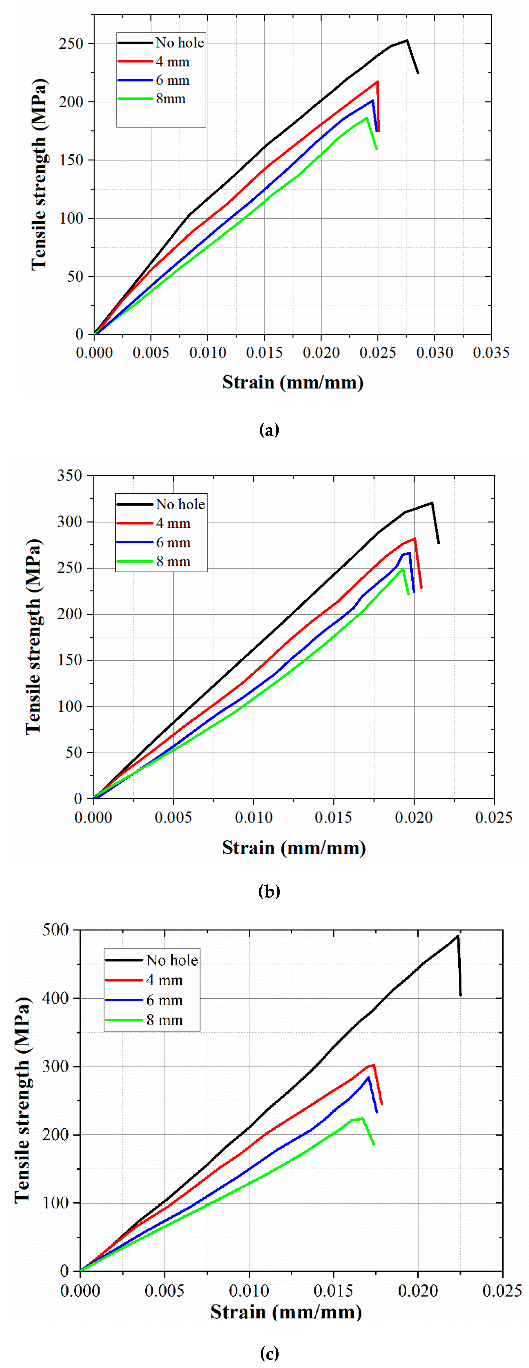
3.1. Tensile Behavior
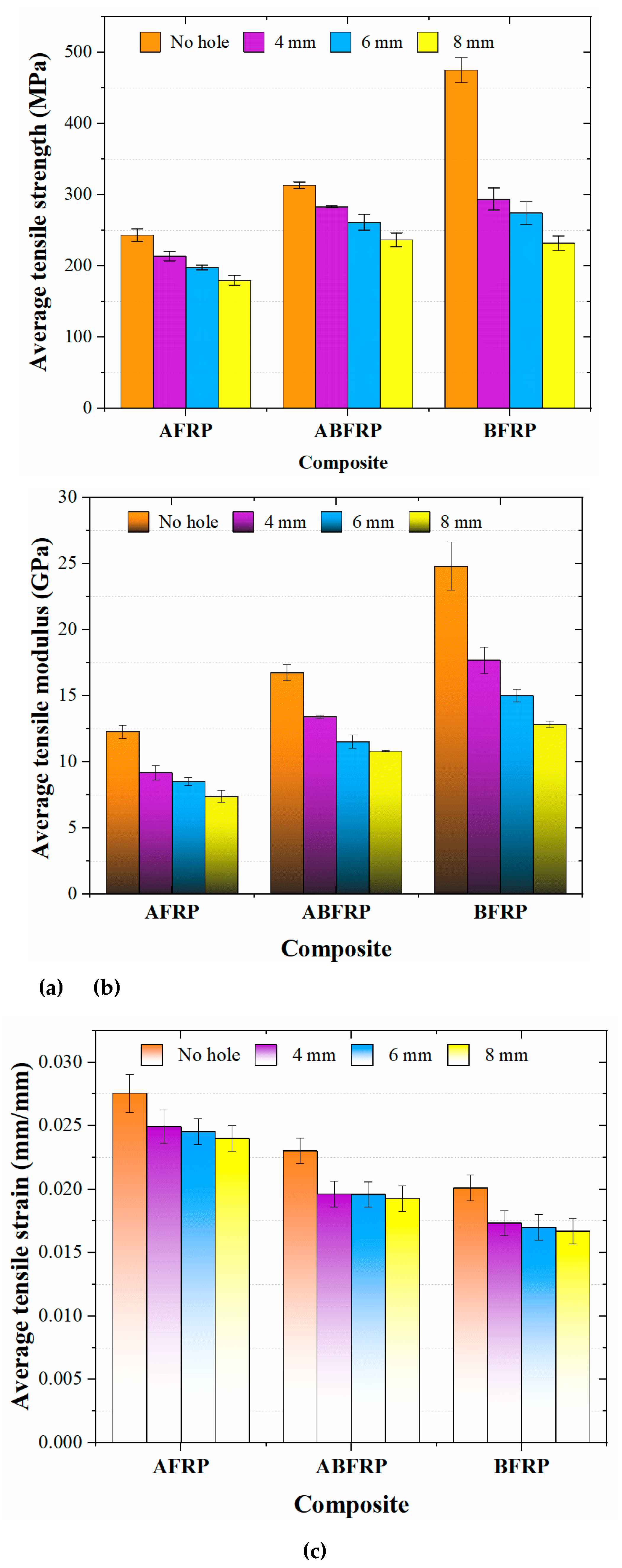
3.2. Tensile Properties
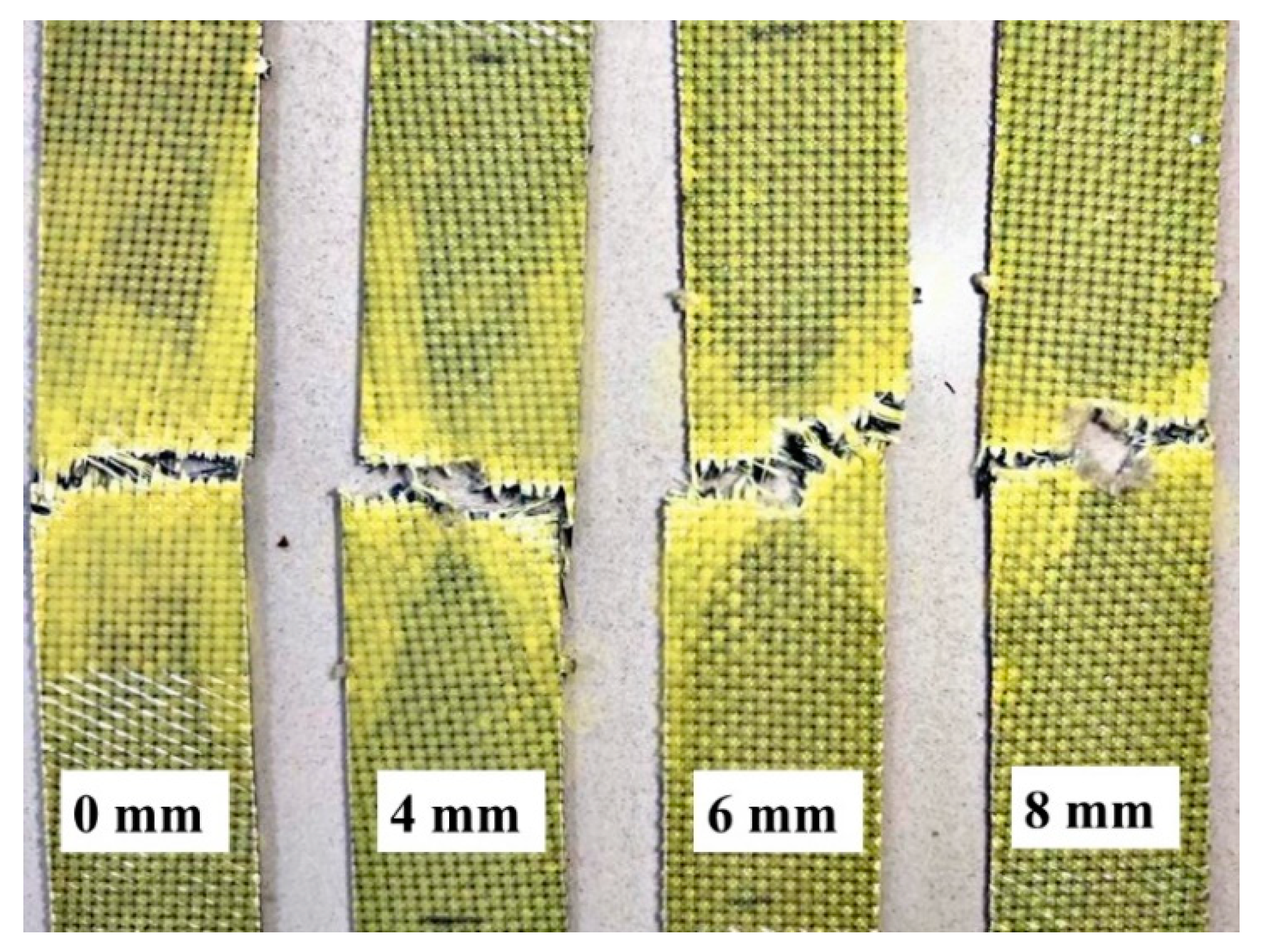
3.3. Damage Assessment of Fractured Tensile Specimens
3.3.1. Specimens without Hole
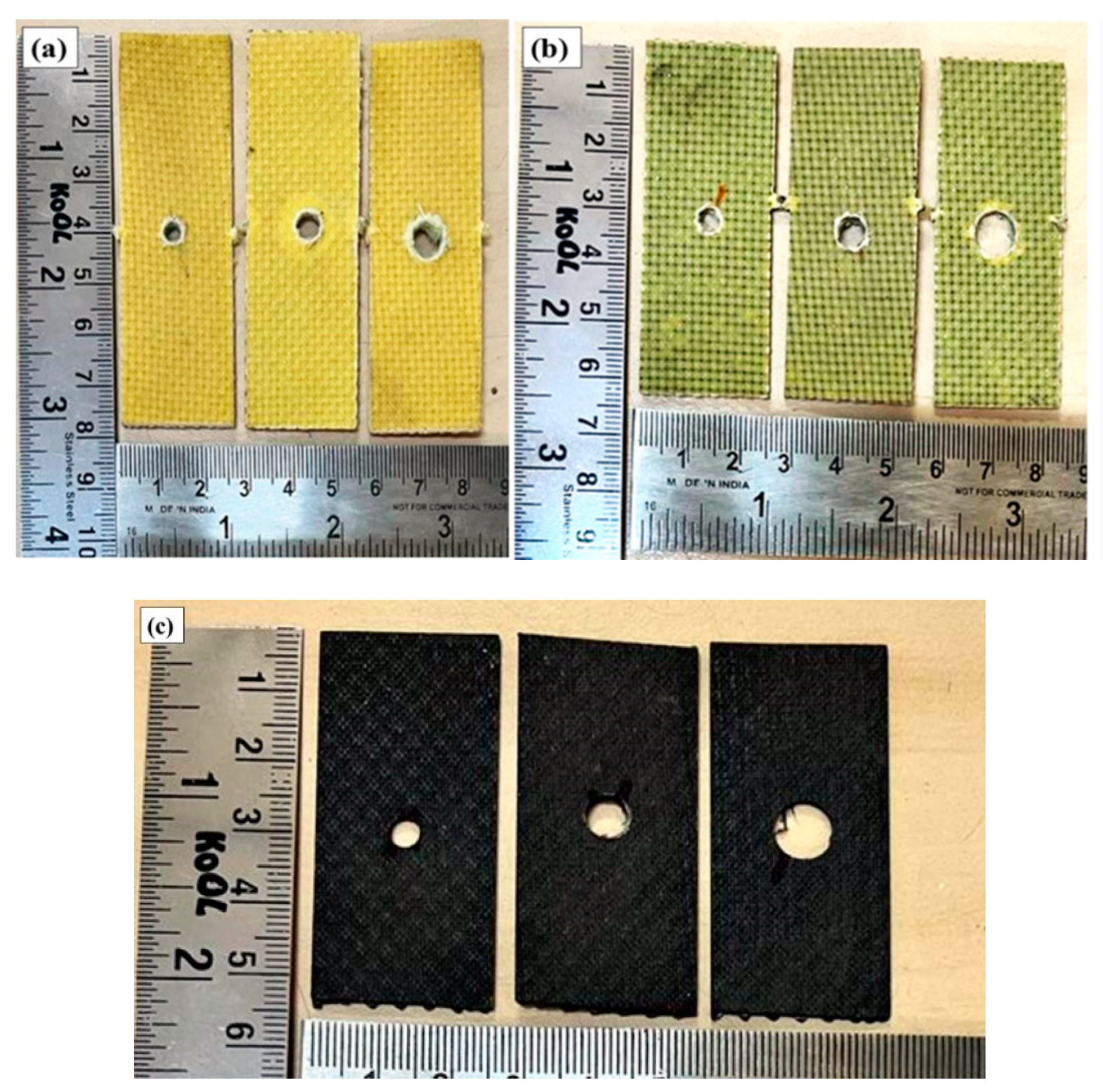
3.3.2. Open Hole Specimens
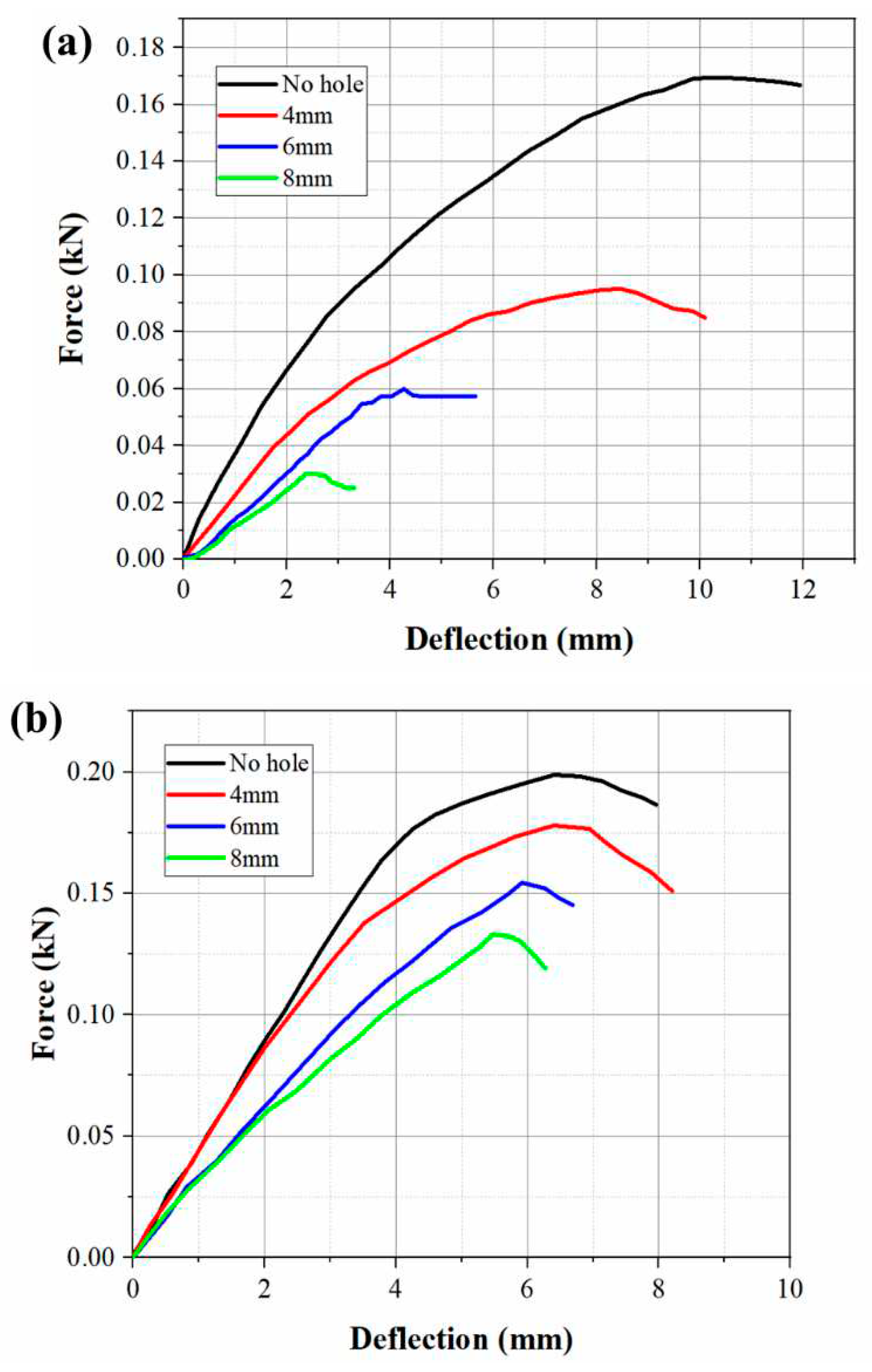
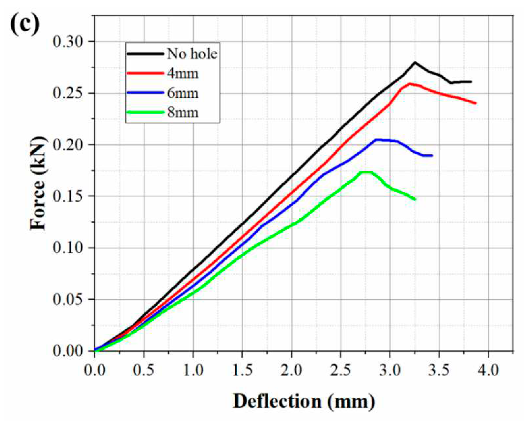
3.4. Flexural Behavior
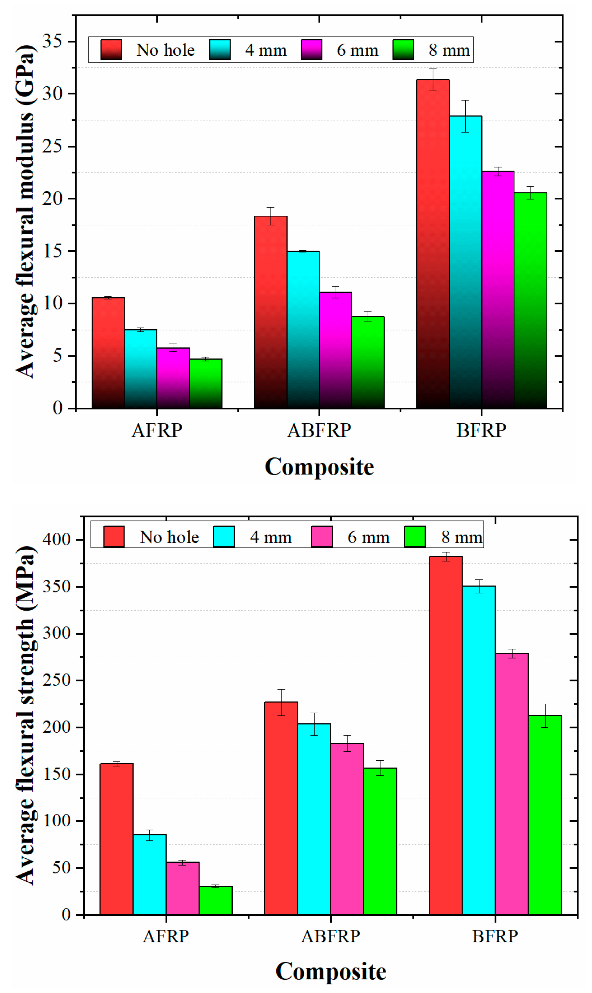
| Mechanical properties | Hole diameter (mm) | AFRP | ABFRP | BFRP |
| Average flexural strength (MPa) | 0 | 160.96 ± 2.42 | 226.68 ± 14.05 | 382.27 ± 4.87 |
| 4 | 85.12 ± 5.78 | 203.53 ± 11.75 | 350.31 ± 7.09 | |
| 6 | 56 ± 2.77 | 182.81 ± 8.62 | 278.95 ± 4.87 | |
| 8 | 30.43 ± 1.47 | 153.56 ± 7.99 | 212.60 ± 12.79 | |
| Young's modulus (GPa) | 0 | 10.55 ± 0.12 | 18.33 ± 0.82 | 31.36 ± 1.05 |
| 4 | 7.52 ± 0.18 | 14.98 ± 0.09 | 27.88 ± 1.52 | |
| 6 | 5.78 ± 0.36 | 11.10 ± 0.55 | 22.61 ± 0.43 | |
| 8 | 4.73 ± 0.18 | 8.75 ± 0.50 | 20.57 ± 0.59 | |
| Strength retention (%) | 4 | 52.88 | 89.78 | 91.63 |
| 6 | 34.79 | 80.64 | 72.97 | |
| 8 | 18.90 | 69.06 | 55.61 |
3.5. Flexural Properties
3.6. Damage Assessment of Fractured Flexural Specimens
4. Conclusions
- The inclusion of basalt layers significantly enhanced the tensile strength and modulus of the hybrid composite laminate. The surface aramid layers in the sandwich type lay-up sequence allowed for larger failure strain by allowing a more ductile failure.
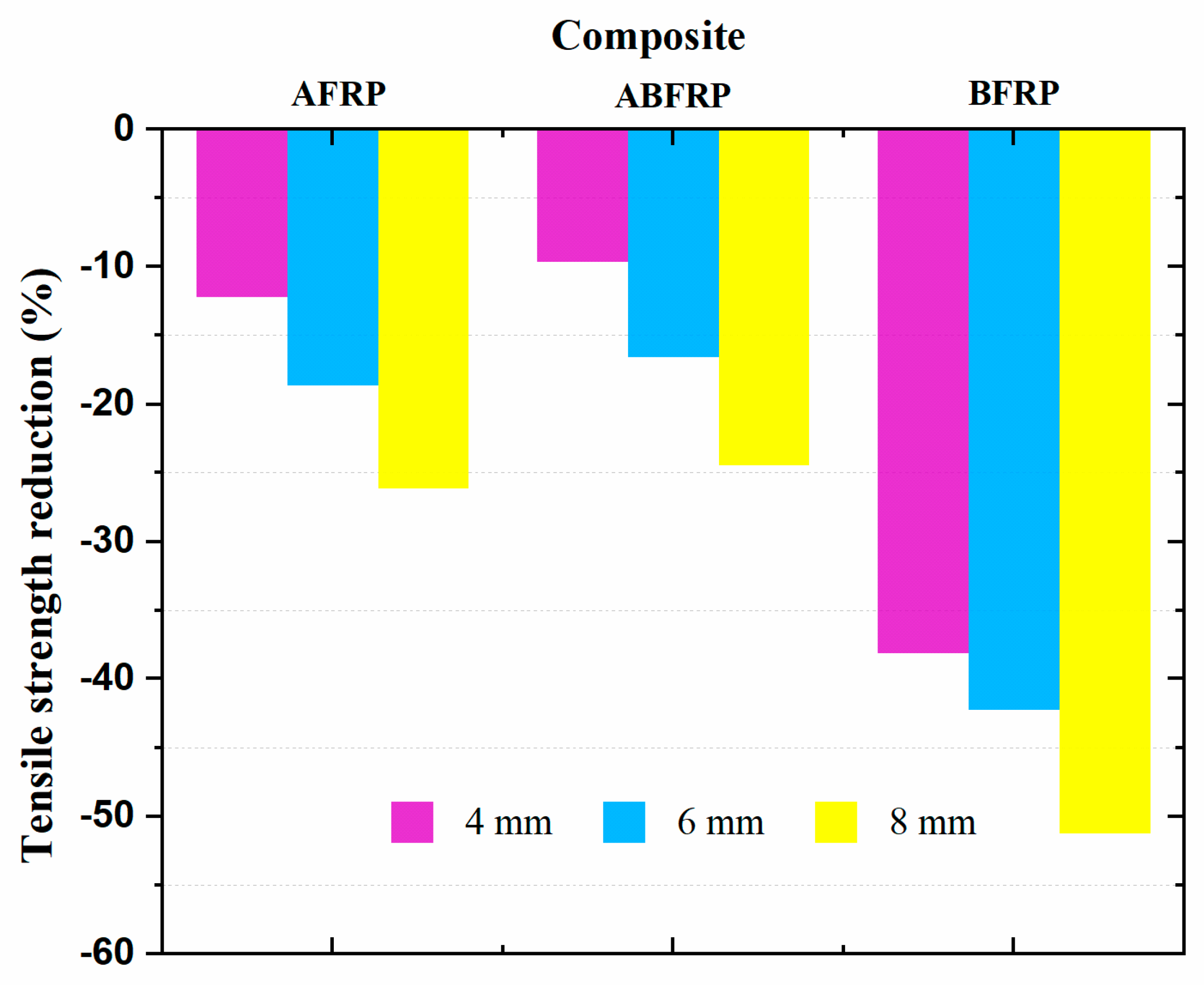
- The stress concentration effect at the hole boundary reduced the material's tensile properties. Strength retention deteriorated for larger holes in the order of AFRP > ABFRP > BFRP.
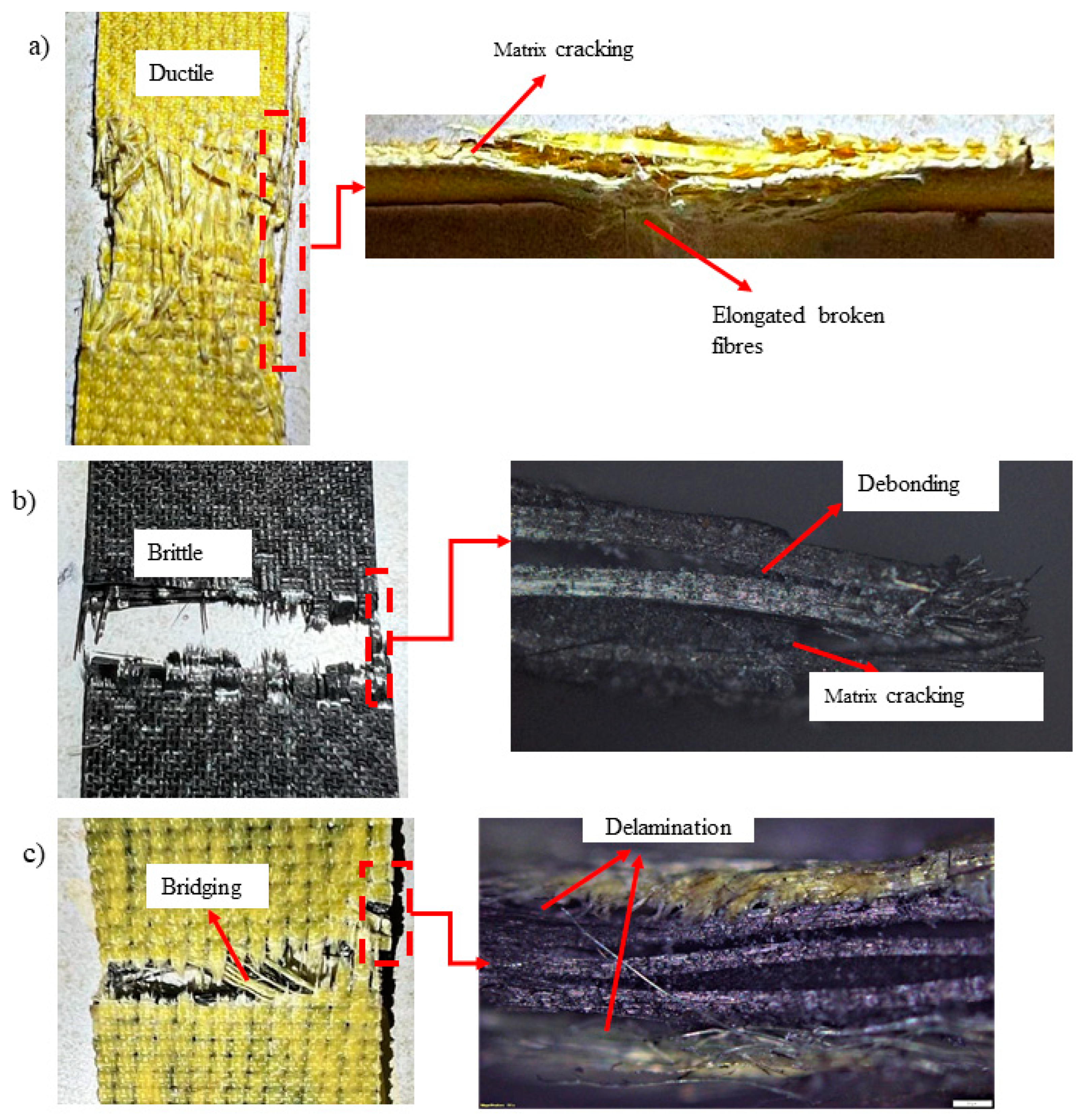
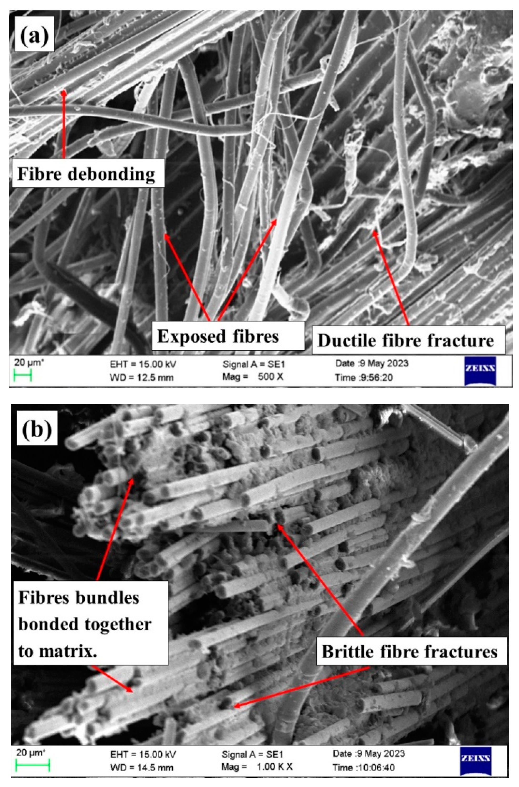
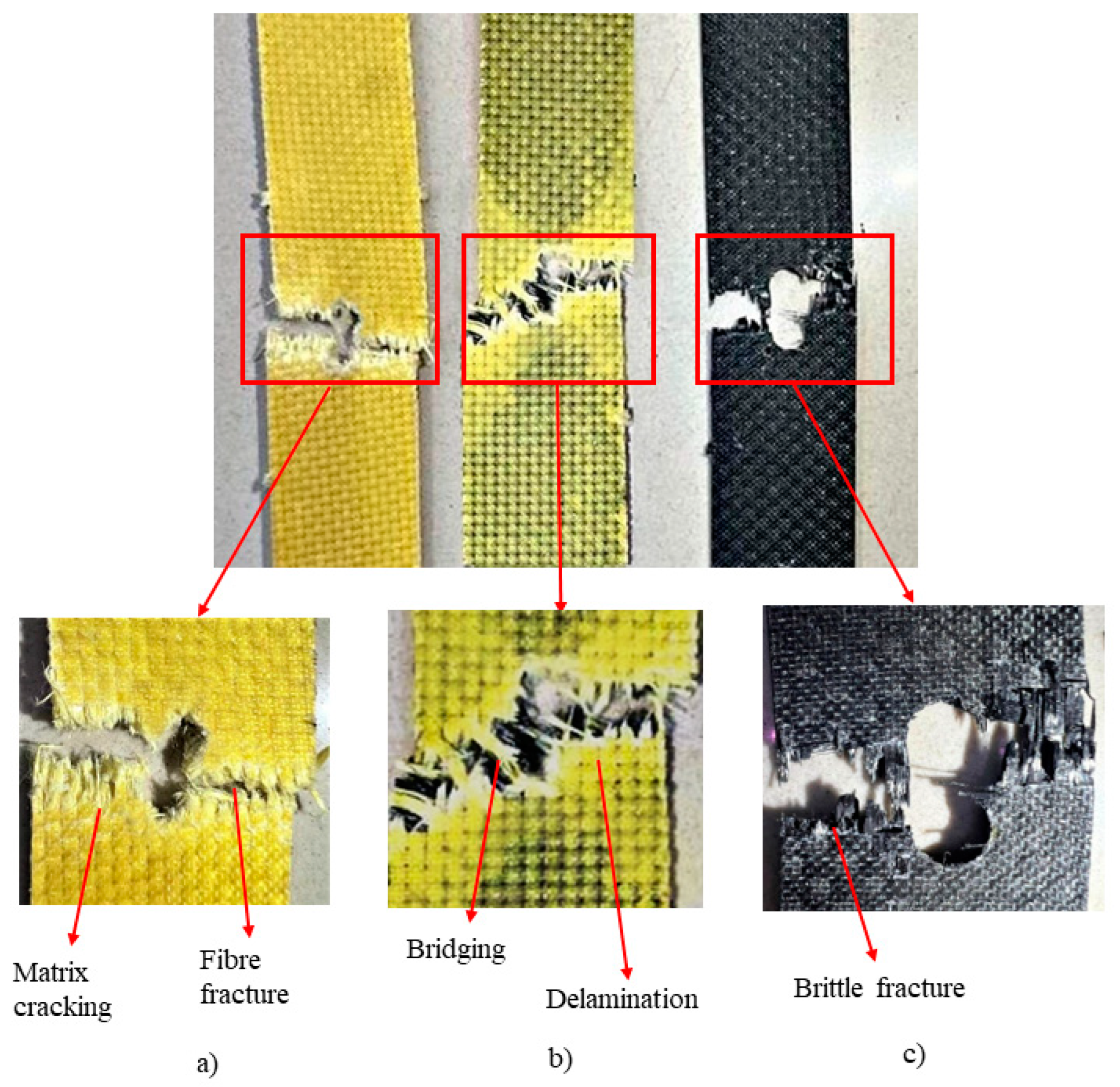
- BFRP laminates were more hole sensitive due to their brittle damage mechanism. Hybrid laminates showed delamination as a major failure mode due to the poor interfacial bonding and difference in mechanical properties between the aramid and basalt fibres.
- Larger holes exhibited smaller delamination area. Matrix cracking, fibre fracture and fibre pull out were the mode of damage observed in the open hole specimens.
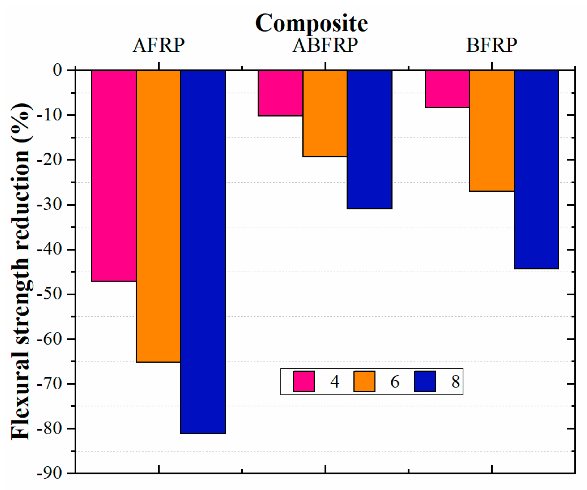
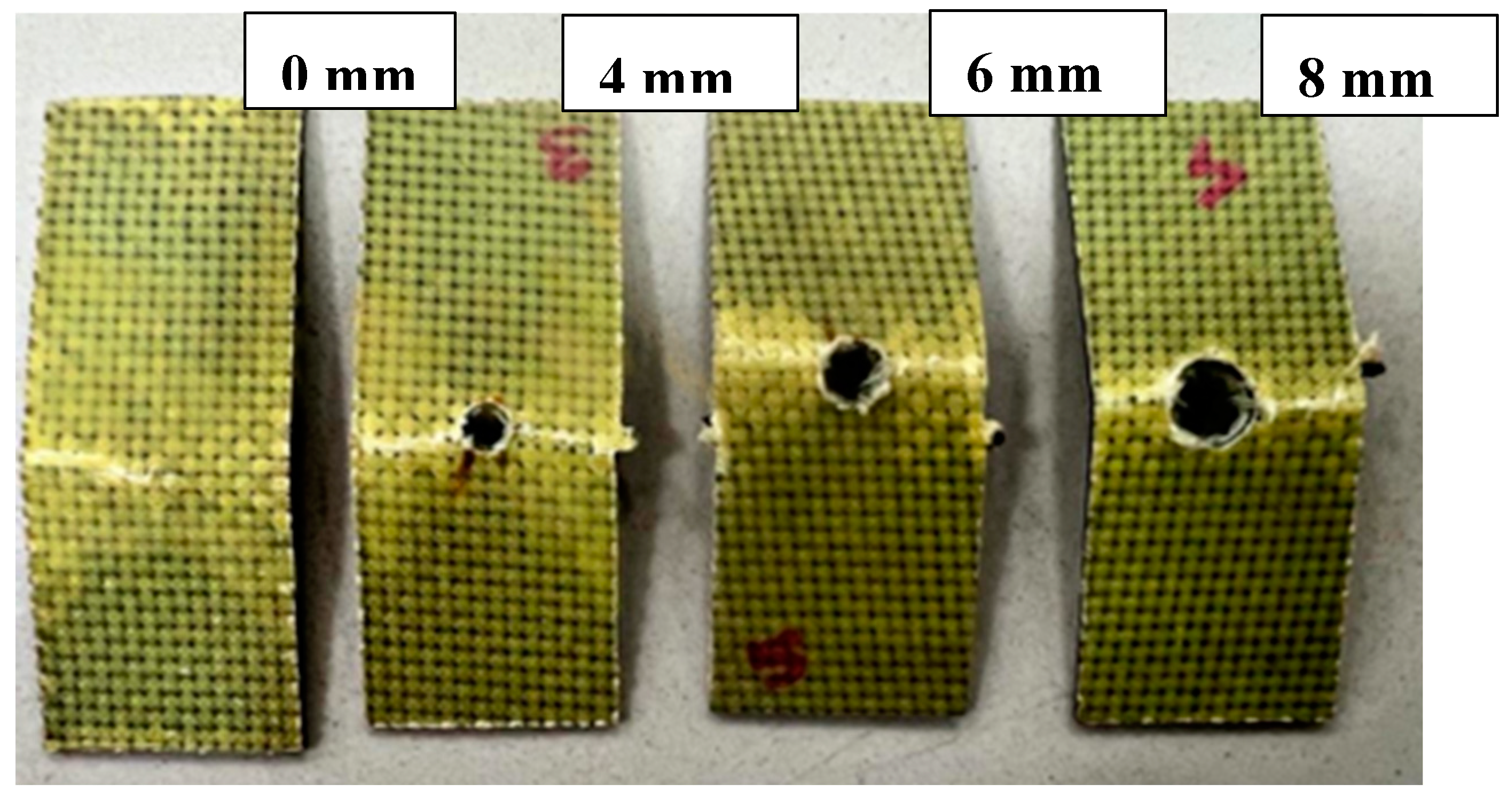
- For specimens without holes, BFRP laminates displayed a flexural strength of 382 MPa, which is higher than that of ABFRP (226 MPa), and AFRP (160 MPa). As the hole diameter increases, the flexural strength reduces significantly. However, the introduction of 8 mm hole caused a decrease in strength of 44.3 %, 32.25 %, 81.09 % for BFRP, ABFRP and AFRP respectively.
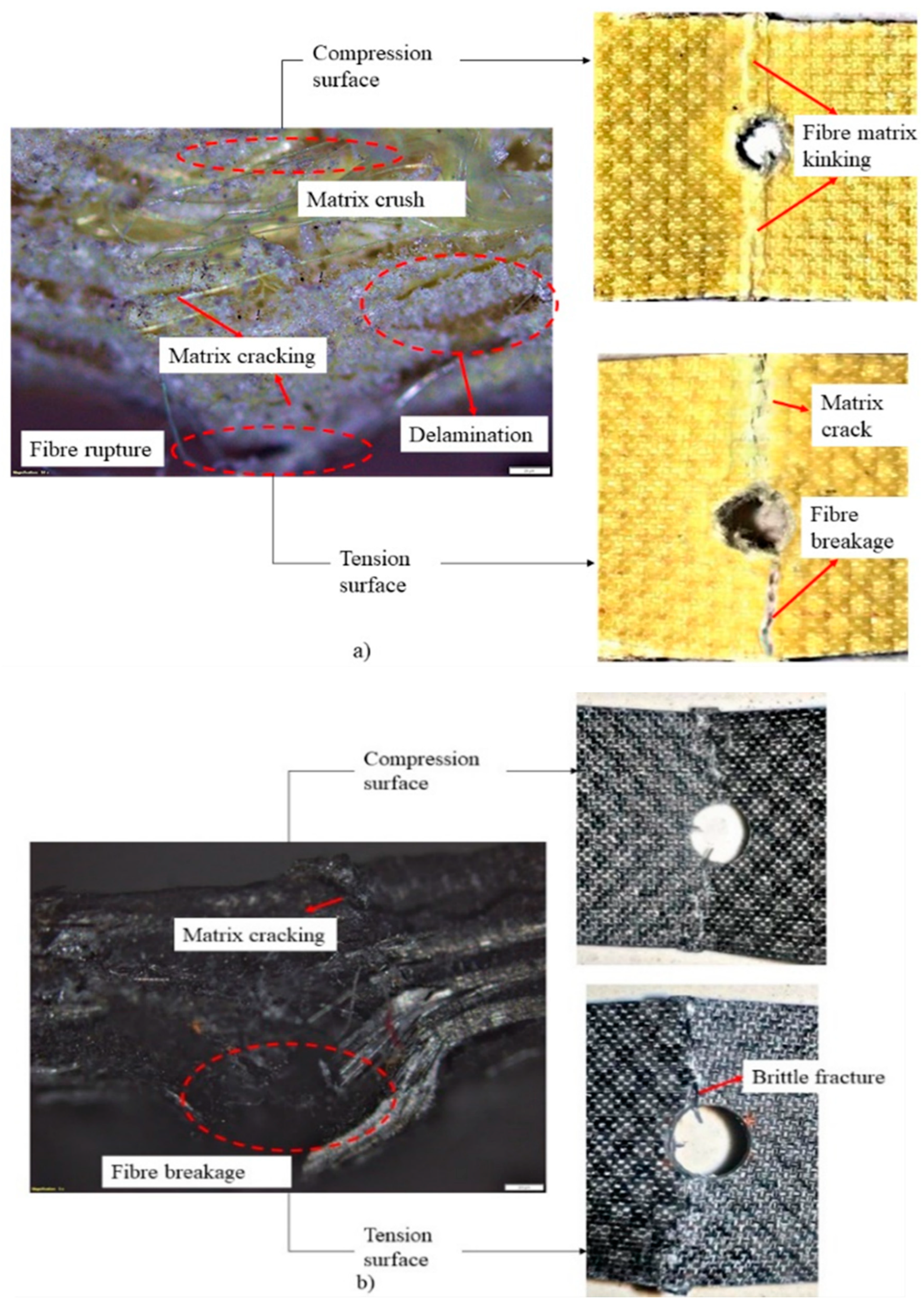
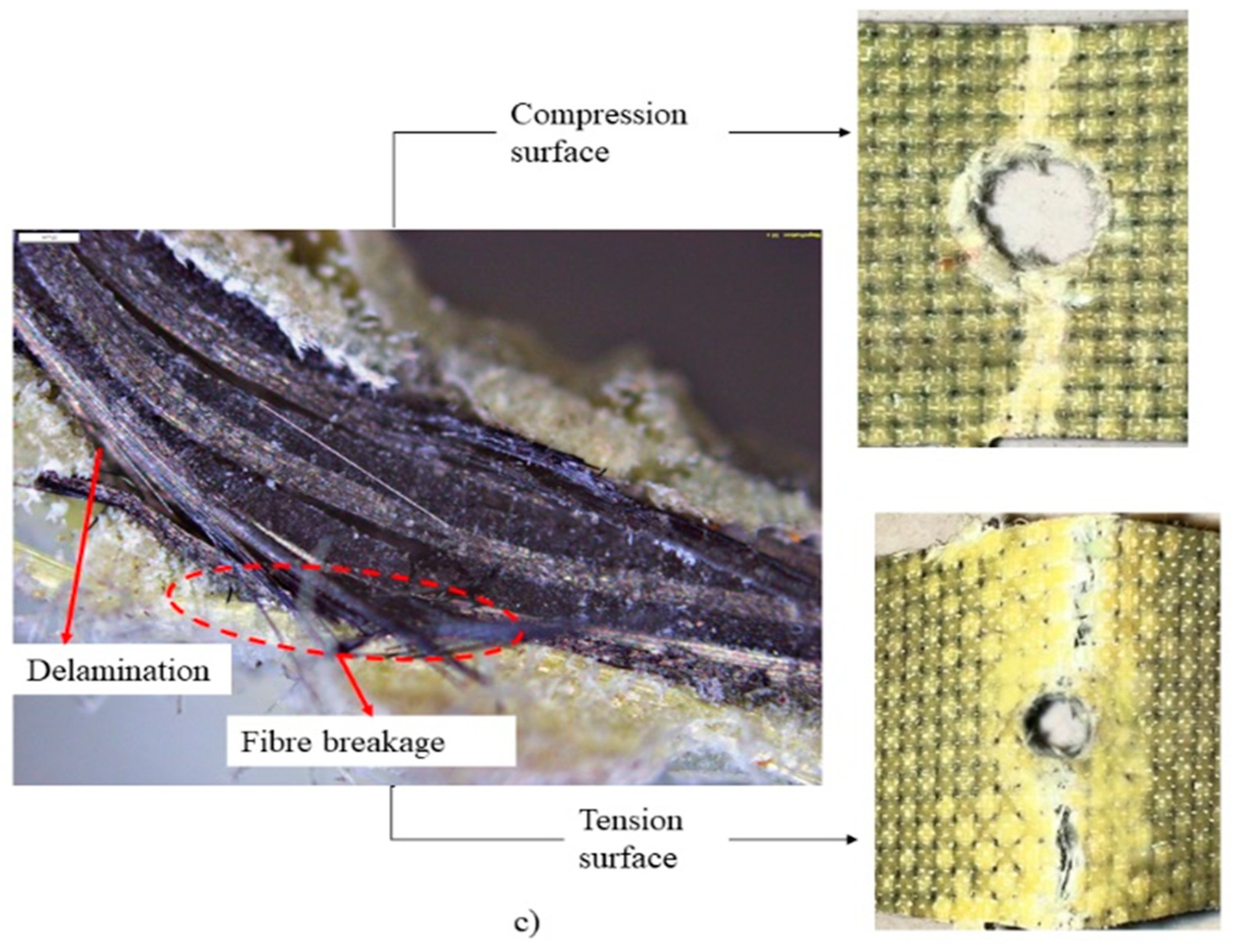
- Aramid fibres exhibited a more pronounced decline in flexural strength with an increase in hole size due to their poor compression and bending properties. However, due to their ability to absorb higher energy and high ductility, resulted in considerable increase in failure strain of the hybrid laminate accompanied by stable failure than BFRP.
- The results obtained from this research on open hole aramid-basalt/epoxy tensile and flexural specimens offer critical data that can be directly applied in engineering and industry to optimize the design and performance of composite structures, enhancing their durability, safety, and overall efficiency.
Author Contributions
Funding
Acknowledgments
Conflicts of Interest
References
- Mallick, P.K. Fiber-Reinforced Composites Materials, Manufacturing and Design, 3rd ed.; CRC Press Taylor & Francis Group: 2007; ISBN 9780849342059.
- Chawla, K.K. Composite Materials: Science and Engineering, 3rd ed.; Springer Science & Business Media: New York, 2012. [Google Scholar]
- Agarwal B D and Broutman L J Analysis and Performance of Fiber Composites, 2nd ed.; John Wiley & Sons Inc. 1990.
- Neto, J.; Queiroz, H.; Aguiar, R.; Lima, R.; Cavalcanti, D.; Banea, M.D. A Review of Recent Advances in Hybrid Natural Fiber Reinforced Polymer Composites. Journal of Renewable Materials 2022, 10, 561–589. [Google Scholar] [CrossRef]
- Pandita, S.D.; Yuan, X.; Manan, M.A.; Lau, C.H.; Subramanian, A.S.; Wei, J. Evaluation of Jute/Glass Hybrid Composite Sandwich: Water Resistance, Impact Properties and Life Cycle Assessment. Journal of Reinforced Plastics and Composites 2014, 33, 14–25. [Google Scholar] [CrossRef]
- CHICHANE, A.; BOUJMAL, R.; El BARKANY, A. Bio-Composites and Bio-Hybrid Composites Reinforced with Natural Fibers: Review. Materials Today: Proceedings 2023, 72, 3471–3479. [Google Scholar] [CrossRef]
- Fiore, V.; Scalici, T.; Di Bella, G.; Valenza, A. A Review on Basalt Fibre and Its Composites. Composites Part B: Engineering 2015, 74, 74–94. [Google Scholar] [CrossRef]
- Czigány, T.; Vad, J.; Pölöskei, K. Basalt Fiber as a Reinforcement of Polymer Composites. Periodica Polytechnica Mechanical Engineering 2005, 49, 3–14. [Google Scholar]
- Elmahdy, A.; Verleysen, P. Mechanical Behavior of Basalt and Glass Textile Composites at High Strain Rates : A Comparison. Polymer Testing 2020, 81, 106224. [Google Scholar] [CrossRef]
- Sarasini, F.; Tirillò, J.; Valente, M.; Ferrante, L.; Cioffi, S.; Iannace, S.; Sorrentino, L. Hybrid Composites Based on Aramid and Basalt Woven Fabrics: Impact Damage Modes and Residual Flexural Properties. Materials and Design 2013, 49, 290–302. [Google Scholar] [CrossRef]
- Bandaru, A.K.; Sachan, Y.; Ahmad, S.; Alagirusamy, R.; Bhatnagar, N. On the Mechanical Response of 2D Plain Woven and 3D Angle-Interlock Fabrics. Composites Part B: Engineering 2017, 118, 135–148. [Google Scholar] [CrossRef]
- Czigány, T. Special Manufacturing and Characteristics of Basalt Fiber Reinforced Hybrid Polypropylene Composites: Mechanical Properties and Acoustic Emission Study. Composites Science and Technology 2006, 66, 3210–3220. [Google Scholar] [CrossRef]
- Dorigato, A.; Pegoretti, A. Flexural and Impact Behaviour of Carbon/Basalt Fibers Hybrid Laminates. Journal of Composite Materials 2014, 48, 1121–1130. [Google Scholar] [CrossRef]
- Zubair, M.; Pai, Y. Review on Impact Response of Polymer Composites. Journal of Mechanical Engineering Research and Developments 2019, 42. [Google Scholar] [CrossRef]
- Pai, Y.; Pai, K.D.; Kini, M.V. A Review on Low Velocity Impact Study of Hybrid Polymer Composites. Materials Today: Proceedings 2021. [CrossRef]
- Fernandes, O.; Dutta, J.; Pai, Y. Effect of Various Factors and Hygrothermal Ageing Environment on the Low Velocity Impact Response of Fibre Reinforced Polymer Composites- a Comprehensive Review. Cogent Engineering 2023, 10. [Google Scholar] [CrossRef]
- Agarwal, S.; Pai, Y.; Pai, D.; Mahesha, G.T. Assessment of Ageing Effect on the Mechanical and Damping Characteristics of Thin Quasi-Isotropic Hybrid Carbon-Kevlar / Epoxy Intraply Composites and Damping Characteristics of Thin Intraply Composites. Cogent Engineering 2023, 10. [Google Scholar] [CrossRef]
- Swolfs, Y.; Gorbatikh, L.; Verpoest, I. Composites : Part A Fibre Hybridisation in Polymer Composites : A Review. COMPOSITES PART A 2014, 67, 181–200. [Google Scholar] [CrossRef]
- Gupta, M.K.; Srivastava, R.K. A Review on Characterization of Hybrid Fibre Reinforced Polymer Composite. Gupta MK American Journal of Polymer Science & Engineering 2016, 4, 1–7. [Google Scholar]
- Phillips, L.N. The Hybrid Effect - Does It Exist? Composites 1976, 7, 7–8. [Google Scholar] [CrossRef]
- Pandya, K.S.; Veerraju, C.; Naik, N.K. Hybrid Composites Made of Carbon and Glass Woven Fabrics under Quasi-Static Loading. Materials and Design 2011, 32, 4094–4099. [Google Scholar] [CrossRef]
- Pai, Y.; Pai K, D.; Kini, M.V. Experimental Investigations on the Moisture Absorption and Mechanical Behaviour of Basalt-Aramid/Epoxy Hybrid Interply Composites under Different Ageing Environments. Cogent Engineering 2022, 9, 0–20. [Google Scholar] [CrossRef]
- Wang, X.; Hu, B.; Feng, Y.; Liang, F.; Mo, J.; Xiong, J.; Qiu, Y. Low Velocity Impact Properties of 3D Woven Basalt/Aramid Hybrid Composites. Composites Science and Technology 2008, 68, 444–450. [Google Scholar] [CrossRef]
- Pai, Y.; Pai, D.K.; Kini, M.V. Evaluation of the Mechanical Characteristics of Hygrothermally Aged 2-D Basalt-Aramid/Epoxy Hybrid Interply Composites. Journal of Physics: Conference Series 2021, 2070. [Google Scholar] [CrossRef]
- Pai, Y.; Dayananda Pai, K.; Vijaya Kini, M. Effect of Ageing Conditions on the Low Velocity Impact Behavior and Damage Characteristics of Aramid-Basalt/Epoxy Hybrid Interply Composites. Engineering Failure Analysis 2023, 152, 107492. [Google Scholar] [CrossRef]
- Jule, L.T.; Ramaswamy, K.; Nagaprasad, N.; Shanmugam, V.; Vignesh, V. Design and Analysis of Serial Drilled Hole in Composite Material. Materials Today: Proceedings 2021, 45, 5759–5763. [Google Scholar] [CrossRef]
- Caminero, M.A.; Lopez-Pedrosa, M.; Pinna, C.; Soutis, C. Damage Monitoring and Analysis of Composite Laminates with an Open Hole and Adhesively Bonded Repairs Using Digital Image Correlation. Composites Part B: Engineering 2013, 53, 76–91. [Google Scholar] [CrossRef]
- Guo, Q.; Zhang, Y.; Li, D.; Lv, Q.; Sun, X.; Ma, M.; Chen, L. Experimental and Numerical Investigation of Open-Hole Tensile Properties and Damage Mechanisms of 3D Woven Composites under Weft-Loading. Thin-Walled Structures 2021, 161, 107455. [Google Scholar] [CrossRef]
- Green, B.G.; Wisnom, M.R.; Hallett, S.R. An Experimental Investigation into the Tensile Strength Scaling of Notched Composites. 2007, 38, 867–878. [CrossRef]
- Kumar, S.A.; Rajesh, R.; Pugazhendhi, S. A Review of Stress Concentration Studies on Fibre Composite Panels with Holes/Cutouts. Proceedings of the Institution of Mechanical Engineers, Part L: Journal of Materials: Design and Applications 2020, 234, 1461–1472. [Google Scholar] [CrossRef]
- Kumar, A.; Patel, S.; Sachan, Y.; Ahmad, S.; Alagirusamy, R. Composites : Part A Mechanical Behavior of Kevlar / Basalt Reinforced Polypropylene Composites. Composites Part A 2016, 90, 642–652. [Google Scholar] [CrossRef]
- Sarasini, F.; Tirillò, J.; Valente, M.; Valente, T.; Cioffi, S.; Iannace, S.; Sorrentino, L. Effect of Basalt Fiber Hybridization on the Impact Behavior under Low Impact Velocity of Glass/Basalt Woven Fabric/Epoxy Resin Composites. Composites Part A: Applied Science and Manufacturing 2013, 47, 109–123. [Google Scholar] [CrossRef]
- Sarasini, F.; Tirillò, J.; Ferrante, L.; Valente, M.; Valente, T.; Lampani, L.; Gaudenzi, P.; Cioffi, S.; Iannace, S.; Sorrentino, L. Drop-Weight Impact Behaviour of Woven Hybrid Basalt-Carbon/Epoxy Composites. Composites Part B: Engineering 2014, 59, 204–220. [Google Scholar] [CrossRef]
- Sarasini, F.; Tirillò, J.; D’Altilia, S.; Valente, T.; Santulli, C.; Touchard, F.; Chocinski-Arnault, L.; Mellier, D.; Lampani, L.; Gaudenzi, P. Damage Tolerance of Carbon/Flax Hybrid Composites Subjected to Low Velocity Impact. Composites Part B: Engineering 2016, 91, 144–153. [Google Scholar] [CrossRef]
- Dorey, G.; Sidey, G.R.; Hutchings, J. Impact Properties of Carbon Fibre / Kevlar 49 Fibre Hydrid Composites. Composites 1978, 9, 25–32. [Google Scholar] [CrossRef]
- Vasudevan, A.; Senthil Kumaran, S.; Naresh, K.; Velmurugan, R.; Shankar, K. Advanced 3D and 2D Damage Assessment of Low Velocity Impact Response of Glass and Kevlar Fiber Reinforced Epoxy Hybrid Composites. Advances in Materials and Processing Technologies 2018, 4, 493–510. [Google Scholar] [CrossRef]
- Pai, Y.; Kini, M.V.; Engineering, A. Effect of Aramid Fabric Orientation Angle on the Mechanical Characteristics of Basalt-Aramid / Epoxy Hybrid Interply Composites. Materials Research 2021, 24. [Google Scholar] [CrossRef]
- Kanitkar, Y.M.; Kulkarni, A.P.; Wangikar, K.S. Investigation of Flexural Properties of Glass-Kevlar Hybrid Composite. 2016, 1, 25–29.
- Chuaqui, T.R.C.; Nielsen, M.W.D.; Colton, J.; Butler, R.; Rhead, A.T. Effects of Ply Angle and Blocking on Open-Hole Tensile Strength of Composite Laminates : A Design and Certification Perspective. Composites Part B 2021, 207, 108582. [Google Scholar] [CrossRef]
- Oz, F.E.; Mehdikhani, M.; Ersoy, N.; Lomov, S. V In-Situ Imaging of Inter- and Intra-Laminar Damage in Open-Hole Tension Tests of Carbon Fi Bre-Reinforced Composites. Composite Structures 2020, 244, 112302. [Google Scholar] [CrossRef]
- Kannan, T.G.; Mou, C.; Bing, K. Composites : Part B Influence of Laminate Lay-up, Hole Size and Coupling Agent on the Open Hole Tensile Properties of Flax Yarn Reinforced Polypropylene Laminates. Composites Part B 2014, 57, 80–85. [Google Scholar] [CrossRef]
- Vaidya, R.S.; Klug, J.C.; Sun, C.T. Effect of Ply Thickness on Fracture of Notched Composite Laminates Introduction. 1998, 36.
- Cunningham, D.; Harries, K.A.; Bell, A.J. Open-Hole Tension Capacity of Pultruded GFRP Having Staggered Hole Arrangement. Engineering Structures 2015, 95, 8–15. [Google Scholar] [CrossRef]
- Beyene, A.T.; Belingardi, G.; Koricho, E.G. Effect of Notch on Quasi-Static and Fatigue Flexural Performance of Twill E-Glass / Epoxy Composite. Composite Structures 2016, 153, 825–842. [Google Scholar] [CrossRef]
- Yu, J.; Pan, Z.; Cai, Q.; Zhang, F.; Wu, Z. Open Hole Tensile Behavior of Plain Woven Carbon/Glass Hybrid Composites. International Journal of Mechanical Sciences 2023, 246, 108142. [Google Scholar] [CrossRef]
- Belgacem, L.; Ouinas, D.; Aurelio, J.; Olay, V.; Argüelles, A. Experimental Investigation of Notch e Ff Ect and Ply Number on Mechanical Behavior of Interply Hybrid Laminates (Glass / Carbon / Epoxy). Composites Part B 2018, 145, 189–196. [Google Scholar] [CrossRef]
- Sun, G.; Wang, L.; Chen, D.; Luo, Q. International Journal of Mechanical Sciences Tensile Performance of Basalt Fiber Composites with Open Circular Holes and Straight Notches. International Journal of Mechanical Sciences 2020, 176, 105517. [Google Scholar] [CrossRef]
- Shaari, N.; Jumahat, A.; Abdullah, S.A.; Hadderi, A.Z. Effect of Hybridization on Open-Hole Tension Properties of Woven Kevlar/Glass Fiber Hybrid Composite Laminates. Jurnal Teknologi 2015, 76, 91–96. [Google Scholar] [CrossRef]
- Shaari, N.; Jumahat, A. Hole Size Effects on the Open Hole Tensile Properties of Woven Kevlar-Glass Fibre Hybrid Composite Laminates. 2017, 25, 309–318.
- Sebaey, T.A.; Wagih, A. Flexural Properties of Notched Carbon – Aramid Hybrid Composite Laminates. 2019. [CrossRef]
- ASTM D3039 / D3039M-14 Standard Test Method for Tensile Properties of Polymer Matrix Composite; ASTM International, West Conshohocken, PA, 2014.
- ASTM D3171 Standard Test Methods for Constituent Content of Composite Materials. 2011, 1–11.
- D7264, A. Standard Test Method for Flexural Properties of Polymer Matrix Composite; 2020.
- ASTM D790 Standard Test Methods for Flexural Properties of Unreinforced and Reinforced Plastics and Electrical Insulating Materials 2021, 1–6.
- Bozkurt, Y. Hybridization Effects on Tensile and Bending Behavior of Aramid / Basalt Fiber Reinforced Epoxy Composites. 2015.
- Velumayil, R. Hybridization Effect on Mechanical Properties of Basalt / Kevlar / Epoxy Composite Laminates. 2022. [CrossRef]
- Vara, V.; Talupula, S. ScienceDirect A Review on Reinforcement of Basalt and Aramid ( Kevlar 129 ) Fibers. Materials Today: Proceedings 2018, 5, 5993–5998. [Google Scholar] [CrossRef]
- Safri, S.N.A.; Sultan, M.T.H.; Jawaid, M.; Jayakrishna, K. Impact Behaviour of Hybrid Composites for Structural Applications: A Review. Composites Part B: Engineering 2018, 133, 112–121. [Google Scholar] [CrossRef]
- Chowdhury, I.R.; Nash, N.H.; Portela, A.; Dowd, N.P.O.; Comer, A.J. Analysis of Failure Modes for a Non-Crimp Basalt Fiber Reinforced Epoxy Composite under Flexural and Interlaminar Shear Loading. Composite Structures 2020, 245, 112317. [Google Scholar] [CrossRef]
- Bulut, M. Mechanical Characterization of Basalt/Epoxy Composite Laminates Containing Graphene Nanopellets. Composites Part B 2017. [Google Scholar] [CrossRef]
- Bazan, P.; Wierzbicka-miernik, A. A Novel Hybrid Composites Based on Biopolyamide 10. 10 with Basalt / Aramid Fibers : Mechanical and Thermal Investigation. 2021, 223. [Google Scholar] [CrossRef]
- Hayashi, T. On the Improvement of Mechanical Properties of Composites by Hybrid Composition. In Proceedings of the In: Proc 8th int reinforced plastics conference; 1972; pp. 149–152. [Google Scholar]
- Pai, Y.; Pai K, D.; Kini, M.V. Effect of Aramid Fabric Orientation Angle on the Mechanical Characteristics of Basalt-Aramid/Epoxy Hybrid Interply Composites. Materials Research 2021, 24. [Google Scholar] [CrossRef]
- Khashaba, U.A.; Selmy, A.I.; Megahed, M. GFR / EPOXY Composites under Static and Fatigue Loads. 2007, 81, 606–613. [CrossRef]
- Wisnom, M.R.; Khan, B.; Hallett, S.R. Size Effects in Unnotched Tensile Strength of Unidirectional and Quasi-Isotropic Carbon/Epoxy Composites. Composite Structures 2008, 84, 21–28. [Google Scholar] [CrossRef]
- Z. Carl The Flexural Strength of Aramid Fiber Composites. 1978, 12, 422–430.
- Czél, G.; Wisnom, M.R. Demonstration of Pseudo-Ductility in High Performance Glass/Epoxy Composites by Hybridisation with Thin-Ply Carbon Prepreg. Composites Part A: Applied Science and Manufacturing 2013, 52, 23–30. [Google Scholar] [CrossRef]
- Basha, M.; Wagih, A.; Melaibari, A.; Lubineau, G.; Eltaher, M.A. Microporous and Mesoporous Materials On the Impact Damage Resistance and Tolerance Improvement of Hybrid CFRP / Kevlar Sandwich Composites. 2022, 333, 1–11.
- Wisnom, M.R.; Hallett, S.R. The Role of Delamination in Strength, Failure Mechanism and Hole Size Effect in Open Hole Tensile Tests on Quasi-Isotropic Laminates. Composites Part A: Applied Science and Manufacturing 2009, 40, 335–342. [Google Scholar] [CrossRef]
- Mariatti, M.; Nasir, M.; Ismail, H. The Effects of Hole Locations and Hole Sizes on Damaged Behaviour of Woven Thermoplastic Composites; 2001; Vol. 20;
- Subagia, I.D.G.A.; Kim, Y.; Tijing, L.D.; Sang, C.; Kyong, H. Composites : Part B Effect of Stacking Sequence on the Flexural Properties of Hybrid Composites Reinforced with Carbon and Basalt Fibers. COMPOSITES PART B 2014, 58, 251–258. [Google Scholar] [CrossRef]
- Bazhenov, S.L. Bending Failure of Aramid Fibre-Reinforced Composite. Composites 1995, 26, 757–765. [Google Scholar] [CrossRef]
- Kretsis, G. A Review of the Tensile, Compressive, Flexural and Shear Properties of Hybrid Fibre-Reinforced Plastics. Composites 1987, 18, 13–23. [Google Scholar] [CrossRef]
| Material | Surface Density (g/m2) | Density(g/cm3) | Elastic modulus (GPa) |
| Basalt | 400 | 1.44 | 89 |
| Aramid | 480 | 2.8 | >72 |
| Resin (CT/E 556) | - | 1.15 | - |
| Hardener (CT/H 951) | - | 0.97 | - |
| Mechanical properties | Hole diameter (mm) | AFRP | ABFRP | BFRP |
| Average tensile strength (MPa) | 0 | 243.11 ± 8.74 | 313.12 ± 4.80 | 474.54 ± 17.52 |
| 4 | 213.52 ± 6.52 | 282.9 ± 1.56 | 293.83 ± 15.52 | |
| 6 | 197.84 ± 3.20 | 261.2 ± 11.10 | 274.39 ± 16.20 | |
| 8 | 179.68 ± 6.73 | 241.58 ± 9.64 | 231.65 ± 10.19 | |
| Young's modulus (GPa) | 0 | 12.28± 0.41 | 16.74 ± 0.59 | 24.8 ± 1.83 |
| 4 | 9.18 ± 0.55 | 13.43 ± 0.11 | 17.68 ± 0.99 | |
| 6 | 8.51 ± 0.31 | 11.52 ± 0.5 | 15.02 ± 0.47 | |
| 8 | 7.39 ± 0.44 | 10.8 ± 0.05 | 12.83 ± 0.23 | |
| Failure strain | 0 | 0.0275 | 0.0211 | 0.0223 |
| 4 | 0.0249 | 0.0196 | 0.0173 | |
| 6 | 0.0245 | 0.0196 | 0.0170 | |
| 8 | 0.0239 | 0.0192 | 0.0167 | |
| Strength retention (%) | 4 | 87.83 | 90.35 | 61.88 |
| 6 | 81.38 | 83.41 | 57.79 | |
| 8 | 73.91 | 75.55 | 48.78 |
Disclaimer/Publisher’s Note: The statements, opinions and data contained in all publications are solely those of the individual author(s) and contributor(s) and not of MDPI and/or the editor(s). MDPI and/or the editor(s) disclaim responsibility for any injury to people or property resulting from any ideas, methods, instructions or products referred to in the content. |
© 2023 by the authors. Licensee MDPI, Basel, Switzerland. This article is an open access article distributed under the terms and conditions of the Creative Commons Attribution (CC BY) license (http://creativecommons.org/licenses/by/4.0/).


