Submitted:
02 November 2023
Posted:
03 November 2023
You are already at the latest version
Abstract
Keywords:
1. Introduction
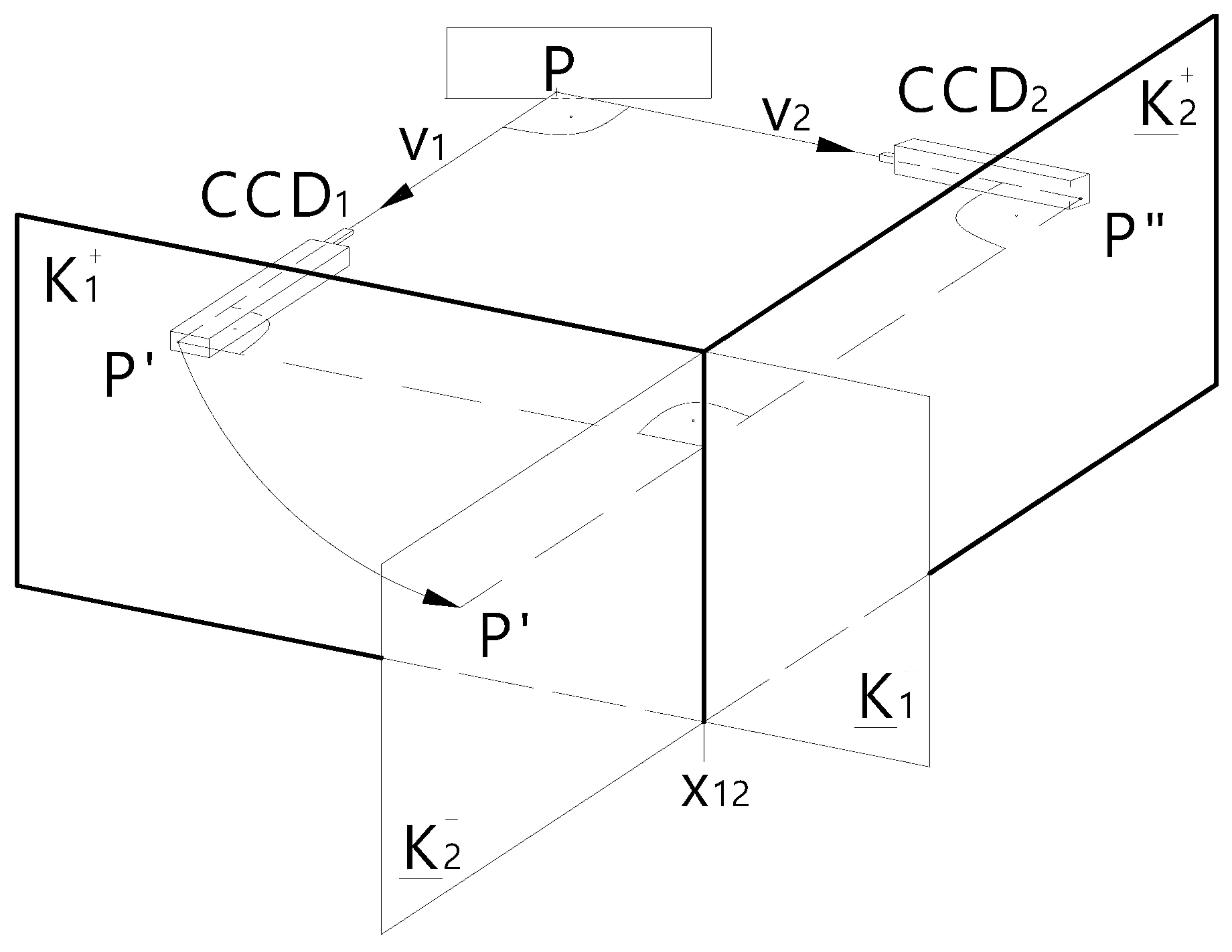
2. Method of ensuring the bijectivity of Monge's representation by defining the directions of the views
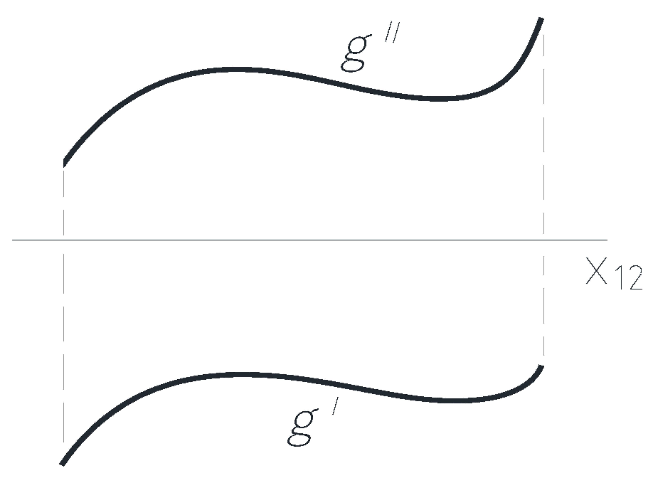
2.1. Examining the spatial curve
2.2. Correspondence between ordered orthogonal projections and real number triplets
2.2.1. Directed angles of the straight line
2.2.2. The relationship between the tripets of directed angles and the Monge projections
2.3. Application of the method
- The curve must be positioned in a fixed O[x, y, z] initial Cartesian coordinate system.
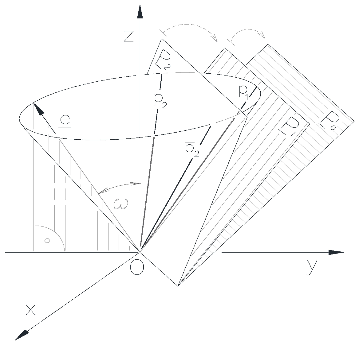
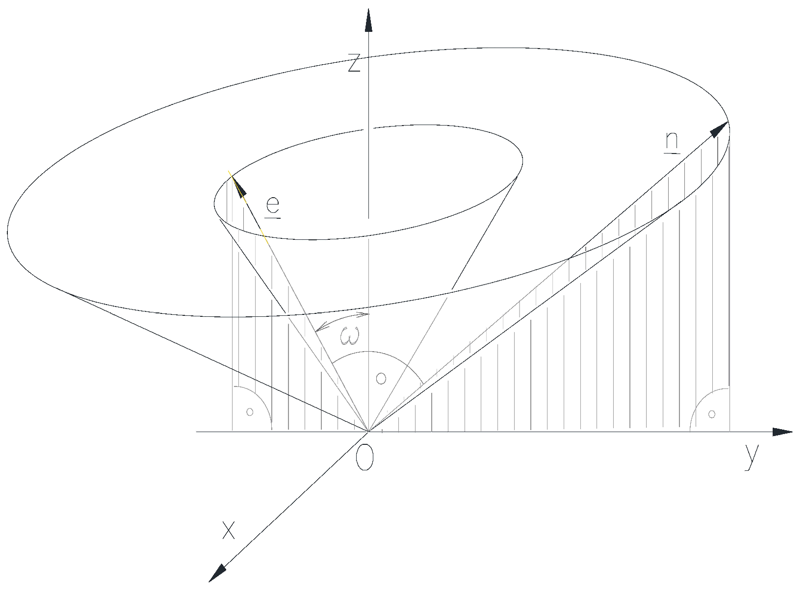
- The direction cone formed from the direction of the tangents of the curve must be determined, that is, the tangents of the curve must be moved parallel to themselves into a properly selected point of the z axis, such as the origin O.
- Examining the mutual position of the profile planes of the Monge projections and the directional cone, it is necessary to find the cases when they do not have a common line.
2.3.1. Procedure for the representation of a straight line
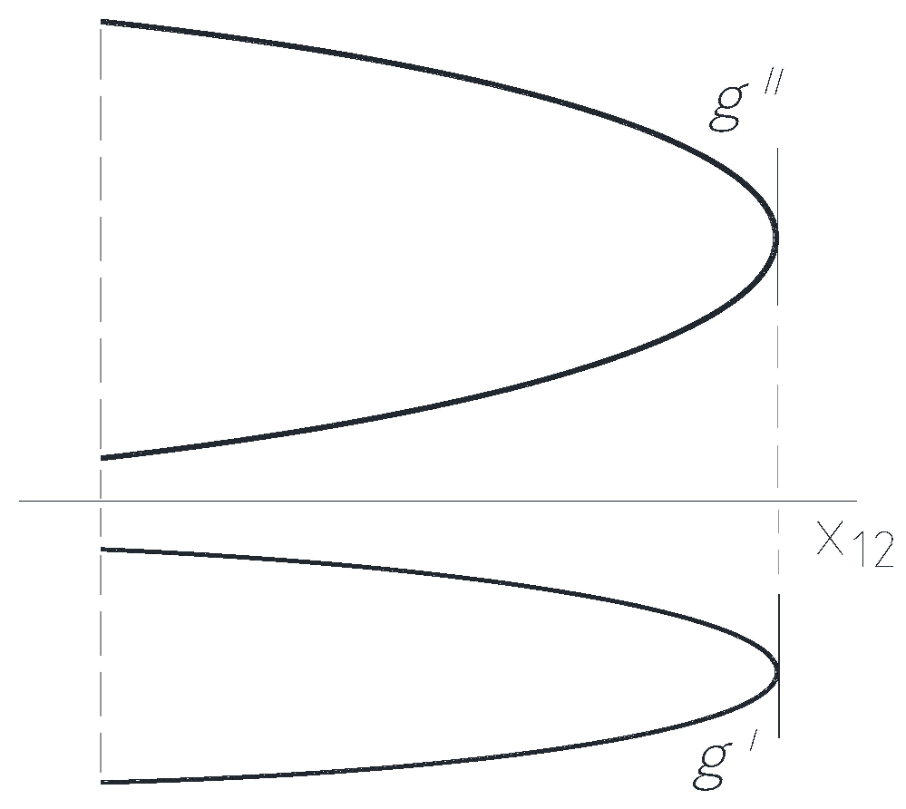
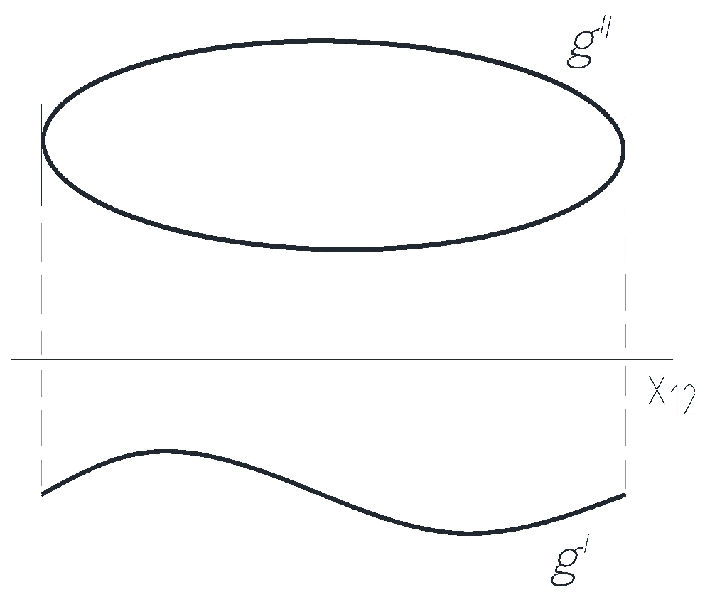
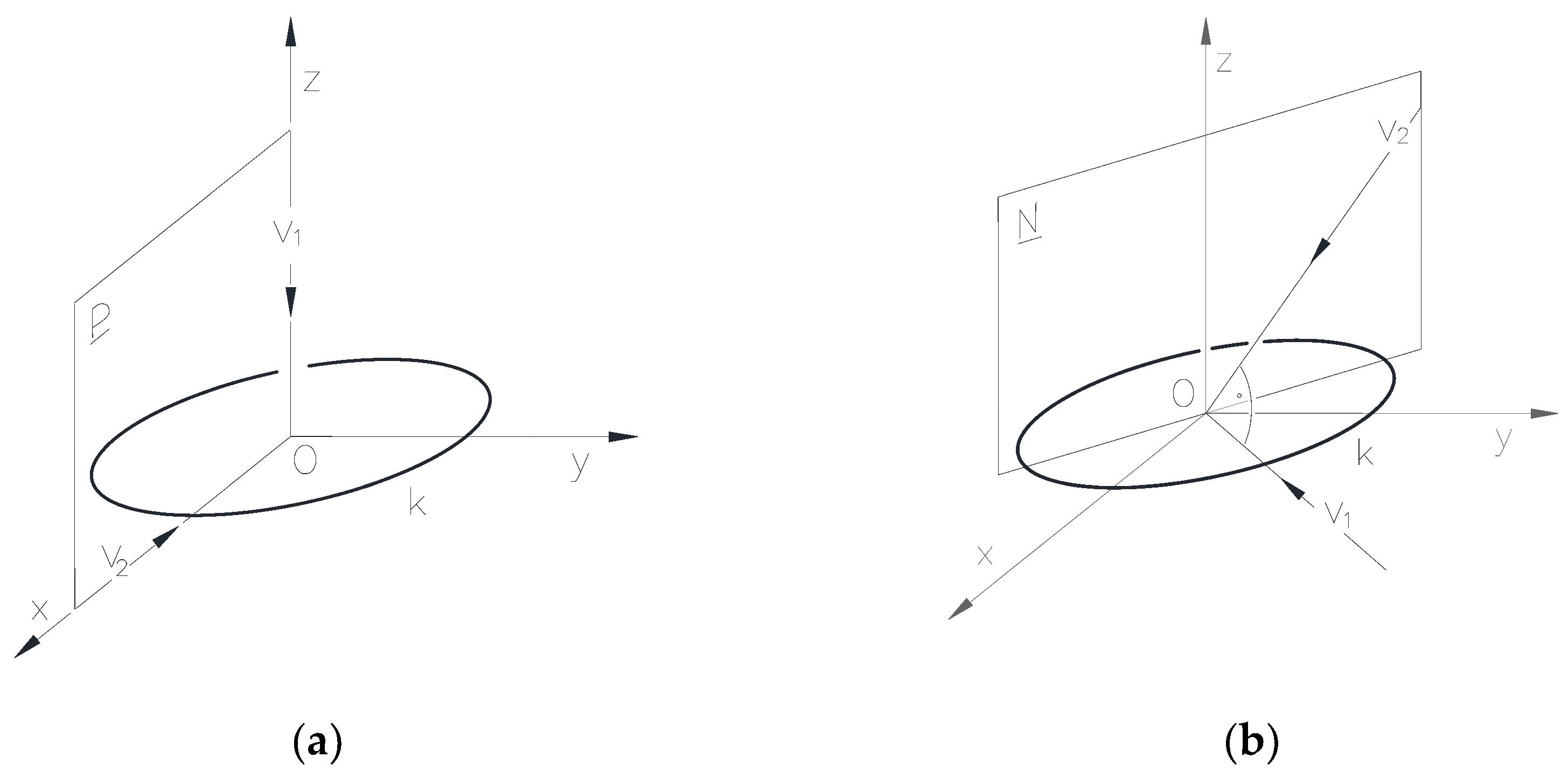
2.3.2. Procedure in the case of the circle representation
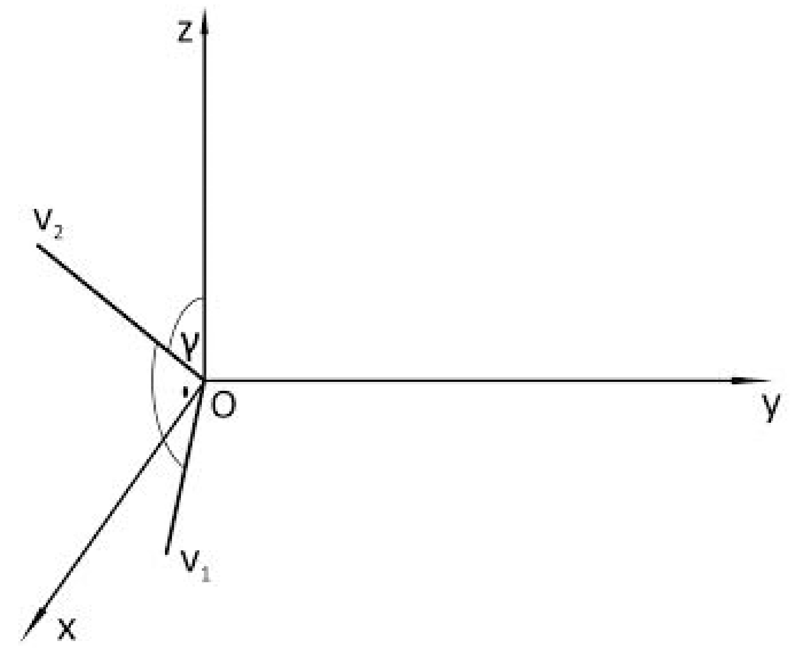
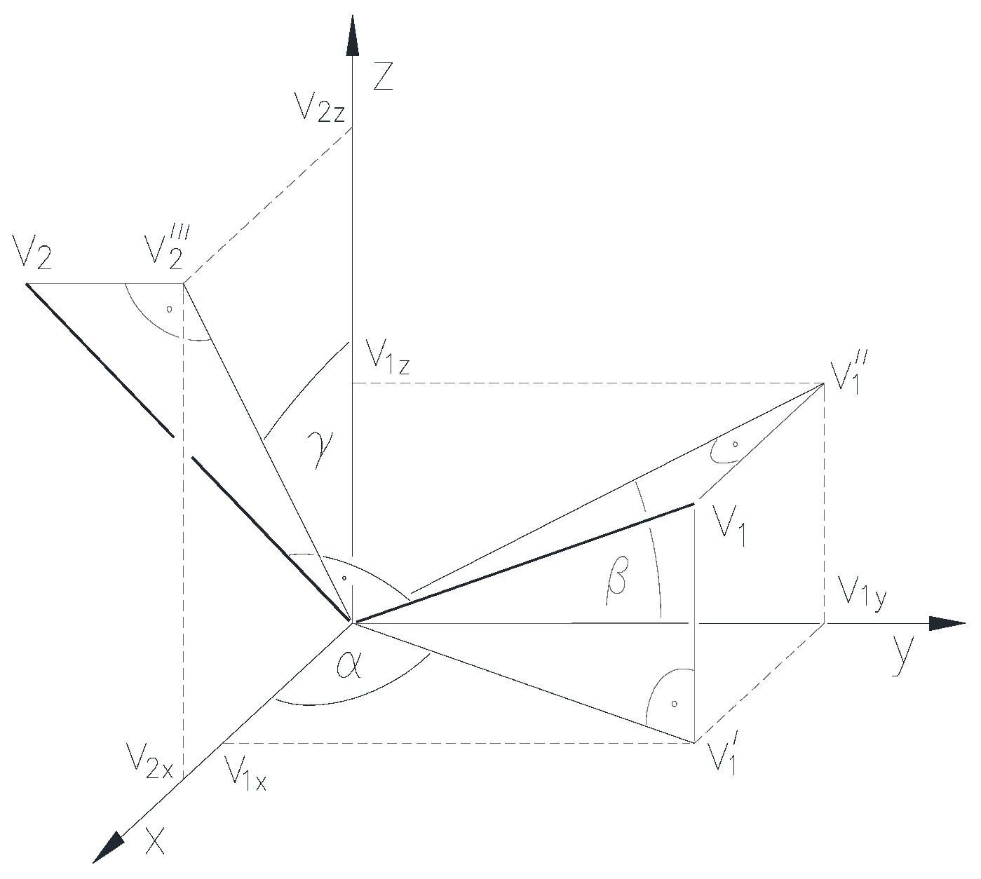
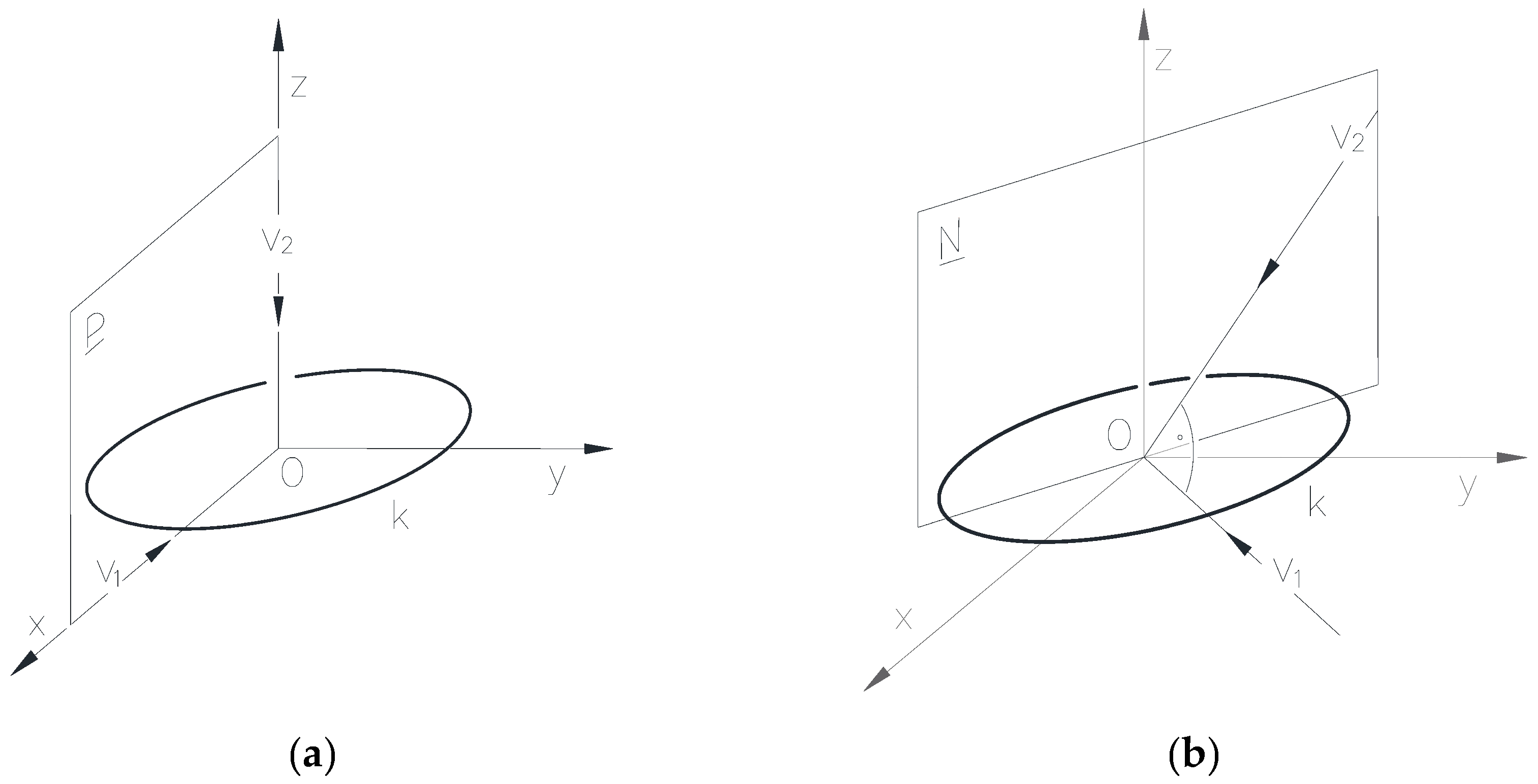
- Among the cases v2∈[xy] and v1∉[xy], the fulfillment of the v1∈z condition is determined by the directed angles α=0, β=π/2 and γ= π/2 as shown in Figure 13. a), so the circle can be clearly represented. If v2∈ [xy] and v1∉[xy] are fulfilled as shown in Figure 13.b), the representation of the given circle is bijective.
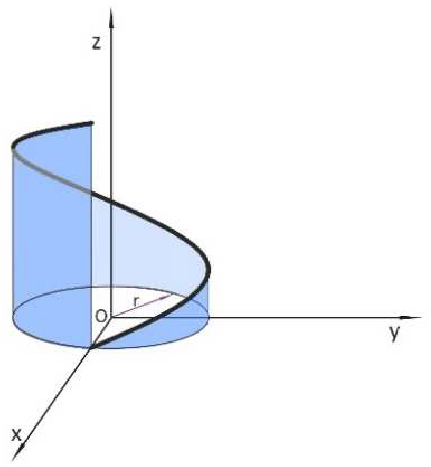
2.3.3. Presentation of the procedure during the representation of the helix
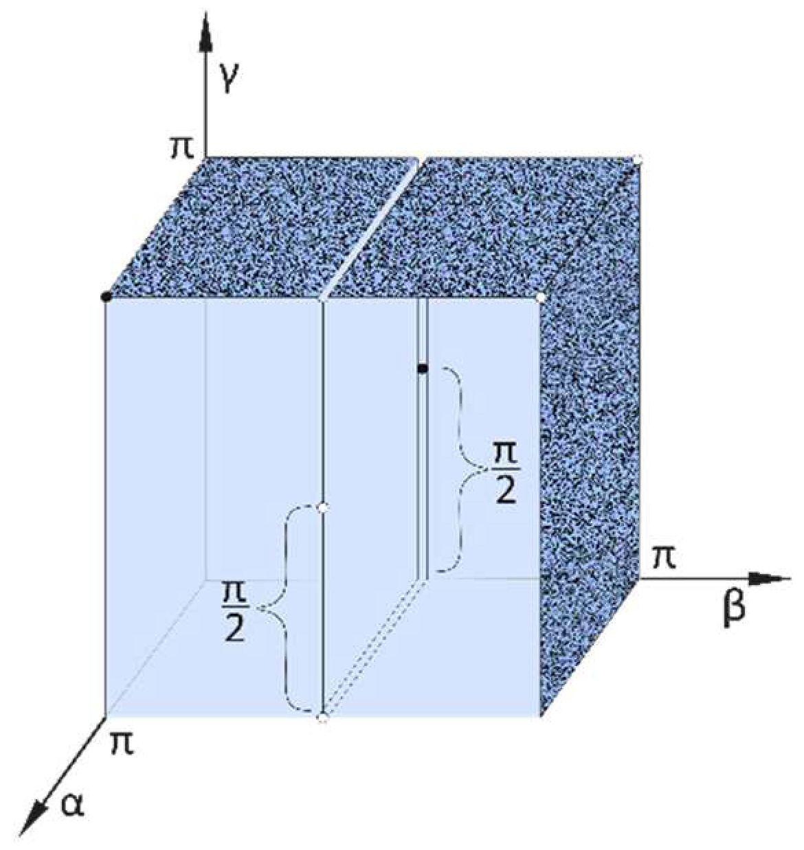
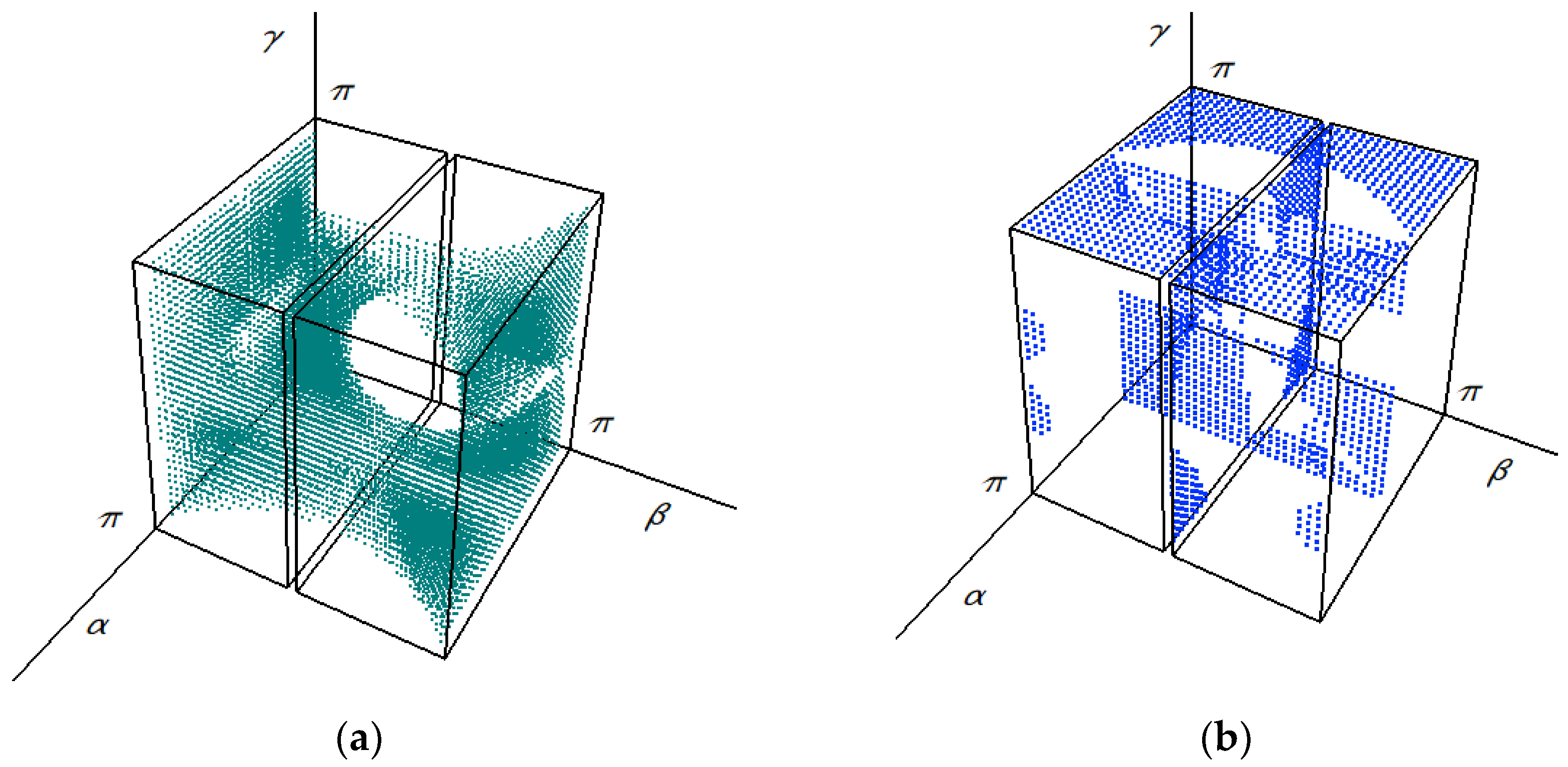
- α=π, β=0, γ=π, belong to the non-bijective subset of the Monge cuboid;
- α=0, β=π/2, γ=π/2, belong to the non-bijective subset of the Monge cuboid;
- 0<α<π, β=π, γ=π/2, always result a bijective Monge projection due to the condition 0<ω<π;
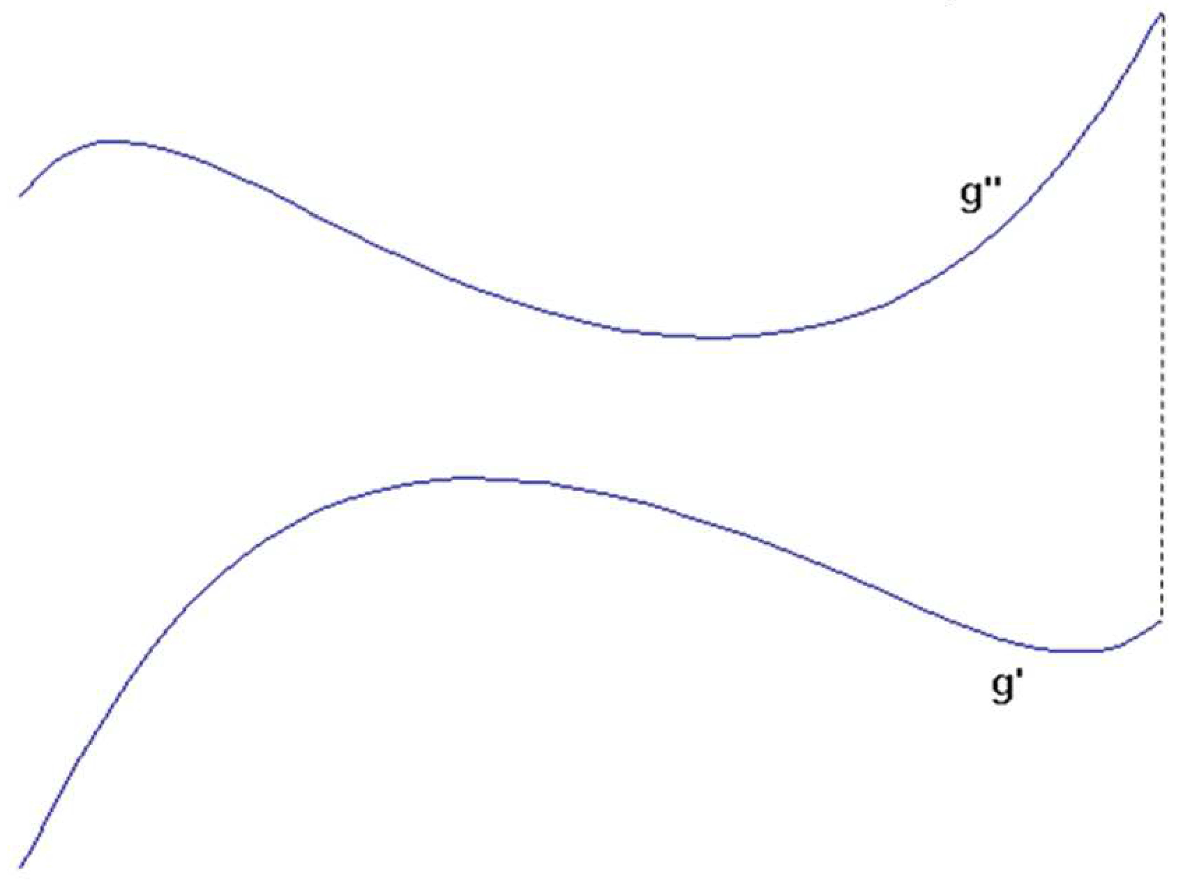
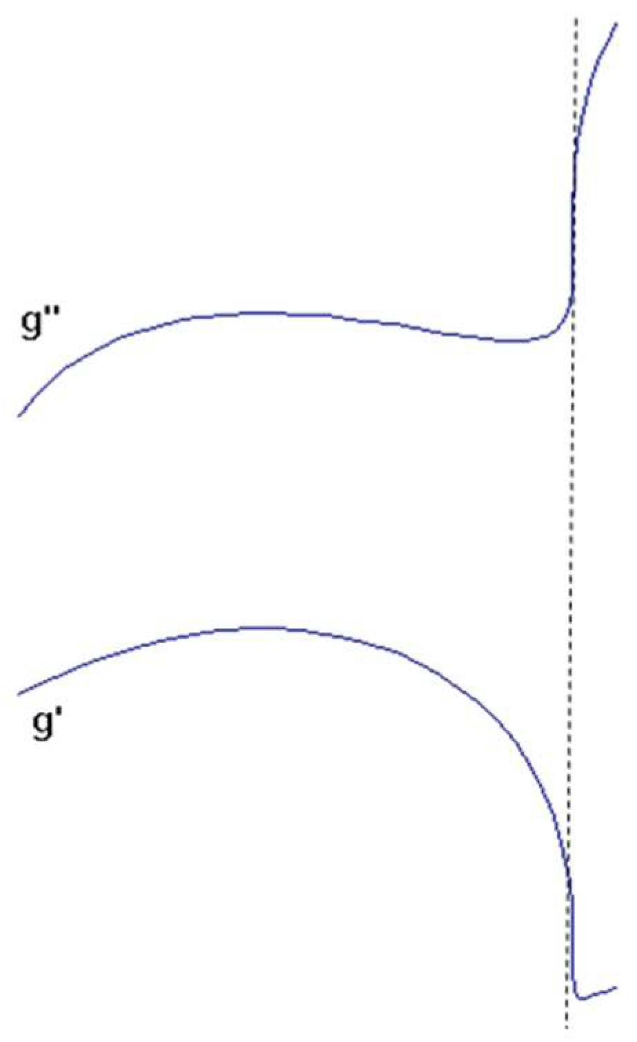
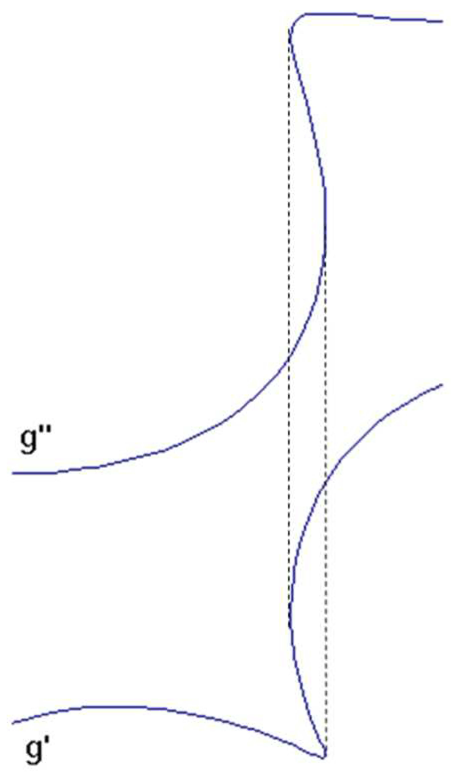
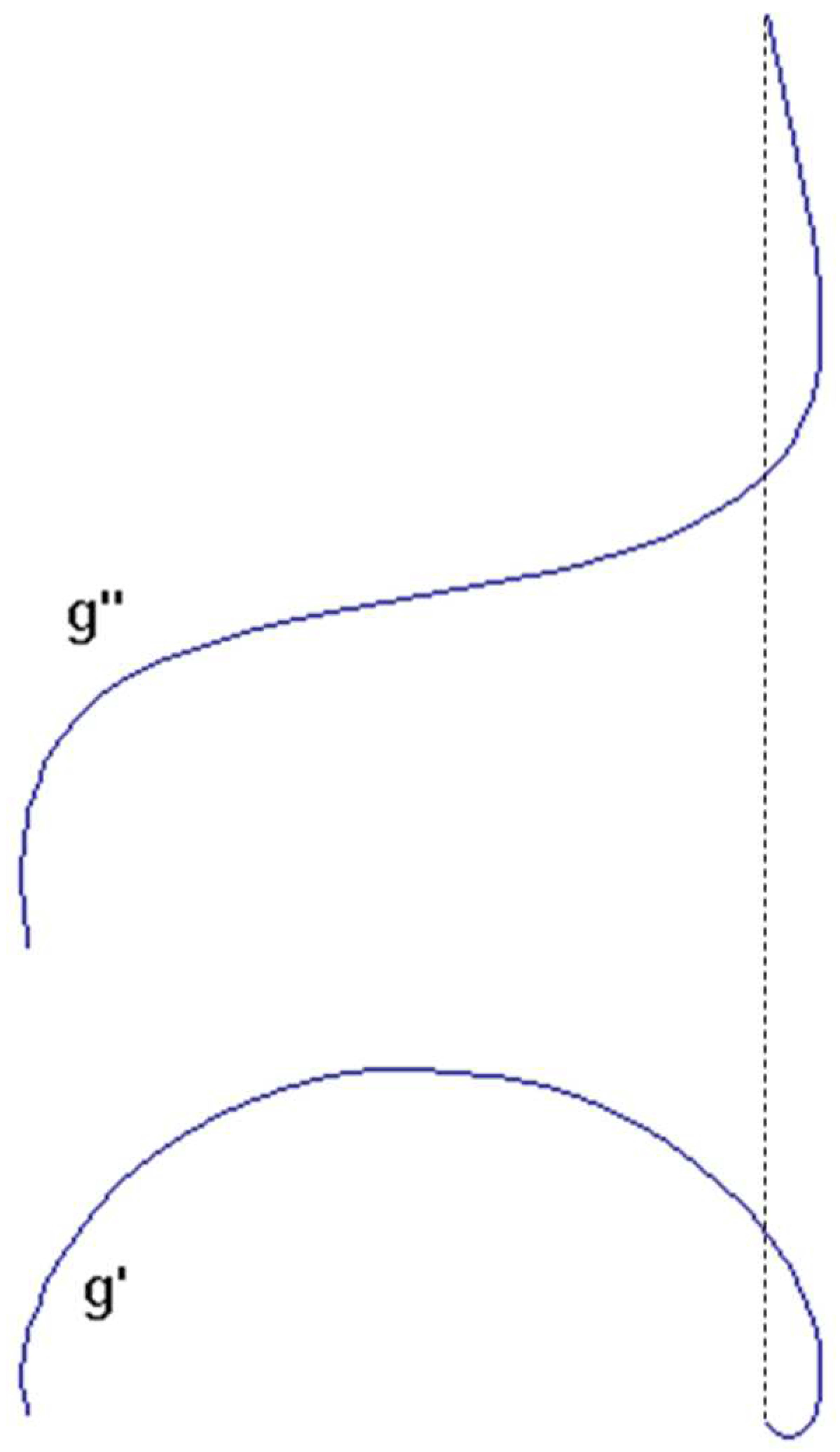
- 0<α<π, β=π, γ=π, always result a non-bijective Monge projections to the given helix, because of the circle shown second image;
- 0<α<π, β=π, 0<γ<π/2, π/2<γ<π, should be assumed in these cases, so that |v1|=1.
- α=π/2, 0<β<π/2, π/2<β<π, γ=π always results non-bijective Monge projections;
- 0<α<π/2, π/2<α<π, 0<β<π/2 ,π/2<β<π, γ=π, the v2x=0, and nx, nz,v1x, v1z ≠0.
- α=π/2, 0<β<π/2, π/2<β<π, γ=π/2, the v1x=0, and the v2∈x, so v2y, v2z=0.
- α=π/2, 0<β<π/2 ,π/2<β<π, 0<γ<π/2 π/2<γ<π the v1x=0. Since γ≠π/2, therefore v2∉[xy], so nx≠0, and since γ ≠ 0, π and the v2∉[yz], consequently nz≠0.
2.3.4. Procedure for a spatial curve representation
3. Result and application in mechanical engineering practice
4. Discussion
5. Conclusions
Funding
Acknowledgments
Conflicts of Interest
References
- Stachel, H. The status of today’s Descriptive Geometry related education (CAD/CG/DG) in Europe. In Proceedings of the Annual Meeting of JSGS, 40th anniversary of Japan Society for Graphic Science, 15-20, Tokyo, Japan, 2007. [CrossRef]
- Forgó, Z.; Tolvaly-Roșca, F.; Pásztor, J.; Kővári, A. Energy Consumption Evaluation of Active Tillage Machines Using Dynamic Modelling. Appl. Sci. 2021, 11, 6240. [CrossRef]
- Suzuki, K. Traditional Descriptive Geometry Education in the 3D-CAD/CG Era. Journal for Geometry and Graphics 2014, Volume 18, No. 2, 249–258. https://www.heldermann-verlag.de/jgg/jgg18/j18h2suzu.pdf.
- Tozzi, A.; Mariniello, L. Unusual Mathematical Approaches Untangle Nervous Dynamics. Biomedicines 2022, 10, 2581. [CrossRef]
- Guth, P. L.; Van Niekerk, A.; Grohmann, C. H.; Muller, J. P.; Hawker, L.; Florinsky, I. V.; Gesch, D.; Reuter, H. I.; Herrera-Cruz, V.; Riazanoff, S.; López-Vázquez, C.; Carabajal, C. C.; Albinet, C.; Strobl, P. Digital Elevation Models: Terminology and Definitions. Remote Sens. 2021, 13, 3581. [CrossRef]
- Szarvas, B.; Virág, Z. Seismic effects of rock blasting in the Erdőbénye andesite quarry. Multidisciplinary sciences 2021, 11, No 1, 159-169. [CrossRef]
- Miklós, R.; Lénárt, L.; Darabos, E.; Kovács, A.; Pelczéder, Á.; Szabó, N. P.; Szűcs, P. Karst water resources and their complex utilization in the Bükk Mountains, northeast Hungary: an assessment from a regional hydrogeological perspective. Hydrogeology Journal 2020, 28, 2159–2172. [CrossRef]
- Yin, Q.; Chen, Z.; Zheng, X.; Xu, Y.; Liu, T. Sliding Windows Method Based on Terrain Self-Similarity for Higher DEM Resolution in Flood Simulating Modeling. Remote Sens. 2021, 13, 3604. [CrossRef]
- Kundrák, J.; Nagy, A.; Markopoulos, A. P.; Karkalos, N. E. Investigation of surface roughness on face milled parts with round insert in planes parallel to the feed at various cutting speeds. Cutting & Tools in Technological System 2019, No 91, ISSN 2078-7405, 87-96. [CrossRef]
- Cepova, L.; Cep, R.; Chalko, L.; Dvorackova, S.; Trochta, M.; Rucki, M.; Beranek, L.; Mizera, O.; Chyshkala, V. The Effect of Cutting Tool Geometry on Surface Integrity: A Case Study of CBN Tools and the Inner Surface of Bearing Rings. Applied Sciences 2023, 13, 3543. [CrossRef]
- Cabezas, S.; Hegedűs, G.; Bencs, P. Transient heat convection analysis of a single rod in air cross-flow. Pollack Periodica 2023, 18, 23-28. [CrossRef]
- Cvetković, I. D.; Stojićević, M. D.; Stachel, H.; Milićević, R. G.; Popkonstantinović, B. D. The Man who Invented Descriptive Geometry. FME Transactions 2019, 47, (2):331-6. [CrossRef]
- Bucur, C.; Máté, M. Theoretical Peculiarities Regarding the Definition and Representation of the Rolling Surfaces for Chain Transmission. Procedia Eng. 2017, 181, 206–213. [CrossRef]
- Hervé, J.M. Théodore Olivier (1793–1853). Distinguished Figures in Mechanism and Machine Science, History of Mechanism and Machine Science 2007, 1, 295-318. [CrossRef]
- Glaeser, G.; Stachel, H. Kinematics—Geometry of Motion. In: Open Geometry: OpenGL® + Advanced Geometry 1999, 451, 229–267. [CrossRef]
- Attila Körei, A.; Szilágyi, Sz. Displaying Parametric Curves with Virtual and Physical Tools. The Teaching of Mathematics 2022, Vol. XXV, No. 2, 61–73. [CrossRef]
- Maláková, S.; Urbanský, M.; Fedorko, G.; Molnár, V.; Sivak, S. Design of Geometrical Parameters and Kinematical Characteristics of a Non-circular Gear Transmission for Given Parameters. Applied Sciences 2021, 11, 1000. [CrossRef]
- Bendefy A.; Horák P. Gear pair generation with the method of transposed lines of action. In Proceedings of the 14th International Design Conference, DESIGN 2016, Zagreb, Croatia, 16-19, May, 2016, 129-136. https://www.designsociety.org/publication/38822/GEAR+PAIR+GENERATION+WITH+THE+METHOD+OF+TRANSPOSED+LINES+OF+ACTION.
- Bendefy A.; Horák P. Cylindrical Gears with Changing Ratio. Periodica Polytechnica Mechanical Engineering 2017, 61, 130-134. [CrossRef]
- Benotsmane, R.; Dudás, L.; Kovács, G. Newly Elaborated Hybrid Algorithm for Optimization of Robot Arm’s Trajectory in Order to Increase Efficiency and Provide Sustainability in Production. Sustainability 2021, 13, 8193. [CrossRef]
- Balajti, Z. Development of the Manufacturing Geometry of Conical and Cylindrical Worms by Analyzing of Their Axoids. Manufacturing Technology 2020, 20, 3-10. [CrossRef]
- Güler, E. Generalized Helical Hypersurfaces Having Time-like Axis in Minkowski Spacetime. Universe, 2022, 8, 469. [CrossRef]
- Balajti, Z.; Mándy, Z. Proposed solution to eliminate pitch fluctuation in case of conical screw surface machining by apex adjustment. Procedia Manufacturing 2021, 55, 266-273. [CrossRef]
- Bonata, C. I.; Bolos, V. The mathematical model of generating kinematic for the worm face gear with modified geometry. Procedia Technology 2014, 12, 442 – 447. [CrossRef]
- Hogyai, N.; Máté, M.; Tolvaly-Roșca, F.; Drăgoi, M. V. Peculiarities of the Grinding Process of a Gear Hob Helical Rake Face. Acta Universitatis Sapientiae, Electrical and Mechanical Engineering, 2021, 13, 39-51. [CrossRef]
- Tolvaly-Roșca, F.; Forgó, Z.; Máté, M. Evaluation of a Mixed CAD Gear Modeling from Time and Precision Point of View. Procedia Technology 2015, 19, 28-33. https://creativecommons.org/licenses/by-nc-nd/4.0/.
- Ábrahám, Gy.; Wenzelné Gerőfy, K.; Antal, Á.; Kovács, G. Technical Optics, 1st ed.; Institute of Mechatronics, Optics, AndMechanical Engineering Informatics: Budapest University of Technology and Economics, Budapest, Hungary, 2015; p. 308. ISBN 978-963-313-202-9. https://mogi.bme.hu/TAMOP/muszaki_optika/index.html.
- Csoba, I.; Kunkli, R. Rendering algorithms for aberrated human vision simulation. Visual Computing for Industry, Biomedicine and Art 2023, 6, p. 5. [CrossRef]
- Prado-Velasco, M.; García-Ruesgas, L. Intersection and Flattening of Surfaces in 3D Models through Computer-Extended Descriptive Geometry (CeDG). Symmetry 2023, 15, 984. [CrossRef]
- Papp, G.; Papp, I.; Kunkli, R. Three-dimensional connection visualization based on tabular data. In Proceedings of the 8th IEEE International Conference on Cognitive Infocommunications (CogInfoCom), pp.: 289-290, Debrecen, Hungary, 11-14 Sept. 2017. https://scholar.google.com/scholar?as_q=Three-dimensional+connection+visualization+based+on+tabular+data&as_occt=title&hl=en&as_sdt=0%2C31.
- Ding, Z.; Liu, S.; Liao, L.; Zhang, L. A digital construction framework integrating building information modeling and reverse engineering technologies for renovation projects. Automation in Construction 2019, 102, 45–58. [CrossRef]
- Papp, I.; Zichar, M. 3D Modelling and Printing Interpreted in Terms of Cognitive Infocommunication. Cognitive Infocommunications, Theory and Applications Topics in Intelligent Engineering and Informatics 2019, 13. [CrossRef]
- Bartonek, D.; Buday, M. Problems of Creation and Usage of 3D Model of Structures and Theirs Possible Solution. Symmetry 2020, 12, 181. [CrossRef]
- Benardos, P.; Vosniakos, G. C. Removed material volume calculations in CNC milling by exploiting CAD functionality. International Journal of Computer Aided Engineering and Technology 2018, 10(5), 495-503. [CrossRef]
- Dudás, I.; Balajti, Z. Modelling and development for describing the bearing pattern of spiroid drives. Proceedings of the Sixth IASTED International Conference on ”Robotics and Applications, Cambridge, USA, Oct. 31. – Nov. 02. 2005., 203-208., ISBN 0-88986-521-3. https://www.actapress.com/Abstract.aspx?paperId=22994.
- Bodzás, S.; Békési, Z.; Kertész, J.; Szorcsik, T. The CAD Modelling Possibilities of Gear Pairs by Two Ways in the Mechanical Engineering Practice. International Journal of Engineering and Management Sciences 2021, 6(2), 205–219. [CrossRef]
- Kundrák, J.; Felhő, C.; Nagy, A. Analysis and Prediction of Roughness of Face Milled Surfaces using CAD Model. Manufacturing Technology 2022, 22 (5), 558-572. [CrossRef]
- Máté, M.; Tolvaly-Roșca, F.; Hodgyai, N.; Drăgoi, M.V. A new approach of defining the grinding wheel profile of the Gear Hob’s Rake Face. In Proceedings of the IEEE Joint 22nd International Symposium on Computational Intelligence and Informatics and 8th International Conference on Recent Achievements in Mechatronics, Automation, Computer Science and Robotics (CINTI-MACRo 2022), Budapest, Hungary, 21-22, November, 2022. [CrossRef]
- Hogyai, N.; Drăgoi, M. V.; Tolvaly-Roșca, F.; Máté, M. About the Grinding of Gear Hob’s Rake Face. Papers on Technical Science – International Scientific Series of the Transylvanian Museum Society, 2022, 16, 31-35. [CrossRef]
- Dudás, I. The Theory and Practice of Worm Gear Drives; Penton Press: London, UK, 2000.
- Olivier, Th. Theorie geometrique engrenager, Maurice Daumas, Paris, 1842. https://archive.org/details/thoriegomtrique01olivgoog.
- Balajti, Z. Development of Production Geometry of Kinematical Drive Pairs. PhD Dissertation, University of Miskolc, Miskolc, Hungary, 2007, p. 171. (In Hungarian) http://midra.uni-miskolc.hu/document/5519.
- Bodzás, S.: Manufacturing of spur gears having normal teeth on different pressure angles by module disc milling cutter. International Review of Applied Sciences and Engineering 2022, 13, 3, 321–334. [CrossRef]
- Tomori, Z. An Optimal Choice of Profile Shift Coefficients for Spur Gears. Machines 2021, 9, 106. [CrossRef]
- Meng, Q.; Zhao, Y.; Yang, Z. Curvature interference characteristic of conical worm gear. Forsch Ingenieurwes 2019, 83, 759–773. [CrossRef]
- Pavlenko, S.; Mascenik, J.; Krenicky, T. Mathematical Modeling of Drive and Dynamic Load of Teeth of Cylindrical Worm Gear. 2022, In Sustainable Management of Manufacturing Systems in Industry 4.0, 1st ed.; Editor 1, A., Editor 2, B., Eds.; Publisher: Publisher Location, Country, 2007; Volume 3, pp. 61-84. [CrossRef]
- Balajti, Z. Examination and adjustment of bearing pattern in case of helicoid drives. Procedia CIRP 2018, 77, 267–270, ISSN 2212-8271. https://www.sciencedirect.com/journal/procedia-cirp/vol/77/suppl/C.
- Hungarian Scientific Research Fund-OTKA No T026566 Theme manager Prof. Dr. Dr. h. c. Dudás, I. DSc. Development of CCD cameras systems to the area of machine industry. Miskolc; 2002.
- Balajti Z. Theoretical analysis and application of the Monge representation in engineering practice. Publisher: Gazdász Elasztik Ltd. University of Miskolc, Hungary, 2015, ISBN: 978-963-358-097-4, 101 p. https://www.researchgate.net/publication/372855431_A_Monge_abrazolas_elmeleti_elemzese_es_alkalmazasa_a_mernoki_gyakorlatban_Miskolc_2015_ISBN_978-963-358-097-4_101_o.
- Balajti, Z.; Dudás, I. The Monge Theorem and Its Application in Engineering Practice. International Journal of Advance in Manufturing Technolology, 2017, 91, 739–749. [CrossRef]
- Dudás, I.; Bányai, K. ; Bodzás, S. Finishing production of spiroid worm shaft by varied centre distance and by appling grinding wheel banking angle correction. International Review of Applied Sciences and Engineering 2016, (7) 13-19. https://akjournals.com/view/journals/1848/7/1/article-p13.xml.
- Dudás, L. Modelling and simulation of a new worm gear drive having point-like contact. Eng. Comput. 2013, 29, 251–272.
- Bodzás, S. Connection analysis of surfaces of conical worm, face gear and tool. PhD Dissertation, University of Miskolc, Miskolc, Hungary, 2016, p. 120. (In Hungarian) http://midra.uni-miskolc.hu/document/18016/11619.pdf.
- Mándy, Z. Intelligent manufacturing system and geometrically exact manufacture of the helicoid surfaces. PhD Dissertation, University of Miskolc, Miskolc, Hungary, 2022, p.105. (In Hungarian) Academic leader: Z. Balajti. Qualification: Summa cum laude. http://193.6.1.94:9080/JaDoX_Portlets/documents/document_40897_section_38553.pdf.
- Ábel, J. Computer based constructive geometric and analytical development of the manufacturing geometry of worm gear drive pairs. PhD Dissertation, University of Miskolc, Miskolc, Hungary, 2023, p. 99. (In Hungarian) Academic leader: Z. Balajti. Qualification: Summa cum laude. http://midra.uni-miskolc.hu/document/43049/41118.pdf.
- Balajti, Z. Determination of Undercutting Avoidance for Designing the Production Technology of Worm Gear Drives with a Curved Profile. Machines 2023, 11, 56. [CrossRef]
- Stanojevic, M.; Stojanovic, B.; Bankovic, N. Analysis of Influential Geometric Parameters on the Safety Factor on the Sides of Gear Pairs in the Gearbox Using Taguchi Method. In Proceedings of the 11th international conference on Quality System Condition for Successful Business and Competitiveness, Kopaonik, Serbia, 17-19 May 2023. https://www.researchgate.net/publication/373160923_ANALYSIS_OF_INFLUENTIAL_GEOMETRIC_PARAMETERS_ON_THE_SAFETY_FATOR_ON_THE_.
- 58. SIDES_OF_GEAR_PAIRS_IN_THE_GEARBOX_USING_TAGUCHI_METHOD.
- Gao, W.; Haitjema, H.; Fang, F.Z.; Leach, R.K.; Cheung, C.F.; Savio, E.; Linares, J.M. On-machine and in-process surface metrology for precision manufacturing. CIRP Ann. 2019, 68, 843–866.
- Jiao, F.; Liu, L.; Cheng, W.; Li, C.; Zhang, X. Review of optical measurement techniques for measuring three-dimensional topography of inner-wall-shaped parts. Measurement 2022, 202, 111794.
- Lu, W.; Chen, S.; Zhang, K.; Zhai, D. Characterization of diffractive relief structures over large areas by stitching interference microscopic topography. Measurement 2022, 202, 111850.
- Guo, J.; Zhai, D.; Lu, W.; Chen, S. Topography measurement of helical grooves on a hemisphere based on stitching interference microscopy. Opt. Laser Technol. 2022, 152, 108133.
- Ying, R.; Cui, Y.; Huang, J.; Liang, D.; Wang, Y. Precise measurement of surface topography with microstructures based on differential confocal and spiral scanning. Measurement 2021, 184, 110004.
- Leksycki, K.; Królczyk, J.B. Comparative assessment of the surface topography for different optical profilometry techniques after dry turning of Ti6Al4V titanium alloy. Measurement 2021, 169, 108378.
- Schmidt, J.; Thorenz, B.; Schreiner, F.; Döpper, F. Comparison of areal and profile surface measurement methods for evaluating surface properties of machined components. Procedia CIRP 2021, 102, 459–464.
- Svetlik, J.; Baron, P.; Dobransky, J.; Kocisko, M. Implementation of computer system for support of technological preparation of production for technologies of surface processing. In Applied Mechanics and Materials, Proceedings of the ROBTEP 2014: 13th International Conference on Industrial, Service and Humanoid Robotics, High Tatras, Slovakia, 15–17 May 2014; Trans Tech Publications Ltd.: Zurich, Switzerland, 2014; Volume 613, pp. 418–425. ISBN 978-303835202-0.
- Stamenović, B.; Stoimenov, M.; Popkonstantinovic, B.; Jeli, Z. Presses for Designing Flexible Pipes Correction, Finite Elements Analysis and Prepearing “G” Code for Construction Elements of Plasma Cutter. In Proceedings of the 4th International Scientific Conference on Geometry and Graphics moNGeometrija, Vlasina, Serbia, 20-22, June, 2014, 141-156. http://mongeometrija.com/konferencije/mongeometrija-2014.
- Simon, V. Multiobjective optimization of hypoid gears to improve operating characteristics. Mechanism and Machine Theory, 2019, 146, 905-914. [CrossRef]
- Jakab, M.; Ali, O.I.; Gyurika, I.G.; Korim, T.; Telegdi, J. The Tribological Behavior of TiN/TiC CVD Coatings under Dry Sliding Conditions against Zirconia and Steel Counterparts. Coatings 2023, 13, 832. [CrossRef]
- Hegedűs, G. Manufacturing Parameters Determination on Ball Nut Grinding. Design of Machines and Structures, 2015, 5, 1, 33-38. HU ISSN 2064-7522 online, https://www.uni-miskolc.hu/dms/docs/dms_vol5_nr1_2015.pdf.
- Dóka T.; Horák P. An Approach to Creating a Simple Digital Twin for Optimizing a Small Electric Concept Vehicle Drivetrain. In Proceedings of the 34th International ECMS Conference on Modelling and Simulation, European Council for Modelling and Simulation (ECMS), 9-12, June, 2020, 328-333. http://doi.org/10.7148/2020.
- Várkuli, M.; Bognár, G.; Szente, J. Determination of Tooth Surface Points on Bevel Gears for Checking on a Coordinate Measuring Machine. Design of Machines and Structures, 2023, 13, 1, 131–139. [CrossRef]
- Bihari, Z.; Szente, J. Determination of ideal curve having constant wedge angle for roller freewheels. Design of Machines and Structures, 2012, 2, 1, 15-24. https://www.uni-miskolc.hu/dms/docs/dms_vol2_nr1_2012_contents.pdf.
- Bercsey, T.; Horák, P. Calculation of the Efficiency of ZTA-Type Worm Gear Drives on the Base of The Ethd Lubrication Theory in Proceedings of the 5th International Meeting of the Carpathian Region Specialists in the Field of Gears, Bai Mare, Romania, 21, May, 2004, 34-38. https://www.researchgate.net/publication/237236853_5th_INTERNATIONAL_MEETING_OF_THE_CARPATHIAN_REGION_SPECIALISTS_IN_THE_FIELD_OF_GEARS_CALCULATION_OF_THE_EFFICIENCY_OF_ZTA-TYPE_WORM_GEAR_DRIVES_ON_THE_BASE_OF_THE_ETHD_LUBRICATION_THEORY.
- Jeli, Z.; Komatin, M.; Popkonstantinovic, B.; Regodic, M. Usage of modern graphical presentations in development of technical systems. In Proceedings of the 3th International Conference moNGeometrija, Novi Sad, Serbia, 21-24, June, 2012, pp. 553-564. ISBN 978-86-7892-405-7. https://mongeometrija.com/media/mongeometrija/2012/MoNGeometrija_2012_Zbornik.pdf.
- Popkonstantinovic, B.; Stojicevic, M.; Jeli, Z.; Obradovic, M.; Dragos-Laurentiu, P.: Simulation and Motion Study of Mechanical Integrator 3D Model. FME Transactions, 2019, 47, 2, 299-303. https://www.mas.bg.ac.rs/_media/istrazivanje/fme/vol47/2/12_b_popkonstantinovic_et_al.pdf.
- Máté, M.; Hollanda, D.; Tolvaly-Roşca, F.; Forgó, Z.; Egyed-Faluvégi, E. Synthesis of a Profile Errorless Involute Shaper Cutter with Cylindrical Rake Face. In Proceedings of the 2019 IEEE 19th International Symposium on Computational Intelligence and Informatics and 7th IEEE International Conference on Recent Achievements in Mechatronics, Automation, Computer Sciences and Robotics (CINTI-MACRo), Szeged, Hungary, 14-16 November 2019; pp. 71–78. [CrossRef]
- Máté, M.; Hollanda, D. Numerical Evaluation of the Shaper Cutter with Cylindrical Rake Face. Papers on Technical Science, 2020, 12. 55-62. ISSN 2601-5773. [CrossRef]
- Hodgyai, N.; Tolvaly-Roșca, F.; Máté, M. The Conditions of Undercut by Shaping Using a Rounded Profile Gear Shaper Cutter. Pap. Tech. Sci. Tech. Sci. Dep. Transylv. Mus.-Soc. 2021, 14, 30–36. (In Romania).
- Kawasaki, K.; Tsuji, I. Manufacturing Method for Large Cylindrical Worm Gear Set of ISO Type I on Universal CNC Machine Tools. J. Manuf. Mater. Process. 2023, 7, 53. [CrossRef]
- Karpuschewski, B.; Kundrák, J.; Felhő, C.; Varga, G.; Sztankovics, I.; Makkai, T.; Borysenko, D. Preliminary Investigation for the Effect of Cutting Tool Edge Geometry in High-Feed Face Milling. In Proceedings of the Vehicle and Automotive Engineering 2: Lecture Notes in Mechanical Engineering, 241-245, Miskolc, Hungary, 9, May, 2018. https://link.springer.com/chapter/10.1007/978-3-319-75677-6_20.
- Kuznetsov, V.; Smolin, I.; Skorobogatov, A.; Akhmetov, A. Finite Element Simulation and Experimental Investigation of Nanostructuring Burnishing AISI 52100 Steel Using an Inclined Flat Cylindrical Tool. Appl. Sci. 2023, 13, 5324. [CrossRef]
- Gál, V.; Lukács, Z. Effect of Cooling Channels to the Press Hardening Tools Temperature. In Proceedings of the Vehicle and Automotive Engineering 3: Lecture Notes in Mechanical Engineering, 312-320, Miskolc, Hungary, 25, November, 2020. [CrossRef]
- Varga, G.; Balajti, Z.; Dudás, I. Advantages of CCD Camera Measurements for Profile and Wear of Cutting Tools. Journal of Physics Institute of Physics Publishing in London, 2005, Conference Series 13, 159-162. [CrossRef]

Disclaimer/Publisher’s Note: The statements, opinions and data contained in all publications are solely those of the individual author(s) and contributor(s) and not of MDPI and/or the editor(s). MDPI and/or the editor(s) disclaim responsibility for any injury to people or property resulting from any ideas, methods, instructions or products referred to in the content. |
© 2023 by the authors. Licensee MDPI, Basel, Switzerland. This article is an open access article distributed under the terms and conditions of the Creative Commons Attribution (CC BY) license (http://creativecommons.org/licenses/by/4.0/).


