Preprint
Article

Estimating the Inertia Tensor Components of an Asymmetrical Spacecraft When Removing It from the Operational Orbit at the End of Its Active Life

Altmetrics

Downloads

78

Views

33

Comments

0

A peer-reviewed article of this preprint also exists.

Submitted:

05 November 2023

Posted:

06 November 2023

You are already at the latest version

Alerts
Abstract
The paper presents a method for estimating the inertia tensor components of a spacecraft that has expired its active life using measurement data of the Earth's magnetic field induction vector components. The implementation of this estimation method is supposed to be carried out when cleaning up space debris in the form of a clapped-out spacecraft with the help of a space tug. It is assumed that a three-component magnetometer and a transmitting device are attached on space debris. With the help of this measuring system, the parameters for the rotational motion of space debris are estimated. Then the known controlled action from the space tug is transferred to the space debris. Next, measurements for the rotational motion parameters are carried out once again. Based on the available measurement data and parameters of the controlled action, the space debris inertia tensor components are estimated. It is assumed that the measurements of the Earth's magnetic field induction vector components are made in a coordinate system which axes are parallel to the corresponding axes of the main body axis system. Such an estimation makes it possible to effectively solve the problem of cleaning up space debris, to calculate the costs of the space tug working body and the parameters of the space debris removal orbit. Examples of numerical simulation using the measurement data of the Earth's magnetic field induction vector components on the Aist-2D small spacecraft are given. The results of the work can be used in the development and implementation of missions to clean up space debris in the form of clapped-out spacecraft.
Keywords: 
Subject: Computer Science and Mathematics  -   Applied Mathematics

1. Introduction

Nowadays, various projects are being developed to clean up space debris from near-Earth space. This issue was first raised at UN meetings in the early 1980s. Even then it became clear that the active use of near-Earth space would create the problem of its cleaning from space debris of terrestrial origin [1, 2]. Space debris poses a serious threat to the safe operation of unmanned and manned spacecraft in near-Earth orbit. Due to the threat of collision with space debris maneuvers have become a common practice in the operation of modern spacecraft [3, 4]. All experts note that the number of launches of small spacecraft will increase significantly in the future [5].
Therefore, in the opinion of many authors, nowadays it is necessary to design spacecraft with systems for removing it from orbit at the end of its active life [6].
Various concepts have been developed for the removal of space debris from near-Earth orbits. The authors of [7] believe that the standard propulsion system of the spacecraft and the remnants of the working fluid can be used for removal. In this case, it is not necessary to design a separate system that removes the spacecraft at the end of its active life. However, this method can be used for oriented flight of the spacecraft with a full-fledged motion control system. The use of executive bodies that do not require the expenditure of working fluid makes this method inefficient.
The work [8] considers Drag Augmentation Systems (DAS). It is a space sail [9]. It unfolds at the end of the spacecraft active life. This sail contributes to the removal of the spacecraft from orbit due to the aerodynamic drag increase. This method involves the development of a separate system for transporting and unfolding a sail and is applicable mainly in low near-Earth orbits. For high orbits, the spacecraft deorbit time can be significant. Modern materials of such a sail have high stress-strain properties and have a low specific gravity. Therefore, the increase in the mass parameters of a small spacecraft when using such a system will be insignificant.
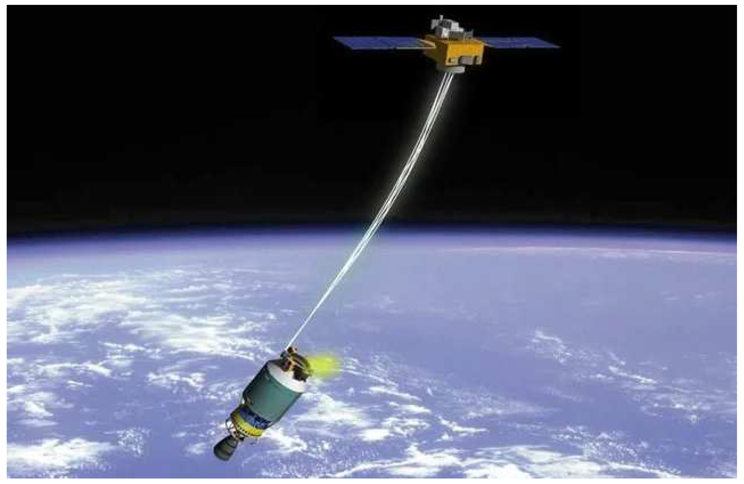
The review [10] presents a comparative analysis of four different methods of removing spacecraft from low near-Earth orbits at the end of their active life. Two active devices are considered: classical rocket and electric motors, and two passive technologies are considered: drag augmentation devices and electrodynamic cables [10]. The authors of [10] believe that, other things being equal, for an initial height of 850 km, cables are approximately one and two orders of magnitude lighter than active devices and drag augmentation devices, respectively. In this case, special attention is paid to electrodynamic cables, according to the results of the FP7/Space BETs project [10]. The superiority of ribbon cables over round and wire cables in terms of deorbit efficiency is substantiated, as well as the importance of the optimal choice for the length, width and thickness of a ribbon cable depending on the spacecraft mass and its initial orbit [10]. Figure 1 shows a diagram of transporting space debris by a cable using a space tug [11].
The prospect of using tether systems is noted by many researchers, for example, [12,13,14,15]. If it is possible to design and install systems for deorbiting the spacecraft when creating new space technology, then the task of cleaning up existing space debris leaves significantly fewer options for its solution. Therefore, one of the promising options for such cleaning is the use of a space tug in combination with a tether system for transporting space debris.
At the same time, methods of non-contact debris removal are actively developed, for example, using a laser system [16]. The authors of [16] propose to create a space laser facility to protect orbital stations from space debris. Based on the results of numerical simulation, a design for a space-based laser system was proposed in [16]. The developed laser system can effectively deal with space debris ranging in size from 1 to 10 cm. However, this method is more suitable for protecting operating space objects than for cleaning up space debris.
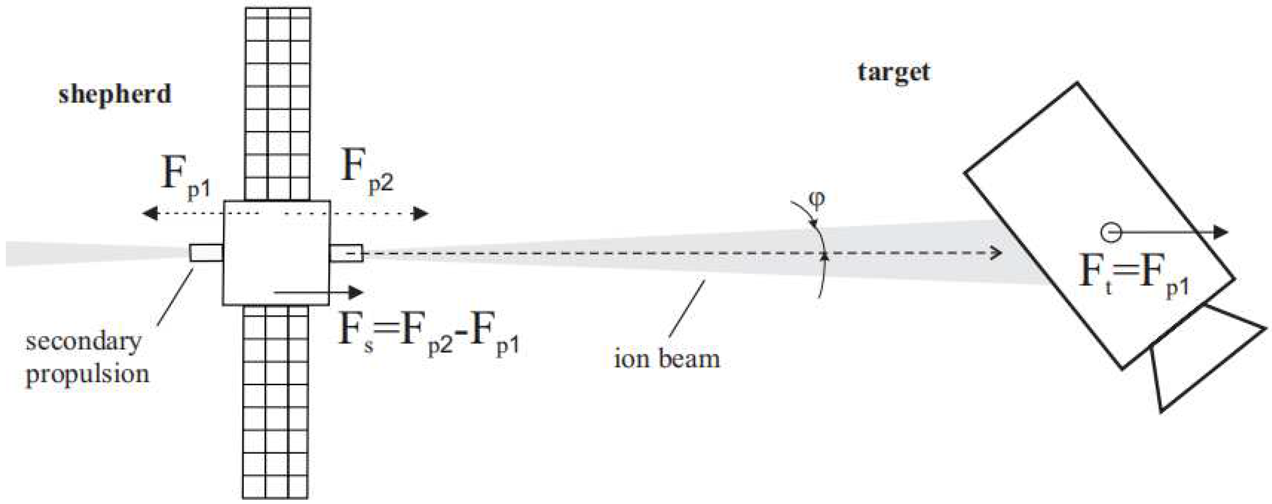
The work [17] contains a detailed review and comparison of existing technical solutions and approaches to space debris removal. Contactless transport systems are considered as a promising direction in the creation of safe and reliable space debris removal systems. One of the active influences on space debris is the use of an ion beam [17, 18]. The work [18] presents a scheme of the ion beam impact on space debris and analyzes the parameters for the impact that is necessary to successfully solve the problem of its removal (Figure 2) [18]. In [19], a multipath scheme was proposed and control laws for impulse motors were developed.
For effective contact (by tether systems) and contactless (by ion beams) cleaning of space debris in the form of spacecraft that have exhausted their active life, it is necessary to know the inertial-mass parameters of these spacecraft. Therefore, the problem of estimating the inertial-mass parameters of space debris, as well as the parameters of its rotational motion in absolute space and relative to the space tug, arises. This problem was considered not only in the context of the space debris problem in [11, 20-22]. In [20], the difficulties of estimating the inertia tensor of a captured object are noted in the case when the connection between the space tug and the debris is not rigid, for example, when using a tether system.
In [20], the components of the space debris inertia tensor are estimated using various Kalman filters by measuring the rotation velocity of space debris. The cases of a cable stretched all the time and a cable subject to frequent weakening are considered. A good estimation quality is shown if the cable tension and the cable attachment point are known [20]. However, in some cases, the authors of [20] note a large dispersion of the obtained estimations.
In [21], a system analysis for the influence of errors in measuring the parameters of the space debris rotational motion on the accuracy of estimating its inertial-mass parameters by the traditional method was carried out. To improve the estimation accuracy, the authors of [21] proposed a modification for the estimation equations by including the data on the contact force of the space tug impact on space debris.
In [22], it was proposed to use a nanosatellite as a data measurement system for estimating the parameters of the rotational motion of space debris. This satellite must dock with space debris and move with it as a single body. However, docking issues are not discussed.
In the general formulation, the solution of the problem of estimating the inertial-mass parameters for space debris of arbitrary shape moving arbitrarily in outer space is quite complicated. The possibility of attaching several measuring instruments on different parts of space debris, and the possibility of monitoring the relative position of these instruments, taking into account errors, will expand the range of application of the proposed method for estimating the inertial-mass parameters. However, technically it is not easy to solve this problem.
This work makes the following contribution:
1) a method for estimating the inertial-mass parameters for space debris and the parameters of its rotational motion by attaching elements of the data-measuring system on a space debris object is proposed;
2) the simulation is carried out for a particular case of attaching measuring instruments on a space debris object;
3) the results of numerical simulation for a particular case with an estimation of inertial-mass parameters for the Aist-2D small spacecraft are presented;
4) the analysis of the obtained results was carried out and recommendations for its use were given.

2. Problem formulation.

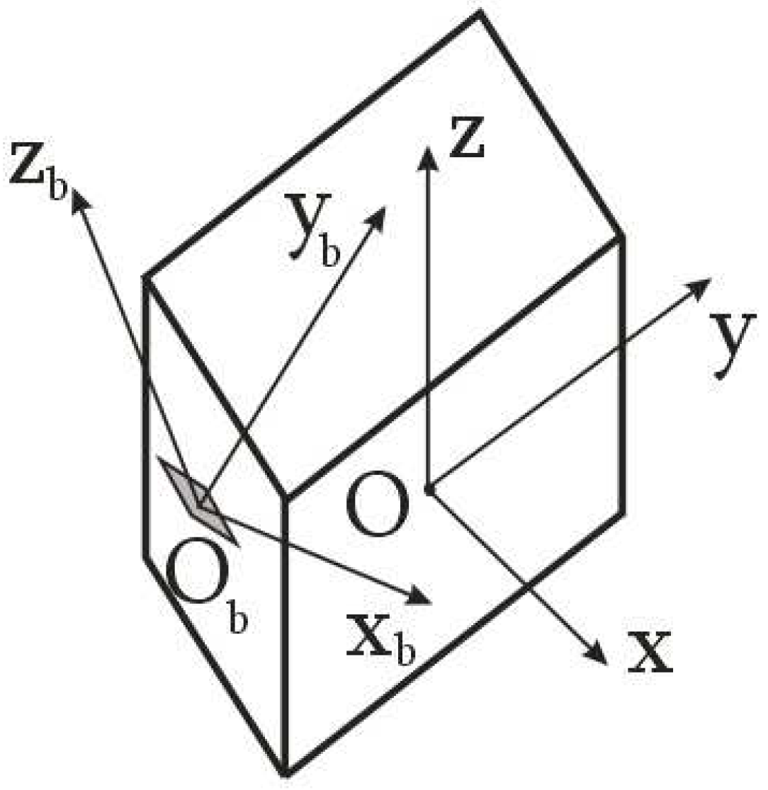
Let us consider the problem of estimating the inertial-mass parameters for a space debris object in the general formulation within the framework of the proposed approach of attaching the measuring equipment - a magnetometer - on it. Let us assume that a three-component magnetometer with a data-transmitting device has been attached to the space debris object. In this case, using the measurements of the Earth's magnetic field induction vector, it is possible to estimate the components of the angular velocity vector of space debris in the magnetometer's structural coordinate system (Figure 3).
To obtain a correct estimation for the angular velocity vector, it is proposed in [23] to use the derivative of the Earth's magnetic field induction vector components:
ω k = B ˙ k × B ˙ k 1 Δ t k | B ˙ k | 2 ,
where B ˙ k ( B ˙ x k ,    B ˙ y k ,    B ˙ z k ) and B ˙ k 1 ( B ˙ x k 1 ,    B ˙ y k 1 ,    B ˙ z k 1 ) are the derivatives of the Earth's magnetic field induction vector components and its components in the magnetometer's structural coordinate system (Figure 3) for the k-th and k-1-th measurements, respectively; Δ t k = t k t k 1 is the time interval between k-th and k-1-st measurements.
Let us represent the vector equation (1) in the axes of the magnetometer's structural coordinate system (Figure 3):
{ ω x k = B ˙ y k B ˙ z k 1 B ˙ z k B ˙ y k 1 Δ t k ( B ˙ x k 2 + B ˙ y k 2 + B ˙ z k 2 ) ; ω y k = B ˙ z k B ˙ x k 1 B ˙ x k B ˙ z k 1 Δ t k ( B ˙ x k 2 + B ˙ y k 2 + B ˙ z k 2 ) ; ω z k = B ˙ x k B ˙ y k 1 B ˙ y k B ˙ x k 1 Δ t k ( B ˙ x k 2 + B ˙ y k 2 + B ˙ z k 2 ) .
Then, with an arbitrary location of the axes of the magnetometer's structural coordinate system relative to the main body axis system of the space debris object, the Euler dynamic equations in the magnetometer's structural coordinate system will have the form [24]:
{ I x x ω ˙ x k I x y ω ˙ y k I x z ω ˙ z k + ω y k ( I z z ω z k I x z ω x k I y z ω y k ) ω z k ( I y y ω y k I x y ω x k I y z ω z k ) = M x I y y ω ˙ y k I x y ω ˙ x k I y z ω ˙ z k + ω z k ( I x x ω x k I x y ω y k I x z ω z k ) ω x k ( I z z ω z k I x z ω x k I y z ω y k ) = M y I z z ω ˙ z k I x z ω ˙ x k I y z ω ˙ y k + ω x k ( I y y ω y k I x y ω x k I y z ω z k ) ω y k ( I x x ω x k I x y ω y k I x z ω z k ) = M z ,
where M ( M x ,    M y ,    M z ) is the main vector of external moments acting on the space debris object; I ^ = [ I x x    I x y    I x z I x y    I y y    I y z I x z    I y z    I z z ] is the symmetrical inertia tensor in the magnetometer's structural coordinate system; ω ˙ k ( ω ˙ x k ,    ω ˙ y k ,    ω ˙ z ) is the derivative of the angular velocity vector of the space debris object and its components in the magnetometer's structural coordinate system (Figure 3).
Further, the known perturbing effect is transferred to the space debris object. Equations (2) are then also used to estimate the rotational motion parameters.
In the general formulation, the problem of estimating the inertial-mass parameters for the space debris object using measurements of a single magnetometer cannot be solved without additional data.
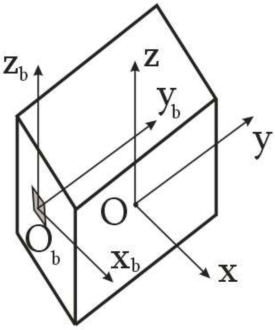
Therefore, let us consider a special case. Let the origin of the magnetometer's structural coordinate system be located on one of the axes of the main body axis system. And the Obxbybzb axes of the structural coordinate system and Oxyz axes of the main body axis systems are parallel (Figure 4).
In this case, taking into account the introduced simplifying assumption, equations (3) are transformed to the form [24]:
{ I x x ω ˙ x k + ω y k ω z k ( I z z I y y ) = M x I y y ω ˙ y k + ω x k ω z k ( I x x I z z ) = M y I z z ω ˙ z k + ω x k ω y k ( I y y I x x ) = M z .
Let us rewrite equations (4) with respect to the diagonal inertia moments in the structural coordinate system:
{ ω ˙ x k I x x I y y ω y k ω z k + ω y k ω z k I z z = M x ω ˙ y k I y y + ω x k ω z k I x x ω x k ω z k I z z = M y ω ˙ z k I z z ω x k ω y k I x x + ω x k ω y k I y y = M z .
Let us assume that the quantity of the controlled action is significant enough to neglect the external disturbing action. Then the right parts of equation (5) will represent the moment from the controlled action in the magnetometer's structural coordinate system (Figure 4):
M = r × F c o n t ,
where r is the radius-vector of the application point of the controlled action relative to the origin of the magnetometer's structural coordinate system; F c o n t is the vector of the controlled action.
Let us express the diagonal components of the inertia tensor from system (5):
{ I z z = M z ω ˙ x k + M x ω x k ω y k ( M y ω ˙ x k M x ω x k ω z k ) ω x k ω y k 2 ω z k ω x k ω y k ω ˙ x k ω ˙ x k ω ˙ y k + ω x k ω y k ω z k 2 ω ˙ x k ω ˙ z k + ω x k ω y k 2 ω z k + ( ω x k ω y k 2 ω z k ω x k ω y k ω ˙ x k ) ω x k ω z k ω ˙ x k ω x k ω y k ω z k 2 ω ˙ x k ω ˙ y k + ω x k ω y k ω z k 2 ; I y y = I z z ω x k ω z k ω ˙ x k + ω x k ω y k ω z k 2 ω ˙ x k ω ˙ y k + ω x k ω y k ω z k 2 + M y ω ˙ x k M x ω x k ω z k ω ˙ x k ω ˙ y k + ω x k ω y k ω z k 2 ; I x x = M x + ω y k ω z k I y y ω y k ω z k I z z ω ˙ x k .
Upon transition to the main body axis system of the space debris object, let us transform the inertia tensor in accordance with the Huygens-Steiner theorem. In the considered case, the axes of the main body axis system of the space debris object and the magnetometer's structural coordinate system are parallel (Figure 6). The y and yb axes are offset from each other (Figure 6). Therefore we have:
I ^ = [ I x x                0                       0 0            I y y + m a 2             0 0                   0                I z z + m a 2 ] ,
where m is the mass of the space debris object; a is the distance between the y and yb axes of the main body axis system of the space debris object and the magnetometer's structural coordinate system (Figure 4).
In this particular case, the components of the inertia tensor are relatively easy to find. Let us illustrate it with an example in the next section of the paper.

3. Numerical simulation for the Aist-2D small spacecraft.

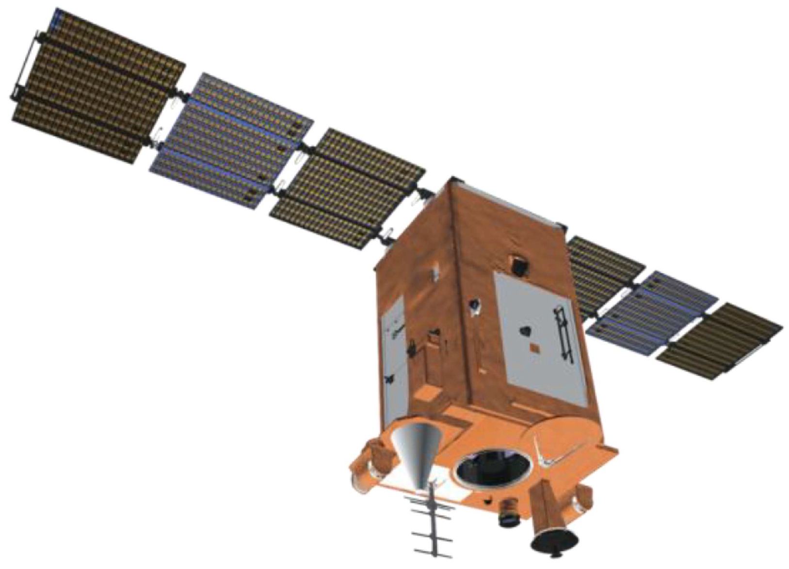
Let us consider an example for estimating the inertial-mass parameters of the Aist-2D small spacecraft for remote sensing of the Earth (Figure 7 [25]).
The main parameters of the Aist-2D small spacecraft for remote sensing of the Earth are presented in Table 1 [26].
The main parameters of the simulated «Aist-2D» spacecraft [26]
Modern measuring instruments provide high accuracy in measuring the components of the Earth's magnetic field induction vector [27]. Therefore, their application can provide an effective estimation of the inertial-mass parameters for the space debris object. Thus, proton precession magnetometers and optically pumped magnetometers have a sensitivity of about 10–50 pT, an absolute accuracy of about 0.1–1.0 nT, and a dynamic range of 1–100 μT [28].
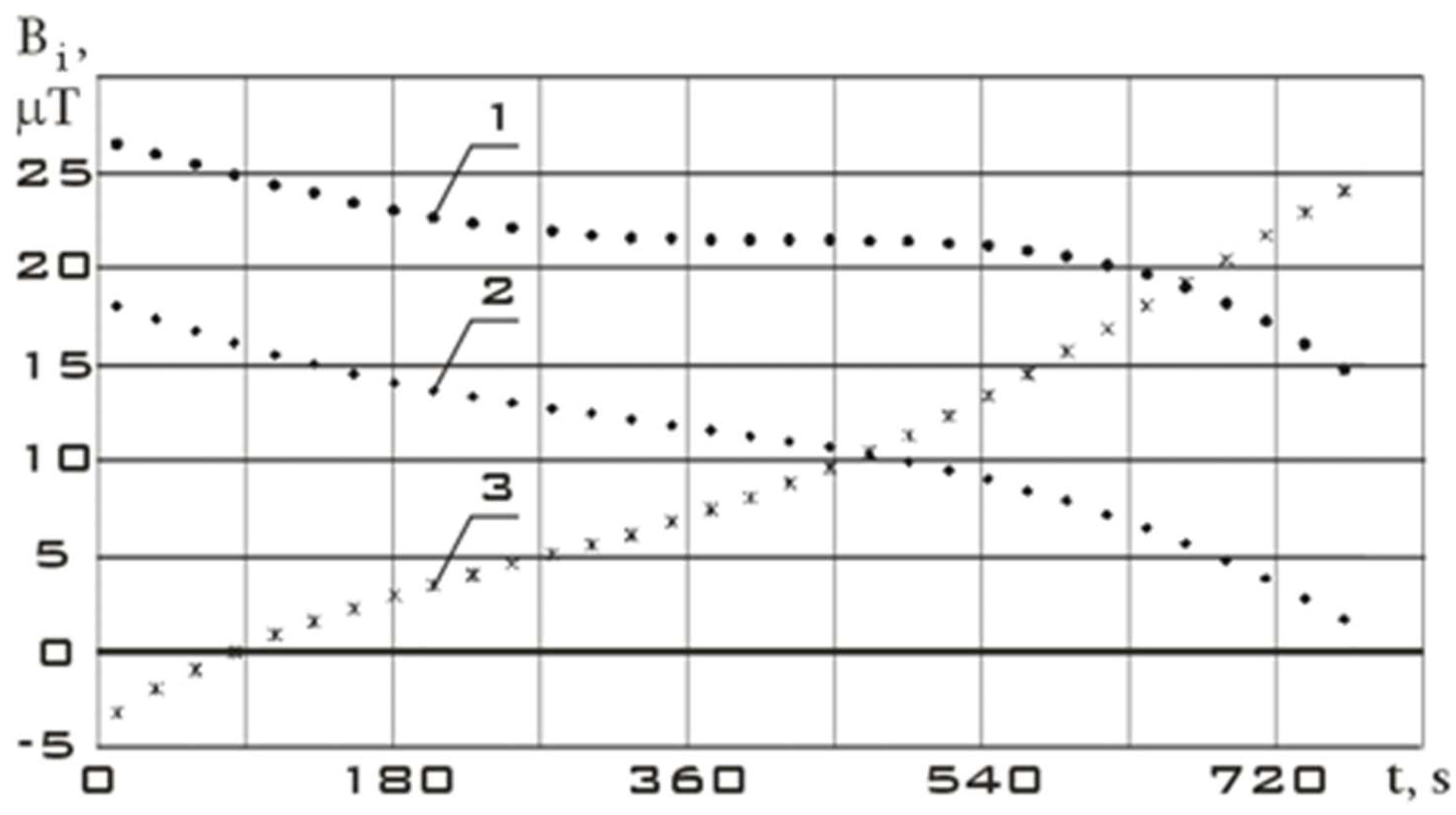
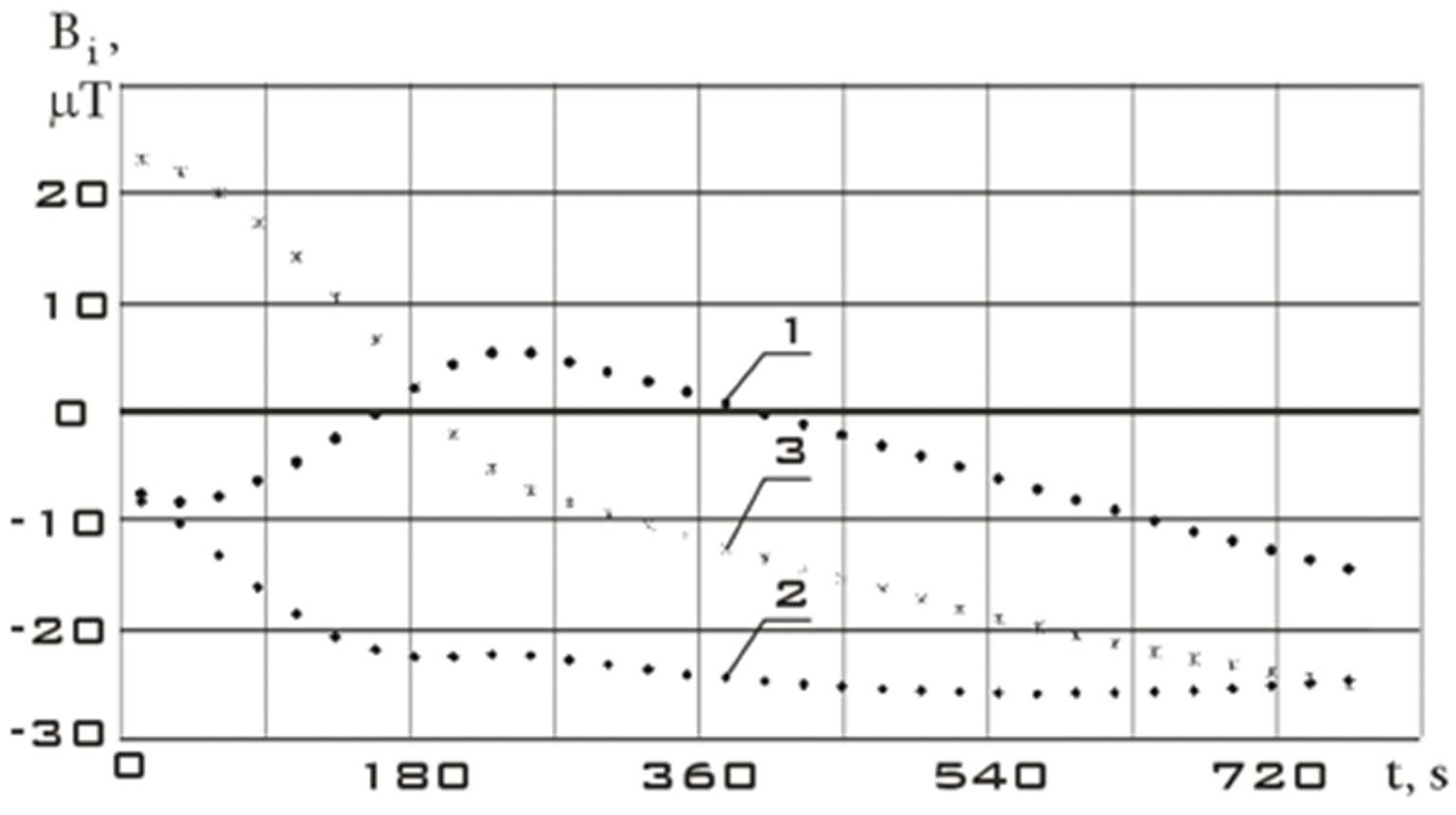
As the initial section before the controlled action, let us consider the stabilization section of the Aist-2D small spacecraft. The measurement data for this section are shown in Figure 6. Time t = 0 corresponds to 07/31/2016 14:35:46 Moscow time.
Let us choose the section of reorientation of the Aist-2D small spacecraft as a section with controlled action. The measurement data for this section are shown in Figure 7. Time t = 0 corresponds to 07/31/2016 19:34:28 Moscow time.
To correctly estimate the derivative of the Earth's magnetic field induction vector components, it is necessary to have continuous dependences of these components on time. These dependencies are then used in formulas (1) and (2) to determine the vector of angular velocity and rotational acceleration of the space debris object in the magnetometer's structural coordinate system.
Let us restore discrete measurements to continuous dependencies using the Kotelnikov series [29], since there are measurement data at regular intervals:
B j ( t ) = k = B j k sin [ π Δ t ( t k Δ t ) ] π Δ t ( t k Δ t ) ,
where j = x, y, z; Bjk are the measurements at the time tk; Δ t = Δ t k is the uniform step between measurements.
Continuous dependencies corresponding to Figure 6 and Figure 7 and obtained using the Kotelnikov series (9) are shown in Figure 8. The derivatives of these functions are shown in Figure 9.
The variation ranges of the Earth's magnetic field induction vector components in the reorientation mode are much wider than in the stabilization mode (Figure 8). It should be noted that the variation ranges of derivatives in different modes are comparable. However, the analysis of Figure 9 shows that in the stabilization mode, the derivatives fluctuate around zero with a sign change. In the reorientation mode, the derivatives have the same sign for a long period of time. This can be explained by the fact that in the stabilization mode there are random fluctuations in the orientation angles with a change in the sign of the angular velocity. In the reorientation mode, the angular position of the small spacecraft purposefully changes. This is achieved by the fact that the angular velocity has the same sign for a significant period of time. Thus, we can talk about the correct restoration for the continuous dependences of the Earth's magnetic field induction vector components using the Kotelnikov series (9).
Let us further estimate the angular velocity by formula (2). The estimation results are shown in Figure 10.
The derivative of the angular velocity - angular acceleration - will have the form shown in Figure 11.
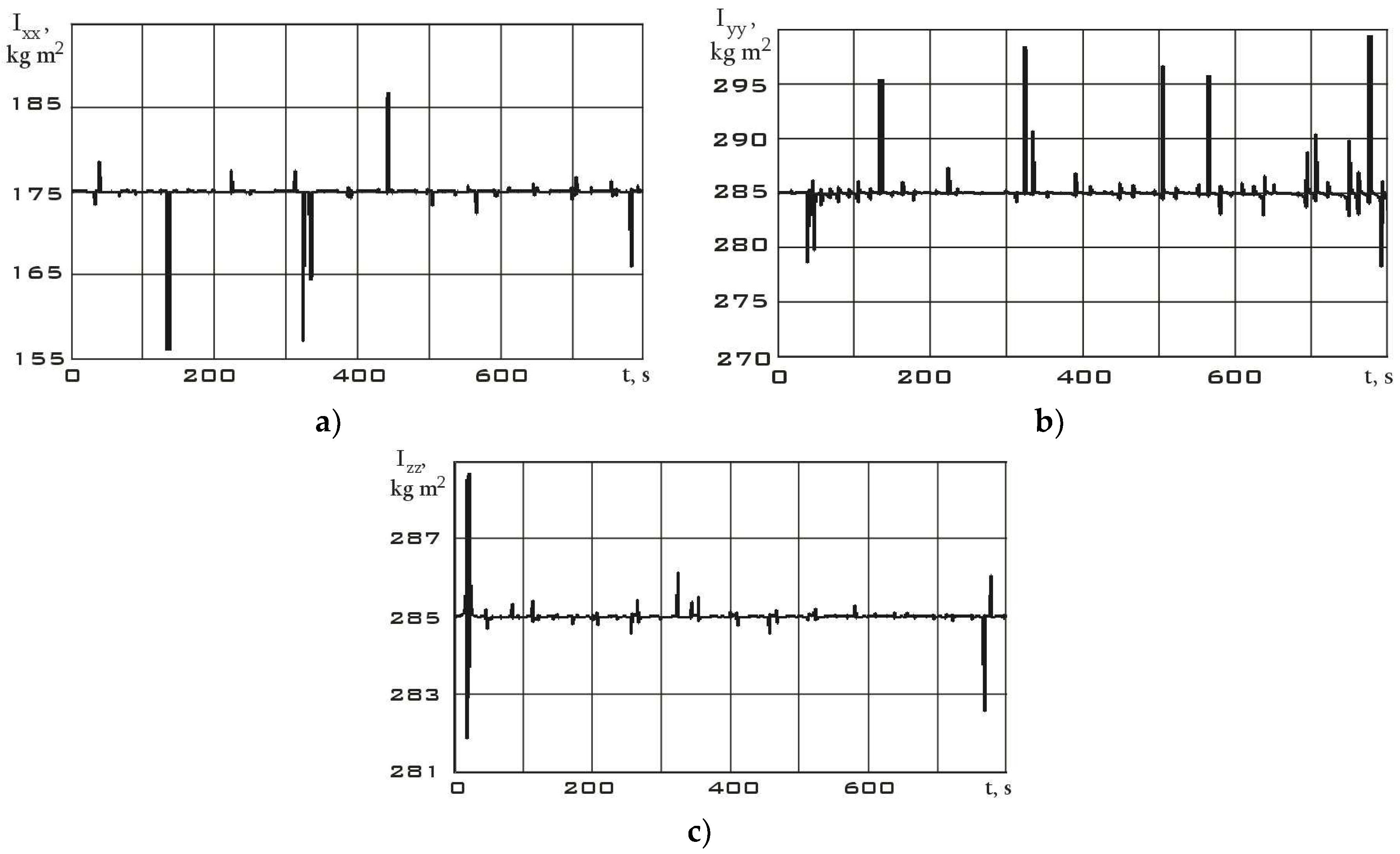
The values of the angular velocity and angular acceleration in the stabilization mode are significantly lower than in the reorientation mode (Figure 10). This fact is an important difference between different modes. Using system (7), let us estimate the dependences for the diagonal components of the Aist-2D small spacecraft inertia tensor according to the measurement data. These dependencies are shown in Figure 12 for the stabilization mode and in Figure 13 for the reorientation mode.
Bursts on the graphs of the diagonal components of the inertia tensor are associated with both measurement errors and approximation errors of these measurements by the Kotelnikov series (9). Small oscillations in the dependences can be explained by the errors in the attachment of measuring equipment relative to the main body axis system, as well as natural oscillations of the solar panels of the Aist-2D small spacecraft. These oscillations influenced the components of the inertia tensor and gave them a dynamic component. In general, analyzing Figure 12 and Figure 13, we can state a fine results precision with data from Table 1. It can also be seen that in the reorientation mode the diagonal components of the inertia tensor are determined more reliably. This is due to the fact that the moment from the executive bodies of the Aist-2D small spacecraft (flywheel engines) was determined more accurately than the moment from many disturbing factors in the stabilization mode.
4. Conclusion

Thus, as a result of the investigations carried out in the paper, a theoretical estimation of the diagonal components of the space debris object inertia tensor was obtained in the simple case of attaching the measuring equipment on this object. It was assumed that the structural axes of the measuring equipment coincide with the main body axes of the space debris object. As an example, the Aist-2D small spacecraft for remote sensing of the Earth was taken. On its example, the possibility of estimating the diagonal components of the inertia tensor using the measurement data of the Earth's magnetic field induction vector is demonstrated. The average values of the disturbing factors (in the stabilization mode) and the moments of flywheel engines (in the reorientation mode) were chosen as the controlled action on the small spacecraft. The results showing a fine precision with the diagonal components of the inertia tensor of the Aist-2D small spacecraft are obtained. The results of the work can be used in estimating the inertial-mass parameters of space debris objects during the implementation of missions to clean up near-Earth space.

Acknowledgments

This study was supported by the Russian Science Foundation (Project No. 22-19-00160).

References

  1. Kessler, D.J.; Burton, G. C.-P. Collision Frequency of Artificial Satellites: The Creation of a Debris Belt. Journal of Geophysical Research 1978, 83, A6, 2637–2646. [CrossRef]
  2. Orbital Debris: A Chronology, NASA/TP-1999-208856, January 1999, http://ston.jsc.nasa.gov/collections/TRS/_techrep/TP-1999-208856.pdf.
  3. Schaub, H.; Sternovsky, Z. Active space debris charging for contactless electrostatic disposal maneuvers. Advances in Space Research 2014, 53, 1, 110–118. [CrossRef]
  4. Rossi, A. The earth orbiting space debris. Serbian Astronomical Journal 2005, 170, 1–12. [CrossRef]
  5. Satellite Applications Catapult, “Small Satellite Market Intelligence Report Q3 2021,” 2021.
  6. Krestina, A.V.; Tkachenko, I.S. Efficiency Assessment of the Deorbiting Systems for Small Satellite. Journal of Aeronautics, Astronautics and Aviation 2022, 54, 2, 227–240.
  7. Burkhardt, H.; Sippel, M.; Krülle, G.; Janovsky, R.; Kassebom, M.; Lübberstedt, H.; Romberg, O.; Fritsche B. Evaluation of Propulsion Systems for Satellite End-Of-Life De.Orbiting In Proceedings of the 38th AIAA/ASME/SAE/ASEE Joint Propulsion Conference & Exhibit 07 July 2002 - 10 July 2002, Indianapolis, Indiana, USA.
  8. Serfonteina, Z.; Kingston, J.; Hobbs, S.; Holbrough, I.E.; Beck, J.C. Drag Augmentation Systems for Space Debris Mitigation. Acta Astronautica 2021, 118, 278–288. [CrossRef]
  9. Serfonteina, Z.; Rigamonti, Lt. M.; Demers, E.; Temprano, G.; Kingston, J. LEOniDAS Drag Sail Experiment on the 2021 ESA Fly Your Thesis! Parabolic Flight Campaign. In Proceedings of the 4th Symposium on Space Educational Activities Barcelona, April 2022.
  10. Sanchez-Arriaga,G.; Sanmartin, J.R.; Lorenzini, E.C. Comparison of Technologies for Deorbiting Spacecraft From Low-Earth-Orbit at End of Mission. Acta Astronautica 2017, 138, A7, 536–542. [CrossRef]
  11. Sedelnikov, A.V.; Bratkova, M.E.; Khnyryova E.S. Algorithm for the Operation of the Data-measuring System for Evaluating the Inertial-mass Characteristics of Space Debris. Lecture Notes in Electrical Engineering 2023, 1047.
  12. Aslanov, V.S.; Ledkov, A.S. Dynamics of reusable tether system with sliding bead capsule for deorbiting small payloads. Journal of Spacecraft and Rockets 2018, 55, 6, 1519–1527. [CrossRef]
  13. Trushlyakov, V.I.; Yudintsev, V.V. Rotary space tether system for active debris removal. Journal of Guidance, Control, and Dynamics 2020, 43, 2, 354–364. [CrossRef]
  14. Wang, Q.; Jin, D.; Rui X. Dynamic Simulation of Space Debris Cloud Capture Using the Tethered Net. Space: Science & Technology 2021, doi.org/10.34133/2021/9810375. [CrossRef]
  15. Botta, E.M.; Sharf, I.; Misra A.K. Contact Dynamics Modeling and Simulation of Tether-Nets for Space Debris Capture. Journal of Guidance, Control, and Dynamics 2017, 40, 1, 110–123. [CrossRef]
  16. Shen, S.; Xing, J.; Hao C. Cleaning space debris with a space-based laser system. Chinese Journal of Aeronautics 2014, 27, 4, 805–811.
  17. Ledkov, A.S.; Aslanov, V.S. Review of contact and contactless active space debris removal approaches. Progress in Aerospace Sciences 2022, 134, 100858. [CrossRef]
  18. Bombardelli, C.; Pelaez, J. Ion Beam Shepherd for Contactless Space Debris Removal. Journal of Guidance, Control, and Dynamics 2011, 34, 3, 916–919. [CrossRef]
  19. Ledkov, A.S.; Aslanov, V.S. Active space debris removal by ion multi-beam shepherd spacecraft. Acta Astronautica 2023, 205, 247–257. [CrossRef]
  20. Bourabah, D.; Field, L.; Botta, E. Estimation of uncooperative space debris inertial parameters after tether capture. Acta Astronautica 2023, 202, 11, 909–926. [CrossRef]
  21. Chu, Z.; Ma, Y.; Hou, Y.; Wang, F. Inertial parameter identification using contact force information for an unknown object captured by a space manipulator. Acta Astronautica 2016, 131, 69–82. [CrossRef]
  22. Lomaka, I.A. A possible approach to the identification of inertial parameters of large-sized space debris using a specialized nanosatellite. Journal of Physics: Conference Series 2020, 1536, 012002. [CrossRef]
  23. Carletta, S.; Teofilatto, P. Design and Numerical Validation of an Algorithm for the Detumbling and Angular Rate Determination of a CubeSat Using Only Three-Axis Magnetometer Data. International Journal of Aerospace Engineering 2018, 3, 9768475. doi: 10.1155/2018/9768475. [CrossRef]
  24. Ovchinnikov M.Yu., Penkov V.I., Roldugin D.S., Ivanov D.S. Magnetic navigation systems of small satellites. 2016, Moskow: Applied Mathematics Institute of M.V. Keldysh of the Russian Academy of Sciences, p. 366.
  25. Sedelnikov, A.V.; Orlov, D.I.; Serdakova, V.V.; Nikolaeva, A.S. The Symmetric Formulation of the Temperature Shock Problem for a Small Spacecraft with Two Elastic Elements. Symmetry 2023, 15, 1, 172; doi:10.3390/sym15010172. [CrossRef]
  26. Filippov, A.S. Development of an effective method for ground-based testing of magnetometer sensors scientific equipment of the «MAGKOM» on small space vehicles such as «AIST». Aerospace Instrumentation 2017, 3, 37–47.
  27. Bennett, J.S.; Vyhnalek, B.E.; Greenall, H.; Bridge, E.M.; Gotardo, F.; Forstner, S.; Harris, G.I.; Miranda, F.A.; Bowen, W.P. Precision Magnetometers for Aerospace Applications: A Review. Sensors 2021, 21, 5568. [CrossRef]
  28. Korth, H.; Strohbehn, K.; Tejada, F.; Andreou, A.G.; Kitching, J.; Knappe, S.; Lehtonen, S.J.; London, S.M.; Kafel, M. Miniature atomic scalar magnetometer for space based on the rubidium isotope 87Rb. JGR Space Phys. 2016, 121, 7870–7880. [CrossRef]
  29. Sedelnikov A.V. Fast Analysis of Onboard Measurements of the Earth Magnetic Field for the Purpose of Microaccelerations Decrement on Board of the “AIST” Small Spacecraft During its Uncontrolled Orbital Flight. International Review of Aerospace Engineering 2018, 11, 2, 76–83. [CrossRef]
Figure 1. A method for removing space debris using a space tug and a tether system.
Preprints 89715 g001
Figure 2. Deceleration of space debris using the ion beam [18].
Preprints 89715 g002
Figure 3. Scheme of attaching the magnetometer on the space debris object in an arbitrary case: Oxyz is the main body axis system of the space debris object; Obxbybzb is the structural coordinate system of the magnetometer.
Preprints 89715 g003
Figure 4. Scheme of attaching the magnetometer on the space debris object in the special case.
Preprints 89715 g004
Figure 5. Appearance of the Aist-2D small spacecraft for remote sensing of the Earth [25].
Preprints 89715 g005
Figure 6. Components of the Earth's magnetic field induction vector in the magnetometer's structural coordinate system in stabilization mode: 1 is Bx; 2 is By; 3 is Bz.
Preprints 89715 g006
Figure 7. Components of the Earth's magnetic field induction vector in the magnetometer's structural coordinate system in reorientation mode: 1 is Bx; 2 is By; 3 is Bz.
Preprints 89715 g007
Figure 8. Continuous dependencies of the Earth's magnetic field induction vector components in the magnetometer's structural coordinate system, restored using the Kotelnikov series (9): а) in stabilization mode (Figure 6); b) in reorientation mode (Figure 7) 1 is Bx; 2 is By; 3 is Bz.
Preprints 89715 g008
Figure 9. Derivatives of continuous dependencies of the Earth's magnetic field induction vector components in the magnetometer's structural coordinate system (Figure 8): а) in stabilization mode; b) in reorientation mode dBx/dt (black); dBy/dt (blue); dBz/dt (red).
Preprints 89715 g009
Figure 10. Dependences for the components of the angular velocity vector in the magnetometer's structural coordinate system, estimated by formula (2): а) in stabilization mode; b) in reorientation mode ωx (black); ωy (blue); ωz (red).
Preprints 89715 g010
Figure 11. Dependences for the components of the angular acceleration vector in the magnetometer's structural coordinate system: а) in stabilization mode; b) in reorientation mode εx (black); εy (blue); εz (red).
Preprints 89715 g011
Figure 12. Dependences for the diagonal components of the inertia tensor in the magnetometer's structural coordinate system in stabilization mode: а) Ixx; b) Iyy; c) Izz.
Preprints 89715 g012
Figure 13. Dependences for the diagonal components of the inertia tensor in the magnetometer's structural coordinate system in reorientation mode: а) Ixx; b) Iyy; c) Izz.
Preprints 89715 g013
Table 1.
Table 1.
Parameter Designation Value Dimension
Mass m 530 kg
Axial moments of inertia Ixx
Iyy
Izz
175
200
285

kg· m2
Maximum control torque M 0.2 N·m
Disclaimer/Publisher’s Note: The statements, opinions and data contained in all publications are solely those of the individual author(s) and contributor(s) and not of MDPI and/or the editor(s). MDPI and/or the editor(s) disclaim responsibility for any injury to people or property resulting from any ideas, methods, instructions or products referred to in the content.
Copyright: This open access article is published under a Creative Commons CC BY 4.0 license, which permit the free download, distribution, and reuse, provided that the author and preprint are cited in any reuse.
Prerpints.org logo

Preprints.org is a free preprint server supported by MDPI in Basel, Switzerland.

Subscribe

© 2024 MDPI (Basel, Switzerland) unless otherwise stated