Preprint
Article

Influence of Aspect Ratio of Nylon Fibers on the Mechanical Properties of Concrete

Altmetrics

Downloads

168

Views

2464

Comments

1

This version is not peer-reviewed

Submitted:

27 November 2023

Posted:

29 November 2023

You are already at the latest version

Alerts
Abstract
The initiation of micro-cracks in concrete is primarily due to its brittleness, which causes severe impacts on the overall behavior of the concrete. However, incorporating fibers in concrete could significantly improve its mechanical properties. The current study demonstrates the influence of two types of fibers on the mechanical properties of concrete. Nylon Fiber Threads (NFT) and Nylon Fiber Strands (NFS) at a fiber content of 2.5 kg/m3 were incorporated in the concrete mix. Concrete with a compressive strength of 30 MPa and a water-cement ratio of 0.4 was produced to investigate the fresh and mechanical properties of conventional and nylon-fiber reinforced concrete (NFRC). The concrete prims and cylinders were tested for compressive, splitting, and flexural strength using ASTM standards (ASTM C-39, C-496, and D-790, respectively). It was found that NFT-reinforced samples achieved higher mechanical properties of concrete (13.05%) compared to NFS-reinforced samples. Test results showed that incorporation of nylon fibers (NF) in concrete decreased the compressive strength of cylindrical and cubical specimens by 0–10% and 5–15%, respectively. However, it increased the splitting tensile and flexural strengths by 0-15%, and 5-15% respectively. Furthermore, the incorporation of NF in concrete significantly improved the ductility and delayed the crack initiation in concrete.
Keywords: 
Subject: Engineering  -   Civil Engineering

1. Introduction

The construction industry is one of the most rapidly growing industries across the globe. In this industry, concrete is a commonly used construction material and is acceptable for many applications in construction industries [1,2]. Fresh concrete can be shaped and molded as needed, which offers a suitable replacement for other construction materials such as brick and stone masonry. The strength of concrete can be suitably changed by changing the composition and mix design ratio of its components [3]. Concrete will continue to be widely used worldwide due to its good compressive strength, high plasticity, and flowability when in a fresh condition, durability and fire resistance when hardened, and even relatively low cost [4,5]. Research on the mechanical properties of newly developed concrete construction materials is necessary for characterizing their performance for field execution [6,7,8].
The performance of concrete is governed by its compressive, splitting tensile, and flexural strength. Its tensile strength is comparatively lower than the compressive strength due to the early crack propagation. The compressive strength, in turn, is influenced by progressive cracking phenomena that have an impact on the meso- and macro-scale behavior of concrete [9], requiring particular attention in the identification procedure starting from experimental data [10]. Aggregates with fibers attain high compressive strength of concrete and increase the impact strength of concrete by binding all the constituents of the concrete together. Meanwhile, concrete has undesirable properties like brittleness, weak tension, low resistance cracking, and an instant breakdown under certain weights [11]. On the other hand, these drawbacks can be addressed by adding various fibers to the concrete mix. The incorporation of concrete with fibers is called fiber-reinforced concrete (FRC)[12]. FRC is a composite material of cement, sand, aggregates (fine and coarse), water, and fibers [13]. The short discrete fibers are randomly arranged throughout the total mass of concrete in the composite material [14]. Using discontinuous concrete fibers to increase concrete's tensile strain capacity is one approach to prevent crack formation in concrete [15].
The inclusion of fibers in concrete during its fresh state has the potential to mitigate the occurrence of plastic shrinkage fractures. In addition, it plays a role in the occurrence of fiber bridging and intermeshing, which effectively reduces the formation of micro-cracks in the first phases and impedes the formation of macro-cracks [16]. Microfiber acts as a bridge to prevent the production of macro cracks, increasing the splitting strength of concrete. Microfibers may be removed after macro cracks appear because of their shorter length [17]. Moreover, properties of FRC have increased in the construction industry because the reinforced fibers in concrete may enhance concrete's toughness, tensile strength, flexural strength, impact strength, and failure mode [18]. In addition, it is well recognized that incorporating fibers into concrete has little or no effect on compressive strength and elastic modulus [19]. Adding fiber to concrete has better deformation capacity than plain cement concrete (PCC) [20]. It is necessary to understand the mechanical characteristics of FRC in the hardened condition to construct the structure based on its intended usage [21]. The stress-stain relationship of concrete is crucial for the axial arrangement of short columns and the flexural design of beams and slabs [22]. A complete stress-strain curve of concrete is essential to analyze the mechanical performance of FRC structures [23]. Therefore, NF is one of the possible solutions to characterize the fresh and mechanical properties of FRC. The nylon fiber is strong and has better elastic behavior when used in concrete [24]. Apart from concrete, the flexural strength and resistance to cracks initiation of cement mortar could be improved by adding nylon fiber. As reported in the literature, nylon fibers have better elastic recovery, good tenacity, and toughness [25,26]. According to Song et al.[27], the nylon fiber concrete's improved the modulus of rupture (MOR) and compression and split tensile strengths i by 6.3%, 6.7%, and 4.3%, respectively, than the polypropylene fiber concrete at a fiber content of 0.6 kg/m3. Najafi et.al [28] investigated the hardened properties of NFRC by casting beams, cylinders, and cubes. The authors found a 5-15% improvement in compressive, splitting, and flexural strength of NFRC samples compared with the control sample with 0% fiber. In addition, as compared to the other fibers, NF is the cheapest and most easily available fibers in the construction industry. Furthermore, nylon offers the potential for a greater range of applications because to its higher melting point than other flexible polymers like polypropylene (PP), polyethylene (PE), and polyethylene terephthalate (PET)[28].
The detailed literature review showed that nylon fibers are an appropriate option for increasing the ductility of PCC composites and improving the mechanical properties. Furthermore, the incorporation of NF also improves the flexibility of PCC composites. Hence, this research investigates the critical performance of NF-reinforced concrete. The authors believe that the test results of this research study would extend the potential use of widely available nylon fibers in PCC for durable concrete structural members. The test results were conscientiously analyzed. Nowadays, the demand for the safety of heavily loaded structures against severe loading conditions like earthquake loads and other accidental loads is increasing. Consequently, high-performance manufacturing materials with better flexural and shear properties are required to fulfill the intended function of novel and modified concrete. However, the existing research focused on the typical length and types of NF and didn’t explore their effect in terms of aspect ratio and overall stress-strain behavior. Therefore, to achieve the selected properties, fibers with different sizes and shapes were used. The new types of fibers were investigated as micro reinforcements, and the mechanical characteristics of fibers were demonstrated using stress-strain relationships. The current study investigated the axial compressive, splitting tensile, and flexural behavior of normal strength NFRC. The nylon fibers used in this study were of two types: NFT and NFS. The primary factors considered in this study were W/C ratio, admixture, and fiber contents.

2. Experimental Program

2.1. Materials

An ordinary Portland cement (OPC) provided by type-1 (Pioneer Cement Ltd) following the American Standard of Testing Materials (ASTM C-150) was used in the mix proportioning and casting of NFRC. Cement is a binder material used in concrete. The density and specific gravity of cement are 1440 kg/m3 and 3.15. This type of cement provides better performance and high strength to concrete structures. The chemical compositions of OPC as shown in Table 1.
Uniformly graded coarse aggregate (size 12.5 mm [1/2 in.]) was used in this study. The density and specific gravity of the Sargodha crush are 1660 kg/m3 and 2.72. Fine aggregate (standard size less than 2.36 mm) was used. The density and specific gravity of the sand are 1550 kg/m3 and 2.69. The gradation of coarse and fine aggregate was performed as per (ASTM C-136). Table 2 shows the total quantities of cement, sand, aggregates, and water. The high-range water reducer admixture Rheobuild-800 used in this research was supplied by New Master Builders. Figure 1 shows the two types of fibers (NFT and NFS) used to investigate their effect on the mechanical properties of developed concrete. The individual NFT was 0.14 mm [0.005 in.] in diameter and 25 mm [1 in.] in length. The NFS was prepared in the laboratory using a single layer of epoxy on fifty threads of Nylon Fibers. The individual NFS was 2 mm [0.08 in.] in diameter and 25 mm [1 in.] in length. NF was supplied by (Nylon Fabric). The properties of NF as shown in .

2.2. Mix Proportions

For this research, concrete with a desired compressive strength of 30 MPa was produced to investigate the fresh and mechanical properties of NFRC mixes. The design mix proportion ratio of 1:1.4:1.6 with a water-cement ratio (W/C) of 0.4 was used to prepare the concrete specimens. There were three mixed proportions, including the conventional concrete for the cylinders, cubes, and prisms. Table 4 shows the mix proportion ratio of the cylinder for compressive and tensile strength. Table 5 shows the mix proportions of Plain, NFT, and NFS mixes of the cube for compression behavior. Table 6 shows the mix proportions of Plain, NFT, and NFS mixes of the prism for flexural behavior. In mix proportion, the mix with 0% fiber was considered as the reference mix. The mix proportions were designed by adding nylon fiber to the total mass of the coarse aggregates (2.5 kg/m3) and a low amount of Superplasticizer (10 mL per 1 kg cement). A total of 9 mixes were developed 3 for each (cube, cylinder, and prim) to assess the mechanical properties and stress-stain behavior of NFRC.

2.3. Mixing Procedure

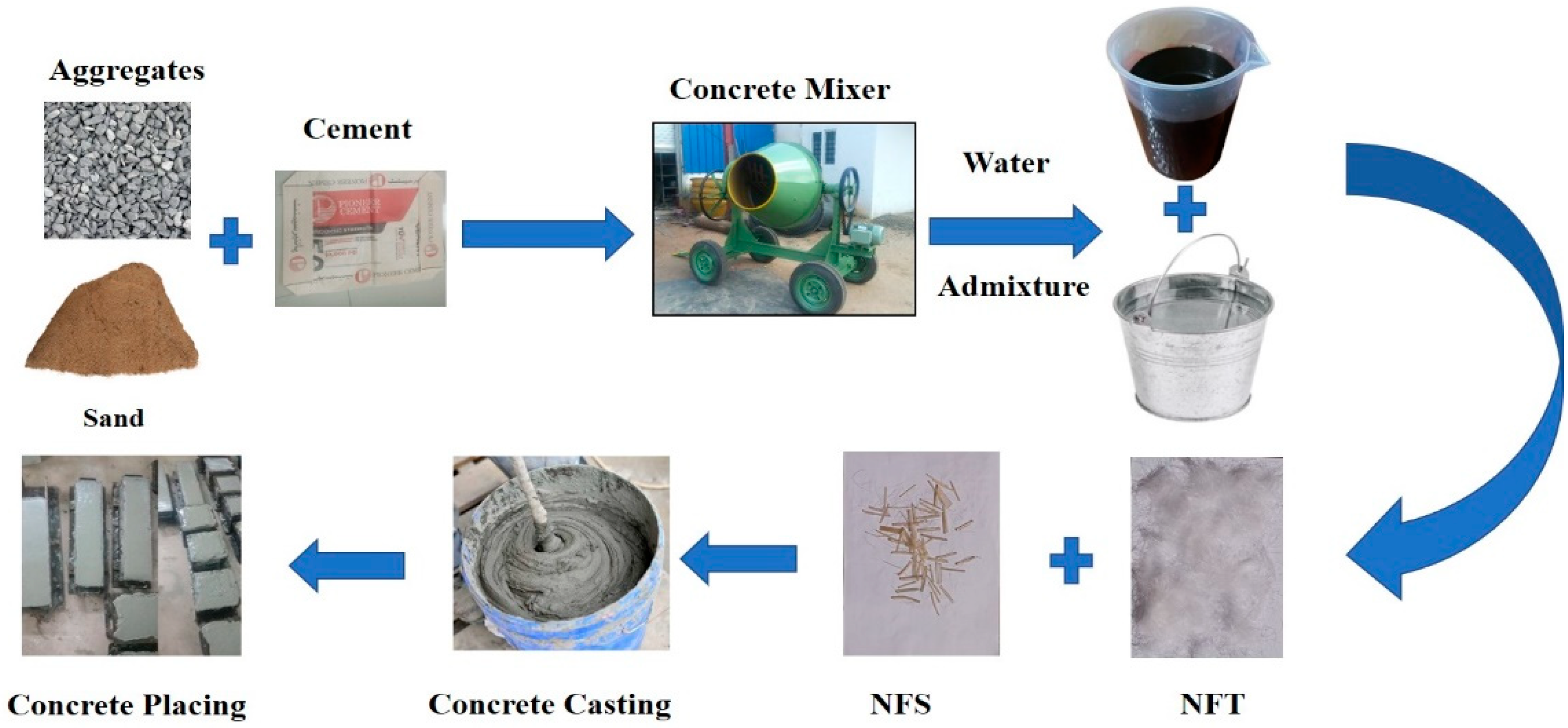
Mixing procedures of NFRC mixes included the following outline. Initially, the coarse aggregates were washed to remove the dust and placed in a dry clean area to achieve Surface-saturated dry (SSD) condition. Then they were placed in a concrete mixer with fine aggregates. The aggregate and sand were mixed for 2 minutes, and add cement mixed for 1 minute. A specified amount of nylon fibers was added to the mixer and continued mixing for 1.5 minutes. Next, the water to the concrete mixer for 30 seconds was added, and then the Superplasticizer was mixed with the remaining water for 2 minutes. The mixer stopped after 7 minutes. This mixing technique was effective in achieving the desired workability. The fresh mixes of PCC and NFRC were poured into the cylinders and cube molds for the compressive and splitting tensile strengths. Prism molds were filled and cast to investigate the flexural behavior of NFRC. The dimensions of cylinders, cubes, and beams molds were 150 x 300 mm2, 150 x 150 x 150 mm3, and 500 x 100 x 100 mm3 as depicted in Figure 2.

2.4. Preparation of Specimens

Cylindrical steel molds of compressive strength (CS) of size (150 mm diameter and 300 mm length) as per (ASTM C39) were used to cast the specimens. The specimens for splitting strength were also cast in cylindrical steel molds of the same size (150 mm diameter and 300 mm length) as per (ASTM C496). All cylindrical molds were capped with high-strength plaster before testing. The specimens for the flexural strength test were cast in plywood prism molds of cross-section and length (100 x 100 x 500 mm). The prism molds were prepared at the laboratory as per the specifications of the beam for flexural strength using ASTM (D790). The vibrating table was employed to compact the cast specimens and was found effective in eliminating the air voids entrapped from the specimens during casting. The upper surface of the specimens was finished using a trowel. After that, specimens were left in the laboratory for one day under ambient curing conditions (temperature of 33 ± 2°C). The day after the casting, the samples were demolded, and the specimens were submerged in the water tank till the testing day for the determination of the mechanical properties of concrete according to ASTM standards.

2.5. Methods for Testing

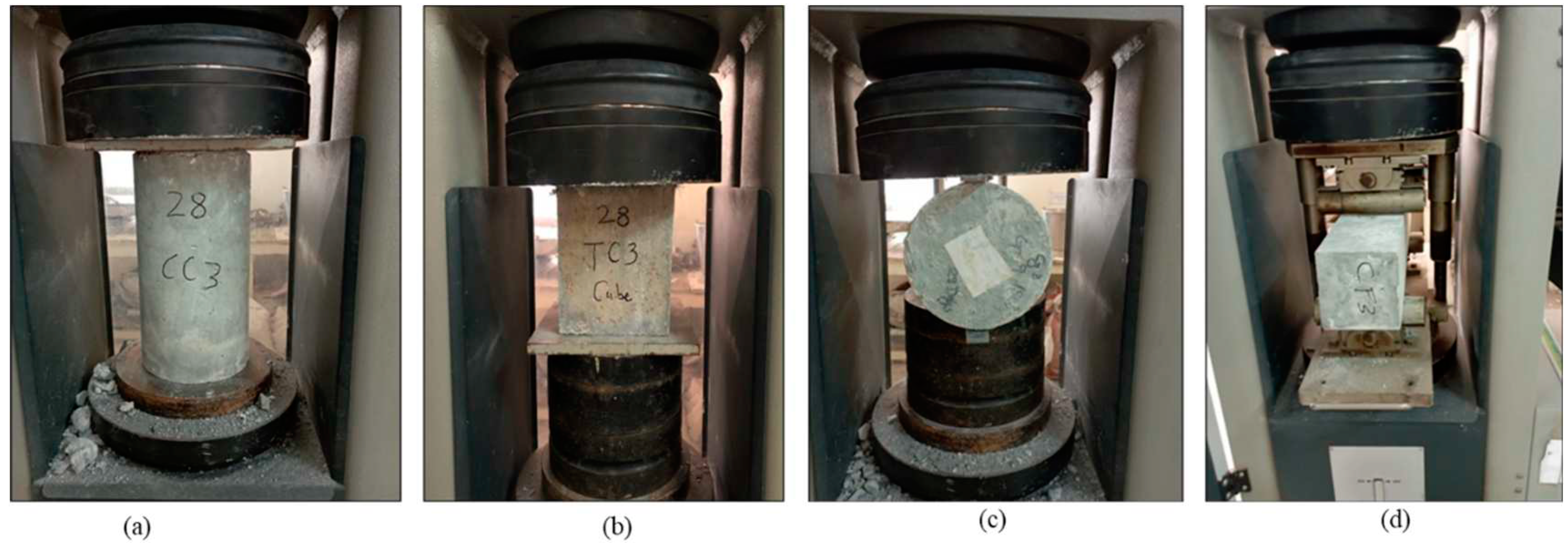
Slump cone tests were conducted to find out and compare the workability of PCC with NFRC. The slump tests were performed to determine the workability of plain and fibrous concrete mixes under (ASTM C143). The density of PCC and NFRC specimens was determined under (ASTM C29) at 28 days. The compressive strength of standard specimens at 7 and 28 days as shown in Figure 3 was tested through a compression testing machine (CTM) according to (ASTM C39) with a loading rate under 0.250 MPa/s for a cylindrical specimen and 0.600 MPa/s for a cubical specimen with a total capacity of 1500 kN. To investigate the splitting tensile (ASTM C496) and flexural (ASTM D790) strengths at 28 days of the developed concrete, a loading rate of 0.02mm/s and 0.250 MPa/s for cylinders and prisms respectively, with a total machine capacity of 1,000 kN. was applied as showed in Figure 3(c, d). The comparison between the different mechanical properties of the tested concrete specimens was made through the stress-strain curve calculated from the test results.

3. Experimental Results and Discussion

3.1. Workability

The workability of fresh NFRC was determined using the slump cone and compacting factor test. Adding NFS and NFT decreased the workability of fresh concrete. However, a superplasticizer was used to achieve the desired workability of fresh concrete. The slump cone test was organized for fresh concrete. Table 7 shows the slump test values in the 3rd column for PCC, NFT, and NFS. It was noticed that the addition of fibers in concrete can diminish the workability of concrete using the W/C ratio of 0.4.

3.2. Density

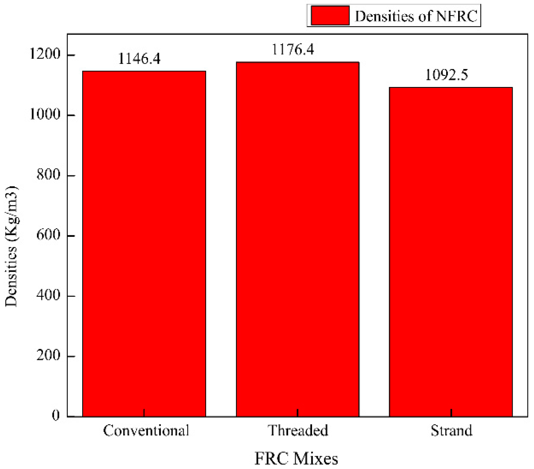
Densities of concrete specimens of PCC and NFRC as per (ASTM C29) at 28 days. Table 7 shows the density test results in the 4th column for PCC, NFT, and NFS. Adding fibers (only NFT) in concrete increased the densities of NFRC when compared to PCC. The increased density of NFT showed better mixing and compaction of NFRC specimens. The densities of PCC, NFT, and NFS were 1146.4 kg/m3, 1176.4 kg/m3, and 1092.5 kg/m3 respectively. An increase of 30 kg/m3 was noted in the density of NFT. The density of NFT was increased by 2.5% compared to PCC. Figure 4 shows the slump and densities of NFRC. Equation (1), which was used to find out the density of concrete.
D = ( M c M m ) V m
Where “D” density of concrete (kg/m3), “ M c ” mass of the container holding the concrete (kg), “ M m ” mass of the container (kg), and “ V m ” volume of the container (m3).

3.3. Compressive Strength (CS)

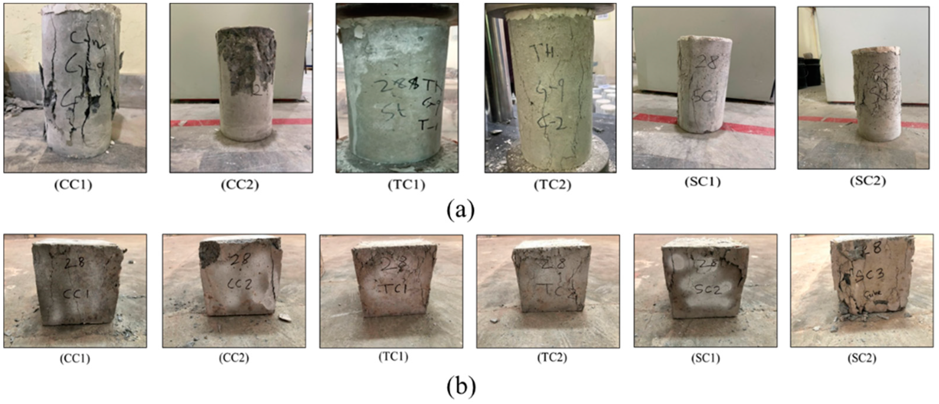
During testing, the PCC, NFT, and NFS specimens' compressive behavior was observed. The failure mode of cylinders with conventional (CC1 and CC2), threaded (TC1 and TC2), and strand (SC1 and SC2) tested specimens is depicted in Figure 5(a). The failure mode for cubes in conventional (CC1 and CC2), threaded (TC1 and TC2), and strand (SC1 and SC2) is depicted in Figure 5(b). It can be observed that during testing edges of PCC specimens were fractured, and spalling occurred, whereas NFRC specimens were noticed to be ductile. Moreover, the use of NF inhibits concrete spalling. When weak particles were present, large cracks were seen in PCC specimens; however, this experience was not seen in NFRC specimens because the fibers in the concrete specimens controlled the distribution of cracks.
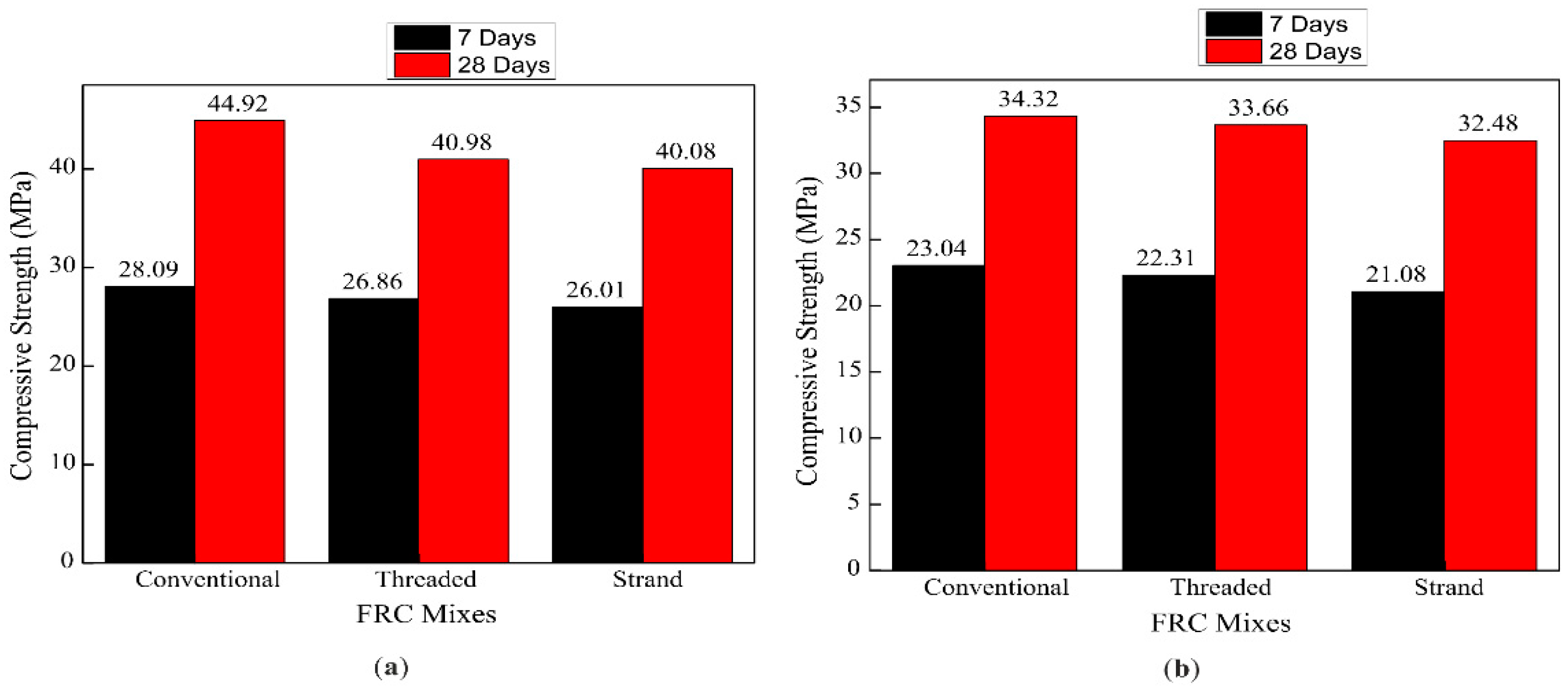
Figure 6(a) shows the experimental results of average CS for cubes. The CS of PCC, NFT, and NFS were 44.92 MPa, 40.98 MPa, and 40.08 MPa at 28 days for the cube, respectively. The CS of NFT and NFS decreased by 3.94 MPa and 4.84 MPa (8.8% and 10.8%), respectively, as compared to PCC. Figure 6(b) shows experimental results of the average CS of plain and NFRC (Plain, NFT, and NFS) for cylinders, and The CS of PCC, NFT, and NFS were 34.32 MPa, 33.66 MPa, and 32.48 MPa at 28 days for cylinder respectively. The CS of NFT and NFS decreased by 0.66 MPa and 1.84 MPa (1.9% and 5.4%), respectively, compared to PCC. Noticing the CS of the cylinder of NFT and NFS, NFT had more compressive strength than NFS, meaning that NFT was more effective. The NF, which fills the gap between aggregates having low compressive strength, could be the reason for less compressive strength in the case of NFC. The second reason for low CS, NF being a low-density material, imparts in the heterogeneousness of concrete mix design up to some extent. The third reason for the low compressive strength value was that the cement percentage in the mix design was relatively less due to the addition of nylon fibers.
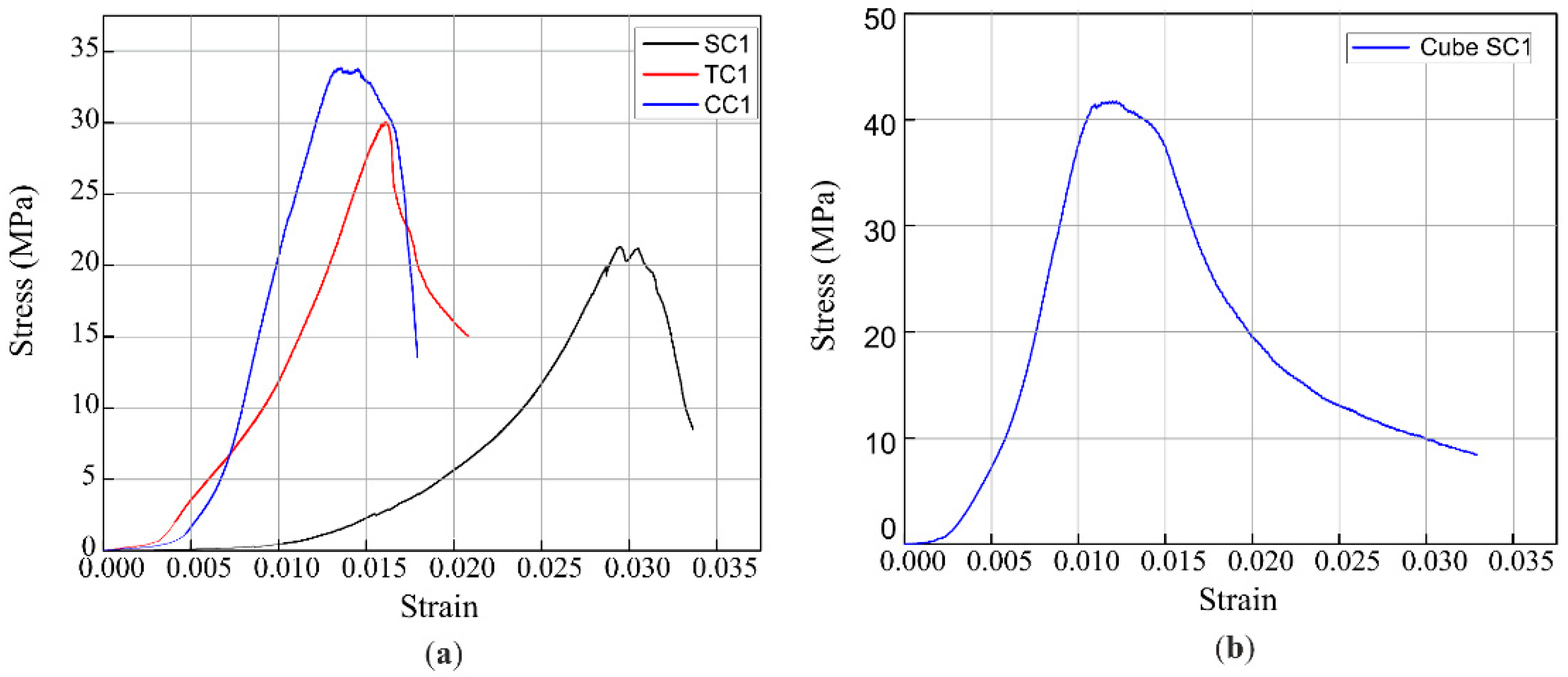
Figure 7(a) shows the cylinder's CS stress-strain curves of Palin, NFT, and NFS. The CS is the peak value of the stress-strain curve. Figure 7(b) shows the CS stress-strain curves of NFS for the cube. Strain at the highest stress was 0.03, 0.014, and 0.016 for PCC, NFT, and NFS, respectively. However, a higher dose of nylon fiber reduces the CS of FRC due to the concrete's lack of workability, which allows for greater compaction to form more pores in hardened concrete, lowering compressive strength. In case of a hazard or disaster, this increment of NFT can reduce concrete's spalling and keep concrete particles from falling. Equation (2) was used to find out the concrete's compressive strength (CS).
f c ' = P A
Where, “fc” compressive strength of concrete (N/mm2), “P” load at failure (N), and “A” area subjected to compression (mm2).

3.4. Splitting Tensile Strength (STS)

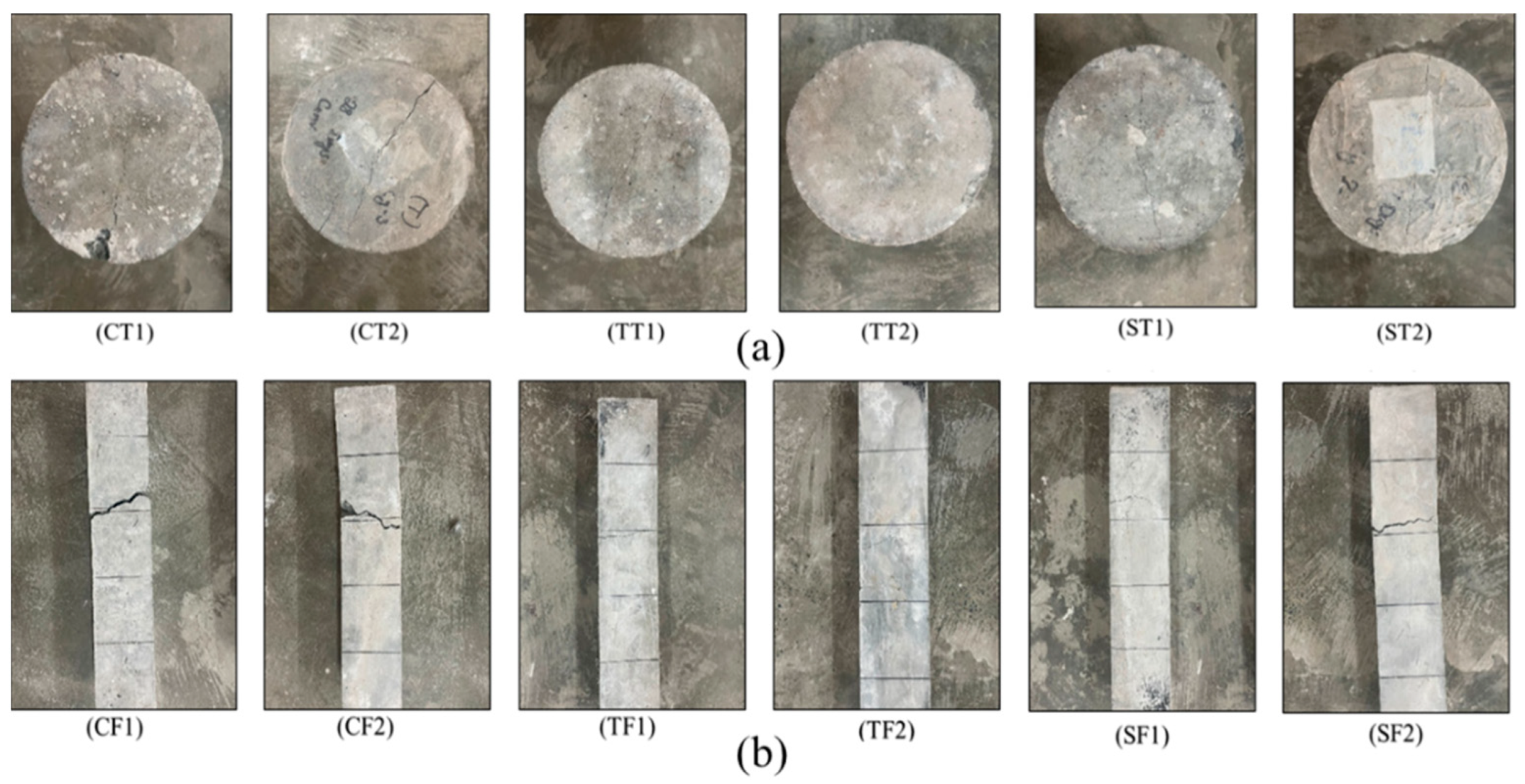
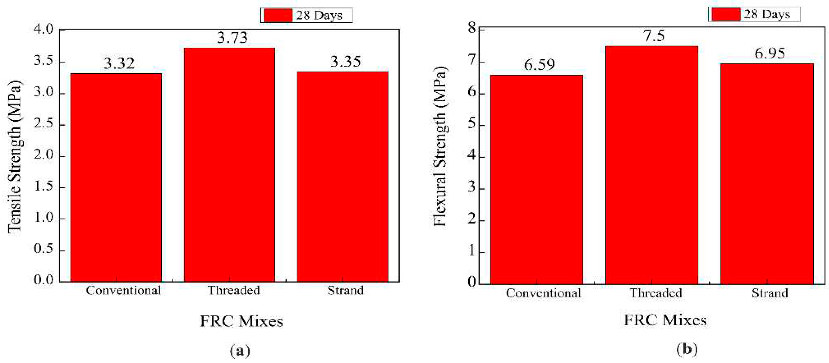
The STS of PCC, NFT, and NFS specimens were critically observed during testing. Figure 8(a) shows the failure mode of conventional (CT1 and CT2), Threaded (TT1 and TT2), and strand (ST1 and ST2) for cylinders. It was found that NFS crack behavior was more crucial than NFT crack behavior. Thus, NFT exceeded NFS in terms of effectiveness. At the maximum load, the crack sizes were increased in the concrete specimens of NFT and NFS. In PCC samples, cracks were negligible because PCC samples tested in a compression testing machine (CTM) by loading control method was 0.250 MPa/s. Figure 9(a) exhibits the experimental results of average STS of plain and fiber-reinforced concrete (Plain, NFT, and NFS). The STS of cylinders made with PCC, NFT, and NFS at 28 days was 3.32 MPa, 3.73 MPa, and 3.35 MPa, respectively. Compared to PCC, NFT showed a higher STS, with an improvement of 0.41 MPa (12.3%) over PCC. On the other hand, NFS showed a less significant improvement of 0.03 MPa (1%) over PCC. These results indicate that NFT has better resistance to crack formation in all mechanical properties of concrete. The enhanced STS of NFT and NFS over PCC is attributed to the pozzolanic reaction caused by the addition of NF. Additionally, the fibers in NFT and NFS prevent crack formation, resulting in an increase in splitting tensile strength that is more efficient than compressive strength. Research has shown that even if cracking occurs in fiber-reinforced concrete, the fibers can prevent the crack's length and width from spreading. Furthermore, the nylon fiber micro filler in NFT fills the gaps between the components of concrete, making it denser and further increasing its splitting tensile strength. Equation (3) was used to find out the concrete's splitting tensile strength (STS).
f s t = 2 P π L D
Where, “ f s t ” splitting tensile strength of concrete (N/mm2), “P” test's peak load (N), “L” cylinder specimen's length (mm), and “D” cylinder specimen's diameter (mm).

3.5. Flexural Strength (FS)

Figure 8(b) Critical crack sizes were observed and found at 125mm, 75mm, and 90 mm, in the samples of PCC, NFT, and NFS. The behavior and formation of the crack pattern of conventional (CF1 and CF2), Threaded (TF1 and TF2), and strand (SF1 and SF2) prisms were recorded through stress-strain response. Visual observation pointed out that NFRC prim samples were not broken into parts and remained intact due to nylon fiber, whereas the PCC beam samples were fully broken into two parts. When the load was further increased, the sizes of cracks were also enlarged in NFRC. This paragraph concludes that NF was well distributed and showed better results under the flexure test. The fiber pull-out mechanism can be minimized by surface treatment and using some admixture in FRC. Figure 9(b) depicts the experimental results of the average FS of plain and fiber-reinforced concrete (Plain, NFT, and NFS). PCC, NFT, and NFS FS were 6.59 MPa, 7.50 MPa, and 6.95 MPa at 28 days for the beam, respectively. The FS of NFT and NFS were enhanced by 0.91 MPa and 0.36 MPa (13.8% and 5.5%), respectively, compared to PCC. The results show that NFT has better flexural strength than NFS.
The summary of experimental results for compressive, splitting tensile, and flexural strength of concrete specimens is presented in Table 8. When comparing the stress-strain curves of NFT and NFS, it can be observed that NFT exhibited a higher maximum stress level strain of 0.014, as opposed to NFS's 0.0063. Consequently, NFT was found to be more ductile than NFS. The incorporation of fibers in concrete has been shown to improve the flexural properties of NFRC, allowing for an increase in load carrying capacity, reduction in brittle behavior, and minimization of shearing cracks. The optimal increase in flexural strength of NFRC was achieved at a 2.5% volume fraction of nylon fiber. As per ACI standard, equation (4) was used to determine concrete's flexural strength (FS), because the major cracks under flexural loading appeared near to the supports of specimens.
f r = 3 P a b d 2
Where, “ σ ” flexural strength (N/mm2), “P” test's peak load (N), “a” distance from the support to the nearest cracking point (mm), “b” and “d” cross-section of the beam (mm).

3.6. Stress-Strain ( σ ε ) behavior

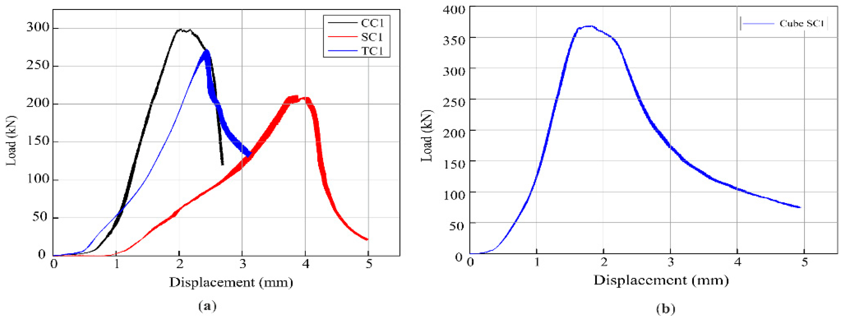
The σ ε curves of plain and fiber-reinforced concrete mixes at 28 days (non-fibrous, NFT, and NFS). Complete σ ε curves of the concrete specimens were obtained from the compressive, splitting, and flexural tests of the concrete under a universal testing machine (UTM) having a capacity of 1000 KN with a controlled displacement rate of 0.02 mm/s. Figure 10 shows the σ ε curves of CS of cylinders (CC1, TC1, SC1) and cubes (SC1) at 28 days. In CS of cylinders, strain ( ε ) at the highest stress was 0.0070, 0.0079, and 0.014 for plain (PCC), NFT, and NFS, respectively. The strain value was increased by 12.85% and 100% in the case of NFT, and NFS, respectively, compared to plain (PCC). In the compressive test, NFS has a more significant stain ( ε ) compared to NFT. This means that NFS has better elongation ability in compression compared to NFS. This increment of strain in NFRC shows that nylon fiber (NF) had better elongation ability than PCC. In case of a hazard or disaster, this increment of NFRC can reduce concrete spalling and keep concrete particles from falling.
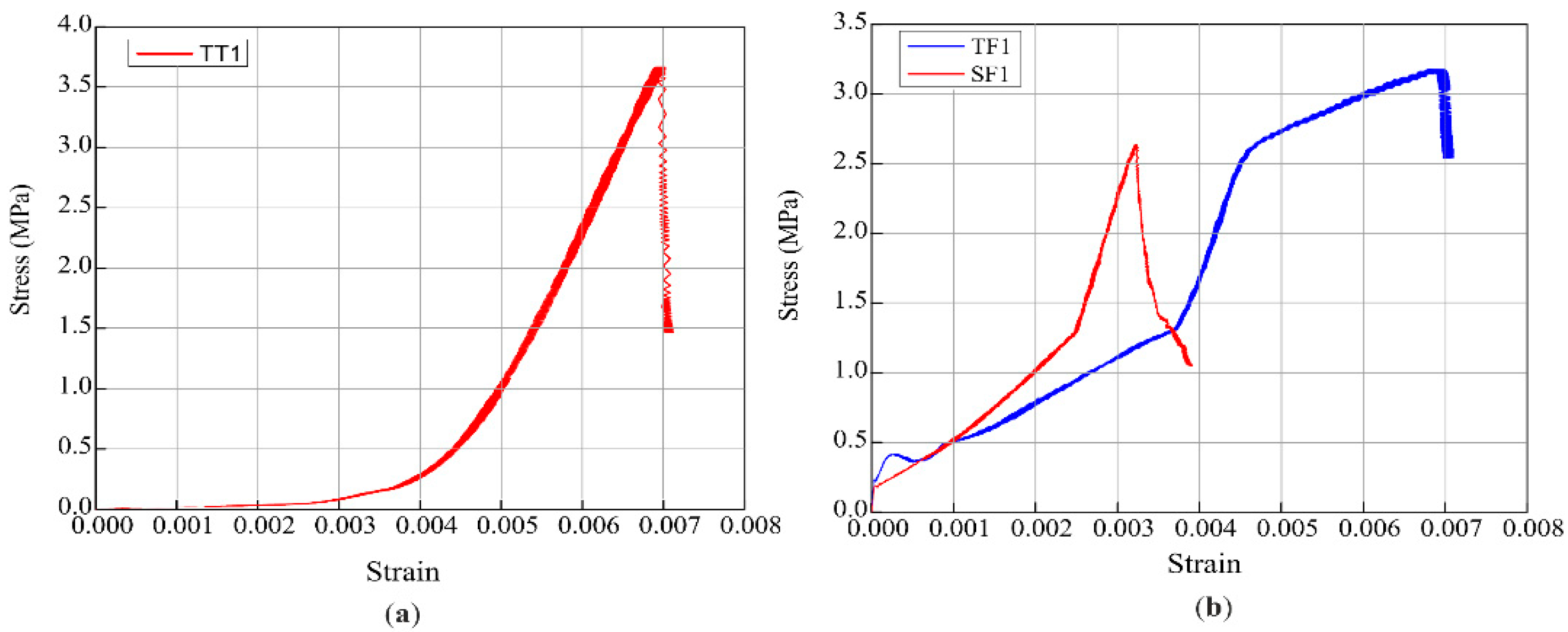
The σ-ε curves of the FS for beams (TF1, SF1) at 28 days are displayed in Figure 11. The greatest stress in the beam's FS was found to be 0.0068 for NFT and 0.0032 for NFS, respectively. NFT exhibits a greater strain (ε) in the flexural test than NFS. Consequently, it was determined that under flexural stress, NFT has a greater capacity for elongation than NFS. Additionally, the results showed that all of the concrete specimens had ultimate load values that were higher than plain (PCC).
The experimental and theoretical modulus of elasticity for the mixes (Plain, NFT, NFS) are shown in Table 9. The equation (5) was used to calculate the theoretical modulus of elasticity ( E s ). The table shows the E s value of compressive (CC1, TC1, SC1), splitting (TT1), and flexural (TF1, SF1) strength. The theoretical equation:
E c = 0.043 w 1.5 f c '
Where f c ' compressive strength of concrete in MPa and “w” concrete density have a value of 2300 kg/m3.

3.7. Ductility

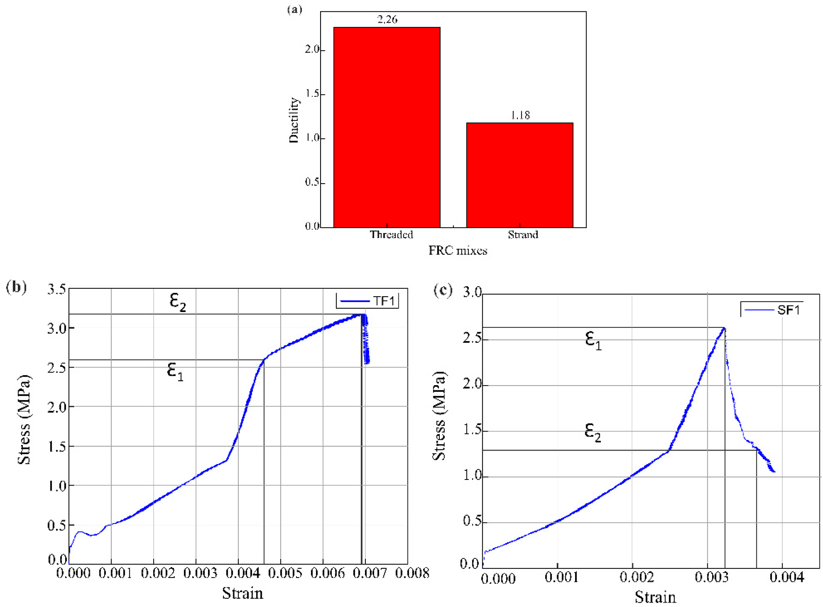
The ductility of concrete is an essential parameter for the analysis of concrete structures. Ductility is the material's degree of capability to assist significant plastic deformation before failure. Ductility is the ratio between the deflection at the yield point and the deflection at failure. Concrete is a brittle material that does not give a warning before failure for any construction materials. Table 10 shows the FS of fiber-reinforced concrete mixes (NFT, NFS). The ductility of NFT and NFS was 2.26 and 1.88, respectively. Figure 12(a) shows the graphical analysis of FS of fiber-reinforced concrete mixes (NFT, NFS). In fiber-reinforced concrete mixtures, the diminish of ductility is 16.8%. Therefore, NFT had better resistance ability and elongation than NFS. Equation (6) and Figure 12(b, c) were used to find ductility.
μ = Ɛ 2 Ɛ 1
Where "Ɛ2" stress-strain data from the second peak and "Ɛ1" stress-strain data from the first peak.

4. Conclusion

The current study investigated the axial compressive, splitting tensile, and flexural behavior of normal strength of nylon fibers reinforced (NFR) cementitious composites. The nylon fibers used in this study were of two types: NFT and NFS. The primary factors studied include W/C ratio, admixture, fiber content, and combinations. Based on the experimental results and evaluation, the leading conclusions were drawn as follows:
  • Workability, density, compressive, splitting, and flexural strength tests on NFRC were examined upon adding nylon fiber to PCC. The addition of nylon fiber in PCC enhanced the density of NFT by 0.03%.
  • The cracking resistance of PCC was improved up to 12.85% with the addition of nylon fiber and the ductility of NFT was enhanced by 16.8% compared to NFS.
  • The incorporation of nylon fibers (2.5%) volume fraction of coarse aggregates in the concrete mix had a 1-6% effect on CS of NFT and NFS. The reduction in CS of NFT and NFS was 1.9% and 5.4%, respectively.
  • NFRC specimens cast with 2.5% of NFS and NFT improved STS by 12.3% and 1%, respectively, compared to the PCC with 0% addition of NF.
  • Both types of fibers (NFS and NFT) significantly influenced (5-14%) the FS of NFRC. An improvement of 13.8% and 5.5% was observed in the FS of NFT and NFS.
  • The experimental results showed that NFT outperform by 13.05% than that of NFS.

Recommendation

It is recommended that related research be done to examine the impact performance and durability of fibrous concrete made using nylon fiber with different diameters. The hydration process must be ensured through appropriate curing techniques, acceptable quality control procedures, and structural maintenance. Nylon fibers could be studied in various lengths, proportions, and high-strength design mixtures for better results. It is essential to investigate nylon fiber in various mix combinations to explore their applicability in reducing dry shrinkage and creep deformation.

Author Contributions

Suliman Khan: Conceptualization, Methodology, Data curation, Visualization, Writing – original draft, Writing – review & editing. Elena Ferretti: Investigation, Visualization, Data curation, Review analysis & editing. Shahzad Ashraf: Review analysis & editing, Visualization.

Data Availability Statement

All data used during the study appear in the submitted article.

Acknowledgments

The authors would like to acknowledge the support of technical staff of Civil engineering Laboratory, Tianjin University, China for providing financial support and testing facilities.

Conflicts of Interest

The authors declare that the research conducted in this study has no conflicts of interest.

References

  1. Srinivas Allena, Craig M. Newtson, Ultra-High Strength Concrete Mixtures Using Local Materials, J. Civ. Eng. Archit. 5 (2011). [CrossRef]
  2. K. Kishore, N. Gupta, Application of domestic & industrial waste materials in concrete: A review, Mater. Today Proc. 26 (2020) 2926–2931. [CrossRef]
  3. J. Ahmad, O. Zaid, C.L.-C. Pérez, R. Martínez-García, F. López-Gayarre, Experimental Research on Mechanical and Permeability Properties of Nylon Fiber Reinforced Recycled Aggregate Concrete with Mineral Admixture, Appl. Sci. 12 (2022) 554. [CrossRef]
  4. S. Khan, S. Ashraf, S. Ali, K. Khan, Experimental investigations on the mechanical properties and damage detection of carbon nanotubes modified crumb rubber concrete. J. Build. Eng. 75 (2023) 106937. [CrossRef]
  5. J. Xu, S. Ashraf, S. Khan, X. Chen, A. Akbar, F. Farooq, Micro-cracking pattern recognition of hybrid CNTs/GNPs cement pastes under three-point bending loading using acoustic emission technique. J. Build. Eng. 42 (2021) 102816. [CrossRef]
  6. Noushini, F. Aslani, A. Castel, R.I. Gilbert, B. Uy, S. Foster, Compressive stress-strain model for low-calcium fly ash-based geopolymer and heat-cured Portland cement concrete, Cem. Concr. Compos. 73 (2016) 136–146. [CrossRef]
  7. S. Singh, G.D. Ransinchung, P. Kumar, Effect of mineral admixtures on fresh, mechanical and durability properties of RAP inclusive concrete, Constr. Build. Mater. 156 (2017) 19–27. [CrossRef]
  8. S. Ashraf, S. Khan, V.K. Oad, Microcracking monitoring and damage detection of graphene nanoplatelets-cement composites based on acoustic emission technology, Case Stud. Constr. Mater. 18 (2023) e01844. [CrossRef]
  9. E. Ferretti, A discussion of strain-softening in concrete, Int. J. Fract. 126 (2004) L3–L10. [CrossRef]
  10. E. Ferretti, Shape-effect in the effective laws of plain and rubberized concrete, Comput. Mater. Contin. 30 (2012) 237–284.
  11. C.A.K.R.P.P.R.& L.S.K. P. Ganesh Prabhu, Study on Utilization of Waste Pet Bottle Fiber in Concrete, IMPACT Int. J. Res. Eng. Technol. (IMPACT IJRET). 2 (2014) 233–240.
  12. W. Wang, A. Shen, Z. Lyu, Z. He, K.T.Q. Nguyen, Fresh and rheological characteristics of fiber reinforced concrete——A review, Constr. Build. Mater. 296 (2021) 123734. [CrossRef]
  13. C. Zhao, Z. Wang, Z. Zhu, Q. Guo, X. Wu, R. Zhao, Research on different types of fiber reinforced concrete in recent years: An overview, Constr. Build. Mater. 365 (2023) 130075. [CrossRef]
  14. S. Hedjazi, D. Castillo, Relationships among compressive strength and UPV of concrete reinforced with different types of fibers, Heliyon. 6 (2020) e03646. [CrossRef]
  15. D.S. Ozsar, F. Ozalp, H. Dilsad Yilmaz, B. Akcay, Effects of nylon fibre and concrete strength on the shrinkage and fracture behaviour of fibre reinforced concrete, in: Strain-Hardening Cem. Compos. SHCC4 4, Springer, 2018: pp. 188–194.
  16. K. Cui, L. Xu, T. Tao, L. Huang, J. Li, J. Hong, H. Li, Y. Chi, Mechanical behavior of multiscale hybrid fiber reinforced recycled aggregate concrete subject to uniaxial compression. J. Build. Eng. 71 (2023) 106504. [CrossRef]
  17. S. Ashraf, M. Rucka, Microcrack monitoring and fracture evolution of polyolefin and steel fibre concrete beams using integrated acoustic emission and digital image correlation techniques, Constr. Build. Mater. 395 (2023) 132306. [CrossRef]
  18. S. Yin, R. Tuladhar, F. Shi, M. Combe, T. Collister, N. Sivakugan, Use of macro plastic fibres in concrete: A review, Constr. Build. Mater. 93 (2015) 180–188. [CrossRef]
  19. Y. Choi, R.L. Yuan, Experimental relationship between splitting tensile strength and compressive strength of GFRC and PFRC. Cem. Concr. Res. 35 (2005) 1587–1591. [CrossRef]
  20. L. Sun, Q. Hao, J. Zhao, D. Wu, F. Yang, Stress strain behavior of hybrid steel-PVA fiber reinforced cementitious composites under uniaxial compression, Constr. Build. Mater. 188 (2018) 349–360. [CrossRef]
  21. L. Rizzuti, F. Bencardino, Effects of fibre volume fraction on the compressive and flexural experimental behaviour of SFRC, Contemp. Eng. Sci. 7 (2014) 379–390. [CrossRef]
  22. T. Ayub, S.U. Khan, A. Ayub, Analytical model for the compressive stress–strain behavior of PVA-FRC, Constr. Build. Mater. 214 (2019) 581–593. [CrossRef]
  23. T. K, S.S. R, V. P, S. V, Study on characteristics of textile fiber reinforced concrete, Int. J. Appl. Sci. 8 (2016) 41–57.
  24. H. Jahangir Qureshi, J. Ahmad, A. Aljabr, N. Garcia-Troncoso, Review on characteristics of concrete reinforced with nylon fiber, J. Eng. Fiber. Fabr. 18 (2023) 1–15. [CrossRef]
  25. A. Zia, M. Ali, Behavior of fiber reinforced concrete for controlling the rate of cracking in canal-lining, Constr. Build. Mater. 155 (2017) 726–739. [CrossRef]
  26. D. Ra B, K. Zhimo, P. Tigga, C. Bhutia, Y. Bhutia, D. Pradeep, V.P. Darshini, Experimental Study on Concrete Using Zygote Encastment Powder, Crushed Groundnut Shell and Nylon Fiber as a Partial Replacement for Materials, J. Crit. Rev. 7 (2020) 1326–1333. [CrossRef]
  27. P.S. Song, S. Hwang, B.C. Sheu, Strength properties of nylon- and polypropylene-fiber-reinforced concretes, Cem. Concr. Res. 35 (2005) 1546–1550. [CrossRef]
  28. M. Najafi, L. Nasri, R. Kotek, High-performance nylon fibers, in: Struct. Prop. High-Performance Fibers, Elsevier, 2017: pp. 199–244. [CrossRef]
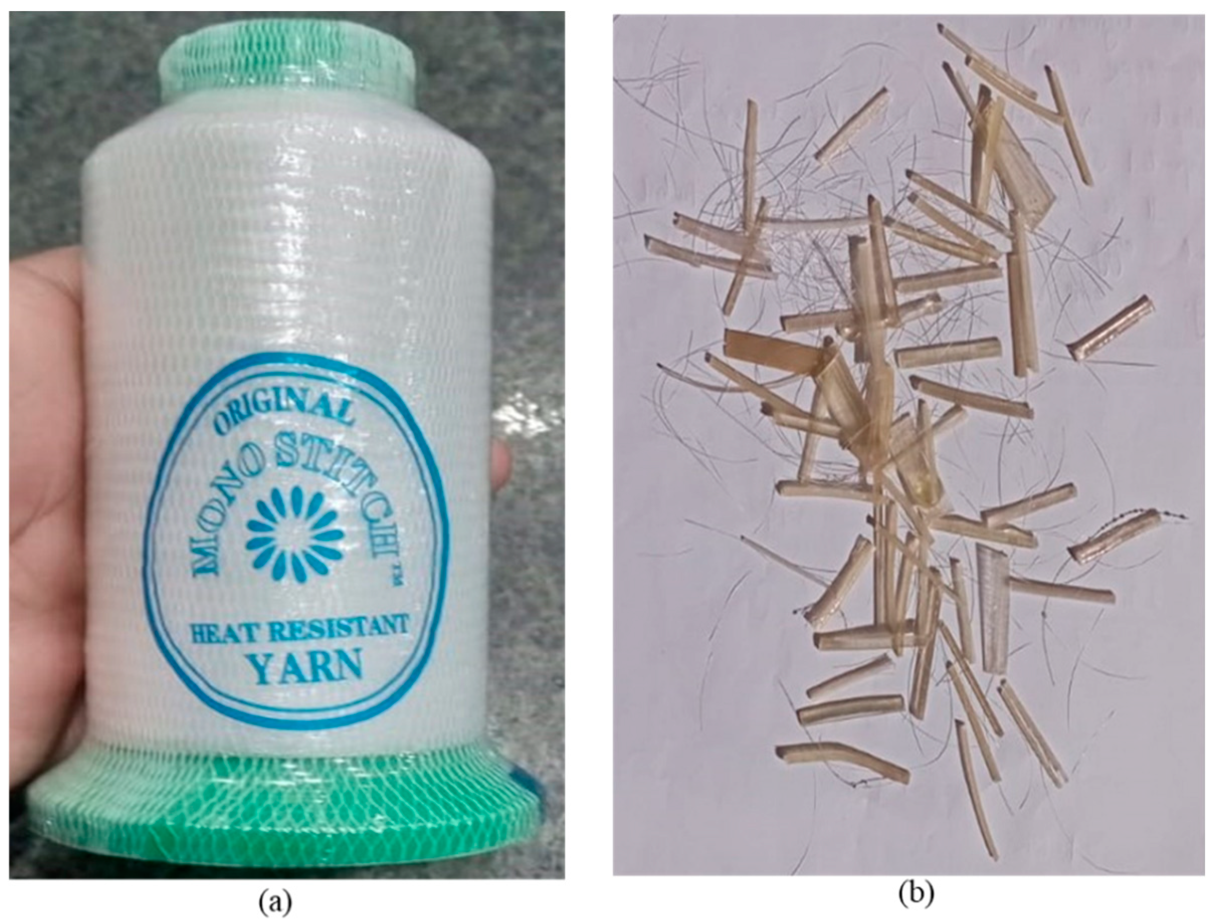
Figure 1. Nylon fibers: (a) Nylon fibers in yarn form; (b) NFT and NFS.
Preprints 91606 g001
Figure 2. Mixing procedure for casting of specimens.
Preprints 91606 g002
Figure 3. Mechanical testing of the hardened specimens: (a) compression test setup for the cylinder; (b) compression test setup for cube; (c) splitting tensile test setup; and (d) flexural test setup.
Preprints 91606 g003
Figure 4. Densities of NFRC.
Preprints 91606 g004
Figure 5. The failure mode of compression test for cylinders and cubes: (CC) failure mode of conventional compressive; (TC) failure mode of threaded compressive; and (SC) failure mode of strand compressive.
Preprints 91606 g005
Figure 6. Compressive strength of plain and fiber-reinforced concrete mixes; (a) Cubical strength; (b) Cylindrical strength.
Preprints 91606 g006
Figure 7. Stress-strain curve for compression test: (a) CS stress-strain curves of Palin, NFT, and NFS for the cylinders; and (b) CS stress-strain curves of NFS for the cubes.
Preprints 91606 g007
Figure 8. The failure mode of splitting tensile and flexural test for cylinders and prisms: (a) (CT) failure mode of conventional tensile; (TT) failure mode of threaded tensile; and (ST) failure mode of strand tensile; (b) (CF) failure mode of conventional flexural; (TF) failure mode of threaded flexural; and (SF) failure mode of strand flexural.
Preprints 91606 g008
Figure 9. Mechanical strengths of plain and NF-fiber reinforced concrete mixes; (a) Splitting tensile strength; and (b) Flexural strength.
Preprints 91606 g009
Figure 10. Load displacement curve for compression test: (a) CS load-displacement curves of Plain, NFT, and NFS for the cylinder; and (b) CS load-displacement curves of NFS for the cubes.
Preprints 91606 g010
Figure 11. Stress-strain curve for splitting tensile and flexural test: (a) STS stress-strain curves of NFT for the cylinder; and (b) FS stress-strain curves of NFT and NFS for the prisms.
Preprints 91606 g011
Figure 12. Ductility of fiber-reinforced mixes of prisms: (a) Comparison between NFT and NFS; (b) Stress-strain curve of TF1; and (c) Stress-strain curve of SF1.
Preprints 91606 g012
Table 1. Chemical composition of ordinary Portland Cement (OPC) Type-1.
Chemical composition CaO SiO2 MgO Al2O3 Fe2O3 SO3
Percentages (%) 68.4 19.5 1.3 4.6 1.2 3.1
Table 2. Quantities of Materials.
Materials Quantity (Kg/m3)
Cement 540
Sand 742.44
Coarse aggregates 849.3
Water 239.3
Table 3. Properties of nylon fiber (NF).
Fiber type NFT
Diameter
[mm]
NFS
Diameter
[mm]
Fiber
Length
[mm]
Specific
gravity
Tensile
Strength
[MPa]
Elastic
Modulus
[MPa]
Water
Absorption
[%]
Nylon 0.14 2 25 1.14 827.4 5300 2.8-5.0
Table 4. Mix proportions of plain, NFT, and NFS mixes of the cylinder for compression and splitting tensile properties.
Description Abb** Cement
(kg/m3)
Coarse
Aggregates(kg/m3)
Fine
Aggregates
(kg/m3)
Nylon
Fibers
(g)
SP*(ml)
Plain CC/CT 3.48 5.85 5.16 0 34.8
NFT TC/TT 3.48 5.76 5.16 91 34.8
NFS SC/ST 3.48 5.76 5.16 91 34.8
Note: SP* = Superplasticizer (10 mL per 1 kg cement) and Abb** = Abbreviation.
Table 5. Mix proportions of plain, NFT, and NFS mixes of the cube for compression property.
Description Abb** Cement
(kg/m3)
Coarse
Aggregates
(kg/m3)
Fine
Aggregates
(kg/m3)
Nylon
Fiber
(g)
SP*
(ml)
Plain CC 2.53 4.23 3.75 0 25.3
NFT TC 2.53 4.17 3.75 58 25.3
NFS SC 2.53 4.17 3.75 58 25.3
Table 6. Mix proportions of Plain, NFT, and NFS mixes of the Beam for Flexural.
Description Abb** Cement(kg/m3) CoarseAggregates(kg/m3) FineAggregates(kg/m3) Nylon Fiber(g) SP*(ml)
Units - (kg/m3) (kg/m3) (kg/m3) (g) (ml)
Plain CF 3.08 5.17 4.57 0 30.8
NFT TF 3.08 5.09 4.57 80 30.8
NFS SF 3.08 5.09 4.57 80 30.8
Table 7. W/C ratio, slump, and density of PCC, NFT, and NFS.
Concrete type Water cement ratio Slump (mm) Density (kg/m3)
PC 0.4 collapsed 1146.4
NFT 0.4 zero 1176.4
NFS 0.4 collapsed 1092.5
Table 8. Experimental results of plain and NF-fiber reinforced concrete mixes.

Characteristics
Specimen

size

Day
NFRC Mix
Plain NFT NFS
Compressive strength
(MPa)
150×150×150(mm) 28 44.92 40.98 40.08
Compressive strength
(MPa)
150×300 (mm) 28 34.32 33.66 32.48
Splitting tensile strength (MPa) 150×300 (mm) 28 3.32 3.73 3.35
Flexural strength (MPa) 100×100×500 (mm) 28 6.59 7.50 6.95
Table 9. Comparison of elastic modulus (Es) theoretically and experimentally.
Sr. No. Concrete type Stress Strain Theoretically
(Es)
Experimentally
(Es)
Units
1 CC1 33.86 0.0070 27349 4837 (MPa)
2 TC1 30.08 0.0079 25777 3807 (MPa)
3 SC1 21.31 0.014 21696 1522 (MPa)
Table 10. Ductility of fiber-reinforced mixes NFT and NFS of the beam.
Sr. No. Concrete Type Ductility Reduction
1 TF1 2.26 -
2 SF1 1.88 16.8%
Disclaimer/Publisher’s Note: The statements, opinions and data contained in all publications are solely those of the individual author(s) and contributor(s) and not of MDPI and/or the editor(s). MDPI and/or the editor(s) disclaim responsibility for any injury to people or property resulting from any ideas, methods, instructions or products referred to in the content.
Copyright: This open access article is published under a Creative Commons CC BY 4.0 license, which permit the free download, distribution, and reuse, provided that the author and preprint are cited in any reuse.
Prerpints.org logo

Preprints.org is a free preprint server supported by MDPI in Basel, Switzerland.

Subscribe

© 2024 MDPI (Basel, Switzerland) unless otherwise stated