Preprint
Article

Mechanics of A Thin-Walled Torus Snap Fit

Altmetrics

Downloads

97

Views

68

Comments

0

This version is not peer-reviewed

Submitted:

08 November 2023

Posted:

09 November 2023

You are already at the latest version

Alerts
Abstract
Snap-fit is a commonly used jointing/connention mechanism, and its easy installation and difficult removal are the result of the coordinated interaction between friction, geometric shape, and elasticity. This paper presents a detailed study on the assembly/disassembly forces of thin-walled torus snap-fit through finite element simulation, experimental testing, and data fitting of approximate analytical solutions. The research reveals that the non-zero Gaussian curvature of the torus has a significant impact on the mechanical performance of the torus snap fit. The findings in this study are of great significance for future design of high-performance structural connections.
Keywords: 
Subject: Engineering  -   Mechanical Engineering

1. Introduction

Any physical structure is composed of components that are interconnected, in particular prefabricated structures. In engineering, connections between components are often weak areas. Unreasonable connection methods can easily reduce the strength of components, resulting in unpredictable failure modes. While current research has primarily focused on various structural elements such as beams, plates, and shells, less attention has been given to their connections. Even when considering connections, they are often simplified as rigid or elastic connections. Furthermore, the structural form and three-dimensional characteristics of the connecting parts themselves are often overlooked. In reality, the quality of the connection is crucial not only for maintaining the integrity of the structure but also for absorbing significant amounts of energy, thereby greatly improving the toughness of the structure [1,2]. However, designing an effective connection poses a scientific and technical challenge.
In common thin shells, due to the Gaussian curvature of the complete torus changing from positive in the outer ring to negative in the inner ring, it exhibits special geometrical properties as shown in Figure 1. The second author has done systematic research on linear and nonlinear symmetrical deformation [3,4,5,6,9,11], Flügge’s problem [7,12] and Gol’denveizer’s problem [8,13,14] of elastic torus, and other scholars have done some research on elliptic toroidal shells [15], semi-toroidal shell [16], multi-shell toroidal pressure vessels [17], weaving shells with naturally in-plane curved ribbons [18], it was found that the specific strength of the inner torus is greater than that of the outer torus. Due to this characteristic of torus, they have a wide range of applications, one of which is the production of elastic components. Of course, they can also be made into elastic snap fits. There have been relevant studies on beam-shaped snap fits [19,20,22], cylindrical snap fit [23,24,26] and spherical snap fit [25]. Yoshida et al. was the first study on cylindrical snap fit [23] and followed up by Guo and Sun [24,26], and Guo and Sun was the first study on spherical snap fit[25]. However, to the best of the author’s knowledge, there has been no research conducted on thin-walled torus snap fit. From both scientific and practical perspectives, it is necessary to conduct research on thin-walled torus snap fit as it is a common method of connection.
Snap fit is a versatile and efficient connection method of joining two or more components together without the need for additional connection such as screws or adhesives. It is a simple and efficient way to assemble products, allowing for easy disassembly and reassembly if necessary. Its widespread use in various industries highlights its effectiveness as a reliable joining technique. The snap fit technique involves designing specific features on the mating parts that interlock when pressed together. These features, known as snaps or hooks, provide a secure and reliable connection between the components. The snaps can be designed in various forms, such as cantilever, annular, or torsional, depending on the desired strength and flexibility of the joint. One of the key advantages of snap fit is its cost-effectiveness. By eliminating the need for additional hardware, it reduces manufacturing costs and simplifies the assembly process. Snap fit also offers design flexibility, as it allows for the creation of complex shapes and geometries that would be difficult to achieve with traditional fastening methods. Furthermore, snap fit connections are often reversible, enabling easy maintenance and repair. This feature is particularly beneficial in industries where frequent disassembly and reassembly are required, such as electronics or automotive. However, it is important to consider the material properties and design considerations when implementing snap fit joints. Factors such as material selection, wall thickness, friction, and snap dimensions must be carefully evaluated to ensure proper functionality and durability [19,20].
The snap fit appears everywhere in our daily lives, from pen cap, Lego, zipper, water pipe clamp, etc.[19,20], to receptor ligand interaction in biochemistry [27,28], and spacecraft docking [29], all use the principle of snap fit [19,20]. The snap fit seems simple, but it reveals how an operational asymmetry of snap fits (i.e., easy to assemble but difficult to disassemble) emerges from an exquisite combination of geometry, friction and elasticity [19,20,21,22,23,24,25,26,30,31,32,33,34,35,36,37,38,39].
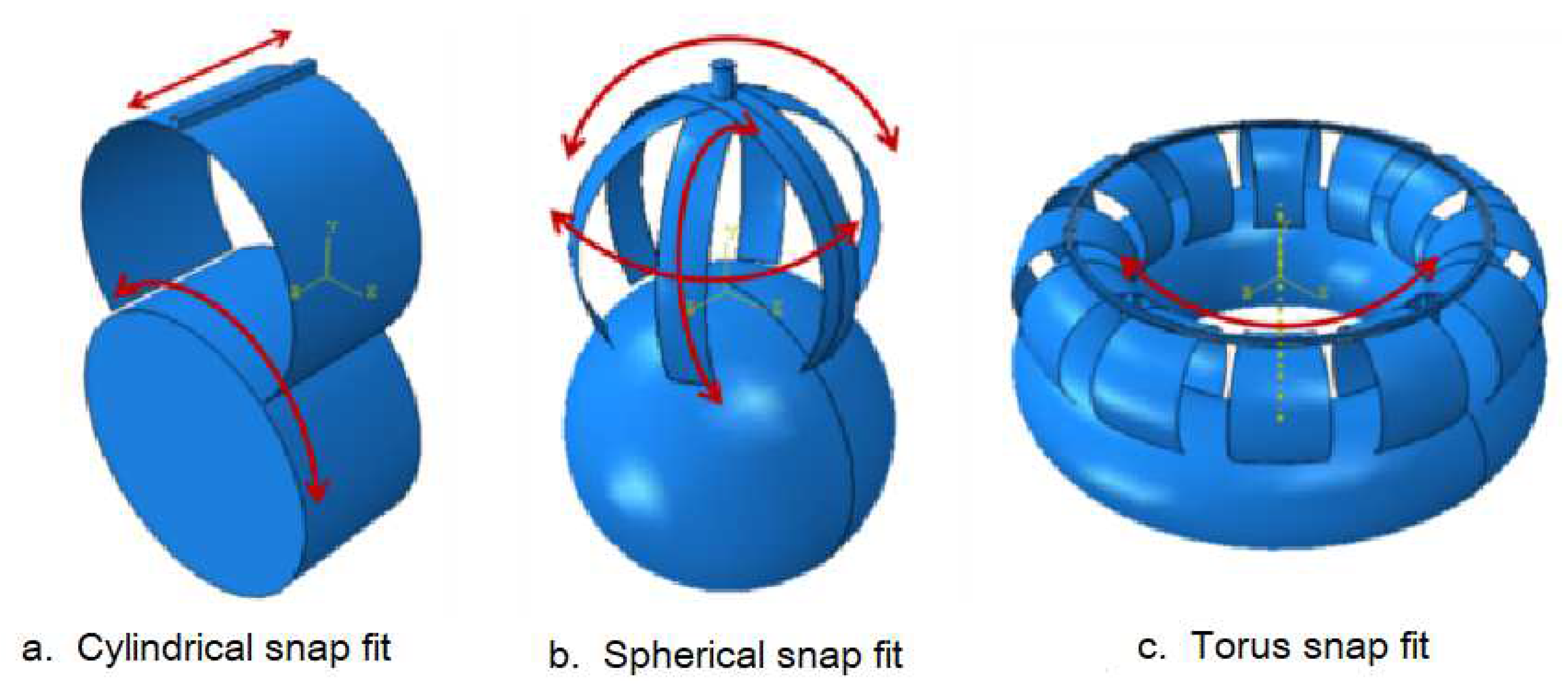
In our previous studies [24,25,26], we have revealed the general law of physical asymmetry between the assembling force and the disassembling force of the snap fit through the cylindrical snap fit [23,24] and the spherical snap fit [25]. However, due to the different demand for the snap fit, the freedom of assembly of different snap fit is different, which also prompts us to study various snap fit shapes. Common snap fit types include cantilever snap fit with [19,20,22], cylindrical snap fit [23,24,26], spherical snap fit [25], torus snap fit, etc., as shown in Figure 2.
Different types of snap fits have different feature, for example, the cylindrical snap fit has 2 degrees of freedom, the spherical snap fit has 3 degrees of freedom after assembly, and the torus snap fit has only 1 degree of freedom after assembly. Therefore, in order to meet the assembly requirements of different snap fits, it is necessary to carry out research on assembly and disassembly of different types of snap fits.
Among many snap fit types, the torus snap fit is widely used in connection parts that need to be fastened without rotation because it has only 1 degree of freedom. As can be seen from the comparison of spherical snap fit[25] and cylindrical snap fit [23,24,26], the Gaussian curvature has a significant impact on the assembly-disassembly force [23,24,25,26] because the Gaussian curvature of the torus snap fit is not zero while the Gaussian curvature of the cylindrical buckle is zero [23,25,26], we can foresee that the torus snap fit should have a greater assembly/disassembly force than the corresponding cylindrical snap fit. What is the actual situation, further detailed analysis and research on torus snap fit are still needed. However, to the best of the author’s knowledge, no articles discussing the mechanics of the torus snap fit have been seen yet.
The rest of this paper is organized as follows. In Section 2, Finite element analysis of assembly/disassembly force is carried out. In Section 3, Experimental analysis of assembly/disassembly force is conducted. In Section 4, Theoretical prediction of assembly/disassembly force is formulated by data fitting. In Section 5, Conclusions are drawn and future perspectives are foreseen.

2. Assembly/disassembly force finite element analysis of a single torus snap fit

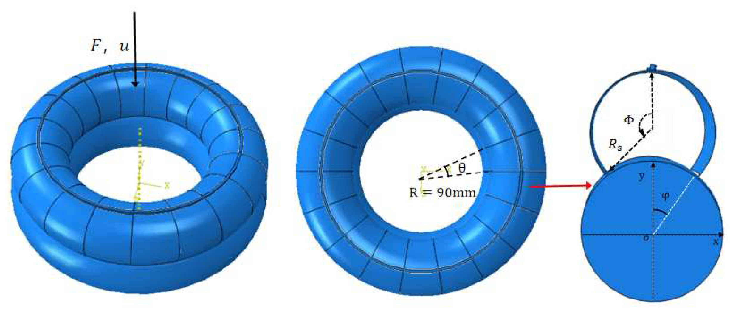
We consider a open torus with radius R s and thickness t as shown in Figure 3, which is pushed onto a surface of a rigid torus with radius R c . The shell either clutches the rigid torus via a snap fit or buckles on the rigid torus surface depending on the geometrical parameters of the torus shell and torus rigid. We divide a complete torus shell into several sections of equal angles, and take out one of them as a snap fit. In this study, we processed the full torus snap fit and set the angle to be θ = 20 o .
For a single torus snap fit, whose finite element model is shown in Figure 4. In this FEM model, Abaqus/Standard general solver module is adopted.The contact is general contact, the normal contact is hard contact, and penetration is not allowed, and the normal direction is set as penalty. The mesh cell type of the snap-fit is S4R, and the size is set to global ruler. Torus rigid is set to rigid body.
We used ABAQUS code to calculate the 20o torus snap fit with 10 different opening angles. The simulation process was divided into two steps: assembly and disassembly. During the assembly process, the shell moved down at a speed of 5 mm/s until the top of the shell touched the torus surface. After 1 s, the housing moved up at the same speed of 5 mm/s (disassembly process). The FEM results are shown in Table 1.
Due to the interaction of elasticity, friction and geometry of the snap fit, it can be seen from the finite element simulation results that the snap fit with different parameters Φ , α , μ corresponds to different physical phenomena, namely sliding installation and jumping installation [23,24,25]. Accordingly, the snap fit deformation phenomena can be divided the torus snap fit into two types: Type I snap-fit (having small deflection before snap fit) and Type II snap-fit (having large deflection before snap fit).
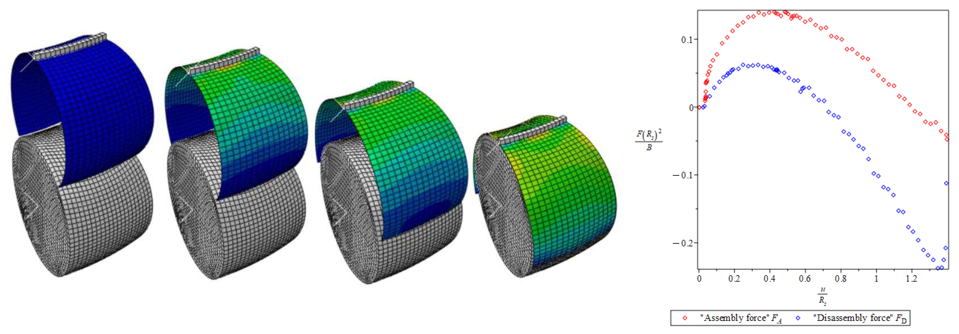
The main feature of type I snap-fit’s deformation is that the shell only deflects moderately during the assembly process, and then fits spontaneously. The assembly process of Type I torus snap fit is shown in Figure 5.
The main feature of the type II snap-fit is that the shell will be strongly squeezed to form an M-shaped structure during the clamping process, and then it will suddenly jump out and cooperate at the critical compression point, which has a certain energy absorption effect [23,24,25]. The assembly process of Type II torus snap fit is shown in the Figure 6.
It can be seen that the Type I and II torus snap fit has totaly different assembly and disassembly force profile, which can be used for energy absorbing when design snap fit metamterials or damping devices [39].

3. Experimental analysis of a single component torus snap fit

In order to validate the correctness of the finite element results of the 20 torus snap fit, the numerical comparison between the simulation and the experiment is carried out. The experimental model is fabricated by 3D printer: Stereo lithography Appearance. The snap-fit with opening Angle Φ = 2.3 rad and thickness t = 1 mm was prepared for experiment. The material is UV curable Resin. The assembly experiment of type I snap-fit was carried out by microcomputer controlled electronic universal testing machine (E43.1044), as shown in Figure 7.
We established a finite element model according to the above model parameters, and drew a comparison diagram between the simulation data of the model and the experimental data, as shown in the Figure 7. According to the Figure 7, we can intuitively see that the two curves are basically consistent, and the error does not exclude factors such as friction (friction coefficient is taken from friction experiment). This further proves the correctness of our finite element simulation.

4. Assembly/disassembly force theoretical prediction of a single torus snap fit

For given friction μ and radius ratio α , the design of snap fit is to predict the assemly/disassemly force by adjusting opening angle Φ . It means that it would be better to have a formulae of assemly/disassemly force in terms of the opening angle Φ .
The torus snap fit is difference from the cylindrical snap fit, due to the Gaussian curvature and angle θ of the sectional torus. To formulate theoretical prediction of assembly and disassembly force of a single torus snap fit is very difficulty due to the complicate nature of torus mechanics [3,4,5,6,9,11]. Nevertheless, we can borrow some theoretical results from cylindrical snap fit obtained by Yoshida eta al. [23] and later modified by Guo and Sun [24].
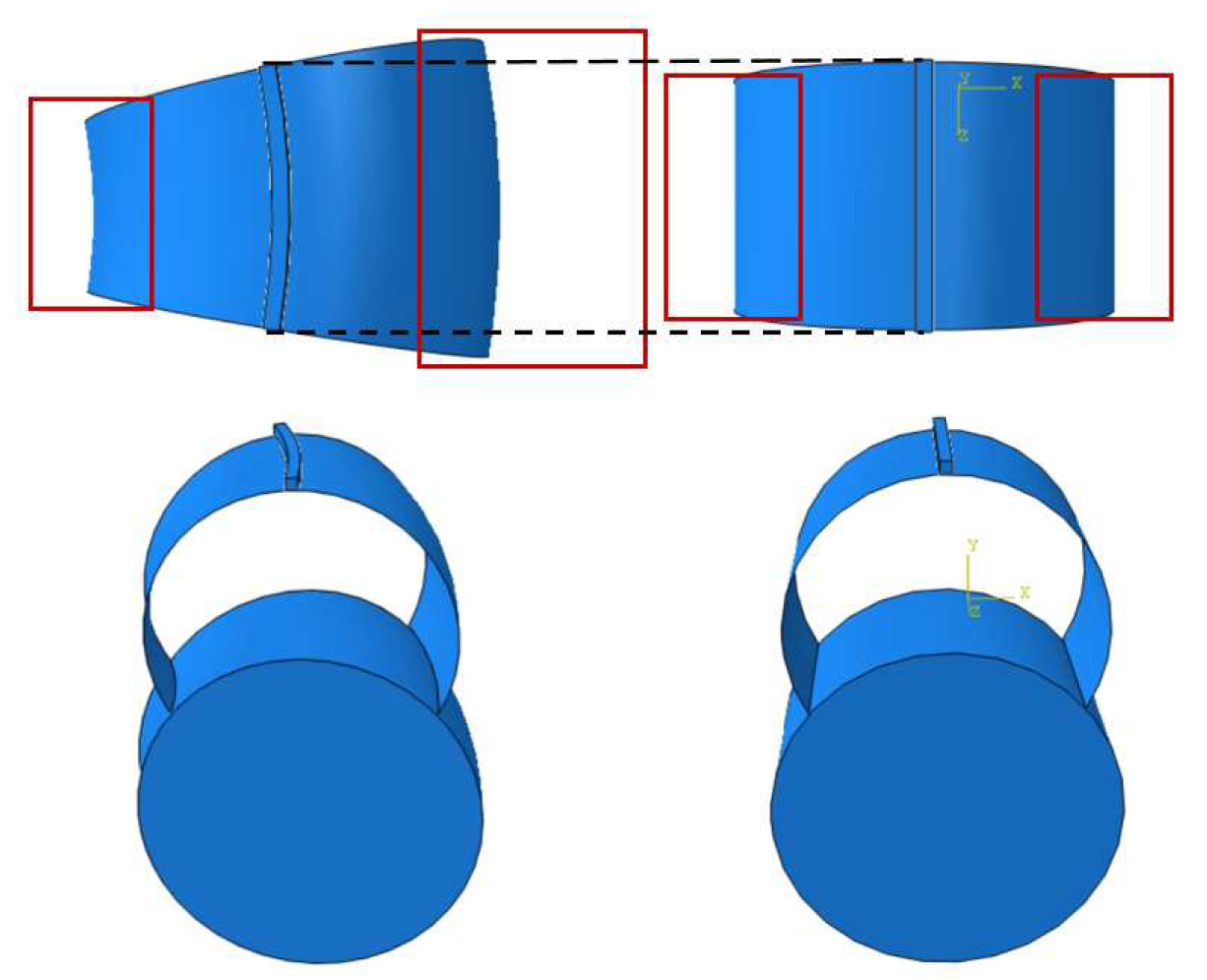
In order to use the results of Yoshida eta al. [23], we consider a single torus snap fit as an equivalent cylindrical snap fit as shown in Figure 8.
We compare the assembly force and disassembly force between Type I 20o torus snap fit and its corresponding equivalent cylindrical snap fit of type I as shown in Figure 9.
It is obvious that the assembly force F A and disassembly force F D of 20 torus snap fit are obviously higher than that of cylindrical snap fit, due to the influence of curvature. The good thing is that their curve profile has same trend. Therefore, under the condition of small deformation (type I snap-fit), 2.0 < Φ < 2.6 rad, we fit the scatter diagrams of assembly force-opening angle and disassembly force-opening angle, as shown in Figure 9. Since no analytical solutions have been obtained for the torus snap fit, the formulae of cylindrical snap fit derived by [23,24] will be used as basic fitting function.
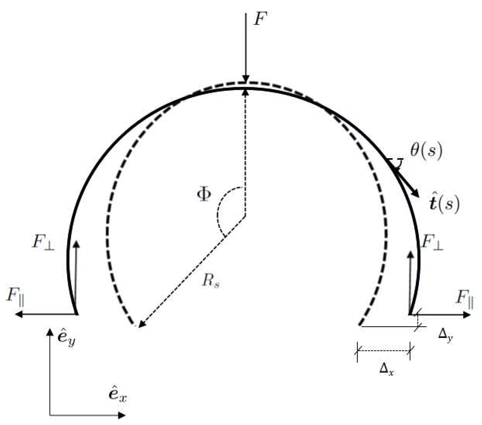
We consider an open cylindrical shell with radius of R s , thickness of t, length of L, and opening angle of Φ . It is pushed onto the surface of a rigid cylinder with a radius R c to form a simple cylindrical snap fit [23,24], as shown in Figure 10.
Taking into account the interactions between the topology, bending elasticity, and friction that are characterized by the initial opening angle Φ , mismatch ratio α = R c / R s , elasticity modulus E, and friction coefficient μ , the assembly process of the snap fit can be analytically formulated [23,24].
Based on the theoretical formulations of cylindrical snap fit by Yoshida and Wada [23], we have fitting expression of assembly force of 20o torus snap fit as follows
F A R s 2 B = 1.5 ( 2.8 0.1 Φ 0.2 Φ 2 ) f A ,
in which the assembly force ratio of the cylindrical snap fit is given by
f A = 2 α K x ( Φ ) S ( α , Φ , μ ) 1 ( sin Φ α ) 2 / 3 3 / 2 .
The fitting expression of disassembly force 20 torus snap fit is
F D R s 2 B = 1.7 ( 2.8 1.2 Φ + 0.325 Φ 2 ) f D ,
in which the disassembly force ratio of the cylindrical snap fit is given by
f D = 2 α K x ( Φ ) sin ( Φ / α ) α 1 sin Φ K x ( Φ ) / K x ( Φ ) g ( Φ / α , μ ) .
The elastic coefficients are defined as
K x ( Φ ) = Φ 2 ( 3 2 sin Φ Φ cos Φ ) cos Φ 1 ,
K x ( Φ ) = [ 1 2 + ( 1 Φ sin Φ 3 cos Φ 2 ) cos Φ ] 1 ,
where
g ( φ , μ ) = μ tan φ 1 + μ tan φ , S ( α , Φ , μ ) = tan [ ( α 1 sin Φ ) 1 / 3 ] K x ( Φ ) K x ( Φ ) g ( ( sin Φ α ) 1 / 3 , μ ) .
Figure 11 shows that the approximate analytical expressions in Eq.1 and Eq.3 are in good agreement with our finite element analysis.
Eq.1 and Eq.3 reveal that the torus snap fit has a greater carrying capacity than the cylindrical snap fit [23,24], since both coefficient functions " 1.5 ( 2.8 0.1 Φ 0.2 Φ 2 ) " and " 1.7 ( 2.8 0.1 Φ 0.2 Φ 2 ) " are greater than 1 in the domain of Φ ( π / 2 , π ) as shown in Figure 12, which confirms our prediction that given in the introduction: "we can foresee that the torus snap fit should have a greater assembly/disassembly force than the corresponding cylindrical snap fit."

5. Conclusions and perspectives

In this paper, we conducted a detailed study on thin-walled torus shell snap fit from two aspects: finite element simulation and experimental analysis. In order to facilitate the design prediction of snap fit’s assembly/disassembly force, we approximated the thin-walled torus snap fit as an equivalent cylindrical snap fit, and obtained an approximate analytical expression for the torus snap fit assembly/disassembly force through data fitting. It is worth noting that due to the Gaussian curvature of the thin-walled torus, which can be positive or negative, it has special geometric and mechanical properties. It was found that the assembly/disassembly force of the torus snap fit is larger than that of the equivalent cylindrical one. The mechanical performance of the thin-walled torus snap fit can be used to design linkages/connentions/joints and energy absorption mechanisms with special needs. Finally, to the best of the authors’ knowledge, this is the first detailed study of torus snap-fit mechanics in the context of the physics of thin structures. This study combines experiment, numerical simulation, and linear elasticity theory data fitting, reveals a quantitative design space for snap fits and illustrates how an exquisite combination of geometry, elasticity, and friction leads to an emergent mechanical asymmetry between the assembling and disassembling processes, which can be used for a range of mechanical designs with tunable functionalities.

Data Availability Statement

The data that support the findings of this study are available from the corresponding author upon reasonable request.

Acknowledgments

The authors wish to express their appreciation to the financial support from Xian University of Architecture and Technology (Project no: 002/2040221134).

Conflicts of Interest

The author declares that he has no known competing financial interests or personal relationships that could have appeared to influence the work reported in this paper.

References

  1. Rivera, J.; Hosseini, M.S.; Restrepo, D.; Murata, S.; Vasile, D.; Parkinson, D.Y.; et al. Toughening mechanisms of the elytra of the diabolical ironclad beetle. Nature 2020, 586, 543–548. [Google Scholar] [CrossRef] [PubMed]
  2. Wri, J.; Sun, B.H. Bioinspiration: Pull-Out Mechanical Properties of the Jigsaw Connection of Diabolical Ironclad Beetle’s Elytra. Acta Mechanica Solida Sinica 2023. [Google Scholar] [CrossRef]
  3. Sun, B.H. Closed-form solution of axisymmetric slender elastic toroidal shells. J. of Eng. Mech. 2010, 136, 1281–1288. [Google Scholar] [CrossRef]
  4. Sun, B.H. Toroidal Shells. (Nova Novinka, New York, 2012).
  5. Sun, B.H. Exact solution of Qian’s equation of slender toroidal shells (in Chinese). Mech. in Eng. 2018, 38, 567–569. (In Chinese) [Google Scholar]
  6. Sun, B.H. Small symmetrical deformation of thin torus with circular cross-cection. Thin-Walled Structures 2021, 163, 107680. [Google Scholar] [CrossRef]
  7. Sun, B.H. Geometry-induced rigidity in elastic torus from circular to oblique elliptic cross-section. Int.J. Non-linear Mech. 2021, 135, 103754. [Google Scholar] [CrossRef]
  8. Sun, B.H. Gol’denveizer’s problem of elastic torus. Thin-Walled Structures 2022, 171, 108718. [Google Scholar] [CrossRef]
  9. Sun, B.H. Nonlinear elastic deformation of Mindlin torus. Comm. in Nonlinear Sci. Num Sim. 2022, 114, 106698. [Google Scholar] [CrossRef]
  10. Song, G.K.; Sun, B.H. Nonlinear investigation of Gol’denveizer’s problem of a circular and elliptic elastic torus. Thin-Walled Structures 2022, 180, 109862. [Google Scholar] [CrossRef]
  11. Sun, B.H.; Song, G.K. The Mechanics Difference Between the Outer Torus and Inner Torus. J. Appl.Mech. 2023, 90, 071012–1. [Google Scholar] [CrossRef]
  12. W. Flügge, Stresses in Shells, Springer-Verlag Berlin, 1973.
  13. Gol’denveizer, A.L. Theory of Elastic thin Shells, Pergamon Press, New York, 1961.
  14. Audoly, B.; Pomeau, Y. Elasticity and Geometry (Oxford University Press, New York, 2010).
  15. Zingoni, A.; Enoma, N.; Govender, N. Equatorial bending of an elliptic toroidal shell. Thin-Walled Struct. 2015, 96, 286–294. [Google Scholar] [CrossRef]
  16. Jiammeepreecha, W.; Chucheepsakul, S. Nonlinear static analysis of an underwater elastic semi-toroidal shell. Thin-Walled Struct. 2017, 116, 12–18. [Google Scholar] [CrossRef]
  17. Enoma, N.; Zingoni, A. Analytical formulation and numerical modelling for multi-shell toroidal pressure vessels. Computers & Structures 2020, 232, 105811. [Google Scholar]
  18. Song, G.K.; Sun, B.H. Buckling of ellipsoid grid-shells made of smooth triaxial weaving with naturally in-plane curved ribbons. Thin-Walled Structures 2023, 191, 111060. [Google Scholar] [CrossRef]
  19. Bayer Corporation. Snap fit Joints for Plastics: A Design Guide (Polymer Division, Pittsburgh, PA, 1996).
  20. Bonenberger, P.R. The First Snap-Fit Handbook (3rd ed.), Hanser Publishers, Munich (2016).
  21. Dai, Y.F.; Sun, B.H.; Zhang, Y.; Li, X. Morphological transformation of arched ribbon driven by torsion. Thin-Walled Structures 2022, 170, 108511. [Google Scholar] [CrossRef]
  22. Xu, R.; He, Y.L.; Li, X.; Lu, M.H.; Chen, Y.F. Snap-fit mechanical metamaterials. Appl. Mat. Today. 2023, 30, 101714. [Google Scholar] [CrossRef]
  23. Yoshida, K.; Wada, H. Mechanics of a snap fit. Phys. Rev. Lett. 2020, 125, 194301. [Google Scholar] [CrossRef]
  24. Guo, X.L.; Sun, B.H. Assembly and Disassembly Mechanics of a Cylindrical Snap Fit. Preprints 2022, 2022010076. [Google Scholar] [CrossRef]
  25. Guo, X.L.; Sun, B.H. Assembly and disassembly mechanics of a spherical snap fit. Theor.Appl. Mech. Lett. 2023, 13, 100403. [Google Scholar] [CrossRef]
  26. Sun, B.H.; Guo, X.L. Clamping force of a multilayered cylindrical clamper with internal friction. Theor.Appl. Mech. Lett 2022, 12, 100355. [Google Scholar] [CrossRef]
  27. Moy, V.T.; Florin, E.L.; Gaub, H.E. Intermolecular forces and energies between ligands and receptors. Science 1994, 266, 257. [Google Scholar] [CrossRef]
  28. Suri, G.; Luscher, A.F. Structural abstraction in snap-fit analysis. J. Mech. Design. 2000, 122, 395. [Google Scholar] [CrossRef]
  29. Romano, M.; Friedman, D.A.; Shay, T.J. Laboratory experimentation of autonomous spacecraft approach and docking to a collaborative target. J. Spacecr Rockets 2007, 44, 164. [Google Scholar] [CrossRef]
  30. Benson, R.C. The Deformation of a thin incomplete, elastic ring in a frictional channel. J. Appl. Mech. 1981, 48, 895. [Google Scholar] [CrossRef]
  31. Benson, R.C. Stick/slip conditions for s thin, incomplete, elastic ring impinging on a frictional barrier. J. Appl. Mech. 1982, 49, 231. [Google Scholar] [CrossRef]
  32. He, X.Q.; Wang, C.M.; Lam, K.Y. Analytical bending solutions of elastics with one end held while the other end portion slides on a friction support. Arch. Appl. Mech. 1997, 67, 543. [Google Scholar] [CrossRef]
  33. Rafsanjani, A.; Akbarzadeh, A.; Pasini, D. Snapping mechanical metamaterils under tension. Adv. Mater. 2015, 27, 5931. [Google Scholar] [CrossRef] [PubMed]
  34. Sano, T.G.; Yamaguchi, T.; Wada, H. Slip morphology of elastic strips on frictional rigid substrates. Phys. Rev. Lett. 2017, 118, 178001. [Google Scholar] [CrossRef]
  35. Popova, E.; Popov, V. The research works of Coulomb and Amontons and generalized laws of friction. Friction 2015, 3, 183. [Google Scholar] [CrossRef]
  36. Wu, L.; Xi, X.; Li, B.; Zhou, J. Multi-Stable Mechanical Structural Materials. Adv. Eng. Mater. 2018, 20, 1700599. [Google Scholar] [CrossRef]
  37. Mose, B.R.; Son, I.-S.; Bae, J.-W.; Ann, H.-G.; Lee, C.Y.; Shin, D.-K. Modified analytical method to calculate the assembly and separation forces of cantilever hook-type snap-fit. J. Mech. Eng. Sci. 2019, 233, 5074. [Google Scholar] [CrossRef]
  38. Holmes, D.P. Elasticity and Stability of Shape-Shifting Structures. Curr. Opin. Colloid Interface Sci. 2019, 40, 118. [Google Scholar] [CrossRef]
  39. Sano, T.G.; Hohnadel, E.; Kawata, T.; Metivet, T. Florence Bertails-Descoubes, Randomly stacked open cylindrical shells as functional mechanical energy absorber. Comm. Mat. 2023, 4, 59. [Google Scholar] [CrossRef]
Figure 1. Region of positive (yellow) and negative (blue) Gaussian curvature K on torus of revolution.
Preprints 90014 g001
Figure 2. Different types of snap fits and their degrees of freedom as shown in red arrow. Cylindrical snap fit [23,24], Spherical snap fit [25].
Preprints 90014 g002
Figure 3. Full torus snap fit, 20o-torus snap fit with opening angel Φ , radius R s , torus rigid radius R c = 90 mm, friction coefficient μ = 0.21 , and radius ratio α = R c / R s . In this paper, for convenient the torus snap fit with θ is denoted as θ -torus snap fit.
Preprints 90014 g003
Figure 4. Finite element model. F A is assembly force, F D is disassembly force.
Preprints 90014 g004
Figure 5. Type I snap-fit with opening angle Φ = 2.3 rad (having small deflection before snap fit), assembly force ratio ( F R s 2 B ) and disassembly force ratio ( F R s 2 B ).
Preprints 90014 g005
Figure 6. Type II snap-fit with opening angle Φ = 2.8 rad (having large deflection M-shape before snap fit), assembly force ratio ( F R s 2 B ) and disassembly force ratio ( F R s 2 B ).
Preprints 90014 g006
Figure 7. Experimental set up: R s = 26.3 mm, R c = 30 mm, α = R c / R c = 1.14 , t = 1 mm, b = 8 mm , Φ = 2.2 rad.
Preprints 90014 g007
Figure 8. Torus snap fits as an equivalent cylindrical snap fit.
Preprints 90014 g008
Figure 9. FEM assembly force and disassembly force of Type I 20o torus snap fit and its corresponding equivalent cylindrical snap fit of type I.
Preprints 90014 g009
Figure 10. Schematic diagram of cylindrical snap fit [23,24].
Preprints 90014 g010
Figure 11. Type I 20 torus snap fit: Assembly and disassembly force vs. opening angle Φ .
Preprints 90014 g011
Figure 12. Coefficient functions " 1.5 ( 2.8 0.1 Φ 0.2 Φ 2 ) " and " 1.7 ( 2.8 0.1 Φ 0.2 Φ 2 ) " vs. 1.
Preprints 90014 g012
Table 1. Parameters of 20 -torus snap fit
Radius ratio Angle Thickness Opening angle
α θ ( ) t(mm) Φ (rad)
1.14 20 0.3 1.9
1.14 20 0.3 2.0
1.14 20 0.3 2.1
1.14 20 0.3 2.2
1.14 20 0.3 2.3
1.14 20 0.3 2.4
1.14 20 0.3 2.5
1.14 20 0.3 2.6
1.14 20 0.3 2.7
1.14 20 0.3 2.8
Disclaimer/Publisher’s Note: The statements, opinions and data contained in all publications are solely those of the individual author(s) and contributor(s) and not of MDPI and/or the editor(s). MDPI and/or the editor(s) disclaim responsibility for any injury to people or property resulting from any ideas, methods, instructions or products referred to in the content.
Copyright: This open access article is published under a Creative Commons CC BY 4.0 license, which permit the free download, distribution, and reuse, provided that the author and preprint are cited in any reuse.
Prerpints.org logo

Preprints.org is a free preprint server supported by MDPI in Basel, Switzerland.

Subscribe

© 2024 MDPI (Basel, Switzerland) unless otherwise stated