
Submitted:
09 November 2023
Posted:
09 November 2023
You are already at the latest version
Abstract
This paper presents the design and experimental results of a long cavity length Nd: YAG laser with large stable zone for water jet guided laser (WJGL) applications. The design is based on the light transmission matrix and resonator stability conditions, aiming to achieve a large stable zone and a short cut-off thermal focal length (CTFL). A folded concave resonator is researched to enhance the cavity length, and the influence of the tun-able cavity arm length on the oscillating beam in the resonator and in the YAG crystal is theoretically studied. Moreover, the effects of the output mirror curvature and the cavity arm length on the range of the stable area and the cut-off thermal focal length are also investigated. Experimental results show that a stable green laser output is obtained after second harmonic generation (SHG), with a pulse width ranging from 43ns to 143ns within the laser operating frequency range of 5-20kHz. At an operation frequency of 10kHz, the output power is 21.33W, and the instability of the output power within 400 minutes is 0.88%. The laser source achieves a maximum power of 25.7W at 20kHz, and the maximum single pulse energy reaches 2.7mJ at 6kHz. Finally, this is used as the laser source to couple with a water jet with a diameter of 100 microns, achieving a lossless water conductivity transmission over 60mm length with a peak power density of 0.742GW/cm2. These results demonstrate the suitability of the designed laser source for WJGL technology research.
Keywords:
high stable
; stable zone
; water jet guided laser
; green laser
; high repetition frequency
1. Introduction
Water jet guided laser (WJGL) is a composite processing technology that has attracted the attention of scholars due to its features of minimal thermal damage , high precision, and powerful processing energy [1,2,3]. WJGL technology opens up new applications and possibilities for various fields, including precision machining, medical surgery, and aerospace engineering. In the field of precision machining, WJGL technology can offer precise and efficient cutting capabilities. The combination of a high-power laser beam and a micro water jet enables the cutting with the advantage of high precision and minimal heat-affected zones. This technology has the potential to revolutionize industries such as jewelry [4] automotive [5], electronics [6], and aerospace industry [7,8], where precision cutting is crucial for manufacturing components. For example, in the aerospace industry, WJGL technology will be utilized for various purposes such as composite cutting [9,10] and turbine blades shaping [11].
In order to address the process challenges of large depth and quality consistency in water guided machining, it is necessary to simultaneously address the issues of stability, high power or high energy of laser. The WJGL technology was invented by Synova Company [12]. At present, laser light sources used for water guiding applications internationally generally have the following characteristics: (1) green light band, (2) laser operating frequency ranges from several thousand hertz to several tens of kilohertz, (3) the output pulse width is in the order of hundreds of nanoseconds or microseconds.. For example, Levent Subasi [13] et al. used a 25W, 10kHz, 200ns, 532nm laser to introduce a jet with a diameter of 150 microns for drilling chromium nickel iron alloy. Zhang W.W. [14] et al. conducted experimental resea on carbon fiber composite cutting using a WJGL of 30W, 40kHz, 532nm and a diameter of 100 microns. Qiao H.C. [15] et al. used 25W, 300ns, 20-120kHz, 532nm laser coupling with a jet of 60 microns diameter for research on cutting single-crystal silicon. Yang L.J. [16]et al. carried out processing research on ceramic matrix composite through a 25W, 20ns, 30kHz, 532nm laser coupling with a jet of a diamter of 100microns.
Considering that water guide applications require efficient coupling with micron scale water jets, there is a high demand for beam quality. Therefore, how to balance the output of high-power and high-beam-quality, and ensure that the stability of the resonator does not decrease, is the focus of research on water guided laser light sources. Nd: YAG crystals have a high-efficiency four level structure, but thermal effects limit the further improvement of the average power or energy of Nd: YAG lasers, and also affect the stability and beam quality. The control of the stable region state of the resonator mainly lies in researching the thermal effect of laser crystals [17,18,19]. Sundar R. [20]et al. reduced the thermal lens effect and improved the output beam quality factor by rotating the pump LDs angle. Wang K. [21] et al. reported the research results of thermal induced wavefront aberrations in liquid-cooled Nd: YAG thin plate lasers, achieving mutual compensation for wavefront differences. Wang S.Y. [22,23] et al. develop a quasi steady state thermal model to analyze transient thermal effects in Nd :YAG laser crystal under quasi-continuous laser-diode (LD) end pumping.
Here, based on the stable cavity design method, this paper reports a stable concave oscillating cavity by tuning the cavity length and adjusting mirror curvature to control the beam quality(M2~1.34). The effects of cavity arm length and cavity mirror curvature on the oscillating beam , stable region range, and cutoff thermal focal length were studied. A highly stable green laser with hundreds of nanosecond pulse widths was obtained at operating frequency range of 5-20kHz, the stability is 0.88% within 400 minutes. The maximum power and pulse energy was 25.7W, 2.7mJ respectively. The comprehensive indicators meet the requirements for light sources in the research of WJGL technology. Coupled with a micro water jet of 100μm diameter, several tens of millimeters lossless WJGL transmission is achieved of peak power density up to 0.742GW/cm2.
2. Experimental Setup
The design of the stable spherical resonator is shown in Figure 1. The cavity mirrors are all concave mirrors, consisting of a reflection mirror M1, M2, M3, and an output mirror M4, with curvatures denoted as R1, R2, R3, and R4, respectively. Adopting semiconductor side pumping, and the laser gain crystal is Nd: YAG, with a size of Φ2 * 60mm and a doping concentration of 0.5at%, placed near the center of the cavity. The distance between cavity mirrors M1 and M2 is called the cavity arm L1. The distance between cavity mirror M2 and laser crystal is denoted as L2, the distance between laser crystal and cavity mirror M3 is denoted as L3, the distance between cavity mirror M3 and acoustooptic crystal is denoted as L4, the distance between acoustooptic crystal and doubling crystal is denoted as L5, and the distance between doubling crystal and cavity mirror M4 is denoted as L6. The cavity mirror M1 is fixed on a precision translation platform, model of GCD-302001M, with a repeated positioning accuracy of 0.05mm, and the movement direction is consistent with the direction of cavity arm L1. Adopting intracavity frequency doubling, the frequency doubling crystal is LBO, placed near the output mirror M4, with a size of 3mm x 3mm x 15mm, of the θ angle is 90 °and the φ angle is 10.8 °. One side near the acousto-optic crystal is coated with 1064nm anti reflection film(HR<0.5%@1064nm) and 532nm high reflection film(HR>99.5%@532nm), while the other side is coated with anti reflection film(HR<0.5%@1064nm+532nm).
3. Theory
Due to the thermal lens effect, YAG crystals can be treated as a thick lens [24,25], the thermal lens focal length noted as fth. For the resonanter structure shown in Figure 1, according to the intracavity light transmission matrix, with the mirror M1 as the starting point, the paraxial round-trip matrix M of the base film Gaussian beam to and fro in the cavity is:
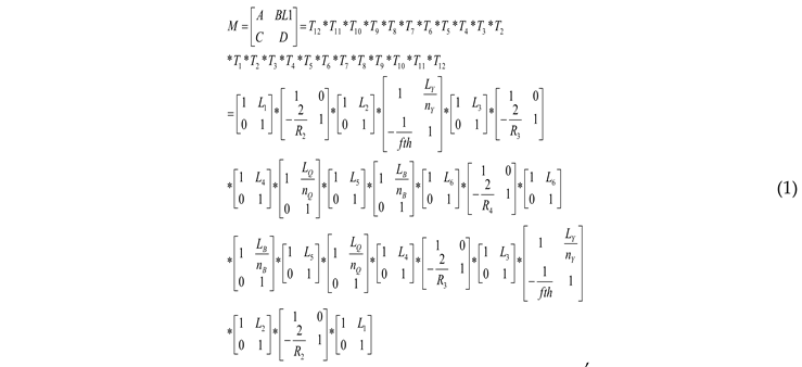
Here,in equation (1): LY is the length of Nd: YAG crystal, nY is the refractive index of Nd: YAG, LQ is the length of the acoustooptic crystal, nQ is the refractive index of the acoustooptic crystal, LB is the length of the LBO crystal, and nB is the refractive index of LBO crystal.
The q parameter of intracavity self reproducing Gaussian beam propagation is:

In equation (2), rM is the curvature radius of the wave surface on the reference cavity mirror surface, and ωM is the size of the light spot on the reference cavity mirror surface. With the mirror M1 as the reference plane, after the transmission distance L ', the relationship between the propagation q parameter of the base film Gaussian beam on this plane (and the beam waist q0 parameter is as follows:

Substituting formula (2) into (3) and combining it with the self reproduction condition of the intracavity beam, the q0 parameter formula at the waist of the beam can be obtained as follows:

Due to the fact that the wave surface at the waist of the intracavity transmission beam is a plane, i.e. the real part in formula (4) should be 0. Formula (4) can be simplified and the radius of the intracavity waist spot as:

Based on the size of the light spot on the mirror surface of the reference cavity or beam waist in the resonator the size of the oscillating light spot at any position in the resonator can be solved using formula (3).
In the simulation calculation next, the curvature of R2 and R3 are both set as 500mm, and the lengths from L4 to L6 are 195mm, 5mm, and 5mm respectively. The length of the acoustooptic crystal is 20mm.
4. Simulation Calculations and Experimental Results
4.1. Influence of cavity length tuning
According to the above formulas, simulate and calculate the oscillating mode in the resonant cavity, and the results are shown in Figure 2. Figure 2a–d show the distribution of the oscillation beam radius at various locations in the resonator, corresponding to the cavity arm lengths L1 of 400mm, 500mm, 600mm, and 700mm, respectively. The vertical axis represents the oscillation beam radius, and the horizontal axis represents the positions with cavity mirror M1 as the origin. Corresponding to Figure 2a–d, the physical total length of resonant cavity is 932mm, 1032mm, 1132mm, and 1232mm, respectively. It can be seen that, firstly, as the length of the cavity arm increases from 400mm to 700mm, even if the cavity length changes by 300mm, the oscillation of the cavity beam can still be maintained stable without considering thermal lens. The radius of the oscillation beam waist spot in the cavity is 0.2392mm, 0.2723mm, 0.2458mm, and 0.1960mm, respectively. And as the cavity arm L1 increases, the waist position gradually moves towards the output mirror M4.
According to the simulation calculation results in Figure 3, the laser crystal is placed at the center of mirror M2 and mirror M3, with lengths of 116mm for both L2 and L3. Analyze the oscillation spot situation in laser crystals with different lengths of cavity arm L1 , and the results are shown in Figure 3. Figure 3a shows that when the length of the Nd: YAG crystal is 60mm, the radius of the oscillating spot inside the crystal increases from 0.2142mm to 0.4110mm with the increase of L1. Reducing the size means that the volume of the intracavity mode is small, which affects the power output. Figure 3b shows the difference value between the maximum and minimum size of the oscillating spot in the Nd: YAG crystal. As L1 increasing, the difference value decreases firstly and then increases. The overall difference value is less than 70μm. When L1 is 500mm, the minimum difference value is only 6μm. The amplitude of change is approximately 3.1% of the size of the central oscillation spot.
4.2. Analysis of the impact on the stable aera
Change the curvature R4 of cavity mirror M4 and perform stable zone calculations for different curvatures(R4=300mm, 600mm, 2000mm, and 6000mm). The corresponding results are shown in Figure 4a–d. The red area represents the stable zone range, the pink area represents the unstable zone range, the blue line represents the stable zone boundary, and the ordinate represents the thermal focal length. The thermal focal length at the boundary of the stable zone is the cut-off thermal focal length(CTFL). As a symbol of the stable state of the laser, the cutoff thermal focal length is the minimum thermal focal length that the laser meets in the stable zone state.
It is evident that the stable zone ranges in Figure 4a,b are larger than those in Figure 4c,d. In Figure 4c,d, when L1 is less than 500mm, the cut-off thermal focal length is nearly infinite,much larger than 1200mm , which indicating that the resonant cavity is always in an unstable state. IIt can be seen from comparison that the curvature of the cavity mirror M4 should not be too large.
Compare the cutoff thermal focal length under different cavity arms L1 in two modes(R4=300mm,600mm).The results are shown in Figure 5, with the ordinate being CTFL. From Figure 5, it can be intuitively seen that when R4 is equal to 600mm, as L1 changes from 400-700mm, the length of CTFL is always shorter than the other curve. When R4 is 600mm and L1 varies within 400-600mm, the cutoff thermal focal length is 55mm, 129mm, and 287mm corresponding , which reduces significantly compared to L1 at 700mm.
Shown in Figure 6, as R4 of 600mm, the size state of the beam waist spot under different thermal focal lengths within the stable zone is studied. the horizontal axis represents the positions, The vertical axis represents , Figure 3a intuitively displays the relationship between the length of thermal focal length(fth), beam waist radius in resonant cavity, and cavity arm L1. As shown in Figure 6b, the waist beam spot size in the cavity shows a trend of firstly increasing and then decreasing consistently under the fth of 300mm, 500mm, 700mm, and 900mm. Under the same cavity arm L1 length, as the fth increases, the beam waist spot in cavity become larger. When L1 as between 400-500mm, the variation in the radius of the beam waist in resonant cavity is relatively minimal, basically at a high level value. It mean that the stability of the output power will not be significantly fluctuated due to the changes in thermal focal length.
4.3. Experimental results
Install a flat concave mirror with a curvature of 600mm on a precision motion table as the cavity mirror M1. Set the curvature R4 of the cavity mirror M4 is 600mm through the simulation calculation above .Through the control of precise motion table , the length of cavity arm L1 is tuned as 500mm, and the total physical length of the resonant cavity is 1032mm. After LBO crystal phase matching frequency doubling, a green pulse light with an average power of 21.33W is obtained at operating frequency of 10kHz.. The average output laser power curve is shown in Figure 7. Figure 7a shows the curve variation of output green light power with pump current., and Figure 7b shows the power stability monitoring result. As shown in Figure 7a, when the maximum pump current is reached, the average output power is 21.33W. Conduct stability testing at maximum power, as shown in Figure 7b, and set the display cycle duration of the recording screen to 60 minutes. Within 400 minutes, the maximum output power is 22.22 W, the minimum output power is 20.60 W, the average output power is 21.33 W, and the root mean square value difference is 188.6 mW. The calculated root mean square (RMS) instability of the output power is 0.88%. To some extent, it has reached industrial grade stability performance. After transmitting a certain distance, the 3D shapes of the beam is observed on a light spot analyzer, as shown in the small image in the upper left corner of Figure 7a, with a roundness of about 92%. The model of the beam analyzer is Ophir Spiricon's SP620U.
The maximum output power and single pulse energy curves at different frequencies are shown in Figure 8. The laser can maintain a stable working state within the operating frequency range of 5-20kHz, and the maximum output power increases with the increasing of the operating frequency. The maximum output power at 20kHz is 25.7W. The growth rate of output power is slower than the increase rate of pulse operating frequency. The single pulse energy reaches its maximum at approximately 6kHz, of 2.72mJ.Within the range of 5-10kHz, the single pulse energy remains above 2.0mJ.
The laser pulse width at different frequencies is shown in Figure 9. The pulse pictures at each operating frequency were collected using a oscilloscope(RIGOL company, model:MSO5204), and the results are shown in Figure 9. It can be seen that as the frequency increases, the pulse width increases congrouously. The average pulse width is 46.0ns , 60.375ns , 82.875ns , 116.12ns and 143.62ns,corresponding the frequency of 5kHz, 7kHz, 10kHz,15kHZ and 20kHz. Fit according to an exponential curve, with a fitting function of:
Here, A1 is -328.71092, t1 is 35.5073, and y0 is 331.0121. The fitting curve is shown by the green dashed line in Figure 9.
After through the reflector, wave plate, polarization crystal, and attenuation plates group, a beam quality analyzer is used to collect the morphology of the beam at maximum power with different frequencies,the results are shown in Figure 10. The vertical axis in Figure 10 represents the ratio of the collected spot size in the y direction (short axis) to the size in the x direction (long axis). Considering that the parallelism of the optical axis of the added power attenuation optical module is not completely consistent, this to some extent affects the circularity of the light spot, which slightly decreases compared to the circularity of the three-dimensional light spot in Figure 7a. The long cavity of 1032mm is contribute to control beam quality by mode selection. Measure the beam diameters at different distances from a lens at the maximum output power of 10kHz. By calculating, the result of the beam quality M2 was approximately 1.34.
Finally, combined with the self-developed structure, the output pulse laser is tightly focused and coupled into the micro water jet of 100μm diameter, as shown in Figure 11. Littler beam quality M2 factor is beneficial for obtaining smaller focused light spots after focusing.The small image in the upper right corner of Figure 11 shows the jet nozzle, and the small green light spot in the center of the nozzle is the coupled focused light spot. The plasma explosion threshold of laser in water is lower, and the water quality will further affect the explosion threshold. Plasma explosion will affect the total reflection, causing laser scattering in the water jet. In order to achieve lossless transmission, it is required that the laser operating frequency should not be too low and the single pulse energy should not be too large. From the Figure 11, it can be seen that the laser undergoes total reflection in the water jet below the nozzle without any flash points of plasma explosion. After a certain distance of total reflection transmission, scattering phenomenon occurs. The total reflection transmission area has a length reaching 60mm, and after exceeding the 65mm area, scattering gradually occurs. This indicates that the high repetition rate of 5-20kHz and high power green laser designed in this article is suitable for applicating in WJGL field, especially suitable for deep processing of materials. As the laser frequency increases, the peak power density of the WJGL gradually decreases. The maximum peak power density is 0.742GW/cm2.
5. Discussion
Concave mirrors have a converging effect on the beam. Therefore, using a four-mirror concave cavity can obtain three converging oscillating beam in the resonant cavity. Changing the curvature of the cavity mirror can dajust the size of the oscillating beam. From Figure 2a–d, it is found that the resonant cavity designed has an important characteristic. No matter how the cavity length changes, there is always a section of oscillating beam between the cavity mirrors M2 and M3, which is close to parallel beam. By utilizing this characteristic, placing the laser crystal Nd: YAG at this position in the cavity can effectively balance the temperature field distribution inside the laser crystal. The result is that , it can be seen from Figure 3b the minimum difference in the size of the oscillating spot within the laser crystal is only 6 μm. And the variation of L1 within the range of 400mm to 600mm has little impact on the mode of oscillation spot in the resonant cavity, including the waist size and the difference size of oscillation spot in the crystal.
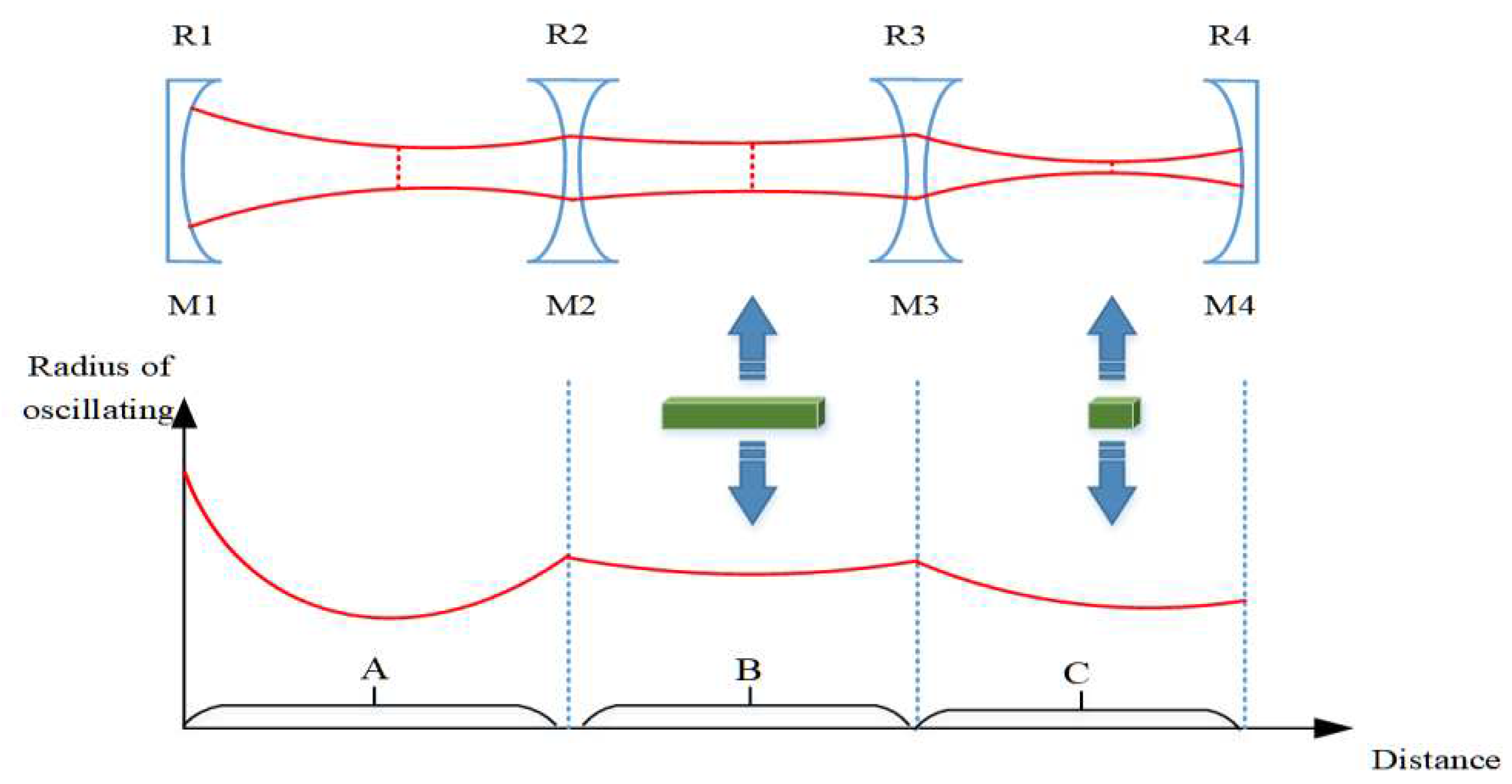
As shown in Figure 1, a fold-able resonant cavity designed with a set of concave mirrors can be expanded into a linear shape. The equivalent resonant cavity is shown in Figure 12. The curvature on both sides of cavity mirror M2 is equal, similarly, the curvature on both sides of cavity mirror M3 is also equal. A concave mirror has the ability to concentrate light beams. Therefore, by using a four mirror concave cavity, three converging oscillating light spots can be obtained in the resonant cavity. The resonant cavity is divided into three regions, labeled A, B, and C, where these three converging oscillating light spots are located respectively. By referring to telescope theory, the size of the oscillating beam can be accurately changed by changing the curvature or spacing of the cavity mirror.
Firstly, the cavity mirrors M1 and M2 form a con-focal cavity. The curvatures R1 and R2 can be adjusted to control the size of the converging beam in region A. The length L1 of the cavity arm is adjusted to ensure that the oscillating beam in region A converges at the focal point of the left surface of the cavity mirror M2. Then, it is important to ensure that the oscillating beam in region B gradually becomes parallel light. This configuration is suitable for placing large length laser gain crystals. This characteristic is illustrated in Figure 2a–d: regardless of changes in the cavity length, there is always an oscillating beam between the cavity mirrors M2 and M3 that closely resembles a parallel beam. By utilizing this characteristic, the laser crystal Nd: YAG can be effectively positioned at this location in the cavity to achieve a balanced temperature field distribution inside the laser crystal. Furthermore, Figure 3b shows that the oscillating spot size difference within the laser crystal is only 6 μm. The variation of L1 between 400mm to 600mm has minimal impact on the overall oscillation mode of the resonant cavity, consistently maintaining a three-stage convergence regions labeled. The parallel beams formed by region B converge again after passing through M3, creating a common focus within region C. The size of the oscillating spot can be quickly modified by adjusting the curvature of either the front or rear mirrors. For example, changing the curvature of the rear cavity mirror M4 can affect the beam in region C. According to the principles of telescopes, there is a specific numerical relationship between the beam focus in region C and the beam focus in region A, which naturally alters the size of the oscillating beam in region A. n this study, the position of the rear cavity mirror M4 is fixed, which is advantageous for use as an output mirror. Therefore, region C is designated as the placement area for Q-switching crystals and frequency doubling crystals.
As the laser power increases, the thermal focal length within the crystal becomes shorter. The CTFL symbolizes the laser's stable state and represents the minimum thermal focal length achievable in this state. To maintain the stable state of the resonant cavity and minimize the influence of the thermal lens effect, it is necessary to minimize the CTFL as much as possible. Considering all factors and referring to Figure 5 and Figure 6, the curvature R4 of the cavity mirror M4 is selected as 600mm. L1 is determined to be 500mm. Additionally, the CFTL, which meets the critical stability zone conditions, is as low as 129mm. This exceeds the limit of the thermal focal length that laser crystals can reach when operating at high power, ensuring long-term stability of the laser.
6. Conclusions
In summary, based on long resonant cavity mode selection and stable zone control, this article achieves high stability and high-power pulsed laser which can be used for long distance lossless transmission of WJGL. It provides strong technical support for the deep, efficient and high-quality processing of materials. Compared with the current process parameters of water guided laser processing, this high repetition rate Nd: YAG green laser with a large stable range and high stability is a very suitable laser source.
In this paper, we designed a folded concave oscillating cavity, which has the characteristic of the tunable length of the cavity arm in the stable zone state. Using the ray transfer matrix method, the influence of the length of the tuning cavity arm L1 on the oscillating beam in the cavity and crystal is analyzed. Furthermore, the effects of output mirror curvature and cavity arm L1 on the scope of the stable zone and the CTFL are studied, taking into account the thermal focal effect. Research resluts have shown that:
When R4 is 600mm, the stable zone scope is sufficiently large. Meanwhile, when L1 varies between 400-600mm, the change amplitude of the size of beam waist in resonator and the CTFL both are relatively low , which can effectively suppress the influence of thermal focal effect to stabel the output power.
According to the design, the total physical length of the resonant cavity is 1032mm. 21.33W of average power and 0.88%(RMS) of unstable value is obtained at a working frequency of 10kHz within 400 minutes. Changing the pulse frequency to 5-20kHz the resonantor can still maintain stable operation, with a maximum output power of 25.7W and a maximum single pulse energy of 2.7mJ.
After experimental verification, the laser designed in this paper is perfectly coupled with a water jet of 100 microns diameter, achieving lossless transmission over 60mm for water jet guidied laser.
Author Contributions
Conceptualization, J.W. and W.Z.; investigation, J.W..; methodology, J.W. and W.Z.; validation, J.W. and W.Z.; funding acquisition, J.W.; supervision, W.Z.; writing—original draft, J.W.; writing—review and editing, J.W. and W.Z; funding acquisition, J.W. and W.Z. All authors have read and agreed to the published version of the manuscript.
Funding
Excellent projects in Zhejiang Province (Grant No. 2020C01036), Director's Fund of Ningbo Institute of Materials Technology and Engineering, Chinese Academy of Sciences (Grant No.2021SZKY0309), the National Natural Science Foundation of China under (Grant No.51805525) and Natural Science Foundation of Ningbo City (Grant No.2021J215).
Data Availability Statement
The data that support the findings of this study are available from the corresponding author upon reasonable request.
Conflicts of Interest
The authors declare no conflict of interest.
References
- Zhang, Y.N; Qiao, H.C; Zhao, J.B.; Cao, Z.H. Research on the Mechanism of Micro-Water Jet-Guided Laser Precision Drilling in Metal Sheet. Micromachines, 2021, 12 , 343. [CrossRef]
- Wang, S.W.; Ding, Y.; Li Y.; Ge, C.C.; Xie, W.D; Huo, H.D.; Yang, L.J.; Zhang, Wei; Lu, Y.Q. Investigations on the water-jet guided laser scribing of thermal barrier coated IC21 nickel-based superalloy. Opt. Laser Technol.,2021,113,1-15.
- Cao, Z.H; Qiao, H.C.; Zhang, Y.N.; Chen, Y.L.; Zhao, J.B. Study on reducing burrs of super alloy through structures in water jet guided laser ablation. J. Mater Process Tech., 2022, 77, 809-818. [CrossRef]
- Wei, Q.; Zhang, X.; Lin, F.; Wang, H.X. Fabrication of Micron Scale Three-Dimensional Single Crystal Diamond Channel: by Micro-Jet Water-Assist Laser.Materials, 2021, 14, 3006. [CrossRef]
- Zhao, C.; Zhao, Y.G.; Zhao, D.D.; Meng, S.; Zhang, G.G; Cao, C.; Zhang, H.Y.; Meng, J.B. Annular gas-assisted water-jet guided laser manufacturing groove structure of Inconel 718 alloy. Int. J. Adv. Manuf. Tech.,2023, 128, 9-10. [CrossRef]
- Marimuthu, S.; Dunleavey, J.; Liu, Y.; Smith, B.; Kiely, A.; Antar, M. Water-jet guided laser drilling of SiC reinforced aluminium metal matrix composites. J. Compos. Mater.,2019, 53, 26-27. [CrossRef]
- Subasi, L.; Gokler, M.I.; Yaman, U. A comprehensive study on water jet guided laser micro hole drilling of an aerospace alloy.Opt. Laser Technol.,2023,164, 109514. [CrossRef]
- Marimuthu, S.; Smith, B. Water-jet guided laser drilling of thermal barrier coated aerospace alloy. TInt. J. Adv. Manuf. Tech.,2021, 113, 1-15. [CrossRef]
- Zhang, Y.; Qiao, H.; Zhao, J.B; Cao, Z.H; Yu, Y.F. Numerical simulation of water jet–guided laser micromachining of CFRP. Mater. Today Commun. ,2020, 25, 101456. [CrossRef]
- Sun, D.; Han, F.; Ying W. Numerical simulation of water jet–guided laser cutting of carbon fiber–reinforced plastics. P. I. Mech. Eng B-J. Eng.,2019, 233, 2023-2032. [CrossRef]
- Huang, Y.X.; Liang, E.; Zhang, G.H.; Zhou, L.; Huang, P.; Jiao, H.; Zhou, J.; Zhong, Z.X.; Shi, T.L.; Long, Y.H. Research on laser beams focusing and coupling technology of water jet guided laser with high adjustment tolerance. Opt. Commun.,2022, 508, 127677. [CrossRef]
- Richerzhagen B. Finite element ray tracing: a new method for ray tracing in gradient-index media. Appl. optics, 1996, 35, 6186-6189. [CrossRef]
- Levent S.; Mustafa I.; Gokler, U. Y. Multi objective optimization of water jet guided laser micro drilling on Inconel 718 using Taguchi Method. Procedia CIRP, 2020, 94 , 505-510. [CrossRef]
- Wu, Y.W.; Zhang, G.Y.; Wang, J.X.; Chao, Y.; Zhang, W.W. The cutting process and damage mechanism of large thickness CFRP based on water jet guided laser processing. Opt. Laser Technol.,2021, 141 ,107140. [CrossRef]
- Qiao, H.C; Cao, Z.H.; Cui, J.F; Zhao, J.B. Experimental study on water jet guided laser micro-machining of mono-crystalline silicon. Opt. Laser Technol.,2021, 140 , 107057. [CrossRef]
- Cheng, B.; Ding, Y.; Li, Y.; Li J.Y.; Xu, J.J.; Li, Q.; Yang, L.J. Coaxial helical gas assisted laser water jet machining of SiC/SiC ceramic matrix composites. J. Mater Process Tech., 2021, 293, 167. [CrossRef]
- Al Hosiny, N. M.;El Maaref, A. A.;El Agmy, R. M. Mitigation of Thermal Effects in End Pumping of Nd:YAG and Composite YAG/Nd:YAG Laser Crystals, Modelling and Experiments. Tech. Phys. ,2022, 66, 1341-1347. [CrossRef]
- Li, J.; Zhang, H.; Wang, L.; Liu, X. Thermal Effect Suppression of Nd:YAG Laser Using Water Cooling Technique. J. Laser Micro Nanoen., 2018,13, 38-42.
- Kim, D.L.; Ok, C.M.; Jung B.H.; Kim B.T. Optimization of pumping conditions with consideration of the thermal effects at ceramic Nd:YAG laser. Optik, 2019, 181 ,1085-1090. [CrossRef]
- Sundar, R.; Hedaoo, P.; Ranganathan, K.; Soni, J.K.; Bindra, K.S.; Oak S.M. Modular pump geometry for diode side-pumped high-power Nd:YAG rod laser. Appl. Opics., 2015, 54 ,009855. [CrossRef]
- Wang, K; Wang, R; Yi, H.Y.; Wang, W.Z.; Deng, K.R.; Jiang, M.H.; Yadav, N.P.; Li, Lei; Yi, J.Y. Thermal analysis of side-pumped direct-liquid-cooled Nd: YAG thin-disk lasers. Optik, 2022, 261, 169221. [CrossRef]
- Shang, P.J.; Bai, L.; Wang, S.Y.. Study of Transient Thermal Effects in a Nd :YAG Laser Under Quasi-Continuous Laser-Diode End Pumping. J. Russ. Laser Res. ,2023, 44, 323-332. [CrossRef]
- Shang, P.J; Wu, M.Y.; Wang, S.Y.; Cai, D.F.g;Li, B.B. Thermal lens Q-switched 1064 nm Nd:YAG laser. Opt. Commun., 2022, 507, 127676. [CrossRef]
- Kim, D. L.; Kim, B.T. Characteristics of laser beam produced by thermal lensing effect compensation in a fiber-coupled laser-diode pumped Nd:YAG ceramic laser. J. Korean Phys. Soc., 2010 , 57, 227-232. [CrossRef]
- Wen, Y. ; Wu, C.T.;Niu, C.; Zhang H.L. Wang, C. ; Jin, G.Y. Study on thermal effect of mid-infrared single-ended bonded Tm LuAG laser crystals. Infrared Phys. Tech., 2020, 108, 103356. [CrossRef]
Figure 1.
Tun-able cavity length resonator device diagram.
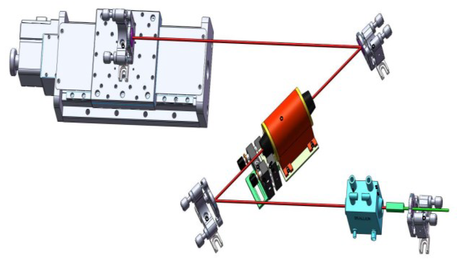
Figure 2.
Simulation of intracavity oscillating spot with different length of cavity arm: a) L1=400mm; (b) L1=500mm; (c) L1=600mm; (d) L1=700mm.
Figure 2.
Simulation of intracavity oscillating spot with different length of cavity arm: a) L1=400mm; (b) L1=500mm; (c) L1=600mm; (d) L1=700mm.
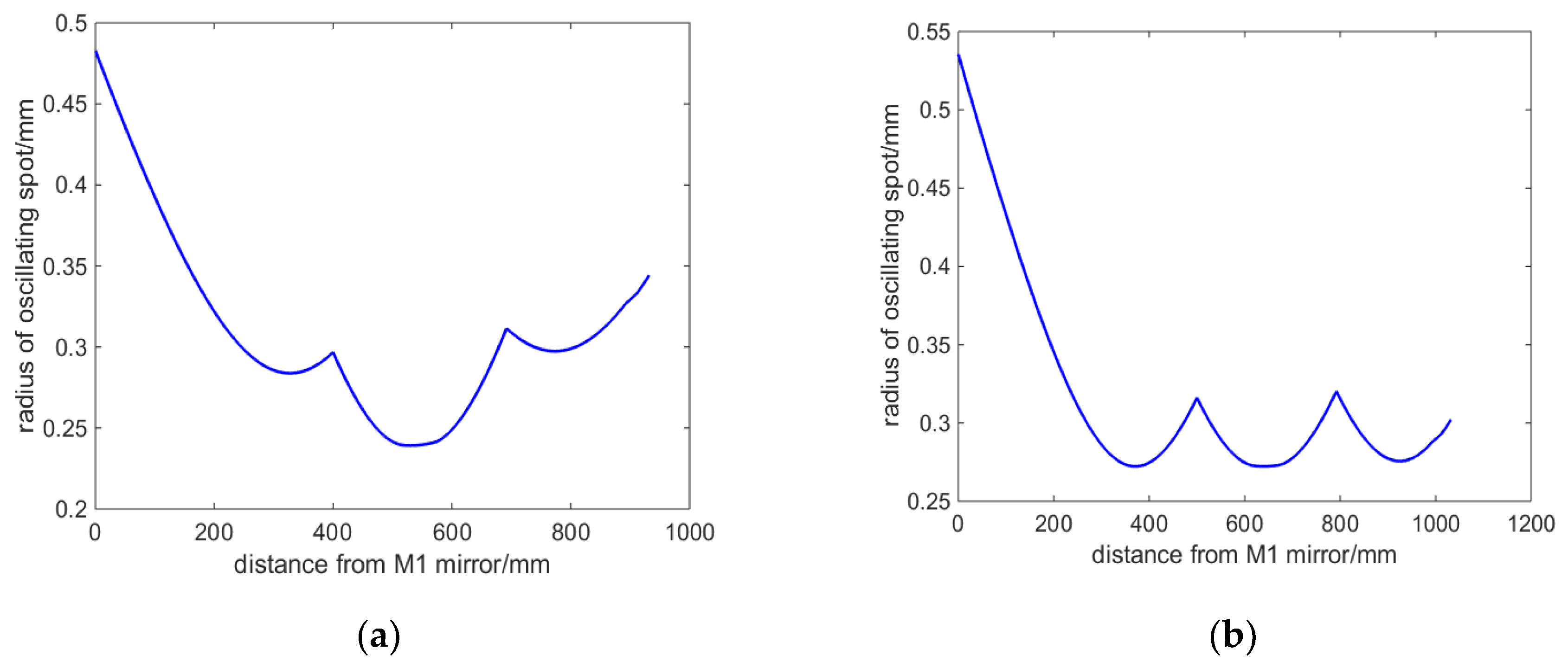
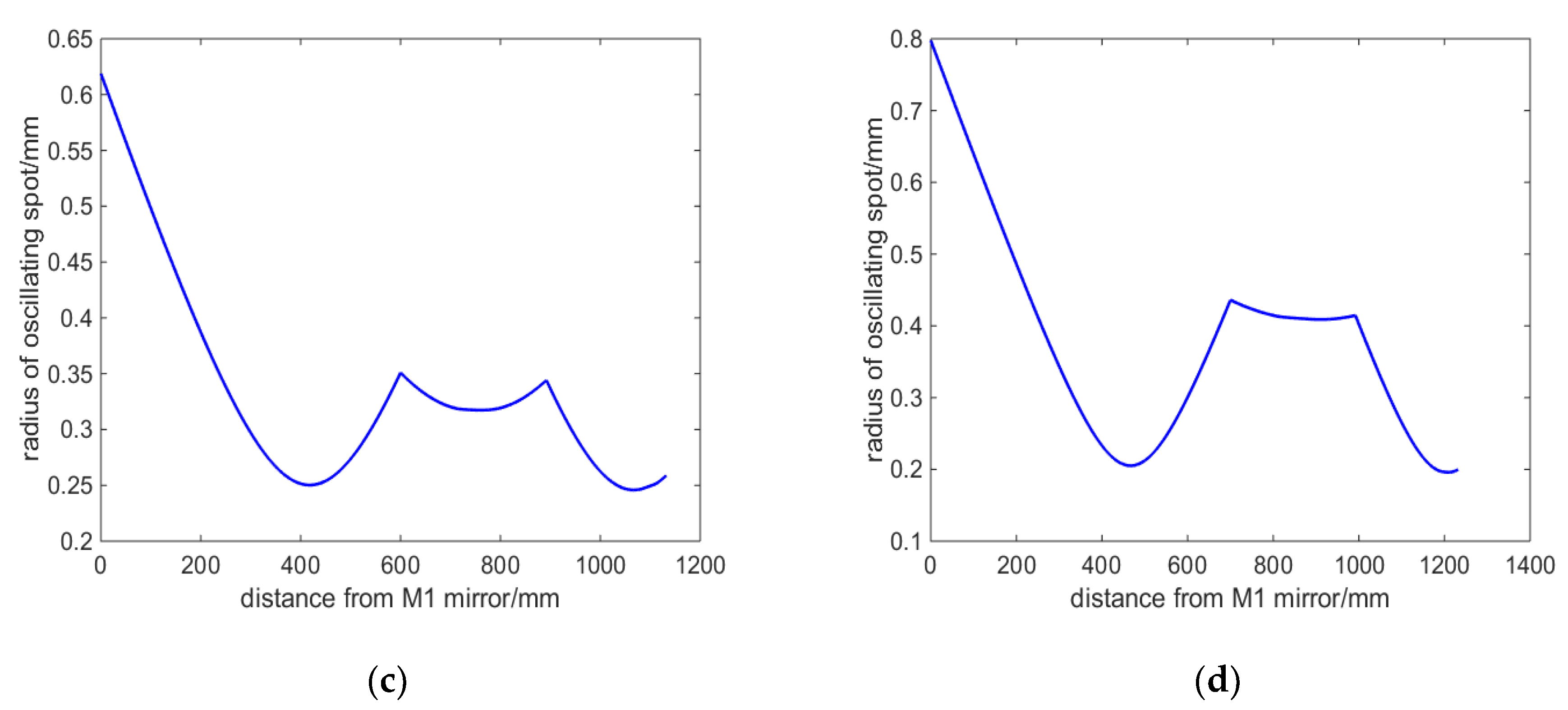
Figure 3.
Oscillating Spot in Laser Crystals with Different Length L1 of Cavity Arms: (a) oscillating spot size at center of laser crystal; (b) difference value of oscillating light spot size in laser crystals.
Figure 3.
Oscillating Spot in Laser Crystals with Different Length L1 of Cavity Arms: (a) oscillating spot size at center of laser crystal; (b) difference value of oscillating light spot size in laser crystals.
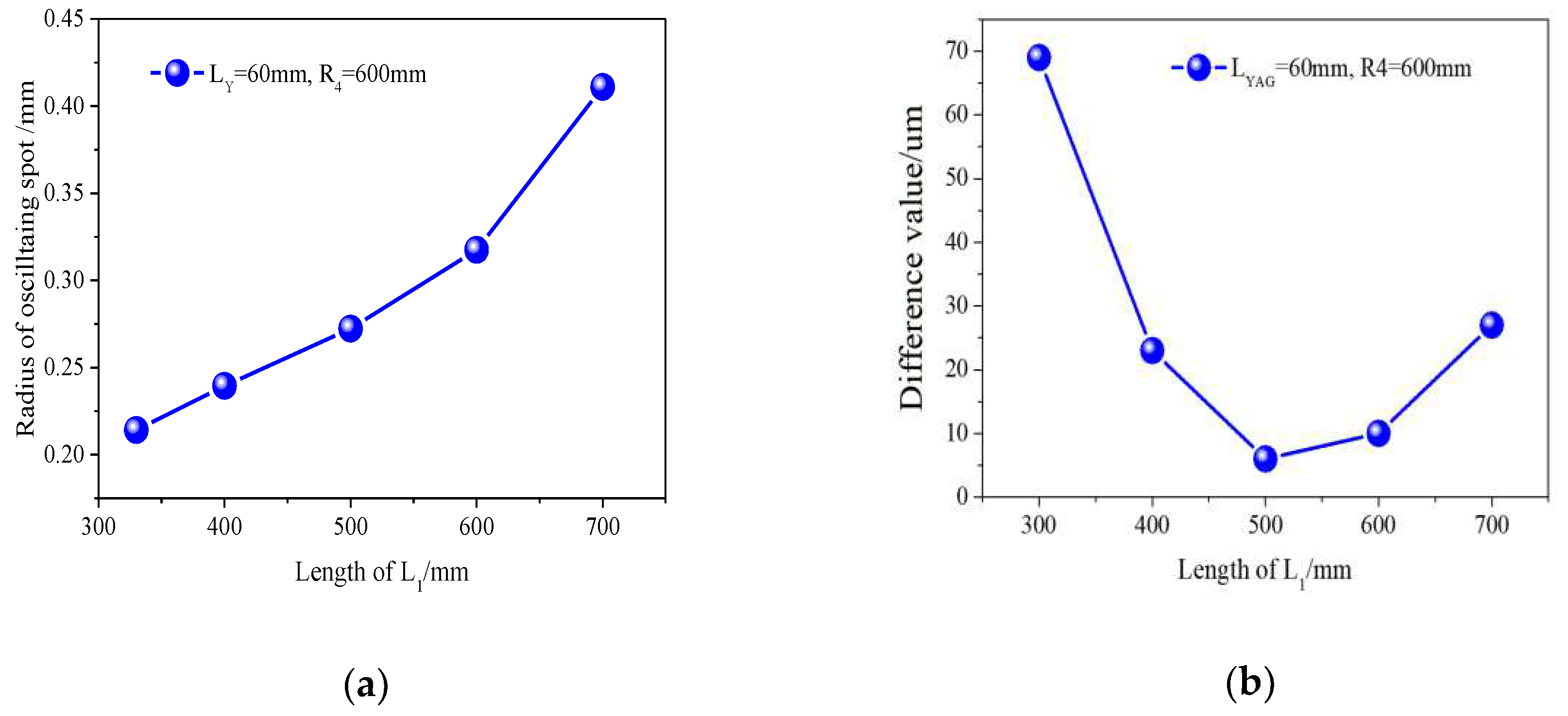
Figure 4.
Stable region state of resonator: (a) R4=300mm; (b) R4=600mm; (c) R4=2000mm; (d) R4=6000mm.
Figure 4.
Stable region state of resonator: (a) R4=300mm; (b) R4=600mm; (c) R4=2000mm; (d) R4=6000mm.
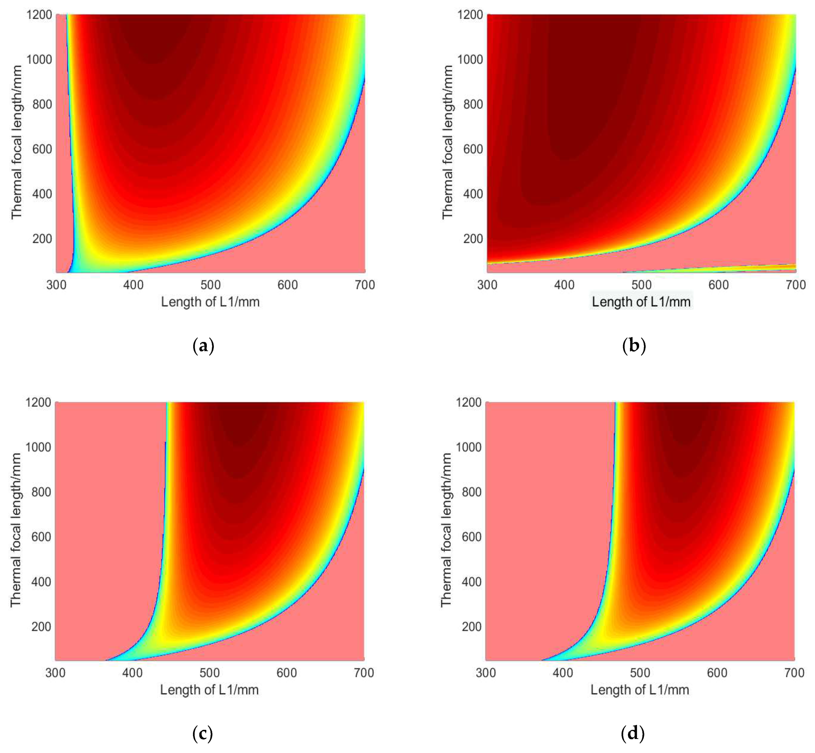
Figure 5.
Relationship between length L1 and cut-off thermal focal length under different curvature R4.
Figure 5.
Relationship between length L1 and cut-off thermal focal length under different curvature R4.
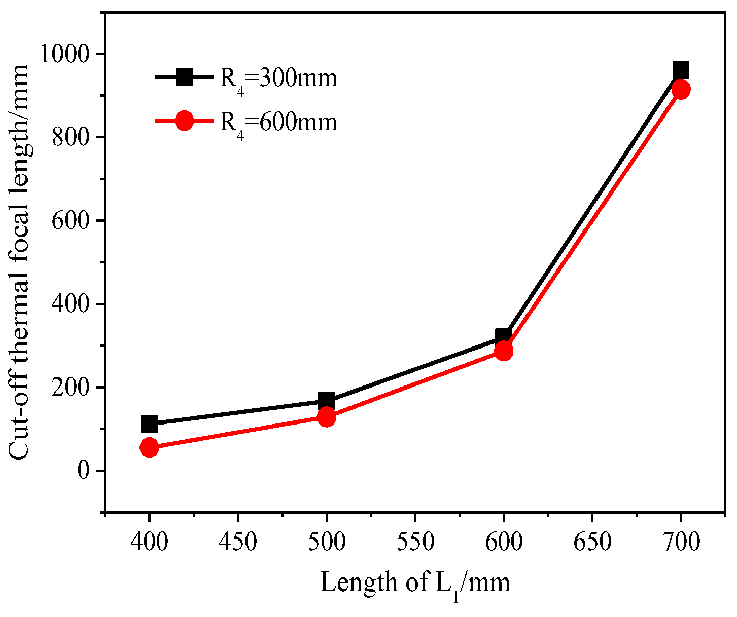
Figure 6.
Beam waist radius at different thermal focal lengths in the stable areaa) 3D View; (b) curve relationship at fth of 300mm, 500mm, 700mm, 900mm.
Figure 6.
Beam waist radius at different thermal focal lengths in the stable areaa) 3D View; (b) curve relationship at fth of 300mm, 500mm, 700mm, 900mm.
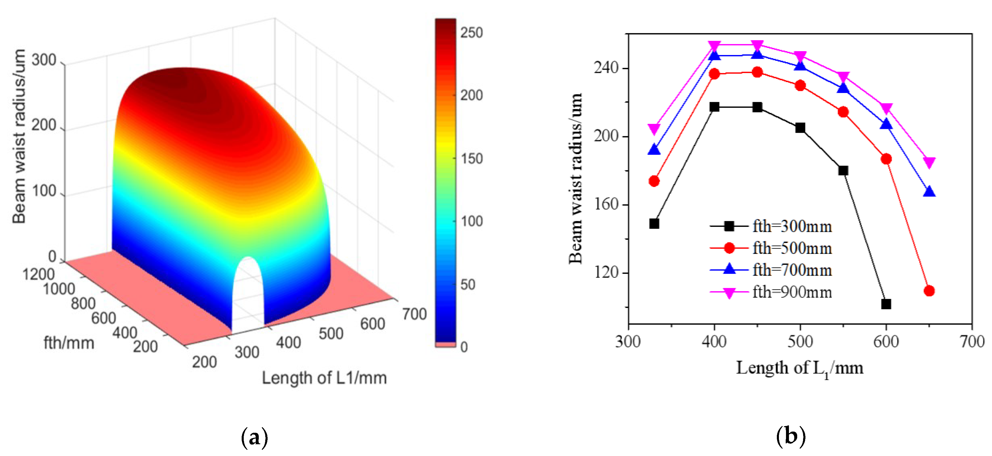
Figure 7.
Power Performance Test Results: (a) power curve at 10kHz; (b) output power stability test.
Figure 7.
Power Performance Test Results: (a) power curve at 10kHz; (b) output power stability test.
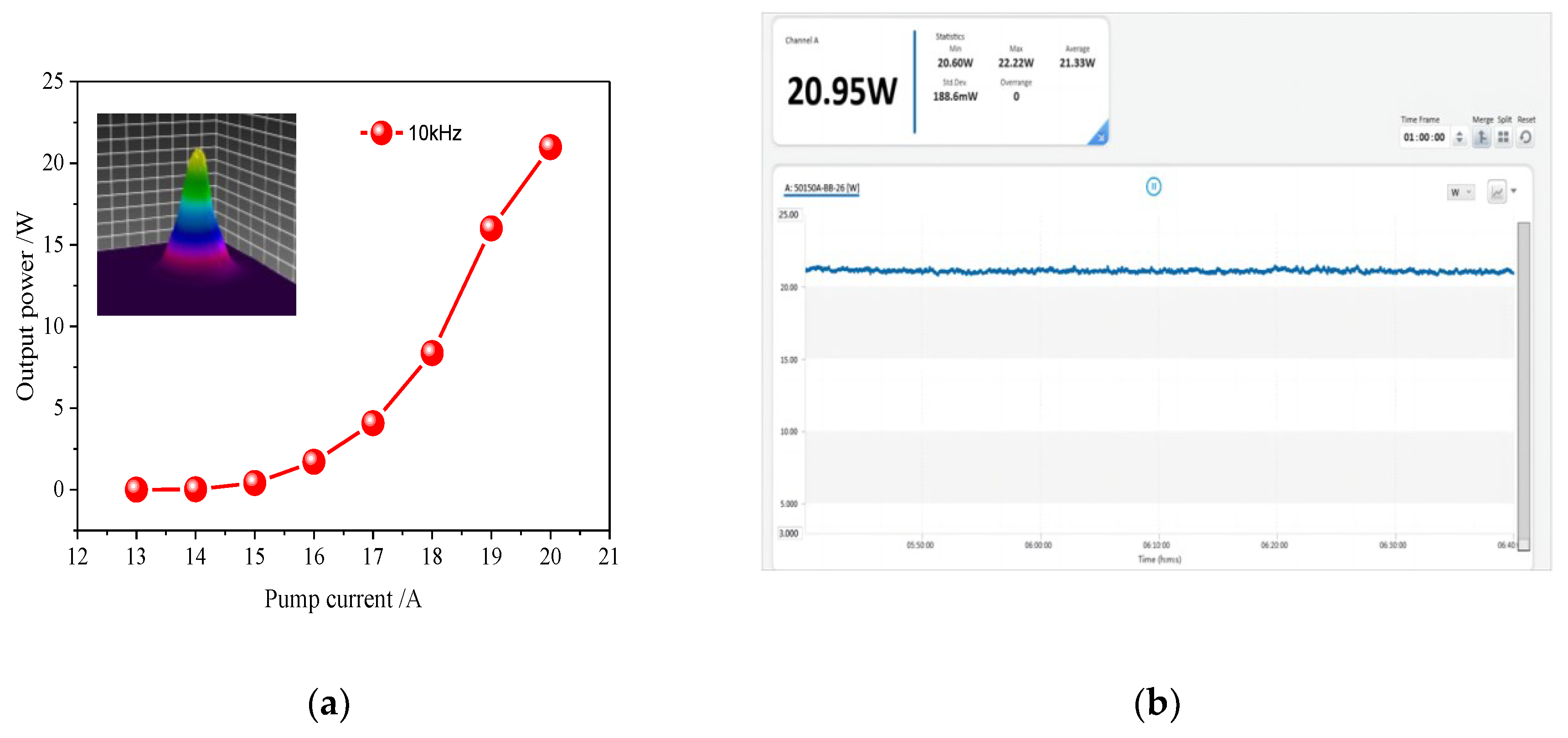
Figure 8.
Output power and single pulse energy at different frequencies.
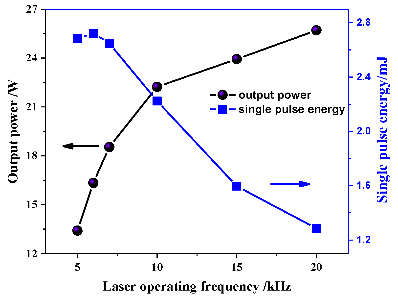
Figure 9.
Pulse width at different operating frequencies.
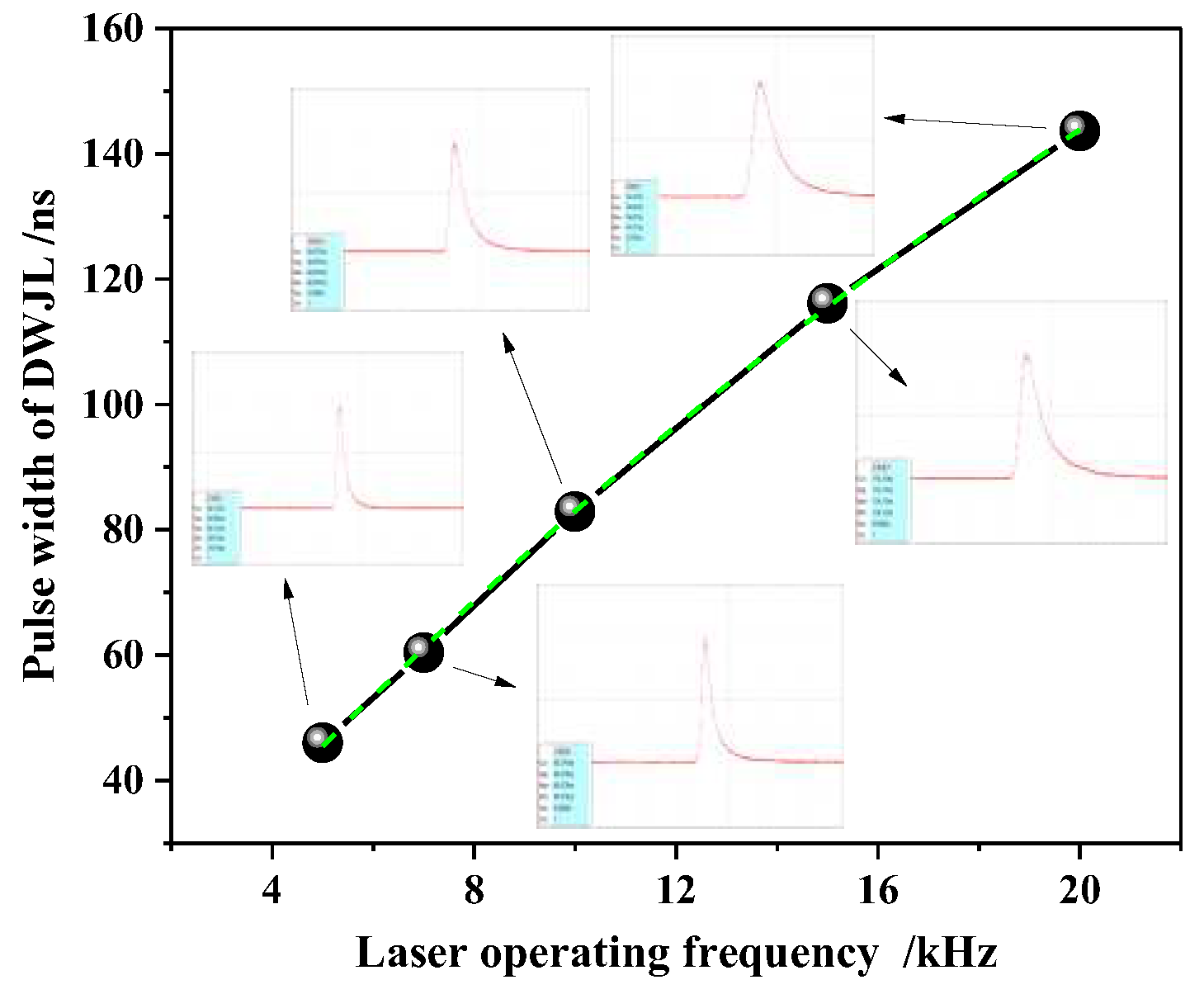
Figure 10.
Pulse width at different operating frequencies.
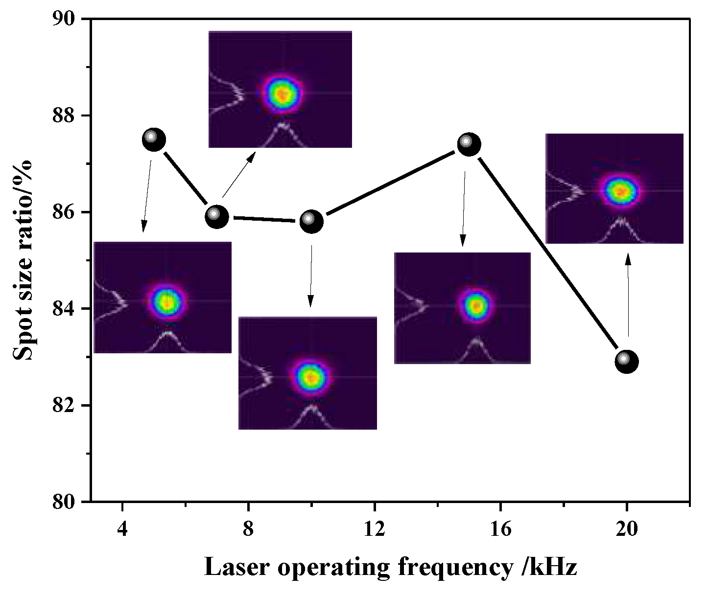
Figure 11.
Water guided laser based on the output laser pulse in this paper.
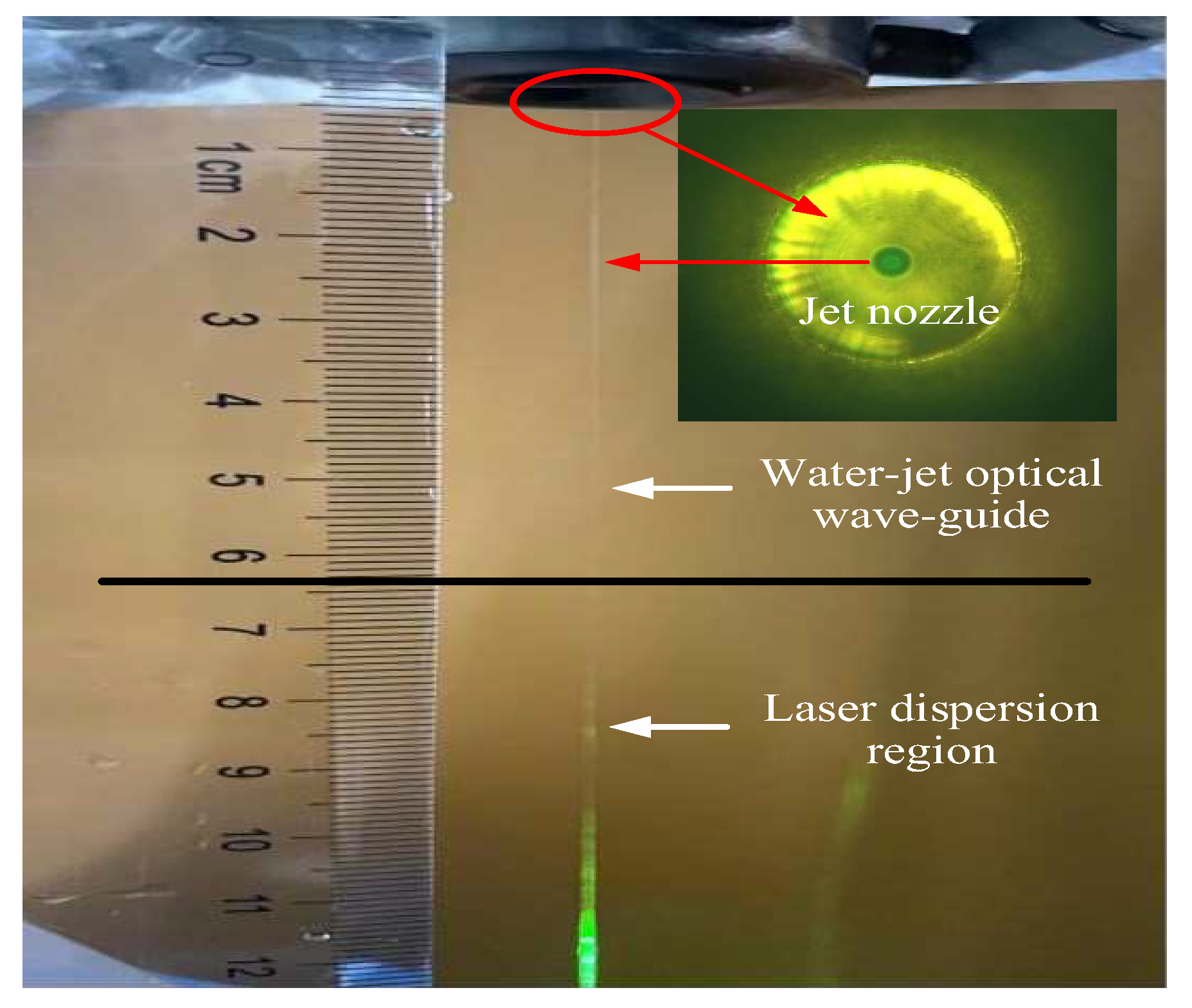
Figure 12.
Schematic diagram of oscillating beam in concave mirror resonant cavity.
Disclaimer/Publisher’s Note: The statements, opinions and data contained in all publications are solely those of the individual author(s) and contributor(s) and not of MDPI and/or the editor(s). MDPI and/or the editor(s) disclaim responsibility for any injury to people or property resulting from any ideas, methods, instructions or products referred to in the content. |
© 2023 by the authors. Licensee MDPI, Basel, Switzerland. This article is an open access article distributed under the terms and conditions of the Creative Commons Attribution (CC BY) license (http://creativecommons.org/licenses/by/4.0/).
Copyright: This open access article is published under a Creative Commons CC BY 4.0 license, which permit the free download, distribution, and reuse, provided that the author and preprint are cited in any reuse.


