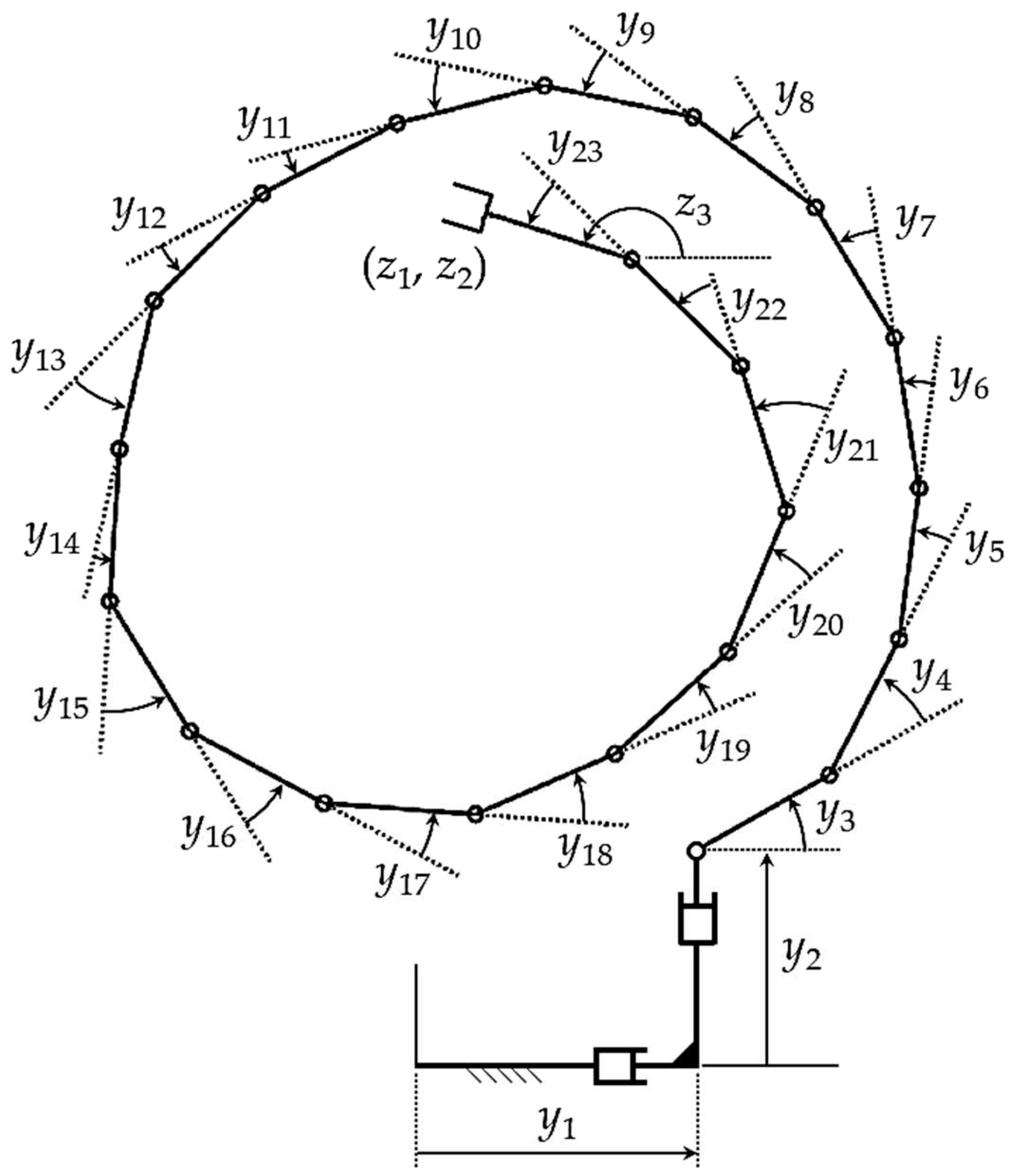
To replace the generalized inverse velocity formulation of
Section 2 with a configuration space formulation, it is required that a set-valued inverse configuration kinematic mapping be constructed; i.e., a solution
of Eq. (1) be found with an arbitrary vector of parameters
. Such a mapping has been presented in [
3] and extended in [
4] on an operational space differentiable manifold, as summarized here.
3.1. Inverse Configuration Kinematics
The entire regular configuration space
cannot, in general, be characterized by a single continuously differentiable inverse kinematic mapping. The only practical global inverse kinematic representation is based on concepts of differential geometry [
2] that employ local representations on open subsets
, whose union is the entire regular configuration space; i.e.,
. In each
, there is a
base point about which the inverse kinematic mapping is constructed. The inverse kinematic mapping process that follows takes place on each
. For a given
j and base point
in , define the
matrix
and an
matrix
such that
where
is computed as a matrix whose columns form an orthonormal basis of the null space of
in MATLAB, using
singular value decomposition [
24]. The matrices
are defined to be constant on
. Note from the second of Eqs. (13) that
and
. Since
has full rank, so do
and
. Further, since
, the columns of
are orthogonal to the columns of
and vice-versa. The n linearly independent columns of
(m columns) and
(
columns) therefore span
.
Using
and
of Eq. (13), any solution of Eq. (1) for
y in a neighborhood of
can be written in the form
where
are values of
v and
u associated with
on the trajectory that first enters
. They are introduced to assure continuity of
y as a function of
v and
z. On
,
and
. Note that, at
in Eq. (14),
. To see that there is a unique solution of Eq. (1) with
y of Eq. (14); i.e., a unique solution of
for
u as a function of
z and
v in a neighborhood of
and
, the derivative of the left side of Eq. (15) with respect to
u, evaluated at
, is
, which is nonsingular. Thus, the implicit function theorem [
25] implies existence of a unique, twice continuously differentiable solution
of Eq. (15) in a neighborhood of
. From Eq. (14),
This is the desired set-valued inverse position kinematic mapping on .
If
are periodic of period
on
; i.e.,
and
, since Eq. (17) holds throughout
,
Thus,
is periodic of period
and the manipulator is
cyclic on
. This shows that, with the differentiable manifold formulation. the manipulator is
locally cyclic. For more detail regarding cyclicity, see [
22].
The role of the function
is important in assuring satisfaction of Eq. (1). This is in contrast with the generalized inverse velocity approach presented in
Section 2, in which Eq. (1) is ignored. A computationally efficient iterative method for evaluation of
is presented in [
3,
4] and summarized in
Section 3.2. In this computation, when the number of iterations required for convergence exceeds a specified tolerance, the associated configuration
is designated
, the associated
y,
v, and
u are designated
,
, and
, a new neighborhood
is entered, and the parameterization is redefined. As shown in [
26] for dynamic system simulation, less than 0.1% of CPU time and no user interaction is required for this reparameterization. For more detail on the process of selecting configurations
and reparameterization calculations, see [
3,
4,
26].
For a given output
, with
arbitrary in a neighborhood of
v =
, Eq. (17) defines a set of input coordinates,
called the
manipulator self-motion manifold in input space associated with output
. Since
is the solution of Eq. (15),
=
0, for all
v in a neighborhood of
v =
,
of Eq. (17) maps into
; i.e.,
. Components of the vector
are called
self-motion coordinates. With arbitrary self-motion coordinates
v in a neighborhood of
, Eq. (17) defines
redundant degrees of freedom of the manipulator that enable it to meet requirements that could not be met with a nonredundant manipulator. The restriction of
v to a neighborhood of
in the foregoing is to meet hypotheses of the implicit function theorem. As will be shown in
Section 3.5 and 4.2, Eqs. (17) and (19) may hold for large
v in applications.
It is important to note that the self-motion manifold of Eq. (19) is defined at the configuration level. Since configuration information is not defined in the generalized inverse velocity formulation, the self-motion manifold and self-motion coordinates cannot be explicitly defined and are not available for obstacle avoidance and other performance optimization functions in the velocity-based formulation.
3.3. Operational Space Differentiable Manifold
Defining manipulator operational coordinates
and manipulator functional coordinates
, the manipulator regular configuration space is
Similar to the definition of the manipulator configuration space of Eq. (2) as the product of input and output spaces, the serial manipulator regular configuration space is defined as the product of input and operational spaces. This is important in establishing as a differentiable manifold.
From Eq. (17),
, and the forward kinematic mapping of Eq. (1) defines a parameterization of
,
, for arbitrary
y in a neighborhood of
, and its inverse is
. Thus,
is a differentiable manifold [
2] that is parameterized by input coordinates
y. Conversely, the inverse kinematic mapping of Eq. (17) enables the parameterization,
of
on
and its inverse is
. The set
and mapping
comprise a
chart [
2], denoted (
,
). Thus,
may also be parameterized by operational coordinates
w. This duality of input and operational space coordinates provides the foundation for analytical and numerical representation of redundant serial manipulator kinematics and dynamics [
4]. Because of its importance in manipulator operational space kinematics and dynamics [
9,
10],
is called the
operational space differentiable manifold.
A family of charts (
,
), called an
atlas, is defined to cover
, such that the mappings
are
compatible and
is a differentiable manifold that is parameterized by
w [
2]. The operational space differentiable manifold for a redundant manipulator can thus be parameterized by either
y or
w. It cannot, however, be parameterized by only output
z. Kinematics on
must be carried out on individual charts
and transitioned to adjacent charts as manipulator configurations progress along a trajectory in
, as shown schematically in
Figure 5. As explained in
Section 3.2, piecewise analysis on charts is unavoidable since, in general, there is no globally valid operational coordinate parameterization
of
. This attribute of differential geometry that transforms local to global properties of sets and mappings is one of its greatest contributions. The unavoidable reality, however, is that one must adopt local operational space parameterizations, since no global parameterization generally exists.
3.4. Differentiable Manifold-Based Output Trajectory Tracking and Obstacle Avoidance Algorithm
An output trajectory tracking and obstacle avoidance algorithm based on the inverse mapping of Eq. (17) is presented carry out kinematic control more rigorously and efficiently than the generalized inverse velocity-based method of
Section 2.2. In [
3], the inverse mapping was employed to avoid collisions in redundant manipulators using an algorithm that marched along 1-dimensional self-motion manifolds. The basic idea of that algorithm is explained, assuming that the degree of redundancy is 1. First, set a nominal trajectory
for the inputs
that yields the desired output trajectory
, without exploiting kinematic redundancy. When the manipulator starts to move, it follows this nominal trajectory until a collision is detected for some value
of the desired output trajectory (i.e., until the intersection of two bodies is not empty). When a collision is detected, the algorithm presented in [
3] performs self-motions defined by Eq. (19) that keeps
; i.e., the self-motion coordinate
is varied on a grid with a given step
along one direction (or the opposite) of the self-motion manifold until the interference disappears. Note that this algorithm is feasible only when the self-motion manifold is 1-dimensional, because one only needs to march along self-motion curves, exhaustively searching until a collision-free configuration is found.
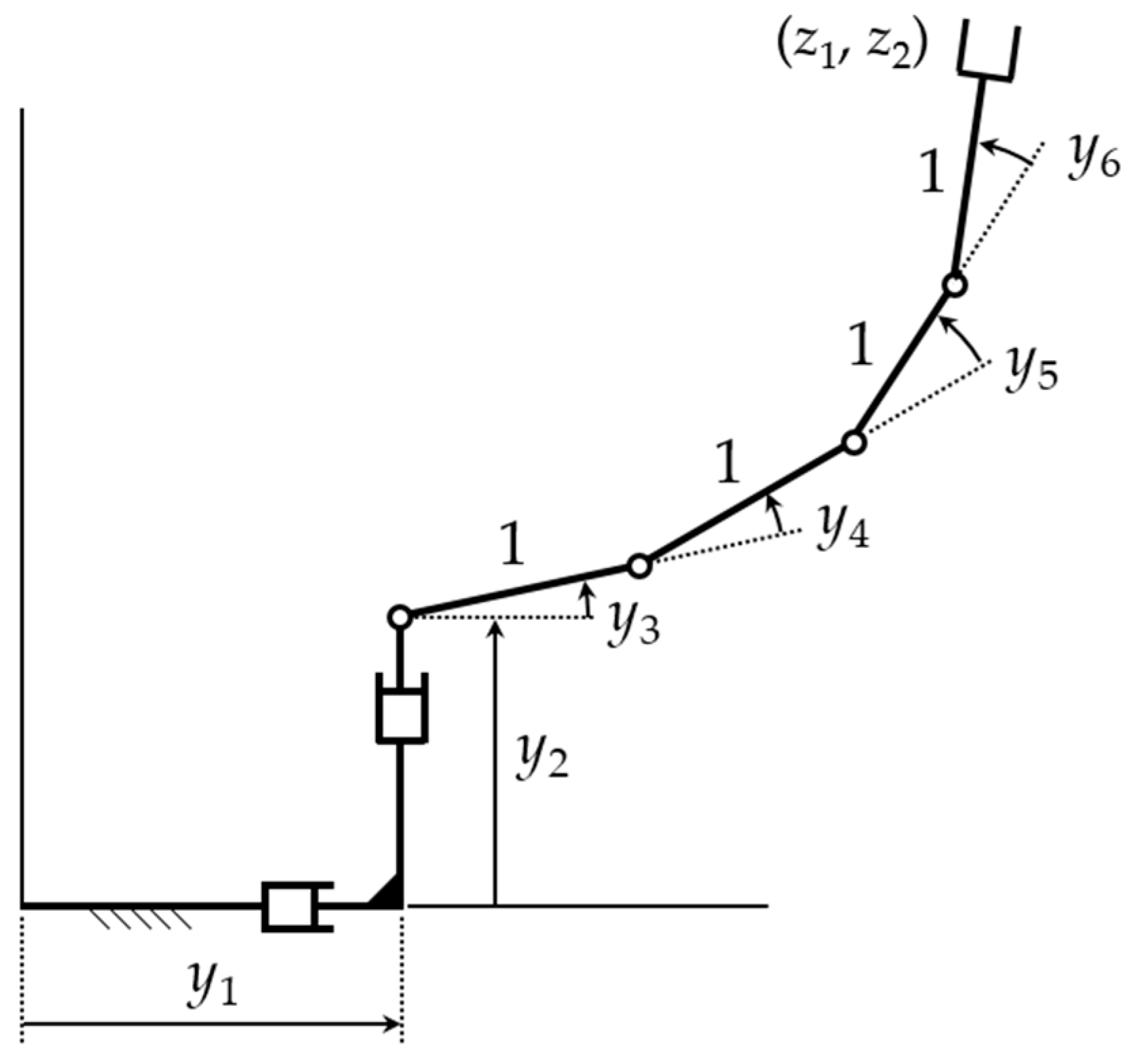
In manipulators with higher degrees of redundancy, such as the manipulator of Section 1.1.1, the obstacle avoidance algorithm used in [
3] is not feasible, because one would need to perform an exhaustive grid search in the higher-dimensional space of self-motion coordinates
, which would be computationally prohibitive (e.g., a 4-dimensional grid for the manipulator of Section 1.1.1). The new algorithm employed herein efficiently treats obstacle avoidance using the inverse mapping of Eq. (17) for higher degrees of redundancy, as the examples that follow demonstrate.
The new algorithm is based on the fact that, in the vicinity of a contact between two bodies, it is possible to define a gap function
[
27,
28] that is the signed distance between the closest points of the two bodies along their common normal. This works even when one of the bodies has a nonsmooth shape and does not have a unique normal at the point of contact [
27,
28].
Figure 6 illustrates this gap function
. Note that
is a
signed distance, which is positive when the bodies do not intersect, zero when their boundaries touch, and negative when one body has penetrated the other. The gap function
depends on the relative pose of the contacting bodies, which is defined by input coordinates; i.e.,
. Using the inverse mapping of Eq. (17), one can write the gap function in terms of the operational coordinates, i.e.,
.
Taking the foregoing into account, the new algorithm is as follows:
Initialize and select a time step . The desired output trajectory is for . The initial configuration yields the initial desired ; i.e., . Construct the inverse mapping of Eq. (17) in a neighborhood of ; i.e., compute and V and initialize = 0 and u = 0. Throughout execution of the algorithm, the self-motion vector v is updated only when necessary to avoid obstacles. If other secondary goals are to be met, the self-motion vector v can be used to optimize these secondary goals. In the present algorithm, the focus is on use of redundancy only for obstacle avoidance.
Set
, solve for
as in
Section 3.2, and evaluate
of Eq. (17). Whenever necessary, perform a reparameterization; i.e., a transition between charts illustrated in
Figure 5, as outlined in
Section 3.3.
For the computed configuration , check if interferences occur; i.e., if any link of the manipulator intersects an obstacle. If no intersections occur, continue with step 4. Otherwise, go to step 5.
Send the collision-free configuration to the controller of the manipulator and proceed to the next time step; i.e., update . If , return to step 2. Otherwise, the desired trajectory has been completed and the algorithm ends.
If the algorithm has reached this step, there exists mechanical interference between the manipulator and at least one obstacle for the current value of , which is obtained from and . Assume that contacts have occurred between links of the manipulator and obstacles. In that case, contacts define gap functions , , which will be negative because obstacles are penetrated. The objective is to find a value of v that renders the gap functions non-negative. This can be formulated as the following nonlinear system:
where
is a vector of auxiliary variables that are introduced to transform the desired inequalities
into equivalent equalities
. Next, Eqs. (23) are solved for
, using the Newton-Raphson (N-R) method [
24], where the starting values of
v and
k for N-R iteration are
v =
v* (i.e., the value that produced the interference that led to this step of the algorithm) and
k =
0. Note that, since Eqs. (23) are
c equations in (
c +
n -
m) unknowns, they comprise an underdetermined system. Therefore, when inverting the Jacobian used in the N-R method, the minimum-norm Moore-Penrose pseudoinverse is used, which updates the unknowns
r with the vector Δ
r of minimum norm. The N-R method used to solve Eq. (23) is as follows:
define
define as the Jacobian of with respect to r.
set
set iterations = 0
do
while
AND iterations < max_iterations
Since the increment Δr with minimum norm is used in Eq. (24) to update the unknowns, this favors continuity of the configuration of the manipulator. In fact, as the following examples will demonstrate, the algorithm generates continuous trajectories for the manipulator, and execution of step 5 (whose objective is to find a new value of self-motion coordinates v that avoids collisions) takes only a few milliseconds on a modern computer. The N-R method stops when a solution that satisfies Eq. (23) is found, or when a maximum of max_iterations is exceeded. In the first case, the algorithm yields a configuration y that is collision-free, and the algorithm jumps to step 4. In the second case, the desired trajectory can be considered as infeasible, because no configuration (sufficiently near to the configuration at the previous time step) can be found to continue executing the trajectory while avoiding obstacles, and the algorithm ends.
3.5. Four Degree of Redundancy Differentiable Manifold-Based Example
In this section, the algorithm of
Section 3.4 is used to solve the problem treated in
Section 2.3, where the manipulator with 4 degrees of redundancy must track the periodic trajectory given in Eq. (12). The manipulator starts at the same configuration
as in
Section 2.3. The same time step
seconds is used but, unlike in the generalized inverse method, no numerical integration is required in the algorithm of
Section 3.4, where the time step is used only to progress in time according to step 4 of the algorithm.
The algorithm described in
Section 3.4 was run with the following parameters:
when iterations > 10 = max_iterations
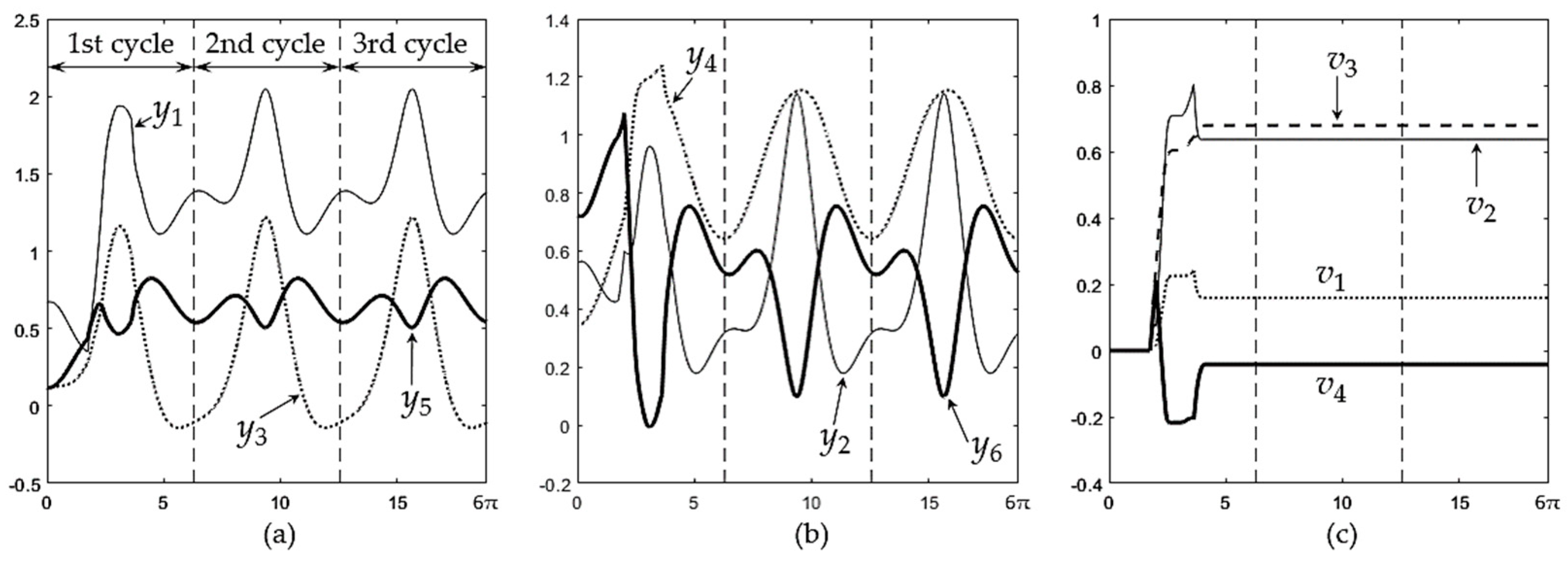
With these parameters, the algorithm generates the time histories of
y(t) and
v(t) shown in
Figure 7. As this figure shows, the time history of these variables is periodic after the first cycle. In particular,
v is constant after the first cycle. It can be seen in
Figure 7 that the trajectory of
y(t) becomes cyclic when
v becomes constant, even before the output trajectory of Eq. (12) has completed its first cycle.
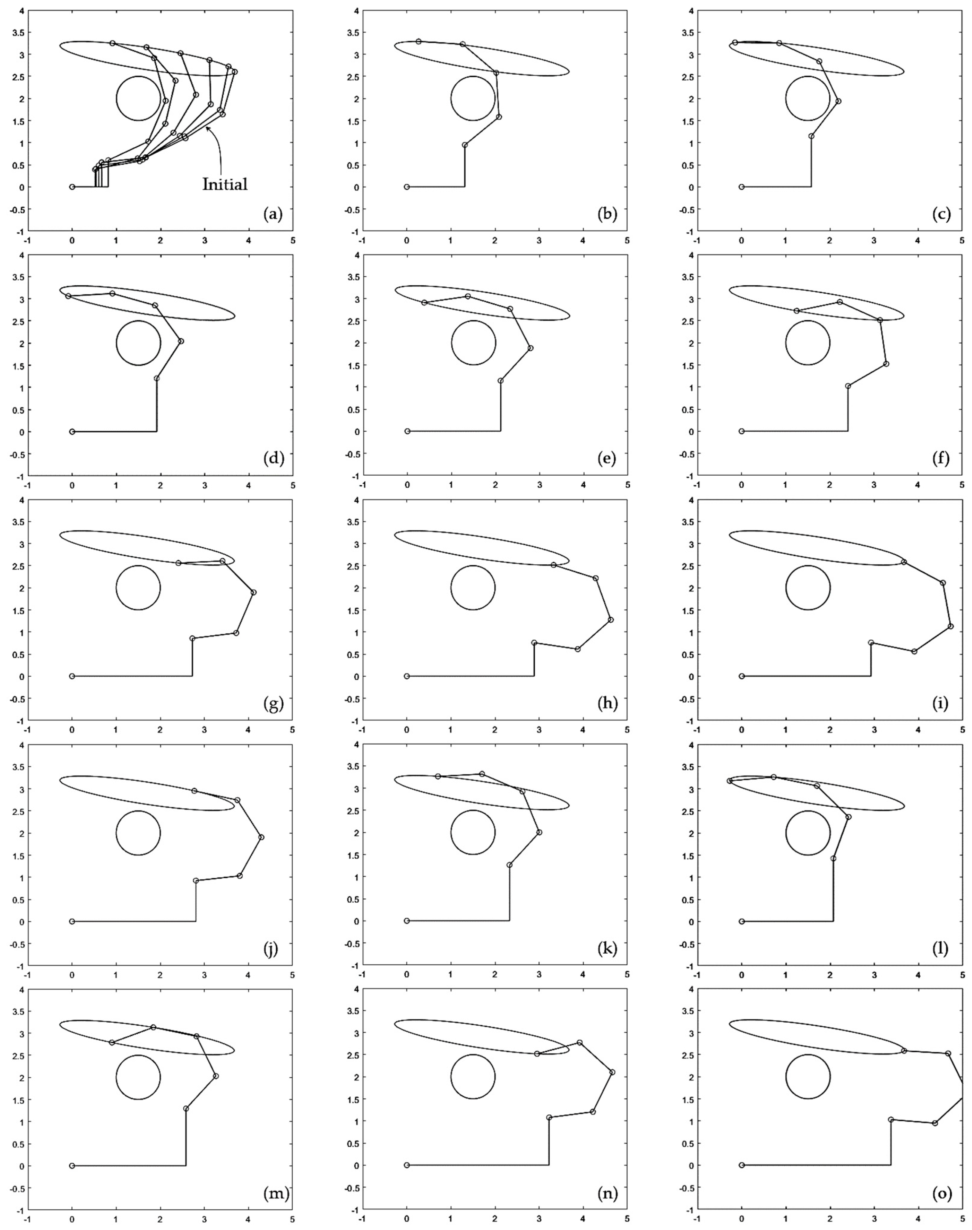
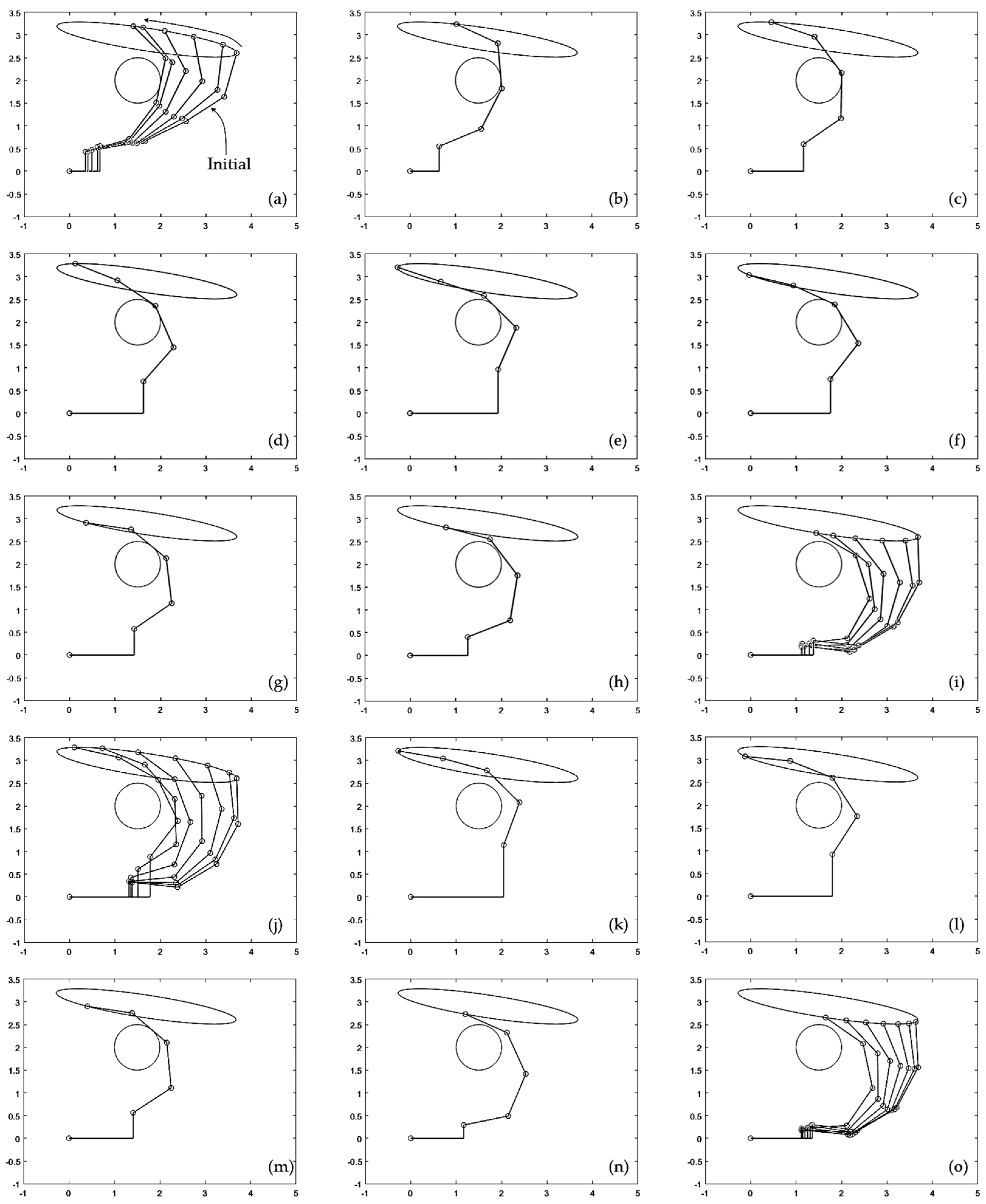
Snapshots of the manipulator executing this trajectory are shown in
Figure 8 .
Figure 8.a-i show execution of the first cycle. In
Figure 8.a, the manipulator moves with
v = 0 as it approaches the obstacle, until touching it. Then, the algorithm of
Section 3.4 starts to actively update
v(t) to avoid penetration of the obstacle.
Figure 8.b-g show how the manipulator continues tracking the desired eliptical trajectory, while some of its links touch the obstacle, until contact is lost in
Figure 8.h and
v is no longer updated. After this, the manipulator continues executing the trajectory far from the obstacle until it completes the first cycle, as shown in
Figure 8.i.
Execution of the second cycle begins with the manipulator approaching the obstacle, as illustrated in
Figure 8.j. As shown in
Figure 8.k-n, during the second cycle the manipulator is not in contact with the obstacle except during a very short period of time shown in
Figure 8.m, in which one of the links becomes tangent to the obstacle. This contact period is very short, as can be better observed in the supplementary animation S2 attached to the paper. After this short contact is lost (
Figure 8.n), the manipulator continues moving far from the obstacle until completing the second cycle (
Figure 8.o). The third and subsequent cycles are identical to the second cycle described here, as shown in
Figure 7.
As
Figure 7 and
Figure 8 show, during the first cycle of the desired trajectory given by Eq. (12), the algorithm described in
Section 3.4 actively updates
v(t) to prevent penetration of the obstacle during contact. After contact is lost,
v(t) does not need to be further updated and the input trajectory becomes cyclic, by virtue of Eq. (18). Interestingly, the constant value that
v(t) adopts after contact is lost in the first cycle allows the manipulator to continue repeating subsequent cycles during which contact without penetration occurs only during a very short fraction of the cycle, as illustrated in
Figure 8.m.
The average time required to run step 5 of the algorithm is 1.2 miliseconds (time measured on the following CPU running Maltab R2022b: Intel Core i7-8750H at 2.20 GHz). This is the time required to find a new value of self-motion coordinates that avoids penetration of obstacles every time that such penetration is detected, which demonstrates a rapid correction of the trajectory to avoid obstacles, compatible with real time requirements.
As shown in
Figure 8, to prevent obstacle penetration, the algorithm of
Section 3.4 keeps the links in contact with the obstacle and moving smoothly around it until contact is lost, as required by the trajectory of the end-effector. If it were necessary to avoid the obstacle without contacting it, leaving some safety distance
, then one would only need to change the gap functions in Eq. (23) to
, making it easier to accurately regulate distance to obstacles than with the generalized inverse velocity-based approach illustrated in
Section 2.3.
