Preprint
Article

(Ti, Nb)(C, B)/IN625 In-Situ Reactive Coating Prepared by Ultra-High Speed Laser Cladding: Interfacial Characterization, Residual Stress and Surface Wear Mechanisms

Altmetrics

Downloads

81

Views

20

Comments

0

A peer-reviewed article of this preprint also exists.

Submitted:

16 November 2023

Posted:

17 November 2023

You are already at the latest version

Alerts
Abstract
The (Ti, Nb)(C, B)/IN625 composite coating with both homogeneous and defect-free microstructure were successfully prepared by in situ on the surface of 42CrMo steel using the coupling of the ultra-high-speed laser cladding (EHLA in German) technology with the direct reaction synthesis (DRS) technology, and were comparatively analyzed with the IN625 coating prepared by the EHLA. The microstructure of the fused cladding layer was investigated by selected scanning electron microscopy (SEM), energy dispersive spectrometer (EDS) and double spherical aberration transmission electron microscopy (DSA-TEM). The residual stress distribution on both sides of the fused cladding interface was characterised by nanoindentation stress test based on the modified O&P method and the G&S energy method. The results show that the interface of (Ti, Nb)(C, B)/IN625 composite coatings is affected by about 670 kJ Joule heat released from the in-situ reaction, and the interfacial width reaches 24 μm, so that it is 6 times higher than that of IN625 coating prepared by EHLA, which effectively reduces the stress gradient in the interfacial region and alleviates the stress mismatch on both sides of the interface. However, the surface hardness of (Ti, Nb)(C, B)/IN625 composite coating is lower than that of the IN625 coating, with a value of about 240 HV0.2, and the average wear weight loss was only 10% of that of the IN625 coating, which is on the one hand attributed to the in-situ authigenic TiCB, TiC, NbMo3B4, and NbMo2B2 phases supporting the (Ti, Nb)(C, B)/IN625 composite coating substrate to achieve the abrasion reduction and wear resistance. On the other hand, it is attributed to the formation of nano-equiaxial ultrafine grains in the depth range of 250 nm below the wear surface area by the coupling of the three fields of plastic rheology-heat-force, which dynamically strengthens the wear surface.
Keywords: 
Subject: Chemistry and Materials Science  -   Surfaces, Coatings and Films

1. Introduction

Ultra-high-speed laser cladding (EHLA) has the advantages of high coating preparation efficiency [1], thin thickness [2], low dilution rate [3], high powder utilization [4], and high coating densities [5], which makes EHLA a green and advanced coating preparation technology with more potential than traditional laser cladding, and it has been popularized and applied in various industrial fields such as engineering machinery, aerospace, and so on [6,7].
Ni-based alloys with excellent impact toughness, corrosion resistance, oxidation resistance, wear resistance as well as reasonable price have been widely used in the field of laser cladding technology and have received attention from scholars [8,9,10,11]. Among them, Asghar et al [9] prepared a dense and defect-free Ni60 coating by EHLA, which consisted of supersaturated γ-Ni and some in situ precipitated hard phases (e.g., carbides or borides of Cr, etc.), and the average hardness of the coating reached 948 HV, with a significant improvement in wear resistance. However, with the increase of the melting rate, the heat accumulation absorbed by the substrate decreased, resulting in a significant reduction of both the dilution rate and the heat affected zone (HAZ) of the substrate [12]. When the melting rate was increased from 0.6 m/min to 76.6 m/min, the width of the HAZ for the Ni45 coating decreased from about 400 μm to about 50 μm, and at the same time, the width of the melting interface also suddenly dropped from about 150 μm to about 3 μm [8]. Although the reduction of the interface width led to a significant improvement of the shear mechanical properties at the interface location [13], it was easy to form a stress mutation at the fusion-coated interface due to the difference in the coefficients of thermal expansion between the coating material and the substrate material, in addition to the existence of a high temperature gradient and a chemical composition gradient at the location of the EHLA interface, which made the interface location become the weakest section [14].
TiC and TiB2 ceramic phases have the advantages of high hardness, excellent wear resistance, good thermal stability [15,16], and good wettability with IN625 alloy [17,18]. The ultrahigh-speed laser-melted IN625 coatings obtained by direct introduction of TiC particles showed significant improvement in wear resistance, but the TiC particles showed an agglomeration effect, and the hardness and wear rate of the coatings fluctuated greatly [19]. The in-situ synthesis method of Ni-based TiC-TiB2 composite ceramic materials was originally derived from the self-propagating high temperature synthesis [20], which utilizes the exothermic material reaction to maintain the reaction system and ultimately obtain the reaction products. Direct reaction synthesis (DRS) is evolved on the basis of this method, which is characterized by rapid reaction and uniform dispersion of the enhanced phase [21]. In this paper, uniform (Ti, Nb)(C, B)/IN625 composite coating was successfully in-situ prepared by coupling EHLA technology with DRS technology. The low dilution rate of EHLA was effectively improved by utilizing the exotherm of the coating reaction system, and the stress mutation at the fused interface was effectively mitigated. The wear resistance mechanism on the coating surface was further investigated, on the basis of which the technical feasibility was explored for the in-situ preparation of metal-based ceramic composite coatings by EHLA.

2. Experimental

2.1. Coating Preparation

The rod-shape substrate for the EHLA was made of quenched 42CrMo steel with dimensions of 150mm (φ) × 300mm (L), and the surface was prepared to a final roughness of 0.2 μm Ra, then followed by alcohol cleaning before EHLA. The pre-alloyed powder for ultra-high speed laser cladding consisted of 80wt% IN625 + 20wt% (TA15+B4C), where Ti and B4C were proportioned according to the molar ratio of 3:1 as shown in Eq. 1.
The morphology of the powder after ball milling and mixing for 4 h was shown in Figure 1. The powder preparation methods, particle sizes and EDS analysis results were shown in Table 1. Ultra-high speed laser cladding of 42CrMo rod-shape substrate was carried out at room temperature using the process parameters shown in Table 2. Finally, IN625-based composite ceramic coatings and pure IN625 coatings with the same axial cladding length of 250 mm and thickness of about 0.4 mm were prepared, respectively.
3 T i + B 4 C     T i C + 2 T i B 2 + Q

2.2. Wear Testing

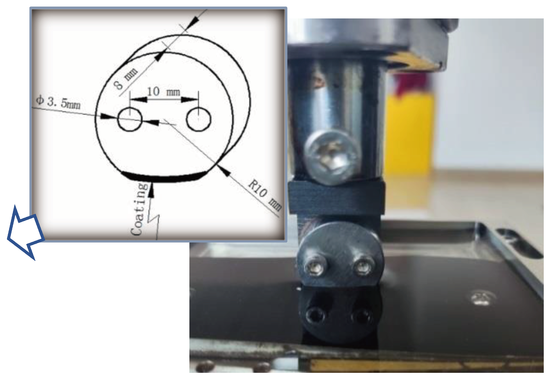
The dimensions of the wear test specimen are shown in Figure 2. The high-speed reciprocating friction and wear tester typed MDW-02 from Jinan Yihua Tribology Testing Institute was used to realize the grinding of the coating surface against 360 mesh SiC sandpaper at room temperature. During the wear test, water was used as the lubricating medium. The test force was set to 20N. The reciprocating wear distance was 30mm. And the test frequency was 2Hz. The sandpaper was replaced once after each reciprocating wear time reached 30min. A specimen cumulative wear test for 90min. Three wear specimens were taken as a group and the average weight loss was calculated at the end of the wear test.
Figure 2. Dimensions of wear specimen.
Preprints 90707 g002
Table 1. Preparation methods, particle size and EDS analysis of pre-alloyed powders.
No. Material Preparation method Particle size
(μm)
EDS (wt%)
Ni Cr Mo Si Fe Nb Ti V Zr Al C B
1 IN625 Gas-water atomization 30-70 55.46 22.85 9.94 0.24 4.11 4.96 1.21 0.32 0.28 0.32 0.10 0.21
2 TA15 PREP 15-53 3.21 0.22 0.52 0 0 0.1 82.86 2.1 1.89 7.8 0.51 0.79
3 B4C Carbothermal reduction 1-5 0 0 0 0 0 0 0.07 0.05 0.02 2.26 18.5 79.1
Table 2. Process parameters of EHLA.
Laser power
P / w
Linear velocity
vL / (m.min-1)
Axial offset
d / (mm.r-1)
Powder-feeding rate
vP / (g.min-1)
Protective airflow
g / (L.min-1)
4400 5 1.6 28 7

2.3. Microstructure Characterization

Metallographic specimens were cut from the EHLA coated sample with 15mm (L) × 10mm (W) × 8mm (H), using Electrical Discharge Machining (EDM). These specimens were polished and etched for 10-15s using a solution of 10% FeCl3-4% HNO3-86% CH3CH2OH, then the microstructure of the coating was obtained by scanning electron microscopy (SEM, typed by JSM-7200F). The distribution of elements in the interface region of the coating was analysed by energy dispersive spectroscopy (EDS, typed by XFlash5030T) with a total amount of not less than 20,000 cps. Furthermore, the cross-section samples of the coating after vibratory polishing for 4h were analyzed using electron back scattered diffraction (EBSD, typed by EDAX Velocity Super). Finally, thin slices (with dimensions of 8 μm × 8 μm × 50 nm) in the vertical direction of the wear surface from the IN625-based composite ceramic coating and the pure IN625 coating were respectively sliced by using focused ion beam (FIB), and then transferred to double spherical aberration transmission electron microscopy (DSA-TEM, typed by FEI Titan Cube 80-300) to observe the cross-sectional morphologies with accelerating voltage of 200 kV, while the elemental distribution of the ceramic particles was analyzed by energy dispersive spectroscopy (EDS, typed by Oxford Xplore).

2.4. Nanoindentation Testing

The stressed sample for the nanoindentation test was selected from the metallographic specimens described in Section 1.3 with same dimensions. A thin sheet with a thickness of only 0.4mm was cut from the original structure for further stress relaxation, which is considered as the corresponding "stress-free" sample. The pre-preparation of nanoindentation samples, the location and array of nanoindentation points, the parameters of nanoindentation testing, the modified formula for indentation projected contact area, the calculation method of residual stress based on the modification above, as well as the calculation formula of the G&S energy method are all in agreement with the method from the previous work [14]. Among them, the modified formula for indentation projected contact area Ai of a “pile-up” indentation is shown in Eq. (2).
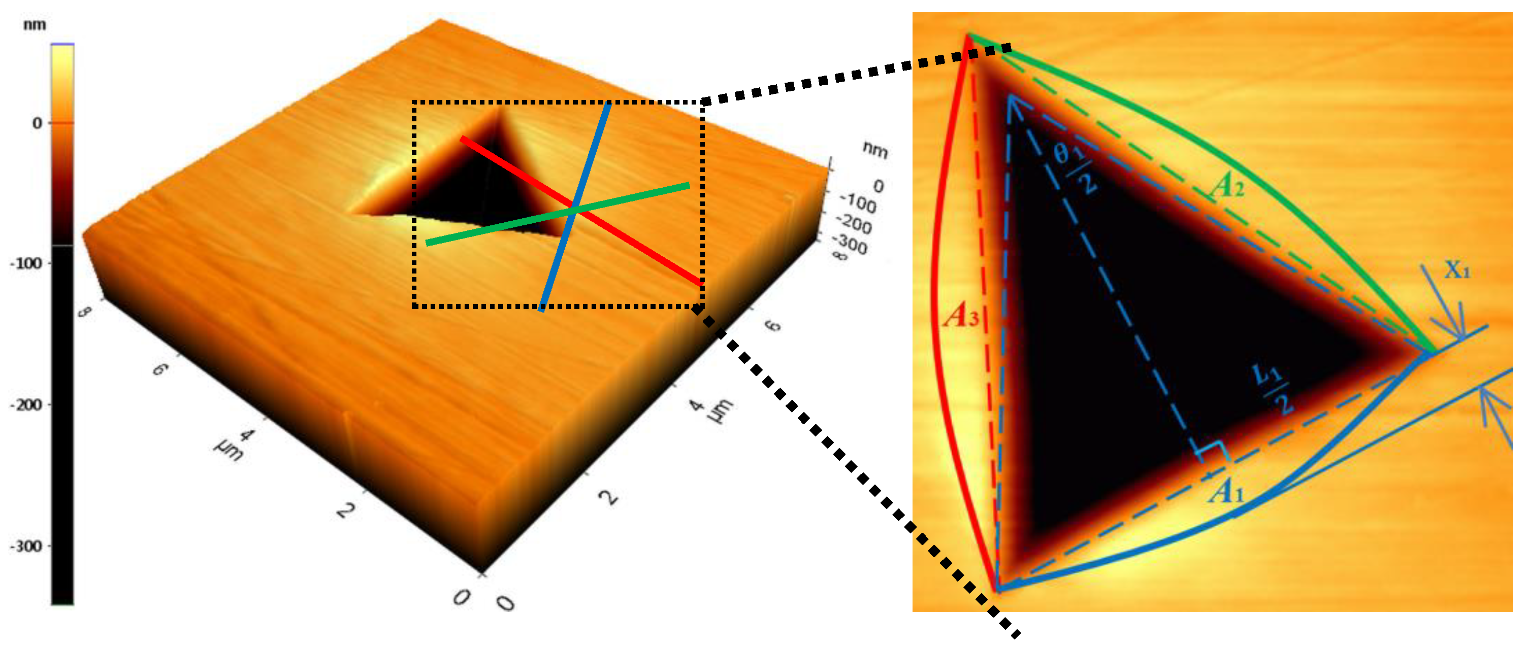
A i = θ i 360 π R 2 1 2 L i L i 2 t a n θ i 2 = L i 2 4 θ i π 360 sin 2 θ i 2 cot θ i 2
where θi was the top angle of the isosceles triangle with the base of Li (as shown in Figure 3 for 1 point of the nanoindentation). To account for pile up, Li was related to the maximum indentation depth hmax and the pile-up height hpi using Eq. (3) according to O&P model [22]:
Li=7.35(hmax+ hpi)
The geometrical relationship of isosceles triangle is shown in Eq. (4).
x i = 3.765 tan θ i 4 L i
Figure 3. Atomic force microscopy (AFM) scans taken from the residual indent # 1.
Preprints 90707 g003
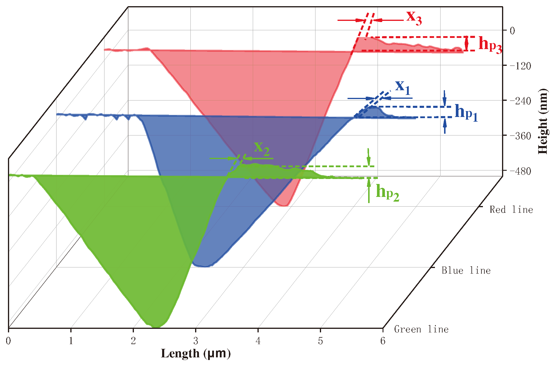
The hpi and xi obtained in Figure 4 can be substituted into Eq. (3) and Eq. (4) to obtain Li and θi, respectively, then the value of Ai can be obtained using Eq. (2). The true projected indentation contact area, A, is finally calculated using Eq. (5).
A = A o & p + 1 3 A i
Similarly, the true projected contact area of the modified "stress-free" sample, A0, also can be obtained. With known contact area, the residual stress distribution across the interface of the coating and 42CrMo steel substrate can be obtained by using Eq. (6) or Eq. (7).
σ t e n s i l e = H ( A 0 A 1 )
σ c o m p r e s s i v e = H sin α ( 1 A 0 A )
where H is the hardness obtained from the test of nanoindentation, and α is the constant of Berkovich indenter, taken as 24.7°. The sinα in Eq. (7) was introduced to account for the different response of indentation into compressive stress state and tensile state stress. When compressive stress existing on the sample surface, the decomposed uniaxial stress acted as a barrier to the indentation, so the sign in Eq. (6) could not be changed directly to obtain the residual compressive stress.

3. Results

3.1. Microstructures of Fusion Interface

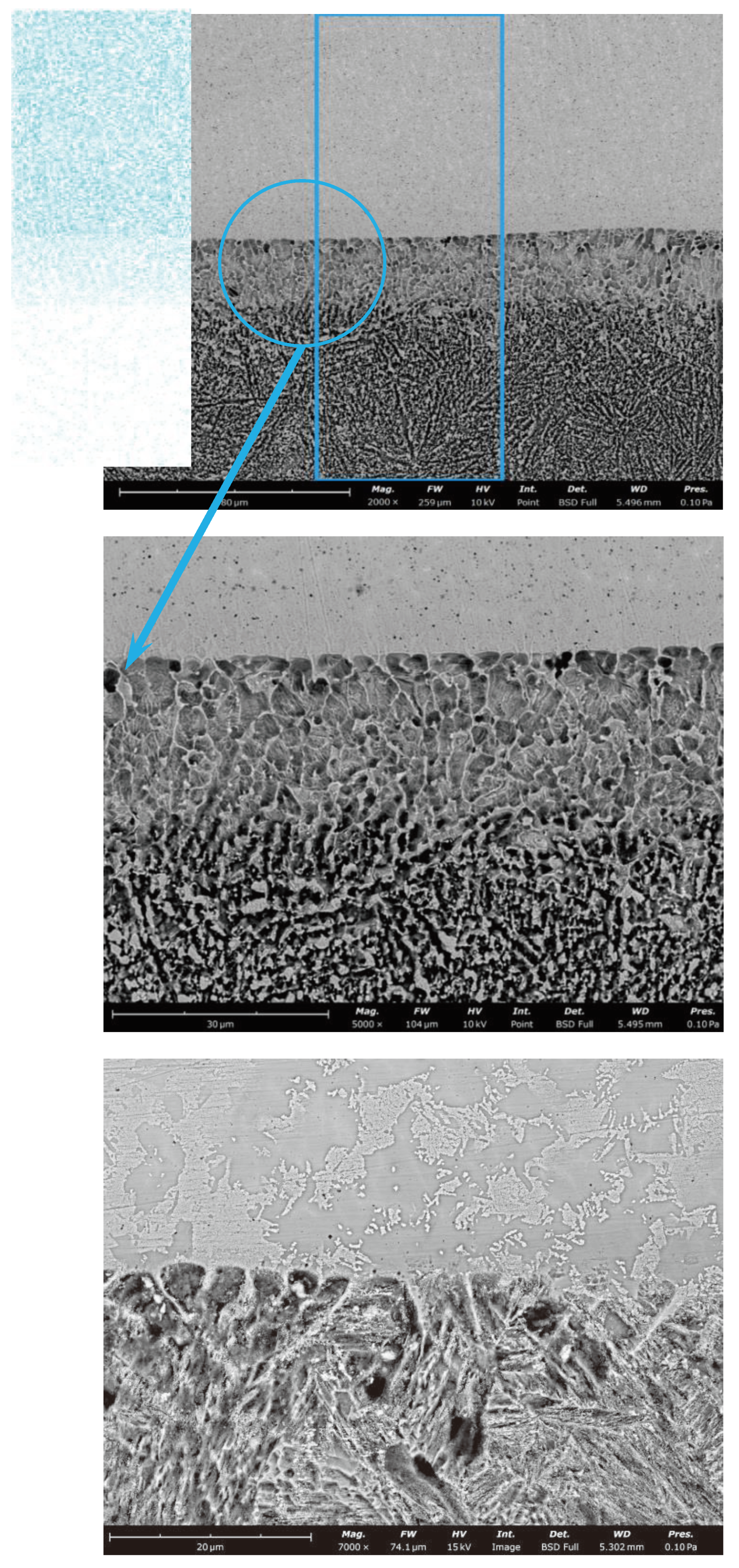
The microstructure in the fusion interface of (Ti, Nb)(C, B)/IN625 composite coating prepared by in-situ EHLA is shown in Figure 5a. The composite coating is uniform and dense in the interfacial area, and there are no obvious defects such as porosity and cracks. Compared with the average interfacial width of 4 μm for the IN625 coating prepared by EHLA shown in Figure 5c, there is a remelting-like interface, shown in Figure 5b, with an average width of about 24 μm between the (Ti, Nb)(C, B)/IN625 composite coating prepared by in-situ EHLA and 42CrMo substrate, and its value of the interfacial width reaches six times higher than that of the IN625 coating. From the facial scanning analysis of Ni in the inset of Figure 5a, it can be seen that there is a gradient distribution of Ni within the remelting-like interface, which indicates that the (Ti, Nb)(C, B)/IN625 composite coating prepared by in-situ EHLA forms an obvious and excellent metallurgical binding with the 42CrMo substrate.

3.2. Morphologies of (Ti,Nb)(C,B)/IN625 Composite Coating
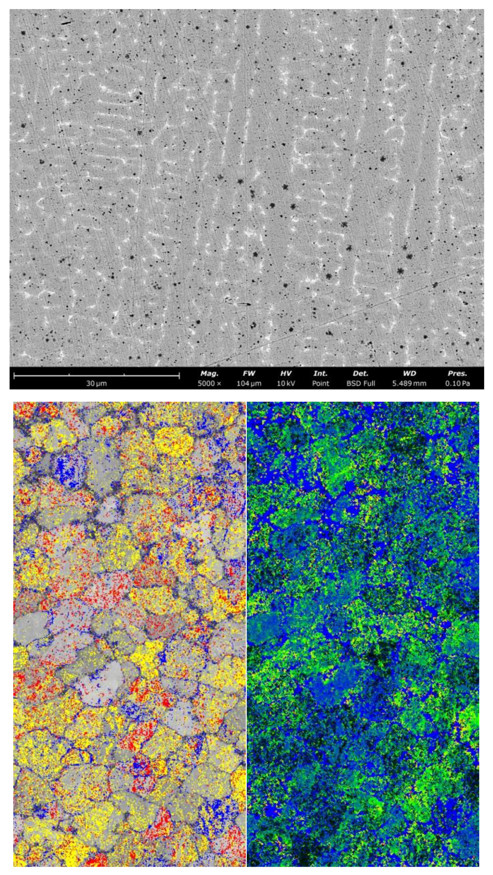
The morphology of the (Ti, Nb)(C, B)/IN625 composite coating mentioned above mainly consists of columnar crystals ( shown in Figure 6a), and diffusely distributed particle phases. (Ti, Nb)(C, B) particle phases in the composite coating show a gradient distribution along the thickness direction of the coating, which is mainly caused by the density difference existing between the coating substrate and (Ti, Nb)(C, B) particle phases, and coupled with the centrifugal force during the whole EHLA process. The phases distribution in the superficial area of the composite coating based on EBSD analysis is shown in Figure 6b, in which the Ti-C-B phases are marked in yellow, the Ti-C phases are colored in red, and the Nb-Mo-B phases, mostly distributed along the grain boundaries, are labeled in blue. As seen in Figure 5b, the number of the in-situ particle phases in the bottom area of the composite coating are significantly lower than those in the top area of the composite coating shown in Figure 6b, while the number of particle phases in the mid-area of the composite coating shown in Figure 6a is intermediate between them. Moreover, the variation of local orientation at grain boundaries and intragrains was quantified by KAM (Kernel Average Misorientation) map shown in Figure 6c. From the results, it can be seen that there are mismatch angles with no more than 5° in grains and on grain boundaries, respectively, which indicates that there is a certain strain field existing in the superficial area of the composite coating. Therefore, it is necessary to analyze the residual stresses at the fusion interface in further detail.
Figure 5. Interfacial zone morphologies of (Ti, Nb)(C, B)/IN625 composite coating (a, b) and IN625 coating (c).
Preprints 90707 g005

3.3. Stress Distribution at the Interface of (Ti,Nb)(C,B)/IN625 Coating

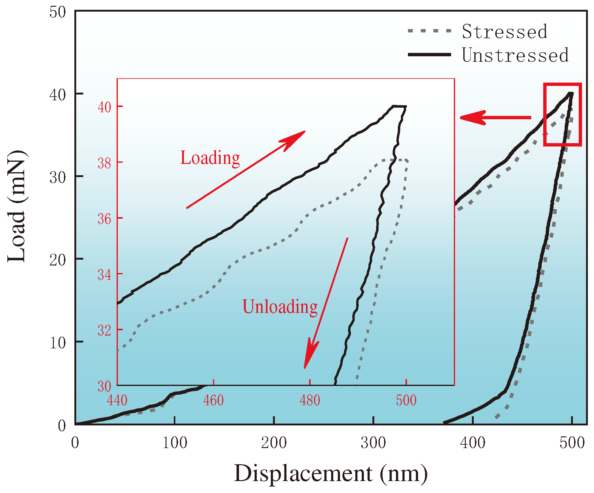
The load-displacement curve for the 1-point position shown in Figure 3 under the condition of indentation depth of 500 nm is shown in Figure 7. During loading of the coating surface, it is found that the indentation load required for the stressed coating is obviously less than that for the corresponding unstressed coating, which indicates that there is a residual tensile stress at this coating position. Moreover, when the Bohrer’s indenter is in the unloading stage, the elastic recovery of the stressed coating is relatively small, which proves that the stress at this coating position acts as resistance to the recovery process of material unloading. The above analysis can demonstrate the presence of residual tensile stresses at the 1-point location of the coating [23]. Correspondingly, the analysis for the presence of residual compressive stresses is vice versa.
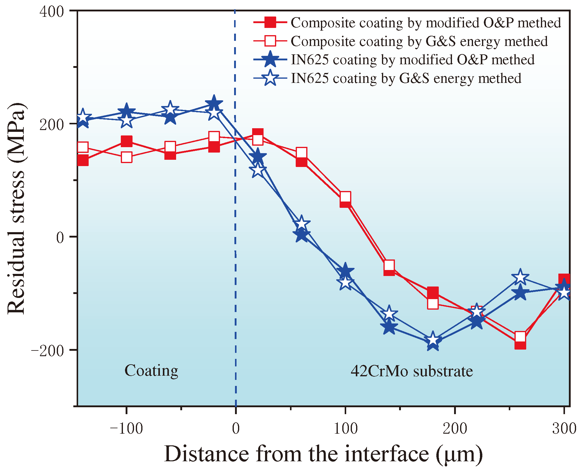
Pile-up values of all nanoindentations including 1 point shown in Figure 3 were measured by AFM. Then the true projected contact area A of all indentation points is obtained by using Eq. 5. Finally, the residual stress distribution shown in Figure 8 was obtained by selectively choosing Eq. 6 or Eq. 7 based on the combination of the load-displacement curves of all nanoindentations of the stressed samples and the corresponding unstressed samples, respectively. It is obvious in Figure 8 that there are obvious residual tensile stresses in both (Ti, Nb)(C, B)/IN625 composite coating and IN625 coating. The peak value of residual tensile stress in IN625 coating at the position of the fusion interface is about 235 MPa, and then it shows a steep drop in the heat affected zone (HAZ) of 42CrMo and enters into the state of compressive stresses. In contrast, the peak value of the residual tensile stress of (Ti, Nb)(C, B)/IN625 composite coating occurs at the coarse grain heat affected zone (CGHAZ) of 42CrMo, which is about 180 MPa, and then it shows a more moderate decreasing trend. Moreover, there is a high similarity between the residual stress values calculated by using the modified O&P method in this paper and the G&S energy method, respectively. This finding is consistent with the conclusion of a previous work [14].

3.4. Characteristics and Properties of Wear on Coating Surfaces

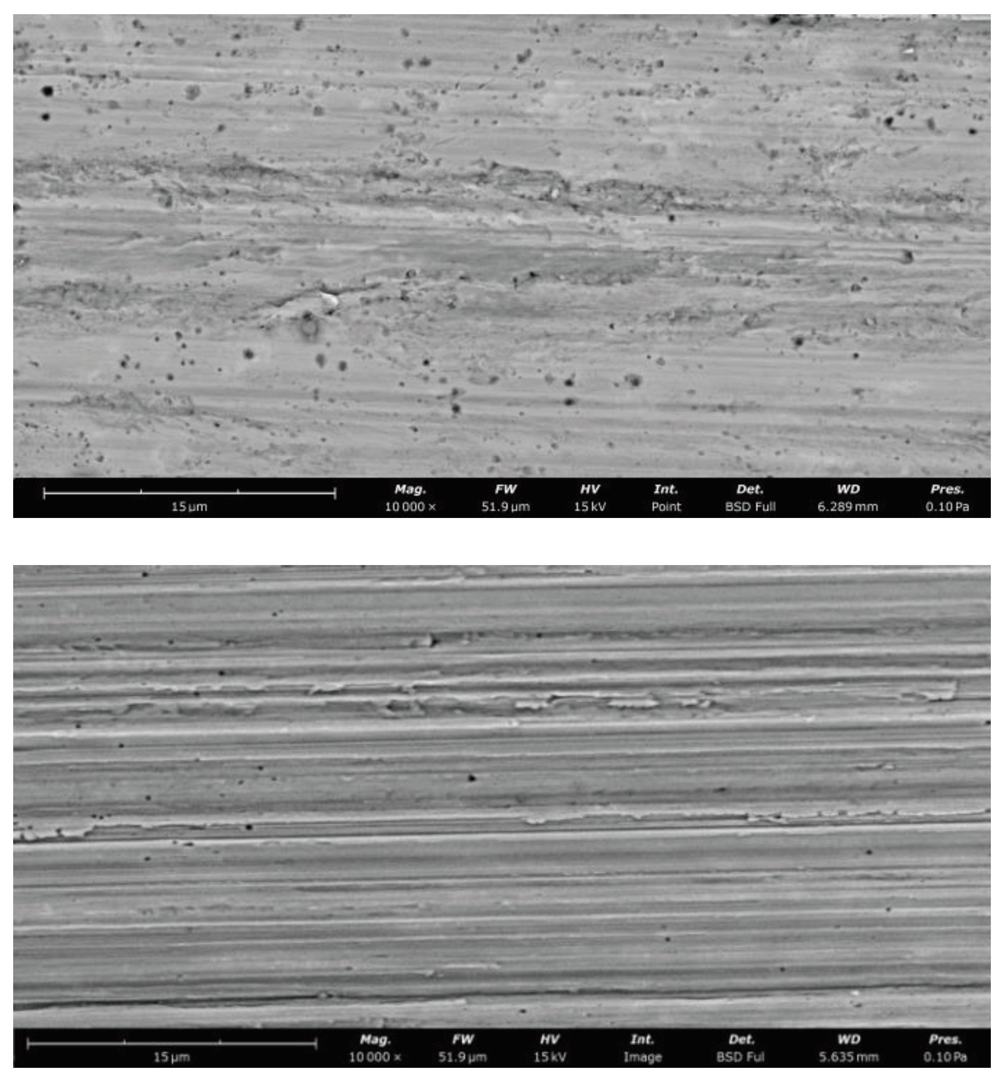
The average wear rate and average friction coefficient of (Ti, Nb)(C, B)/IN625 composite coating synthesized by in-situ EHLA is 0.012 g/h and 0.1506 respectively, and the surface wear characteristic of the coating shows the characteristics of both abrasive and adhesive wear (Figure 9a), with the surface Vickers hardness of 240 HV0.2.
The surface morphology of the IN625 coating deposited by EHLA presents only abrasive wear (Figure 9b), and the average wear rate of the surface reaches 0.121 g/h, with an average coefficient of friction of 0.3184. And the surface Vickers hardness is 300 HV0.2, which is only 60 HV0.2 much higher than that of the (Ti, Nb)(C, B)/IN625 composite coating.

4. Discussion

Compared to the EHLA melted IN625 coating, the (Ti, Nb)(C, B)/IN625 composite coating with in-situ EHLA process has the characteristic of a slow-descending residual stress distribution along the fusion interface, which is mainly owed to the reactive exothermic reaction of Ti with B4C shown in Eq. (1). Calculating the reaction exotherm of Eq. 1 usually requires the availability of standard molar free energy, which can be calculated using the Gibbs-Helmholtz equation or the Van’t Hoff equation [24]:
d G T Θ T = H T Θ T 2 d T
The Gibbs free energy, ∆G, for the in situ synthesis of TiC-TiB2 shown in Eq. (1) within Ni is lower than the synthesis of other products, that is to say, the driving force for the synthesis of TiC-TiB2 is the largest, and the stability of TiC-TiB2 is therefore naturally the highest, and the exothermic value of the reaction, Q, can reach up to 670 kJ [25]. It can be seen that an interfacial remelting zone with a width of about 24 μm is presented at the position of EHLA interface shown in Figure 5b. This indicates that, the Joule heat released from the Eq. (1) reaction during the formation of (Ti, Nb)(C, B)/IN625 composite coating is sufficient to make the original fusion interface remelted for the second time and obtain the interface with a width of 24 μm in the form of near-equiaxed crystalline morphology, so as to achieve the purposes of increasing the dilution rate of the EHLA interface, promoting the metallurgical bonding of the fusion interface, and reducing the interfacial stress mutation.
The formation of near-equiaxed crystalline morphology in the remelted interface zone can be analyzed in terms of the value of the solidification parameter G/R (G represents the temperature gradient and R stands for the solidification rate) [26]. Compared to conventional laser melting, EHLA enjoys a higher melting rate, and R in turn is positively correlated with the melting rate. In addition, the exothermic heat of the reaction, Q, compensates the thermal loss from the laser heat source to the substrate partly, thereby the temperature gradient, G, is reduced. As a result, more and finer equiaxed crystals tend to be produced at the position of remelted interface zone.
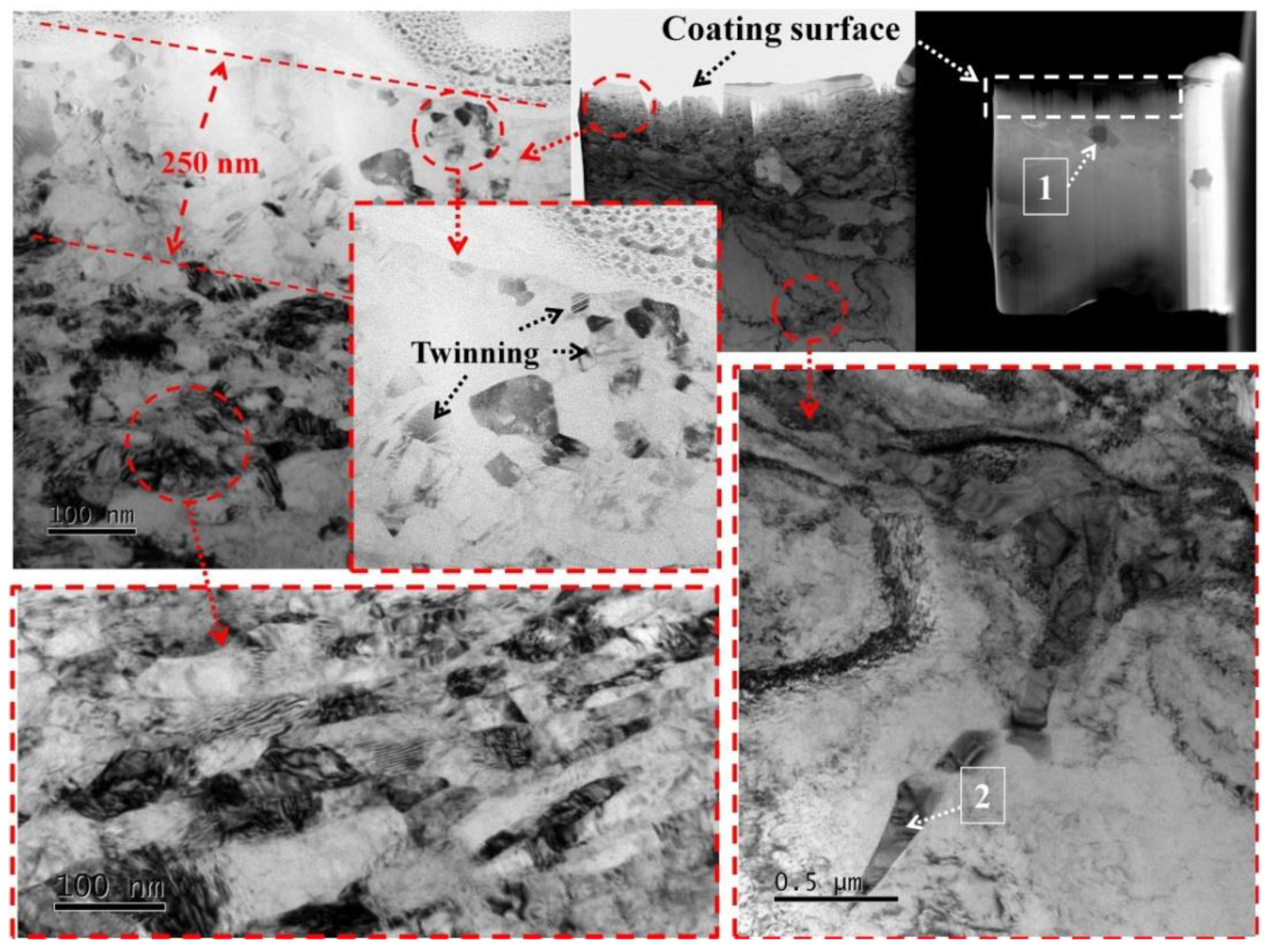
From the DSA-TEM analysis results shown in Figure 10, it can be seen that the morphology of the (Ti, Nb)(C, B)/IN625 composite coating in the whole wear region presents three distinctive features from top to bottom, which are the equiaxed ultra-fine crystalline region in the range of 0-250 nm, the deformed region of fine grains in the range of 250-800 nm, and the original (Ti, Nb)(C, B)/IN625 composite coating zone at a depth of 800 nm and above. Because of influences of the axial loading force and thermal accumulation during the wear testing [27], the grain refining process, which is different from the original coating organization, occurs in the range of 800 nm under the superficial zone of the coating, and the refining grains formed during this process are mostly flattened in shape and have a certain directionality. This process was mainly related to the thermal-force coupling during the wear testing, which further led to the dynamic recrystallization [28] combined with the dynamic plastic deformation [29] of the original grains at this position. According to the principle of dynamic recrystallization [30], it is known that dislocations within the low-level fault-energy material can be made to re-nucleate and re-grow grains at the original grain boundary by slipping/climbing, which in turn eliminates the dislocations and deformation defects, such as sub-grain boundaries in deformed substrate. It is further observed that the ultra-fine equiaxed crystals in the range of 250 nm, with the grain sizes of 10-50 nm, are formed due to the fact that the Ti(C, B) particles synthesized by the in-situ reaction play the key roles of abrasion reduction and regional supporting towards the IN625 substrate, and the abrasion plowing of the SiC sandpaper on the coating substrate IN625 will be significantly reduced (the depth of abrasion plowing shown in Figure 9a is significantly smaller than that shown in Figure 9b), which on the contrary promotes the continuous thermoplastic deformation of the wear surface. Finally, under the coupling of plastic-thermal-force fields by strong surface friction, the super-plastic deformation is promoted to occur in the wear surface zone within the depth of 250 nm, and then the microstructures of equiaxed ultra-fine crystal are obtained. It is important to note that the presence of a large number of twinning inside the ultra-fined equiaxed grains confirms the existence of superplastic deformation in the wear surface region under a depth of 250 nm, and the characteristic of wear morphology in Figure 9a shows the local adhesive wear as well.
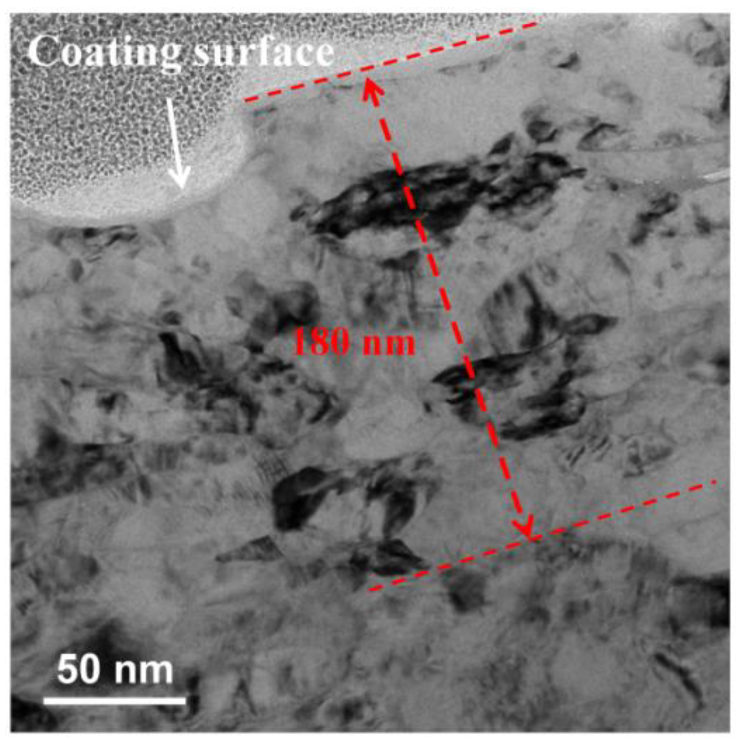
However, the wear surface of IN625 coating prepared by EHLA has no obvious ultra-refined equiaxed grains, but deformed grains in the range of 0-180 nm instead. Since there is no supporting effect of hard particle phases in the wear surface area of IN625 coating, the grains near the wear surface could not be refined before being quickly ploughed away by SiC sandpaper during the wear testing process. Therefore, only the plastic deformation in the superficial wear region of IN625 coating is observed clearly as shown in Figure 11.
The surface Vickers hardness of the (Ti, Nb)(C, B)/IN625 composite coating is lower than that of the IN625 coating. It is analyzed that, on the one hand, due to the relatively small particle size and density of B4C in the original mixed powder, some losses of B4C are inevitable in the process of powder feeding during the EHLA, which in turn causes the relatively high content of Ti in the mixed powder into the laser melting pool and promotes the other in-situ reaction with the C in the composition of IN625 to generate TiC, thereby reducing the hardness of the IN625 substrate; on the other hand, it is also demonstrated by the interfacial stress distribution characteristics of the (Ti, Nb)(C, B)/IN625 composite coating shown in Figure 8 that the Joule heat released from the Eq. 1 reaction has retarded the rate of cooling down during the EHLA process, which plays as another role in the reduction of the hardness. But it is interesting to note that the reduction in hardness of the (Ti, Nb)(C, B)/IN625 composite coating has in fact resulted in lower friction coefficient and wear rate, where the values of the former and the latter are about 50% and 10%, respectively, of those of the IN625 coating. Meanwhile, the lower friction coefficient plays a role of wear reduction and wear resistance for (Ti, Nb)(C, B)/IN625 composite coating, which is mainly attributed to the high hardness of the in-situ synthesized (Ti, Nb)(C, B) particle phases, as well as the good wettability with the IN625 substrate, which makes it not easy for the (Ti, Nb)(C, B) particle phases to be detached from the substrate [31], and acts as a significant wear reducing and supporting effect on the IN625 substrate.
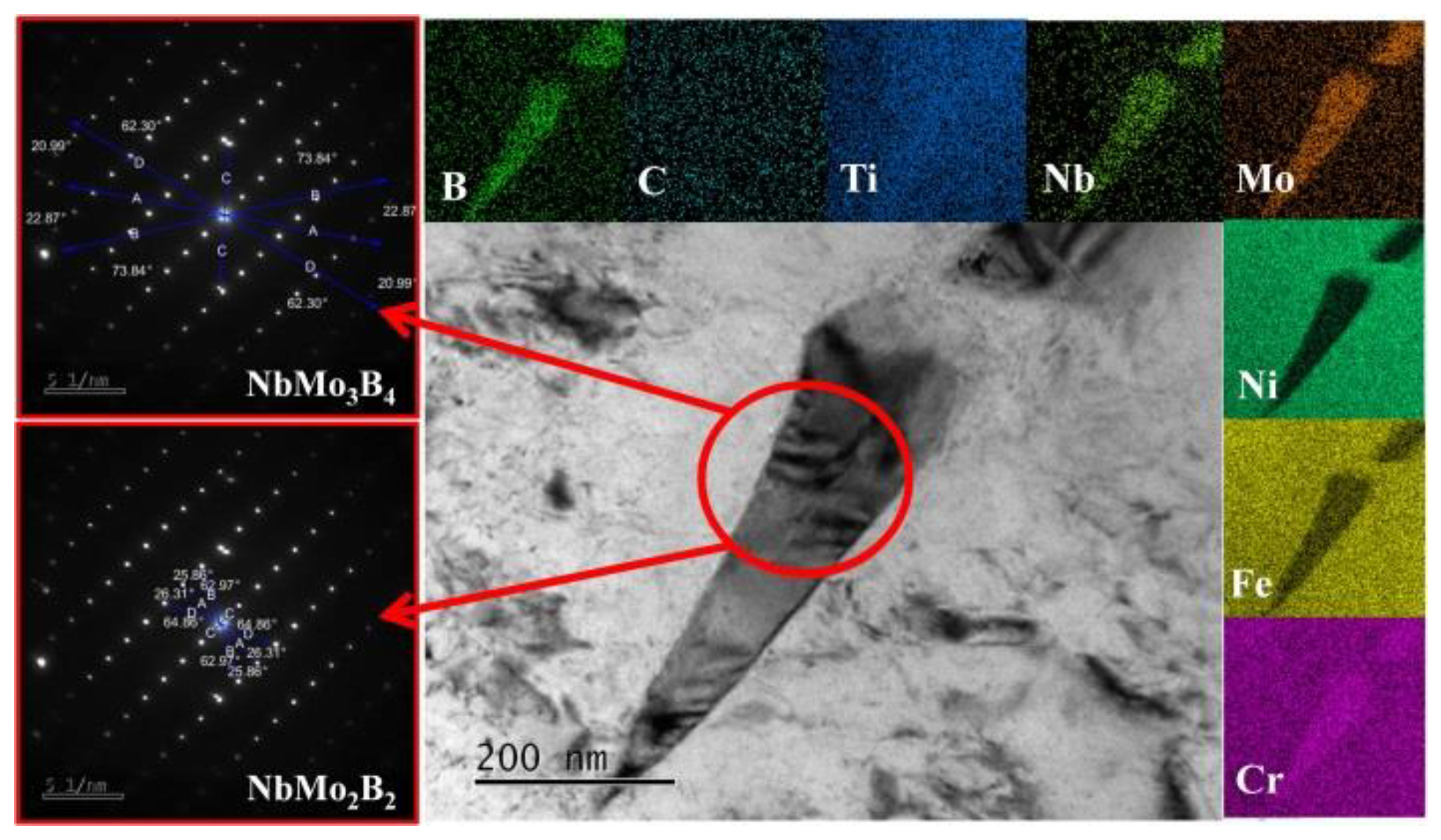
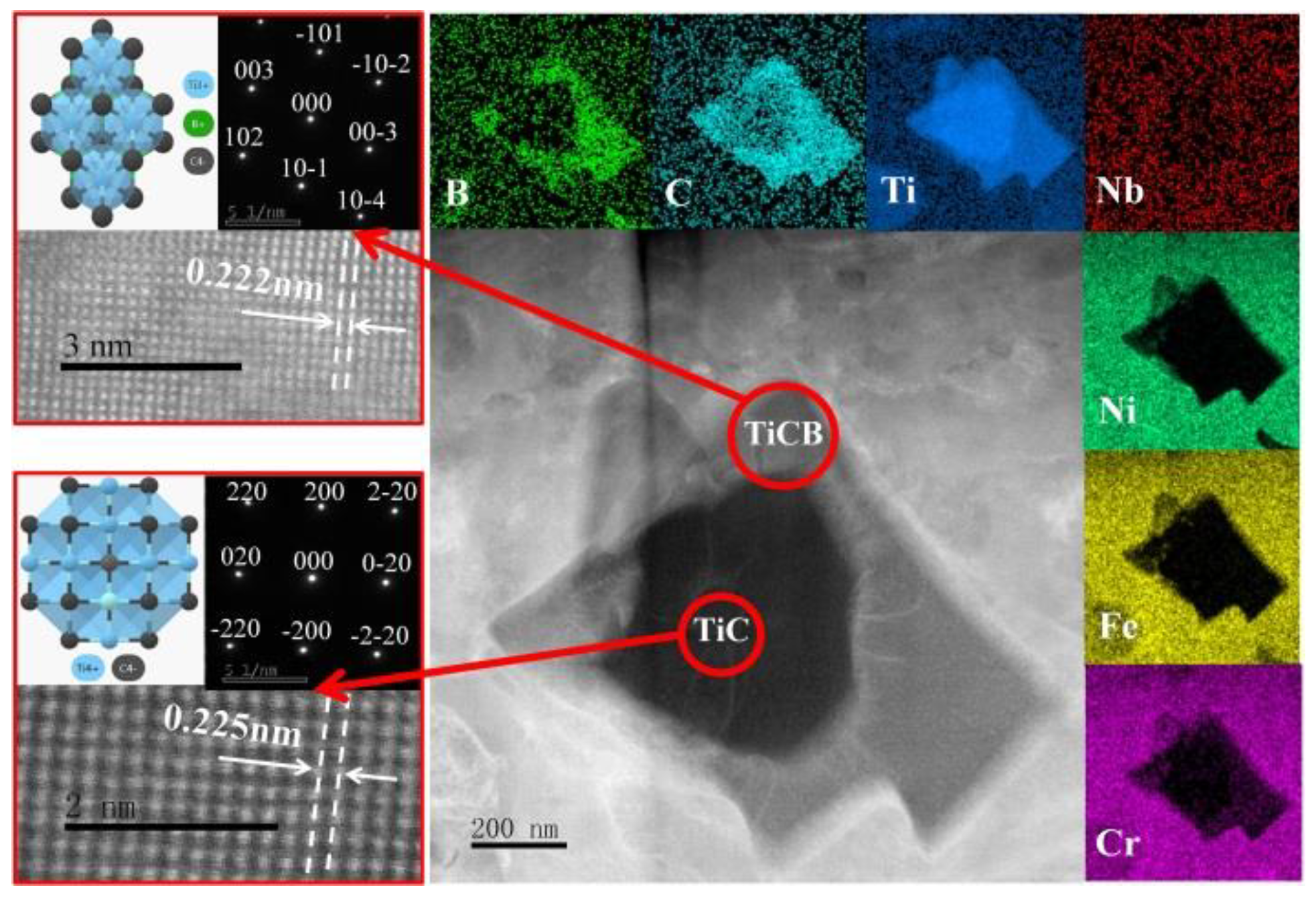
The EDS analysis and electron diffraction analysis are carried out on the precipitated phase No.1 shown in Figure 10. The composite precipitated phase is identified as TiC-TiCB shown in Figure 12, with atomic spacings of 0.225 nm and 0.222 nm, respectively. The stabilized TiC-TiB2 composite precipitated phases described in the previous work [20] is not detected from the analyzed results, which is due to the fact that the extra-ordinary cooling rate of the EHLA process is not enough to provide the thermodynamic conditions for the TiC-TiB2 phases from billet, nucleation to final growth. Therefore, the existence of unstable phase during the EHLA process is inevitable [14]. According to the EDS analysis results, the composite precipitated phase is Ti-rich internally and C-B-rich externally, which basically conforms to the evolutionary trend of generating Ti-C phase in priority and coupling Ti-B phase in following.
In addition, EDS analysis and electron diffraction analysis are undertaken for the needle-like phase No.2 shown in Figure 10. The phase presents an intergranular distribution, and the precipitated positions are consistent with the blue-marked phases as shown in Figure 6b. It is determined by diffraction pattern analysis that the phase consists of unstable NbMo3B4 and unstable NbMo2B2, which have a parallel phase relationship of [001]NbMo2B2∥[-403]NbMo3B4 . The formation of those unstable phases is not related to the lack of stable thermodynamic conditions above mentioned for EHLA, but to the presence of strong boride precipitating element Nb and weak boride precipitating element Mo in the IN625 substrate. By the transient melting pool metallurgy, the residual B is combined with Nb and Mo in a short time, and finally the unstable Nb-Mo-B composite precipitation phases are formed and mostly existed at grain boundaries, which plays an auxiliary role in restraining the wearing process of the coating.
Figure 13. The EDS analysis and electron diffraction analysis of phase No.2 at the position shown in Figure10.
Preprints 90707 g013

5. Conclusions

(1) The (Ti, Nb)(C, B)/IN625 composite coating was successfully prepared by EHLA via introducing the in-situ exothermic reaction. The interfacial width of the coating was up to 24 μm, which was 6 times of that of the N625 coating by EHLA process, effectively improving the dilution rate during the cladding process. The composite coating was mainly composed of columnar grains and in-situ phases, where the latter contained TiCB, TiC, NbMo3B4 and NbMo2B2.
(2) A modified method based on the AFM measurement of residual indent and contact mechanics was proposed to measurement the residual stresses in this paper and compared with the G&S energy method commonly used in the literature. Good agreement was found between the G&S energy method and our method, suggesting using the G&S energy method would be adequate for fast residual stress measurement in the chosen material system without the need of AFM direct measurements. In comparison to the steep drop of residual stresses near the interface of the IN625 coating prepared by EHLA, the sudden change of residual stresses at the interface position of the (Ti, Nb)(C, B)/IN625 composite coating was alleviated with the assistance of the in-situ exothermic reaction.
(3) Because of the existence of the in-situ particle phases and their supporting effect on the IN625 substrate, the (Ti, Nb)(C, B)/IN625 composite coating has outstanding properties of wear reduction and abrasion resistance, resulting in the average friction coefficient and the average coating wear rate being 0.1506 and 0.012 g/h, which are about 50% and 10% of those of the IN625 coating prepared by the EHLA, respectively.

CRediT authorship contribution statement

Carried out the experiments, performed the data analyses and wrote the manuscript: Nan Zhang, Borui Du. Helped perform the analysis with constructive discussions: Shaoping Chen, Yifei Xu, Hua Shi. Helped to polish, revise the manuscript, provide the conception of this study and conduct the experiment instruction: Miaohui Wang.

Declaration of Competing Interest

The authors declare that they have no known competing financial interests or personal relationships that could have appeared to influence the work reported in this paper.

Data Availability

No data was used for the research described in the article.

Acknowledgements

This work was financially supported by National Key Research and Development Program (No. 2021YFB3702003), from China, National Natural Science Foundation of China (No. 51975240), from China, Beijing Natural Science Foundation (No. 2222093), from China. Finally, thinks to eceshi (www.eceshi. com) for the nanoindentation testing and Jinan Yihua Tribology Testing Institute for wear testing.

Conflict of Interest Statement

This is a manuscript entitled “(Ti, Nb)(C, B)/IN625 in-situ reactive coating prepared by ultra-high speed laser cladding: Interfacial characterization, residual stress and surface wear mechanisms”. All authors certify that they have no affiliations with or involvement in any organization or entity with any financial interest or non-financial interest in the subject matter or materials discussed in this manu-script. The authors have no financial or proprietary interests in any material discussed in this article. The contents of this manuscript have not been copyrighted or published previously. The contents of this manuscript are not now under consideration for publication elsewhere. Authors are responsible for correctness of the statements provided in the manuscript.

References

  1. Schopphoven T, Gasser A, Wissenbach K, et al. Investigations on ultra-high-speed laser material deposition as alternative for hard chrome plating and thermal spraying[J]. Journal of Laser Applications, 2016, 28(2): 022501. [CrossRef]
  2. Lampa C, Smirnov I. High speed laser cladding of an iron based alloy developed for hard chrome replacement [J]. Journal of Laser Applications, 2019, 31(2): 022511. [CrossRef]
  3. Raykia O. Alternative with a future: High-speed laser metal deposition replaces hard chrome plating[J]. Laser Technik Journal, 2017, 14(1): 28-30. [CrossRef]
  4. Shen B W, Du B R, Wang M H, et al. Comparison on microstructure and properties of stainless steel layer formed by extreme high-speed and conventional laser melting deposition [J], Frontiers in Materials, 2019, 6: 248-256. [CrossRef]
  5. Schopphoven T, Gasser A, Backes G. EHLA: extreme high speed laser material deposition[J]. Laser Technik Journal, 2017, 14(4): 26-29. [CrossRef]
  6. LI Zhaohui, LI Meiyan, HAN Bin, et al. High-pressure plunger high-speed laser cladding nickel-based alloy coating structure and wear resistance[J]. Surface technology, 2020, 49(10): 45-54. (in Chinese).
  7. Guo Y M, Ye F X, Qi H, et al. Research Status and Development of Ultra-high Speed Laser Cladding[J]. China Surface Engineering, 2022, 35(06): 39-50. (in Chinese).
  8. Yuan W Y, Li R F, Chen Z H, et al. A comparative study on microstructure and properties of traditional laser cladding and high-speed laser cladding of Ni45 alloy coatings[J]. Surface and Coatings Technology, 2020, 405: 126582. [CrossRef]
  9. Asghar O, Lou L Y, Yasir M, et al. Enhanced tribological properties of LA43M magnesium alloy by Ni60 coating via ultra-high-speed laser cladding[J]. Coatings, 2020, 10: 638-651. [CrossRef]
  10. Dong H, Han Y, Fu A Q, et al. Microstructure and corrosion resistance of Ni/stainless steel surfacing layer deposited via high-speed laser cladding[J]. Surface Technology, 2019, 48(5): 21-27. (in Chinese).
  11. Qiao Y X, Huang J, Huang D, et al. Effects of laser scanning speed on microstructure, microhardness, and corrosion behavior of laser cladding Ni45 coatings[J]. Journal of Chemistry, 2020, 10: 1438473. [CrossRef]
  12. Yang J X, Bai B, Ke H, et al. Effect of metallurgical behavior on microstructure and properties of FeCrMoMn coatings prepared by high-speed laser cladding[J]. Optics and Laser Technology, 2021, 144: 107431. [CrossRef]
  13. Zhang N. Study on the Microstructure and Properties of Functionally Gradient Materials Prepared by FAPACS [D]. Taiyuan university of Technology, 2020. (in Chinese).
  14. Zhang N, Xu Y F, Wang M H, et al. M2 coating prepared by ultra-high speed laser cladding: Microstructure and interfacial residual stress[J]. Materials Today Communications, 2023, 35: 105638. [CrossRef]
  15. Eddine B S, Mokhtar B, Ali D. Influences of TiC Impurities on Dry-sliding Wear of polycrystalline Ceramic[J]. Journal of Wuhan University of Technology(Materials Science), 2022, 37(04): 570-575. [CrossRef]
  16. Fan J Z, Shen W X, Zhang Z F, et al. Properties of B4C-TiB2 ceramics prepared by spark plasma sintering[J]. Chinese Physics B, 2021, 30(03): 579-584. [CrossRef]
  17. Chen L, Sun Y Z, Li L, et al. Improvement of high temperature oxidation resistance of additively manufactured TiC/Inconel 625 nanocomposites by laser shock peening treatment[J]. Additive Manufacturing, 2020, 34: 101276. [CrossRef]
  18. Chen L, Zhang X Z, Wu Y, et al. Effect of surface morphology and microstructure on the hot corrosion behavior of TiC/IN625 coatings prepared by extreme high-speed laser cladding[J]. Corrosion Science, 2022, 201: 110271. [CrossRef]
  19. Ge T. Microstructure and Properties of TiC/IN625 Composite Coatings by Extreme High Speed Laser Cladding [D]. Jiangsu university, 2022. (in Chinese).
  20. Zhang N, Meng Q S, Chen S P, et al. TiC-TiB2-Ni/TiAl/Ti gradient functionally materials synthesized by in-situ synthesis via field-activated and pressure-assisted synthesis [J]. Journal of Functional Materials, 2010, 41(09): 1497-1500. (in Chinese).
  21. Zhang E L, Yang B, Zeng S Y, et al. Formation mechanism of TiC in Al/TiC composites prepared by direct reaction synthesis[J]. Transactions of Nonferrous Metals Society of China, 1998, 8(1): 92-96.
  22. Zhu L N, Xu B S, Wang H D, et al. Determination of hardness of plasma-sprayed FeCrBSi coating on steel substrate by nanoindentation[J]. Materials Science and Engineering: A, 2010, 528(1): 425–428. [CrossRef]
  23. Lee Y H, Kwon D. Measurement of residual-stress effect by nanoindentatio on elastically strained (100) W [J]. Scripta Materialia, 2003, 49: 459-465. [CrossRef]
  24. Munir Z A, Anselmi-Tamburini U. The effect of electric field and pressure on the synthesis and consolidation of materials: A review of the spark plasma sintering method [J]. Journal of Mateirals Scinece, 2006, 41: 763-777. [CrossRef]
  25. Chen S P. Diffusion bonding mechanism and properties of the joints between gradient cermets and metals bonding by the FAPAS process [D]. Taiyuan university of technology, 2010. (in Chinese).
  26. Li L Q, Shen F M, Zhou Y D, et al. Comparative study of stainless steel AISI 431 coatings prepared by extreme-high-speed and conventional laser cladding[J]. Journal of Laser Applications, 2019, 31: 042009. [CrossRef]
  27. Zhou J L, Shen F, Liu J, et al. Thermoelastic rotating contact of an FGM coating with temperature-dependent and arbitrary varying properties[J]. Science China Technological Sciences, 2023, 66(04): 1038. [CrossRef]
  28. Aziz S B, Dewan M W, Huggett D J, et al. Impact of Friction Stir Welding (FSW) Process Parameters on Thermal Modeling and Heat Generation of Aluminum Alloy Joints[J]. Acta Metallurgica Sinica (English Letters), 2016, 29(09): 869. [CrossRef]
  29. Zuo L, Zhao X, Li Z, et al. A review of friction stir joining of SiCp/Al composites[J]. Chin. J. Aero., 2020, 33(03): 792. [CrossRef]
  30. Hu G X, Cai X, Rong Y H. Fundamental Materials Science (3rd Edition) [M]. Shanghai: Shanghai Jiao Tong University Press, 2010: 213.
  31. Chen S P, Meng Q S, Munir Z A. Graded Materials of (TiB2)pNi with Nickel Substrate Prepared by Field-Activated Pressure-Assisted Synthesis Process[J]. J. Wuhan University. of Technology. (Mater. Sci. Ed.), 2010, 25(01): 39-43. [CrossRef]
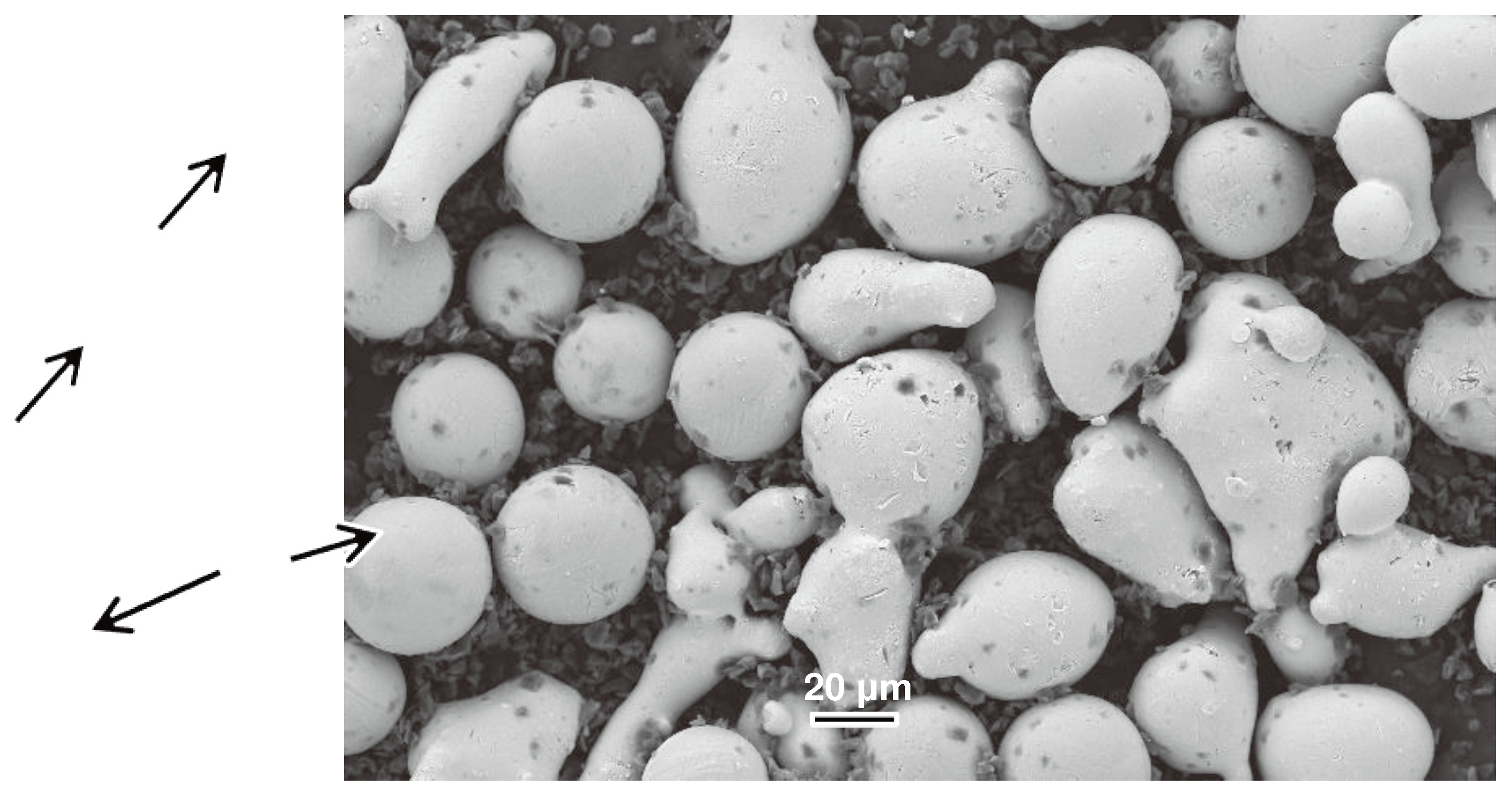
Figure 1. Pre-alloyed powder morphologies.
Preprints 90707 g001
Figure 4. Deformation height hpi (i=1, 2, 3) and width xi (i=1, 2, 3) of residual indent edges.
Preprints 90707 g004
Figure 6. Morphologies of (Ti,Nb)(C,B)/IN625 composite coating: columnar crystals with BSD (a), equiaxial crystals with EBSD (b) and their KAM map (c).
Preprints 90707 g006
Figure 7. Indentation load-displacement curves obtained from stressed sample and stress-free sample #1.
Preprints 90707 g007
Figure 8. Residual stress distribution on the cross section of coating by ultra-high speed laser cladding.
Preprints 90707 g008
Figure 9. Surface wear morphologies of (Ti, Nb)(C, B)/IN625 composite coating (a) and IN625 coating (b).
Preprints 90707 g009
Figure 10. DSA-TEM images of (Ti, Nb)(C, B)/IN625 composite coating based on fabricated FIB sample.
Preprints 90707 g010
Figure 11. DSA-TEM image of IN625 coating prepared by EHLA.
Preprints 90707 g011
Figure 12. The EDS analysis and electron diffraction analysis of phase No.1 at the position shown in Figure10.
Preprints 90707 g012
Disclaimer/Publisher’s Note: The statements, opinions and data contained in all publications are solely those of the individual author(s) and contributor(s) and not of MDPI and/or the editor(s). MDPI and/or the editor(s) disclaim responsibility for any injury to people or property resulting from any ideas, methods, instructions or products referred to in the content.
Copyright: This open access article is published under a Creative Commons CC BY 4.0 license, which permit the free download, distribution, and reuse, provided that the author and preprint are cited in any reuse.
Prerpints.org logo

Preprints.org is a free preprint server supported by MDPI in Basel, Switzerland.

Subscribe

© 2024 MDPI (Basel, Switzerland) unless otherwise stated