Submitted:
17 November 2023
Posted:
22 November 2023
You are already at the latest version
Abstract
Keywords:
1. Introduction
2. Experimental Section
2.1. Chemicals and Materials
2.2. Preparation of AgNWs
2.3. Preparation of ANFs/DMSO Solution
2.4. Preparation of NAAANF Films
2.5. Characterizations
3. Results and Discussion
3.1. Morphologies and Microstructures of ANFs and AgNWs
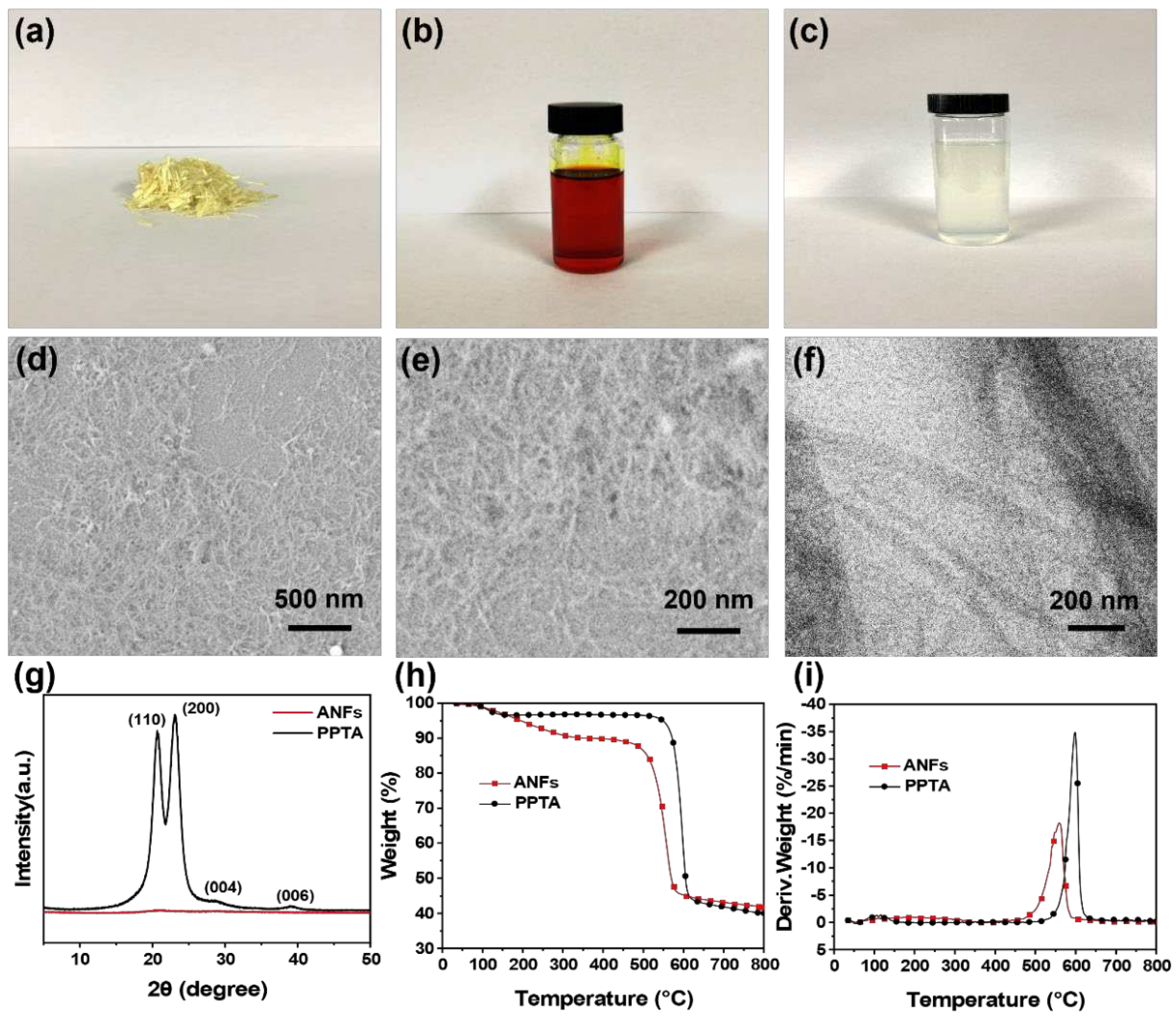
| Sample | T-5wt% (°C) | Tmax (°C) | Residue at 800 °C (wt %) |
|---|---|---|---|
| ANF | 195 | 560 | 40.6 |
| PPTA | 548 | 598 | 39.7 |
3.2. Structurale Characterization of NAAANF
3.3. Electrical Conductivity and EMI shielding Properties of NAAANF
3.4. Mechanical Properties and Thermal Stability of NAAANF
4. Conclusions
Acknowledgments
References
- Xie, Y.; Liu, S.; Huang, K.; Chen, B.; Shi, P.; Chen, Z.; Liu, B.; Liu, K.; Wu, Z.; Chen, K.; et al. Ultra-Broadband Strong Electromagnetic Interference Shielding with Ferromagnetic Graphene Quartz Fabric. Adv. Mater. 2022, 34, 2202982. [Google Scholar] [CrossRef] [PubMed]
- Rebecchi, F.; Pastor, A.; Mozo, A.; Lombardo, C.; Bruschi, R.; Aliferis, I.; Doriguzzi-Corin, R.; Gouvas, P.; Alvarez Romero, A.; Angelogianni, A.; et al. A Digital Twin for the 5G Era: The SPIDER Cyber Range. 2022 IEEE 23rd Int. Symp. a World Wireless, Mob. Multimed. Networks, 2022. [Google Scholar] [CrossRef]
- Wang, J.; Wu, X.; Wang, Y.; Zhao, W.; Zhao, Y.; Zhou, M.; Wu, Y.; Ji, G. Green, Sustainable Architectural Bamboo with High Light Transmission and Excellent Electromagnetic Shielding as a Candidate for Energy-Saving Buildings. Nano-Micro Lett. 2023, 15, 1–16. [Google Scholar] [CrossRef]
- Zhang, Y.; Cheng, W.; Tian, W.; Lu, J.; Song, L.; Liew, K.M.; Wang, B.; Hu, Y. Nacre-Inspired Tunable Electromagnetic Interference Shielding Sandwich Films with Superior Mechanical and Fire-Resistant Protective Performance. ACS Appl. Mater. Interfaces 2020, 12, 6371–6382. [Google Scholar] [CrossRef]
- Li, Y.; Shang, Y.; Li, M.; Zhang, X.; He, J. High Electromagnetic Shielding Effect of Carbon Nanotubes/Waterborne Polyurethane Composites Prepared by “Break-Adsorption” Method. Mater. 2022, Vol. 15, Page 6430 2022, 15, 6430. [Google Scholar] [CrossRef]
- Abbasi, H.; Antunes, M.; Velasco, J.I. Recent Advances in Carbon-Based Polymer Nanocomposites for Electromagnetic Interference Shielding. Prog. Mater. Sci. 2019, 103, 319–373. [Google Scholar] [CrossRef]
- Shahzad, F.; Alhabeb, M.; Hatter, C.B.; Anasori, B.; Hong, S.M.; Koo, C.M.; Gogotsi, Y. Electromagnetic Interference Shielding with 2D Transition Metal Carbides (MXenes). Science (80-. ). 2016, 353, 1137–1140. [Google Scholar] [CrossRef] [PubMed]
- Cao, C.F.; Yu, B.; Chen, Z.Y.; Qu, Y.X.; Li, Y.T.; Shi, Y.Q.; Ma, Z.W.; Sun, F.N.; Pan, Q.H.; Tang, L.C.; et al. Fire Intumescent, High-Temperature Resistant, Mechanically Flexible Graphene Oxide Network for Exceptional Fire Shielding and Ultra-Fast Fire Warning. Nano-Micro Lett. 2022, 14, 1–18. [Google Scholar] [CrossRef] [PubMed]
- Yin, Z.; Lu, J.; Hong, N.; Cheng, W.; Jia, P.; Wang, H.; Hu, W.; Wang, B.; Song, L.; Hu, Y. Functionalizing Ti3C2Tx for Enhancing Fire Resistance and Reducing Toxic Gases of Flexible Polyurethane Foam Composites with Reinforced Mechanical Properties. J. Colloid Interface Sci. 2022, 607, 1300–1312. [Google Scholar] [CrossRef] [PubMed]
- Qiu, S.; Zhou, Y.; Zhou, X.; Zhang, T.; Wang, C.; K Yuen, R.K.; Hu, W.; Hu, Y.; Qiu, S.; Zhou, Y.; et al. Air-Stable Polyphosphazene-Functionalized Few-Layer Black Phosphorene for Flame Retardancy of Epoxy Resins. Small 2019, 15, 1805175. [Google Scholar] [CrossRef]
- Xiong, J.; Ding, R.; Liu, Z.; Zheng, H.; Li, P.; Chen, Z.; Yan, Q.; Zhao, X.; Xue, F.; Peng, Q.; et al. High-Strength, Super-Tough, and Durable Nacre-Inspired MXene/Heterocyclic Aramid Nanocomposite Films for Electromagnetic Interference Shielding and Thermal Management. Chem. Eng. J. 2023, 474, 145972. [Google Scholar] [CrossRef]
- Zazoum, B.; Bachri, A.; Nayfeh, J. Functional 2D MXene Inks for Wearable Electronics. Mater. 2021, Vol. 14, Page 6603 2021, 14, 6603. [Google Scholar] [CrossRef] [PubMed]
- Pušić, T.; Šaravanja, B.; Malarić, K. Electromagnetic Shielding Properties of Knitted Fabric Made from Polyamide Threads Coated with Silver. Mater. 2021, Vol. 14, Page 1281 2021, 14, 1281. [Google Scholar] [CrossRef] [PubMed]
- Liu, H.; Huang, J.; Guo, B.; Liu, H.; Huang, J.; Guo, B. Light Weight, Flexible and Ultrathin PTFE@Ag and Ni@PVDF Composite Film for High-Efficient Electromagnetic Interference Shielding. Mater. 2023, Vol. 16, Page 4831 2023, 16, 4831. [Google Scholar] [CrossRef] [PubMed]
- Cheng, M.; Ying, M.; Zhao, R.; Ji, L.; Li, H.; Liu, X.; Zhang, J.; Li, Y.; Dong, X.; Zhang, X. Transparent and Flexible Electromagnetic Interference Shielding Materials by Constructing Sandwich AgNW@MXene/Wood Composites. ACS Nano 2022, 16, 16996–17007. [Google Scholar] [CrossRef] [PubMed]
- Fu, C.; Sheng, Z.; Zhang, X. Laminated Structural Engineering Strategy toward Carbon Nanotube-Based Aerogel Films. 2022, 16, 9378-9388. [CrossRef]
- Yu, J.; Cui, Z.; Lu, J.; Zhao, J.; Zhang, Y.; Fan, G.; Liu, S.; He, Y.; Yu, Y.; Qi, D. Integrated Hierarchical Macrostructures of Flexible Basalt Fiber Composites with Tunable Electromagnetic Interference (EMI) Shielding and Rapid Electrothermal Response. Compos. Part B Eng. 2021, 224, 109193. [Google Scholar] [CrossRef]
- Tretjak, M.; Pralgauskaitė, S.; Matukas, J.; Plyushch, A.; Macutkevič, J.; Banys, J.; Karakashov, B.; Fierro, V.; Celzard, A. Electrical Resistivity and Microwave Properties of Carbon Fiber Felt Composites. Mater. 2022, Vol. 15, Page 8654 2022, 15, 8654. [Google Scholar] [CrossRef] [PubMed]
- Yu, B.; Yuen, A.C.Y.; Xu, X.; Zhang, Z.C.; Yang, W.; Lu, H.; Fei, B.; Yeoh, G.H.; Song, P.; Wang, H. Engineering MXene Surface with POSS for Reducing Fire Hazards of Polystyrene with Enhanced Thermal Stability. J. Hazard. Mater. 2021, 401, 123342. [Google Scholar] [CrossRef] [PubMed]
- Jia, F.; Dong, J.; Dai, X.; Liu, Y.; Wang, H.; Lu, Z. Journal Pre-Proofs Robust, Flexible, and Stable CuNWs/MXene/ANFs Hybrid Film Constructed by Structural Assemble Strategy for Efficient EMI Shielding Robust, Flexible, and Stable CuNWs/MXene/ANFs Hybrid Film Constructed by Structural Assemble Strategy For. Chem. Eng. J. 2022, 452, 139395. [Google Scholar] [CrossRef]
- Wang, H.; Zhuang, T.; Wang, J.; Sun, X.; Wang, Y.; Li, K.; Dai, X.; Guo, Q.; Li, X.; Chong, D.; et al. Multifunctional Filler-Free PEDOT:PSS Hydrogels with Ultrahigh Electrical Conductivity Induced by Lewis-Acid-Promoted Ion Exchange. Adv. Mater. 2023, 2302919. [Google Scholar] [CrossRef]
- Li, Y.; Xue, B.; Yang, S.; Cheng, Z.; Xie, L.; Zheng, Q. Flexible Multilayered Films Consisting of Alternating Nanofibrillated Cellulose/Fe3O4 and Carbon Nanotube/Polyethylene Oxide Layers for Electromagnetic Interference Shielding. Chem. Eng. J. 2021, 410, 128356. [Google Scholar] [CrossRef]
- Gong, S.; Sheng, X.; Li, X.; Sheng, M.; Wu, H.; Lu, X.; Qu, J. A Multifunctional Flexible Composite Film with Excellent Multi-Source Driven Thermal Management, Electromagnetic Interference Shielding, and Fire Safety Performance, Inspired by a “Brick–Mortar” Sandwich Structure. Adv. Funct. Mater. 2022, 32, 2200570. [Google Scholar] [CrossRef]
- Yao, J.; Zhang, L.; Yang, F.; Jiao, Z.; Tao, X.; Yao, Z.; Zheng, Y.; Zhou, J. Superhydrophobic Ti3C2Tx MXene/Aramid Nanofiber Films for High-Performance Electromagnetic Interference Shielding in Thermal Environment. Chem. Eng. J. 2022, 446, 136945. [Google Scholar] [CrossRef]
- Yang, B.; Wang, L.; Zhang, M.; Luo, J.; Lu, Z.; Ding, X.; Yang, B.; Wang, L.; Zhang, M.; Luo, J.; et al. Fabrication, Applications, and Prospects of Aramid Nanofiber. Adv. Funct. Mater. 2020, 30, 2000186. [Google Scholar] [CrossRef]
- Lee, J.U.; Park, B.; Kim, B.S.; Bae, D.R.; Lee, W. Electrophoretic Deposition of Aramid Nanofibers on Carbon Fibers for Highly Enhanced Interfacial Adhesion at Low Content. Compos. Part A Appl. Sci. Manuf. 2016, 84, 482–489. [Google Scholar] [CrossRef]
- Yang, Y.; Huang, C.; Gao, G.; Hu, C.; Luo, L.; Xu, J. Aramid Nanofiber/Bacterial Cellulose Composite Separators for Lithium-Ion Batteries. Carbohydr. Polym. 2020, 247, 116702. [Google Scholar] [CrossRef] [PubMed]
- Zhao, B.; Ma, Z.; Sun, Y.; Han, Y.; Gu, J. Flexible and Robust Ti3C2Tx /(ANF@FeNi) Composite Films with Outstanding Electromagnetic Interference Shielding and Electrothermal Conversion Performances. 2022, 3, 2200162. [CrossRef]
- 29. Yixin Han, Kunpeng Ruan, and J.G. Multifunctional Thermally Conductive Composite Films Based on Fungal Tree-like Heterostructured Silver Nanowires@Boron Nitride Nanosheets and Aramid Nanofibers. Small Struct. [CrossRef]
- Pan, X.-F.; Yu, G.-H.; Gao, H.-L.; Wang, Z.-Z.; Bao, Z.; Li, X.; Yu, S.-H.; Pan, X.; Yu, G.; Gao, H.; et al. Large-Scale Production of Rectorite Nanosheets and Their Co-Assembly with Aramid Nanofibres for High-Performance Electrical Insulating Nanopapers. Adv. Mater. 2022, 2206855. [Google Scholar] [CrossRef]
- Yang, B.; Wang, L.; Zhao, J.; Pang, R.; Yuan, B.; Tan, J.; Song, S.; Nie, J.; Zhang, M. A Robust, Flexible, Hydrophobic, and Multifunctional Pressure Sensor Based on an MXene/Aramid Nanofiber (ANF) Aerogel Film. ACS Appl. Mater. Interfaces 2022, 14, 47075–47088. [Google Scholar] [CrossRef] [PubMed]
- Li, L.; Yuan, X.; Zhai, H.; Zhang, Y.; Ma, L.; Wei, Q.; Xu, Y.; Wang, G. Flexible and Ultrathin Graphene/Aramid Nanofiber Carbonizing Films with Nacre-like Structures for Heat-Conducting Electromagnetic Wave Shielding/Absorption. ACS Appl. Mater. Interfaces 2023, 15, 15872–15883. [Google Scholar] [CrossRef]
- Hu, F.; Zeng, J.; Li, P.; Wang, T.; Li, J.; Wang, B.; Chen, K. Nacre-Inspired Strong Nanopapers of Aramid Nanofiber-Integrated Montmorillonite Nanoplates, Cellulose Nanofibrils, and Ag Nanowires for High-Performance Electrical Heaters. J. Mater. Chem. A. 2023, 11, 14126. [Google Scholar] [CrossRef]
- Hu, Y.; Yang, G.; Zhou, J.; Li, H.; Shi, L.; Xu, X.; Cheng, B.; Zhuang, X. Proton Donor-Regulated Mechanically Robust Aramid Nanofiber Aerogel Membranes for High-Temperature Thermal Insulation. ACS Nano 2022, 16, 5993. [Google Scholar] [CrossRef]
- Yin, Q.; Jia, H.; Liu, G.; Ji, Q.; Yin, Q.; Jia, H.; Liu, G.; Ji, Q. Tailoring the Mechanical Performance of Carbon Nanotubes Buckypaper by Aramid Nanofibers towards Robust and Compact Supercapacitor Electrode. Adv. Funct. Mater. 2022, 32, 2111177. [Google Scholar] [CrossRef]
- Huang, L.; Xiao, G.; Wang, Y.; Li, H.; Zhou, Y.; Jiang, L.; Wang, J. Self-Exfoliation of Flake Graphite for Bioinspired Compositing with Aramid Nanofiber toward Integration of Mechanical and Thermoconductive Properties. Nano-Micro Lett. 2022, 14, 1–13. [Google Scholar] [CrossRef] [PubMed]
- Wang, Z.G.; Jin, Y.F.; Hong, R.; Du, J.; Dai, K.; Zheng, G.Q.; Gao, J.; Xu, L.; Xu, J.Z.; Li, Z.M. Dual-Functional Thermal Management Materials for Highly Thermal Conduction and Effectively Heat Generation. Compos. Part B Eng. 2022, 242, 110084. [Google Scholar] [CrossRef]
- Wang, X.; Cao, W.; Su, Z.; Zhao, K.; Dai, B.; Gao, G.; Zhao, J.; Zhao, K.; Wang, Z.; Sun, T.; et al. Fabrication of High Thermal Conductivity Nanodiamond / Aramid Nanofiber Composite Films with Superior Multifunctional Properties. 2023. [CrossRef]
- Zhou, J.; Thaiboonrod, S.; Fang, J.; Cao, S.; Miao, M.; Feng, X. In-Situ Growth of Polypyrrole on Aramid Nanofibers for Electromagnetic Interference Shielding Films with High Stability. Nano Res. 2022, 15, 8536–8545. [Google Scholar] [CrossRef]
- Zeng, Z.; Chen, M.; Pei, Y.; Seyed Shahabadi, S.I.; Che, B.; Wang, P.; Lu, X. Ultralight and Flexible Polyurethane/Silver Nanowire Nanocomposites with Unidirectional Pores for Highly Effective Electromagnetic Shielding. ACS Appl. Mater. Interfaces 2017, 9, 32211–32219. [Google Scholar] [CrossRef] [PubMed]
- Zhang, Y.; Lu, J.; Yu, J.; Jiang, X.; Wang, Y.; Chen, X.; Zhang, H.; Yang, L.; Yu, Y.; Qi, D. Large Scale Fabrication of Recyclable and Multifunctional Sandwich-Structured Electromagnetic Interference Shielding Films Based on Waste Nylon-6 Silk. Mater. Today Phys. 2023, 36, 101177. [Google Scholar] [CrossRef]
- Chen, J.J.; Liu, S.L.; Wu, H. Bin; Sowade, E.; Baumann, R.R.; Wang, Y.; Gu, F.Q.; Liu, C.R.L.; Feng, Z.S. Structural Regulation of Silver Nanowires and Their Application in Flexible Electronic Thin Films. Mater. Des. 2018, 154, 266–274. [Google Scholar] [CrossRef]
- Ma, Z.; Kang, S.; Ma, J.; Shao, L.; Wei, A.; Liang, C.; Gu, J.; Yang, B.; Dong, D.; Wei, L.; et al. High-Performance and Rapid-Response Electrical Heaters Based on Ultraflexible, Heat-Resistant, and Mechanically Strong Aramid Nanofiber/Ag Nanowire Nanocomposite Papers. ACS Nano 2019, 13, 7578–7590. [Google Scholar] [CrossRef]
- Wang, Z.; Zhu, H.; Li, H.; Wang, Z.; Sun, M.; Yang, B.; Wang, Y.; Wang, L.; Xu, L. High-Strength Magnetic Hydrogels with Photoweldability Made by Stepwise Assembly of Magnetic-Nanoparticle-Integrated Aramid Nanofiber Composites. ACS Nano 2023, 17, 9622–9632. [Google Scholar] [CrossRef]
- Feng, L.; Wei, P.; Song, Q.; Zhang, J.; Fu, Q.; Jia, X.; Yang, J.; Shao, D.; Li, Y.; Wang, S.; et al. Superelastic, Highly Conductive, Superhydrophobic, and Powerful Electromagnetic Shielding Hybrid Aerogels Built from Orthogonal Graphene and Boron Nitride Nanoribbons. ACS Nano 2022, 16, 17049–17061. [Google Scholar] [CrossRef]
- Deng, Z.; Jiang, P.; Wang, Z.; Xu, L.; Yu, Z.Z.; Zhang, H. Bin Scalable Production of Catecholamine-Densified MXene Coatings for Electromagnetic Shielding and Infrared Stealth. Small 2023, 2304278. [Google Scholar] [CrossRef] [PubMed]
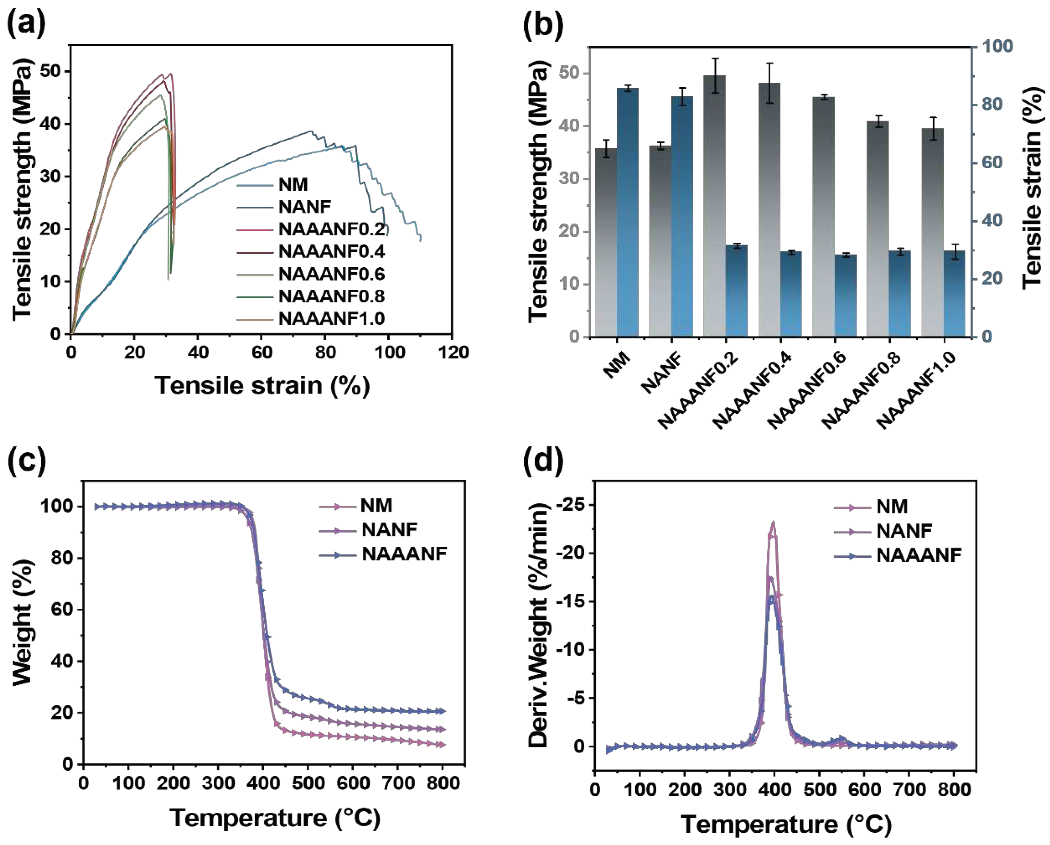
| Sample | T-5wt% (°C) | Tmax1 (°C) | Residue at 800 °C (wt %) |
|---|---|---|---|
| NM | 387.4 | 398.0 | 7.64 |
| NANF | 366.9 | 393.9 | 13.59 |
| NAAANF | 373.7 | 393.8 | 20.57 |
Disclaimer/Publisher’s Note: The statements, opinions and data contained in all publications are solely those of the individual author(s) and contributor(s) and not of MDPI and/or the editor(s). MDPI and/or the editor(s) disclaim responsibility for any injury to people or property resulting from any ideas, methods, instructions or products referred to in the content. |
© 2023 by the authors. Licensee MDPI, Basel, Switzerland. This article is an open access article distributed under the terms and conditions of the Creative Commons Attribution (CC BY) license (http://creativecommons.org/licenses/by/4.0/).


