1. Introduction
Vibration [
1,
2] is defined as a process during which a material body oscillates around its equilibrium position. Vibration [
3] is described by amplitude and phase at a given point in time. Since in real situations, a body cannot be described as a single point of mass, the oscillation through the body spreads gradually from one particle to another—this phenomenon is called waves. Waves can be classified as non-periodic and periodic. Periodic waves [
4] (harmonic vibrations) have a sinusoidal waveform and can be described by their speed, acceleration and deflection. These three quantities are the basis for the description and measurement of vibrations [
5]. We use speed mainly to determine the energy of vibrations, acceleration to determine the high-frequency components of vibrations, and deflection is used for low-frequency components.
The CSN ISO 10816 standard [
6] establishes the general rules for measuring and evaluating machine vibrations, and these vibrations are measured on non-rotating parts (especially on bearings). The standard [
6] stipulates that the measurement is generally broadband in order to cover the entire frequency range of a particular machine being measured. According to the standard [
6], the measured values are the vibration deflection, vibration velocity and vibration acceleration. In practice, the effective value of vibration velocity is mainly used for vibration evaluation due to its relationship with the energy of these vibrations. Two criteria are decisive for the assessment of vibration strength (the highest measured value from a set of vibrations performed at multiple locations and in multiple directions). The first is the magnitude of the vibration, and the second is the magnitude of the change in vibration [
7].
By vibrations [
8] we mean the mechanical oscillation of a body or elastic medium, where the individual points of the body/medium oscillate around an equilibrium position. The motion of the individual points of a body subjected to vibrations can be described by the time course of its deflection y(t) [m], velocity v(t) [m·s
–1] [
9] or acceleration a(t) [m·s
–2] (1).
The effective value of vibration acceleration a
RMS [m·s
–2] can be expressed as (2
).
In the article [
10], by the authors Perun and Opasiak, vibration measurements of the cylinder shell installed on a laboratory stand were made. It contains the results of the assessment of the technical condition of the rollers of belt conveyors after a specified period of operation.
Klimenda et al. [
11] deals with the measurement of noise and vibration of rollers for belt conveyors. In this article is described and individual rollers types which were measured. Process of noise and vibration measurement of the individual rollers types is given. Part of the article is noise and vibration measurement evaluation. Three the highest acceleration values in depending on the frequency of vibration in individual directions (
x, y, z) are given.
In the article [
12] Svoboda et al. deal with measuring vibrations on the stand of a roller conveyor. Difference between individual set of rollers is in used of semi-finished product of the outer shell, the design of the rollers is the same. One set has a shell from convectional tube and the second set from accuracy tube. The vibrations were measured by six-channel analyser Brüel & Kjær (PULSE). Acceleration and natural frequency were measured by using a three-axis accelerometer. In the conclusion of the article is an evaluation of vibration. Three the highest acceleration values in depending on the frequency of vibration in individual directions are given. From this evaluation are selected rollers with minimal and maximal acceleration.
In the article [
13] Bortnowski et al. created a device for a wireless measuring device that moves with the conveyor belt along of the route, which records the signal of transverse vibrations of the belt.
The roller is an important part of the belt conveyor in sand carrier at sea, presented by Peng et al in the article [
14]. They in this paper, a novel intelligent fault diagnosis method for rollers is proposed by using audio wavelet packet decomposition and Convolutional Neural Networks (CNN).
Article by M. Svoboda et al. [
15] deals with the measurement of vibrations on the stand of a roller conveyor. Acceleration and natural frequency were measured by using a three-axis accelerometer. In the conclusion of the article is an evaluation of vibration. Three the highest acceleration values in depending on the frequency of vibration in individual directions are given.
In many branches of industry, bulk materials are transported over short, medium and long transport distances using continuously working conveyor systems, the so-called belt conveyors [
16,
17,
18]. The conveyor belt, see
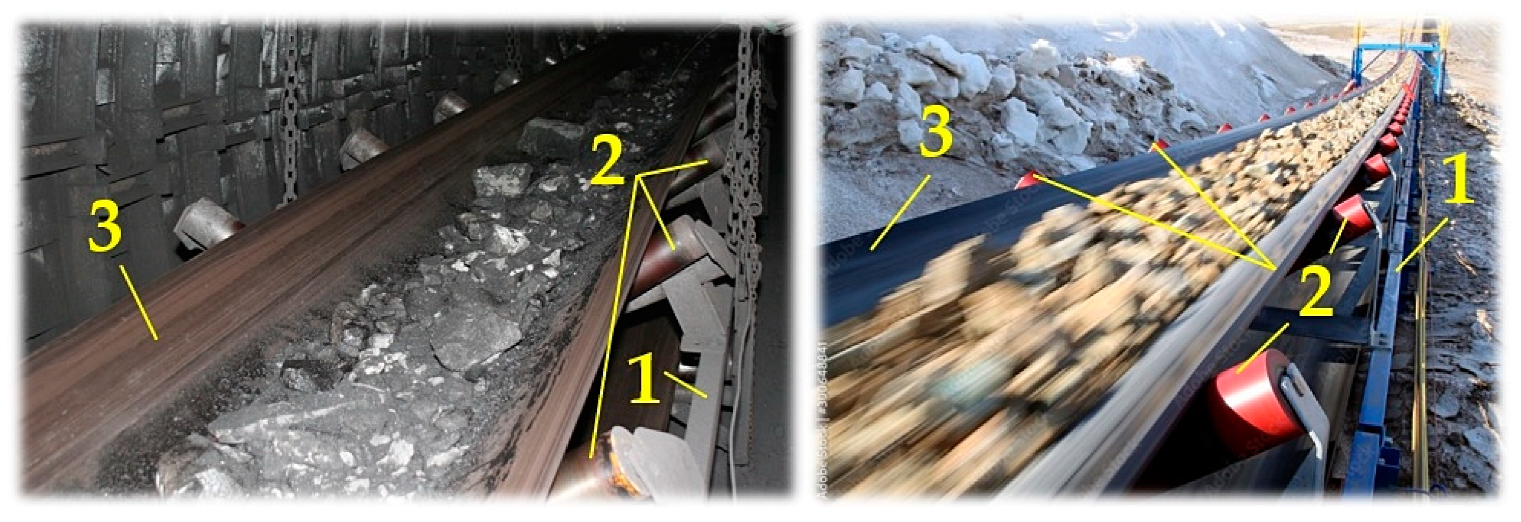
Figure 1, consists of a conveyor line
1 (assembled from steel assembled parts), which is fitted with conveyor rollers
2 [
19] that support the conveyor belt
3 [
20]. The endless loop of the conveyor belt circulates between two end drums. As a rule, on the upper surface of the conveyor belt, guided in the upper run of the belt conveyor [
21], the conveyed material is transported towards the driving station.
On the drive drum of a conveyor belt driving station, the conveyor belt is carried away by frictional forces acting on the contact surface between the surface of the drive drum casing and the surface of the conveyor belt. The solution of the force ratios acting on the driving drums is based on the basic Euler (Eytelwein) relation [
22,
23]. The transmission capability [
24,
25] between the drive drum and the conveyor belt depends on the angle of wrap, the coefficient of friction between the belt and the drive drum, and the belt tension (which generates the tension force of the conveyor belt).
Belt conveyor drives must be designed in such a way that the belt on the driving drums does not slip in the individual movement phases (start-up, steady running, and run-down phases). It is possible to increase the transmission capacity of belt conveyor drives by a number of technical measures, including e. g. increasing the coefficient of friction between the belt and the drive drum, increasing the preload of the conveyor belt and increasing the angle of wrap (the implementation of two-drum and three-drum driving stations).
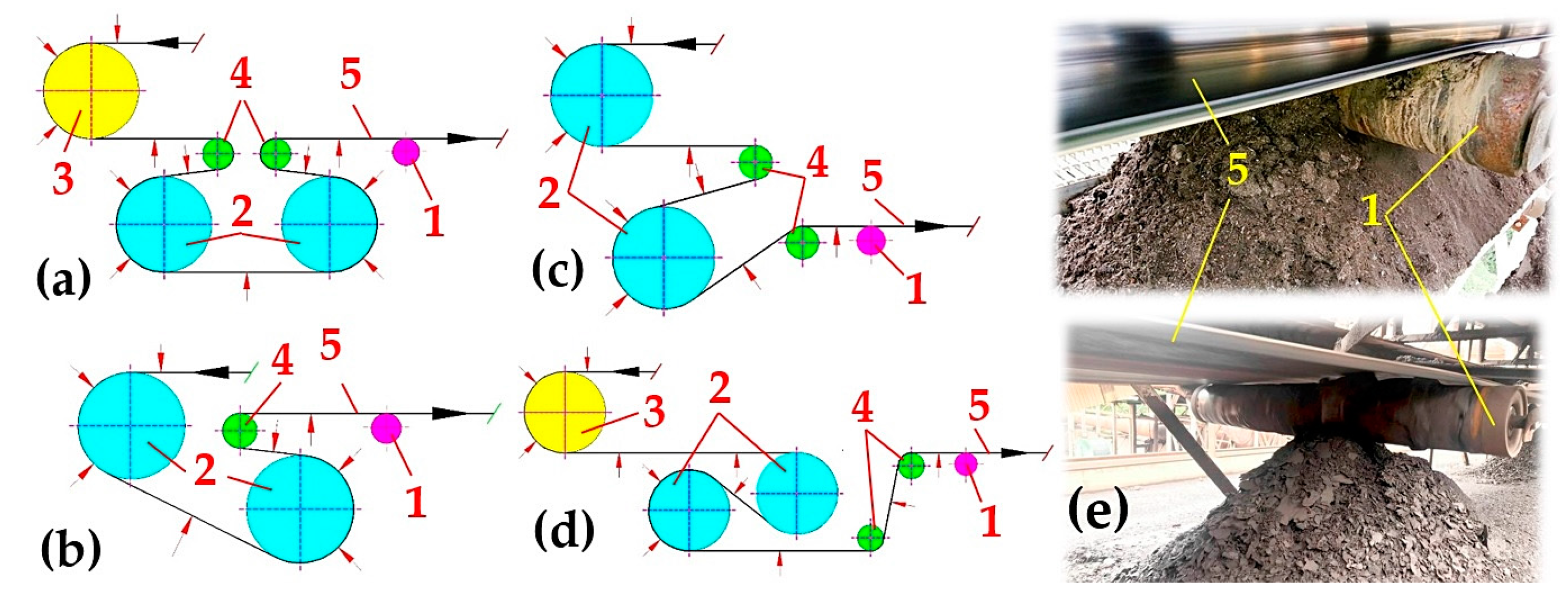
The disadvantage of both two-drum (
Figure 2ab) and three-drum drives is that the working run of the conveyor belt touches the casings of the conveyor rollers in the return run of the belt conveyor. An insufficiently cleaned surface of a conveyor belt from the adhered grains of the transported material causes the material to stick to the casings of the conveyor rollers, see
Figure 2c. These then vibrate as a result of the unbalanced mass when the rollers rotate.
In
Figure 2a to
Figure 2d, the red arrows indicate the working surface of the conveyor belt, i.e. the surface on which the conveyed material is carried in the working (upper) run of the conveyor belt. In the return run of the conveyor belt, this dirty surface of the conveyor belt meets the casings of the conveyor rollers [
26]. Despite the intensive brushing of dirt and adhered material grains from the working surface of the conveyor belt with devices called cleaners [
27,
28,
29,
30], dirt often remains on the surfaces of the conveyor belts, which accumulates on the rotating casings of the conveyor rollers.
Authors J Eliasson et al. in article [
31] they present an Internet of Things (IoT) architecture suitable for large scale sensor networks for condition monitoring. The developed technology has been applied and demonstrated for rotating conveyor belt rolls.
Authors R. Li et al. propose in the article [
32] to use radial grating vibration sensing technology for both belt conveyor roller vibration monitoring. This can then be used to predict the fault state in the roller and its position, using distributed optical fibber temperature measurement technology which can be used for “hot spot monitoring”.
This paper [
33] presents a recent review of acoustic and vibration signal-based fault detection for belt conveyor idlers using ML models. It also discusses major steps in the approaches, such as data collection, signal processing, feature extraction and selection, and ML model construction.
Article [
34] by X Liu et al. describes a test device for detecting vibration of conveyor belt rollers.
Machine learning-based techniques for condition monitoring and fault diagnosis of industrial equipment were used in the paper [
35] by authors J. Soares et al. Therefore, this paper presents a machine learning-based method for fault diagnosis in belt conveyor idlers.
2. Materials and Methods
The article is a follow-up to the article [
9], in which the effective values of the vibration velocity v
RMS [m·s
-1] were measured in three mutually perpendicular planes of a rotating (circumferential speed v
r = 1.28 to 6.93 m·s
-1) conveyor roller (with the casing diameter of 133 mm). The effective values of the vibration velocity v
RMS [m·s
-1] were measured for two different fittings of the conveyor roller axles. One is the traditional placement of the flattened ends of the roller axle in the notches of the trestles, see
Figure 3b on the fixed conveyor idler. The second way is to position these flattened ends of the roller axle in plastic brackets inserted into the specially designed steel trestles of the fixed conveyor idler.
The measurement of the effective values of vibration velocity v
RMS [m·s
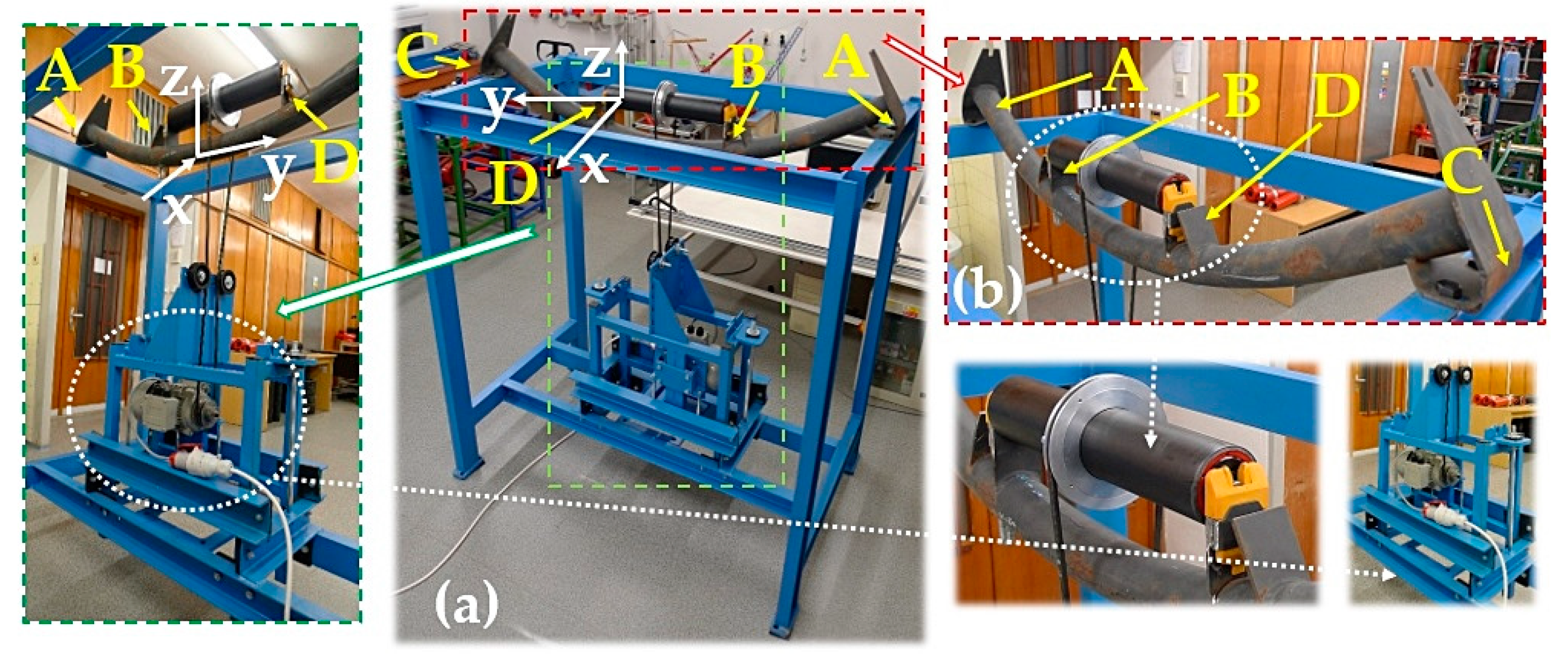
-1] was done using a laboratory machine, see
Figure 3a, which is located in a laboratory at the Department of Machine and Industrial Design, Faculty of Mechanical Engineering, VSB-Technical University of Ostrava. This device was designed by DvB-AF s.r.o., with its registered office at Meleček 227, 747 41 Hradec nad Moravicí, Žimrovice. A laboratory stand designed to measure the noise of a rotating roller is described in [
36,
37].
Researches on idlers were rather focused on rolling resistance, their energy consumption, load distribution, and failure analysis until now [
38,
39,
40,
41].
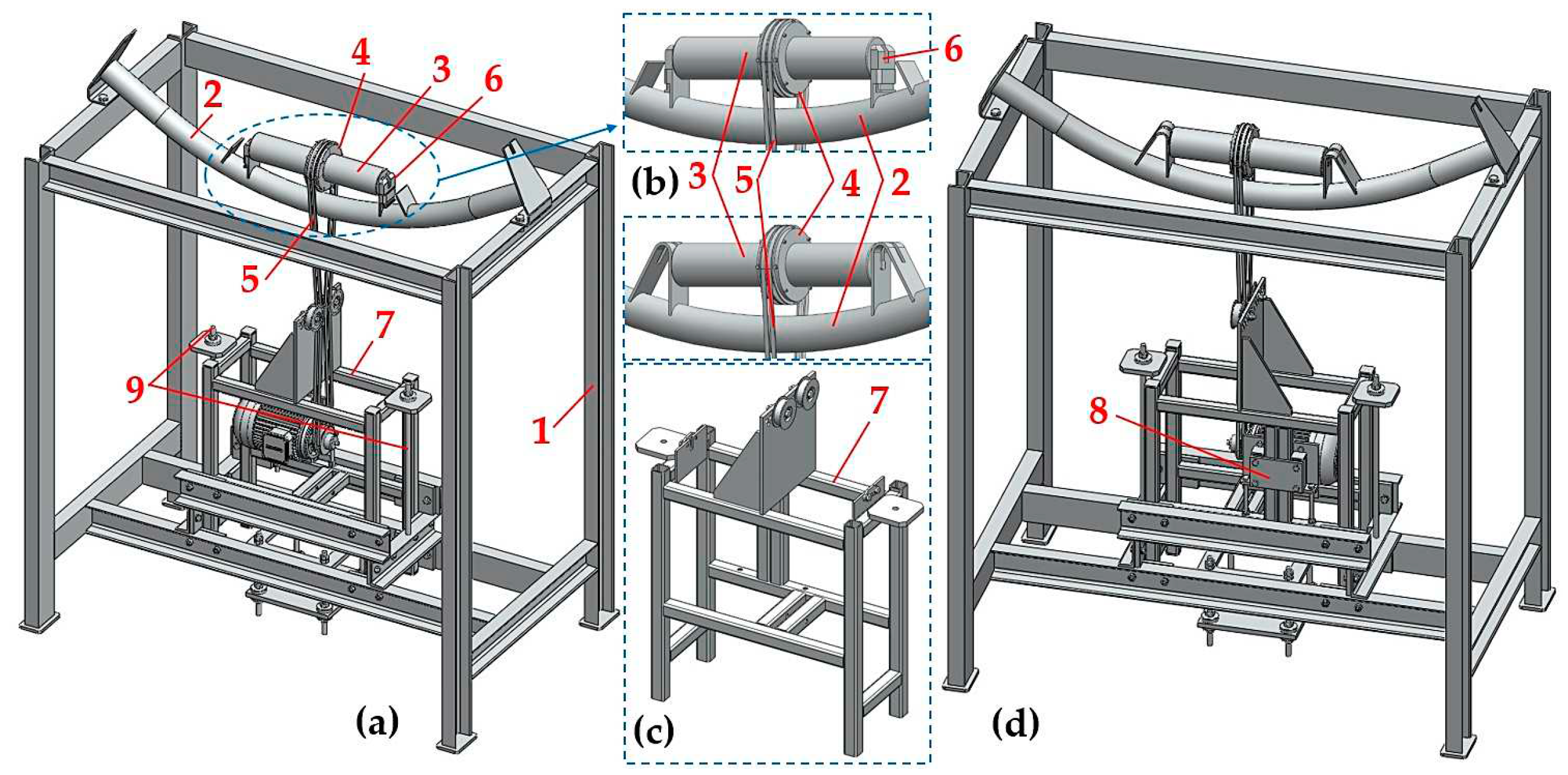
A 3D structural model of a laboratory machine created in SolidWorks®Premium 2012x64, SP5 is shown in
Figure 3. The laboratory machine consists of a steel frame
1, to which a vertically sliding drive support frame is mechanically attached
7, see
Figure 3c. The supporting device of the electric motor
8 is attached to the supporting frame of the drive
7, to which the electric motor is attached by screw connections (type 1AL90L-4, power engine P
e = 1.5 kW, revolutions n
e = 1445 min
-1). A V-belt pulley with a calculated diameter of d
w = 81.5 mm, is positioned onto the shaft of an electric ϕ 24 mm (with a tight key 8 x 7 x 40 mm). This pulley transmits the pulling force of the drive by friction to one (or two) V-belts
5 [
42] (type SPZ 2500 Lw 9.7 x 2513 La L=L). The revolutions of the electric motor n
e [min
-1] is controlled by an electric inverter (type YASKAWA VS-606 V7).
Laboratory measurements were carried out on conveyor rollers with various diameters Dr [mm] (133, 108 and 89), at the same circumferential speeds vr [m·s-1] of their casings.
In
Table 1, it is possible to read the required circumferential speed v
r [m·s
-1] of the conveyor roller, the required revolutions n
r [min
-1] of a roller with diameter D
r [m] and frequency f
i [Hz], by which the revolutions n
r [min
-1] of a conveyor roller is controlled by a frequency converter.
The theoretical magnitude of rotational speed n
r [m·s
-1] of the conveyor roller with diameter D
r [m] can be expressed based on knowing the transmission ratio i
w [-] and the constant c
i [-] according to the relation (3). The transmission ratio i
w [-] is defined by the ratio of the calculated diameter of the drive pulley d
w [m] and the diameter of the driven pulley D
w [m]. The constant c
i [-] expresses the ratio of the frequency value of f = 50 Hz (in Europe a unified distribution grid of 400/230V with a frequency of 50 Hz is used. In North America, it is a phase distribution system of 120V at a frequency of 60 Hz) and the frequency f
i [Hz] set on the display of the frequency converter.
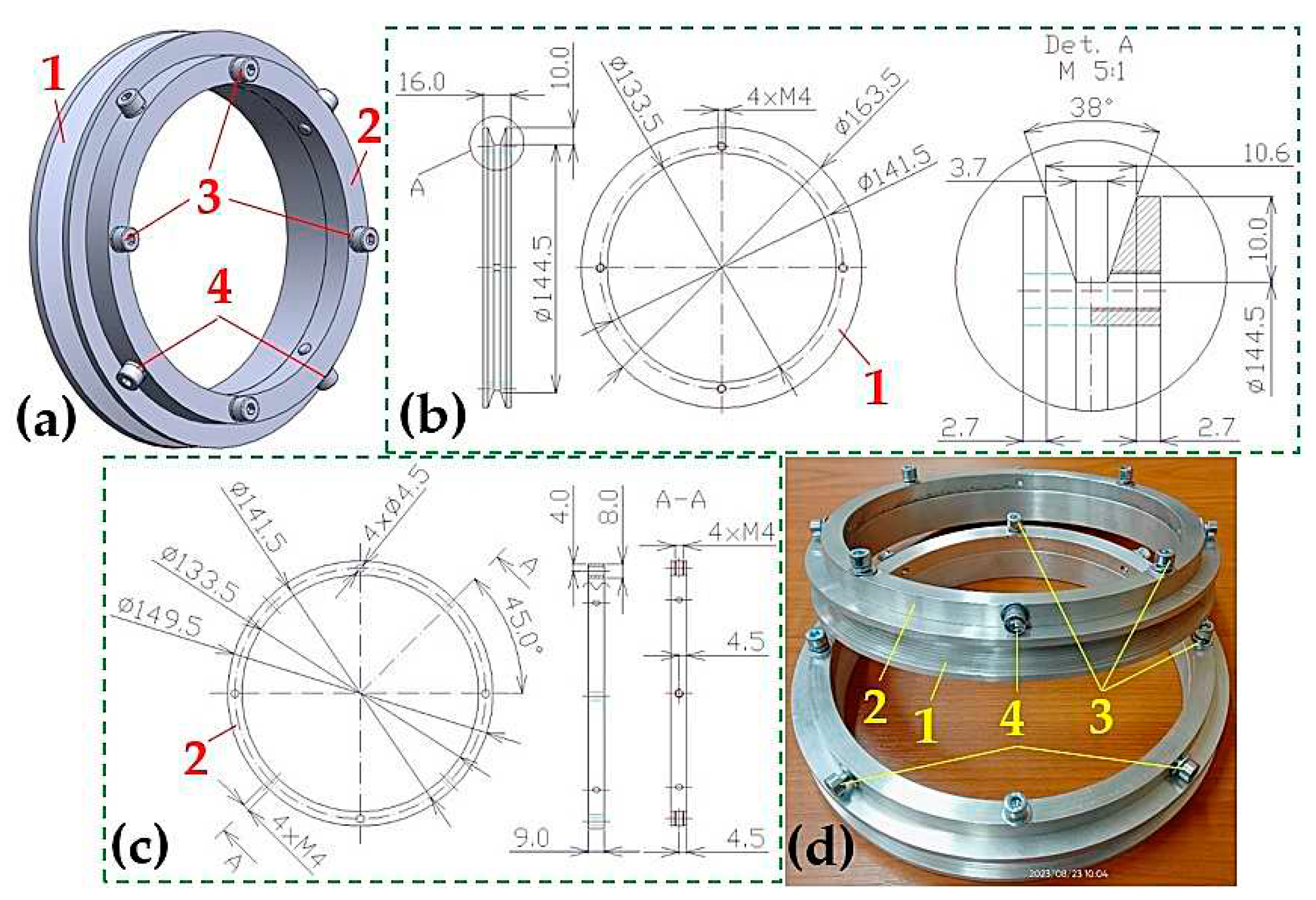
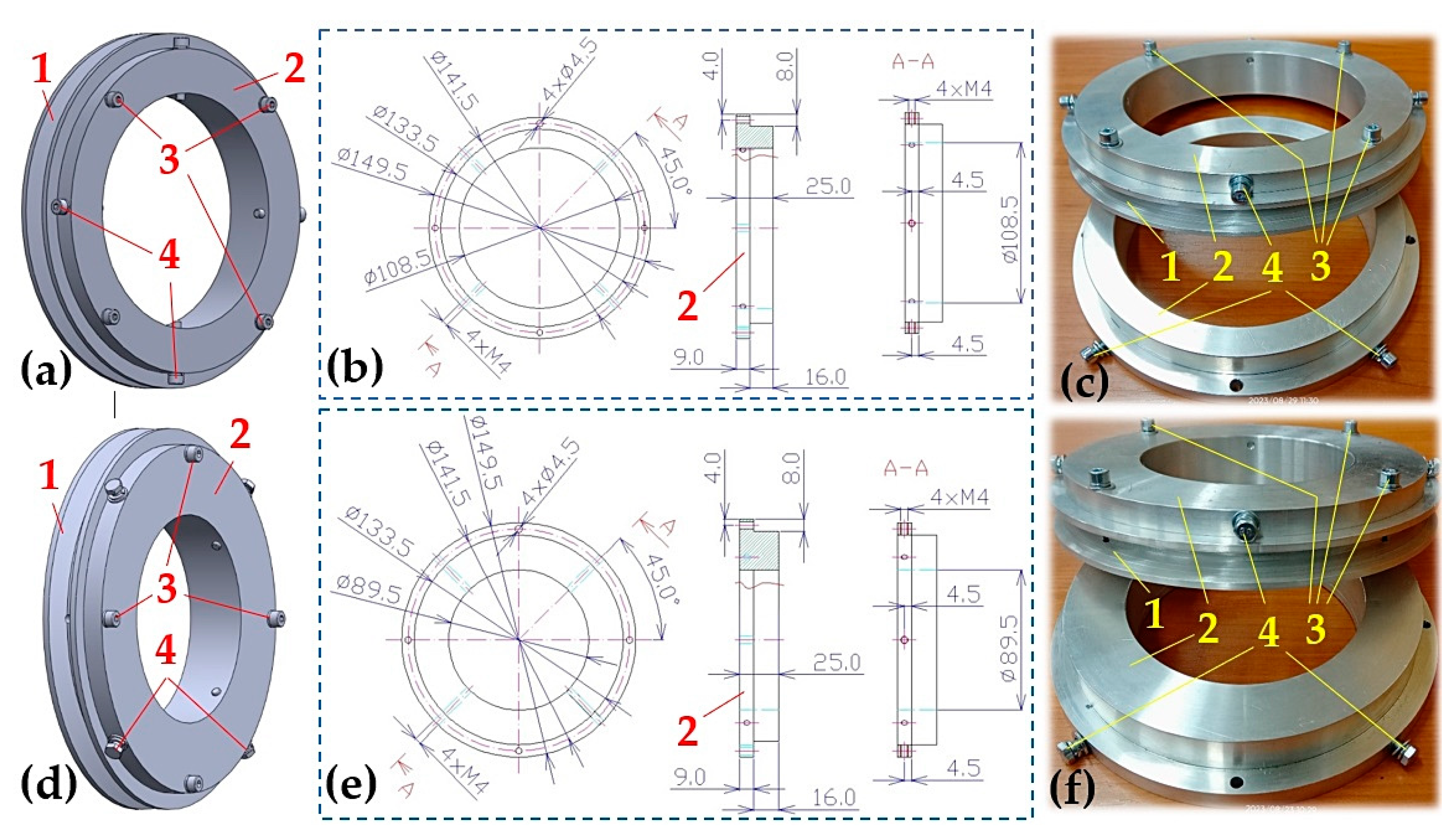
One or two so-called “V-belt pulley assembly” units are placed onto the tested conveyor roller (with a steel, plastic or rubberized casing) with a diameter of D
r = 133 mm (or 108 mm or 89 mm), see
Figure 4a. This assembly consists of a flange
2, with screw connections
3 attaching a pulley
1 with the calculated diameter of D
w = 153 mm. Prevention of this flange displacement
2 along the length of the conveyor roller casing, and prevention of flange rotation in relation to the circumference of the conveyor roller casing, is secured via screw connections
4.
An electric motor [
43], on the shaft of which a V-belt is slid (calculated diameter d
w = 81.5 mm), sets the V-belt into motion [
42]. The V-belt rotates the test conveyor roller at a revolution n
r [min
-1], corresponding to the circumferential velocity v
r [m·s
-1] of the conveyor roller, see
Table 1.
The design dimensions of flange
2 slid onto the ϕ108 mm conveyor roller is shown in
Figure 5b, and the design dimensions of flange
2 slid onto the ϕ89 mm conveyor roller is shown in
Figure 5e.
Steel casing, see
Figure 6a, or rubberized, see
Figure 6b, conveyor roller (ϕ133, ϕ108 or ϕ89 mm) rotates relative to the stable axle of the roller ϕ20 mm on 2 pcs of radial ball bearings 6204-2RS [
44].
In the article [
45] the authors M. Vasić et al. analysed failures of belt conveyor tension roller bearings. The article also examines the effects of tensioner pulley mounting position on bearing damage.
Plastic casing, see
Figure 7a, of the conveyor roller (ϕ133, ϕ108 or ϕ89 mm) rotates relative to the roller axle ϕ20 mm on 2 radial ball bearings 6204-2RS [
44].
The axle of the tested conveyor roller is inserted into a cut-out in the steel (
Figure 3b) or plastic (
Figure 8d) trestle of the fixed conveyor idler, which is screwed to the top surface of the steel frame of the laboratory machine (
Figure 3).
The vibrations generated by the rotating conveyor roller, transmitted to the sleeper of the fixed roller idler and the steel frame of the laboratory machine, were detected by two acceleration sensors PCE KS903.10 [
46], see
Figure 9. Signals from acceleration sensors were recorded by Dewesoft SIRIUSi-HS 6xACC, 2xACC+ [
47] measuring apparatus during experimental measurements. Time records of the measured vibration values were used by the Dewesoft X [
48] measuring program and transformed into effective vibration velocity values v
(*)RMS(fi) [mm·s
-1] in the range of 10÷1·10
4 Hz (this frequency range is applied in the ISO 10816-3 standard [
49]). Effective velocity values v
(*)RMS(fi) [mm·s
-1] (where * presents the x, y or z axis of the coordinate system) with periodic courses were displayed using a PS monitor in the environment of the Dewesoft X measuring software.
The speed of the conveyor roller was scanned by an optical laser sensor DS-TACHO-3 [
50,
51].
4. Discussion
The aim of this paper was to detect vibrations transmitted by the rotating casing of the conveyor roller to the fixed conveyor idler and also to the steel frame of the laboratory machine to which the fixed conveyor idler is attached. The measurement of the vibrations of the roller casing installed on a laboratory stand, and an assessment of the technical condition of the belt conveyor rollers after the specified operating time, were also carried out in [
33]. In the conclusions of the vibrations measurement of the conveyor roller done by both laboratory machines similar results were achieved.
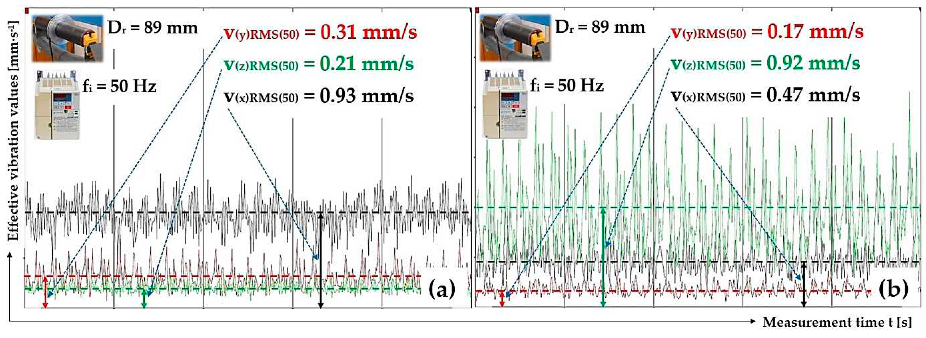
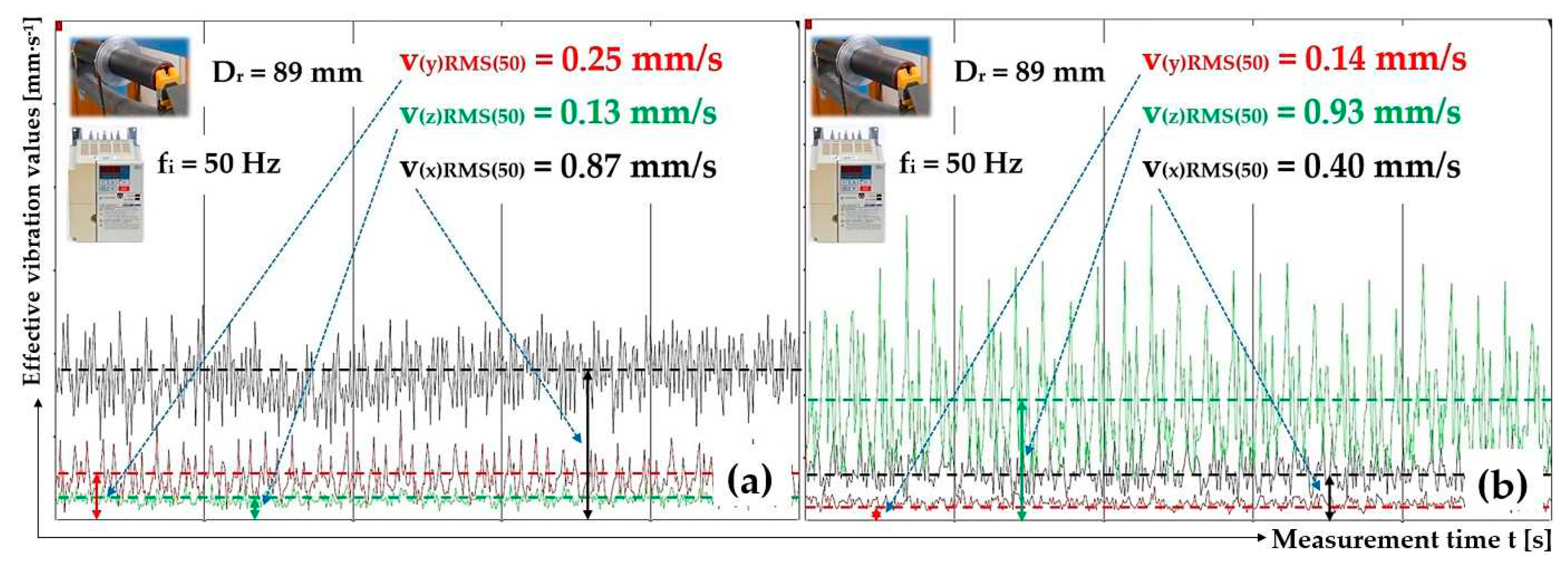
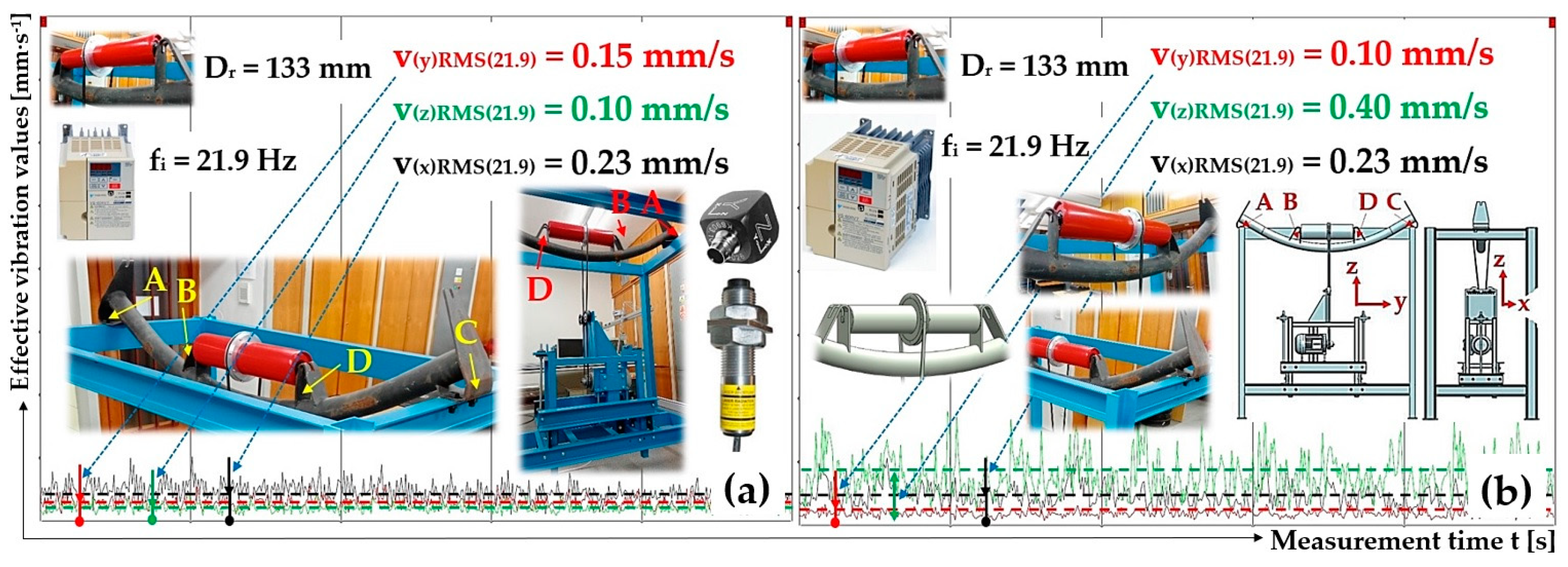
From the measured time curves of the vibration value (see
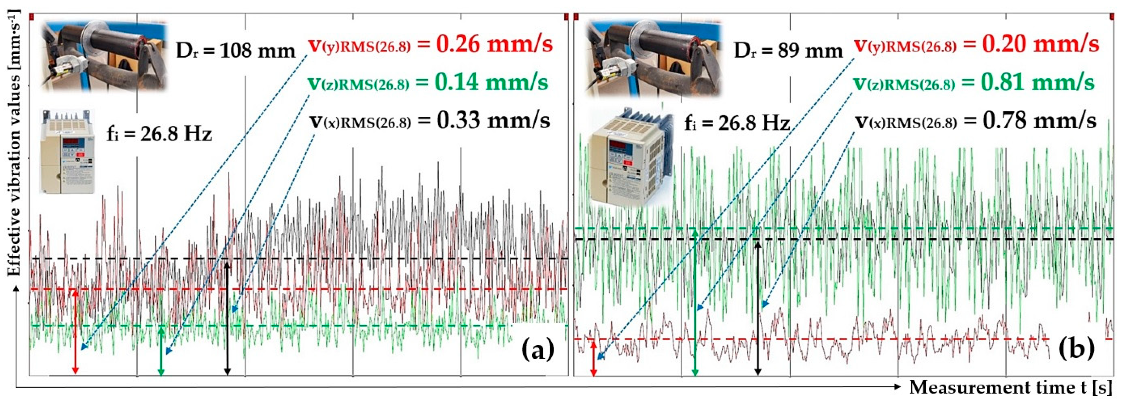
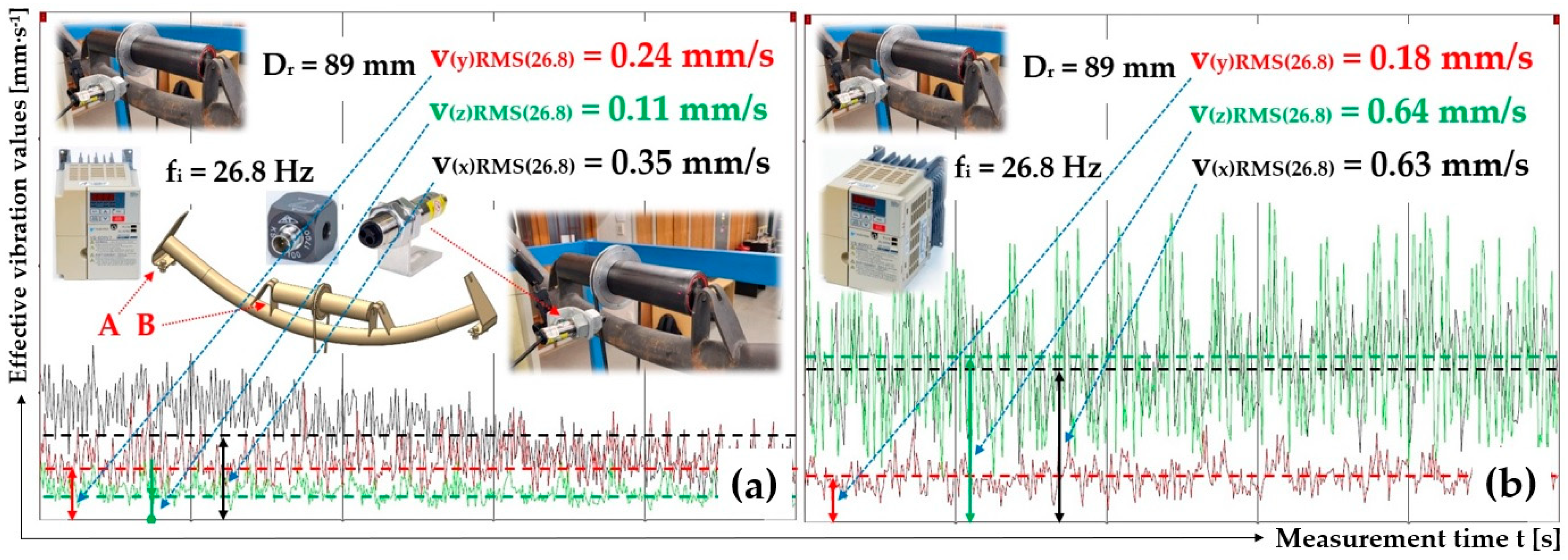
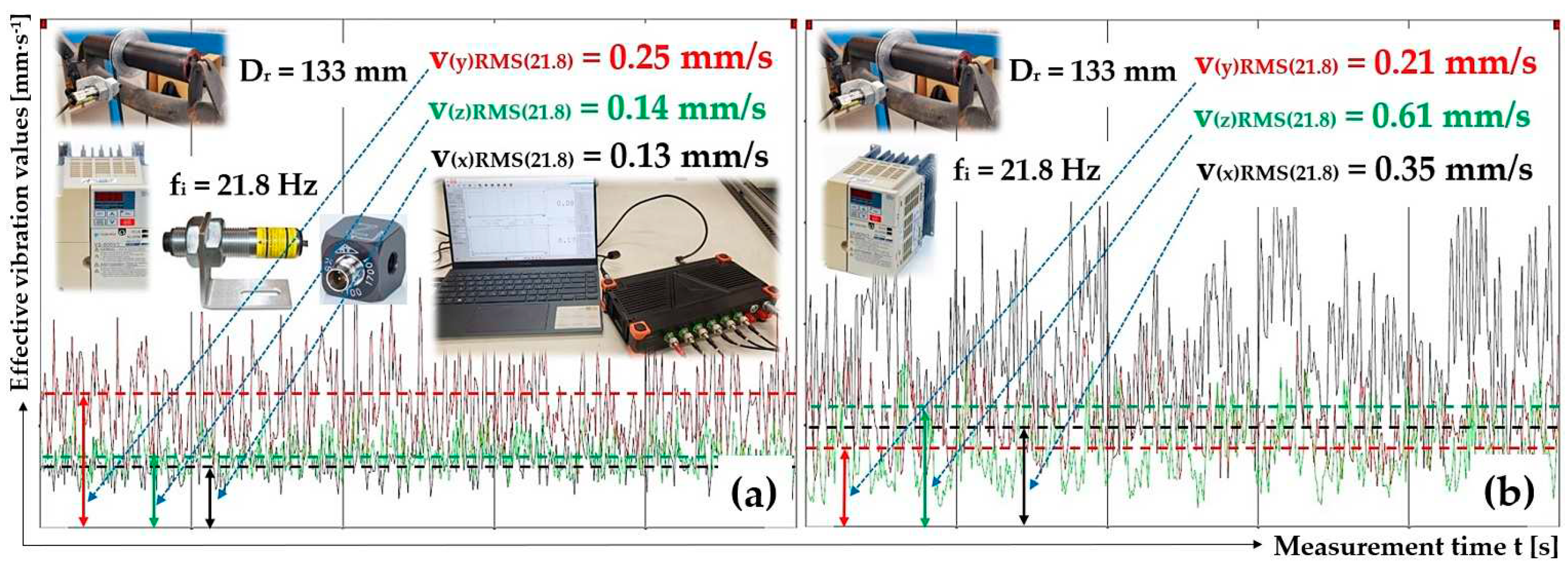
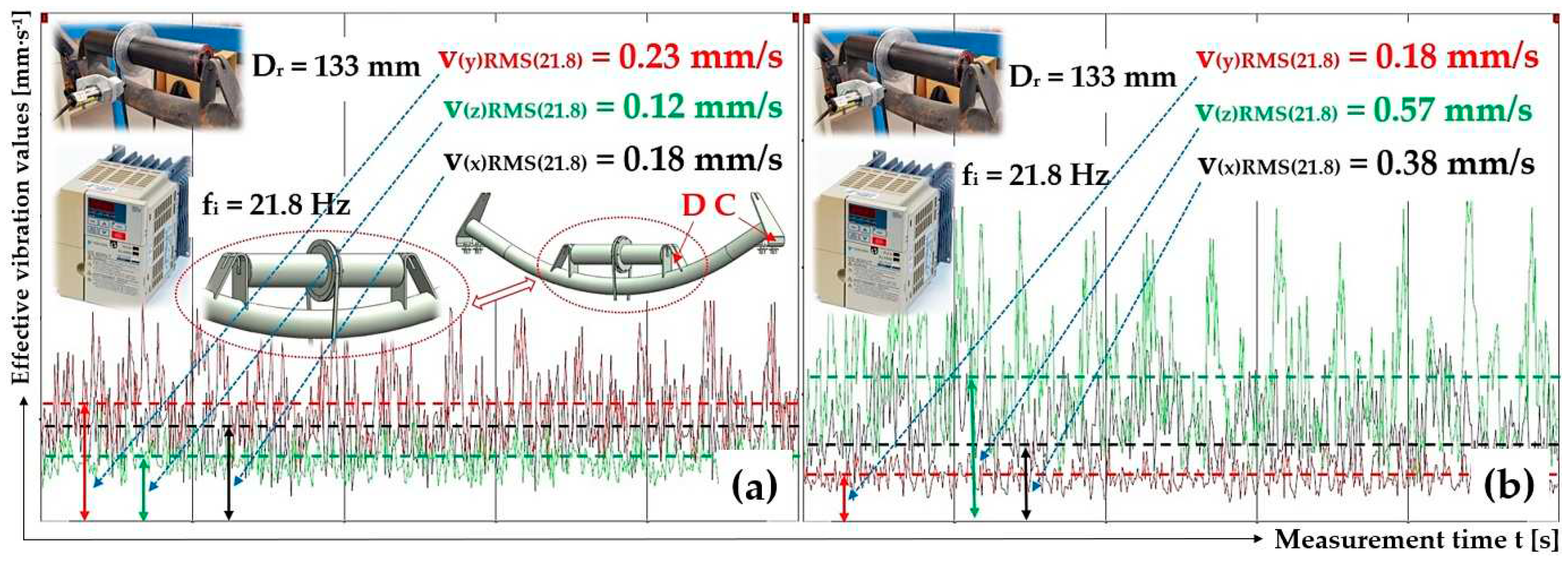
Figure 12 to
Figure 35) for conveyor rollers of 89 mm, 108 mm and 133 mm diameters rotating at circumferential speeds 1.25, 2.5 and 3.85 m·s
-1, with the help of the DEWESoft X software, the effective values for vibration velocities were determined, and these are listed in
Table 3 to
Table 26.
The vibration values of the conveyor rollers show that the effective values of the vibration velocity increase with the increasing speed (circumferential speed) of the conveyor roller casings. This assumption is confirmed in the findings presented in the article [
9] by Klimenda et al., who deal in their article [
11] with the measurement of the noise and vibration of rollers designed for belt conveyors. The three highest acceleration values depending on the frequency of the vibration in each direction (
x, y, z) correspond to the measured effective vibration values v
(*)RMS(fi) [mm·s
-1] in coordinate axes
(x, y, z). For more information, see Chapters 3.1 to 3.4.
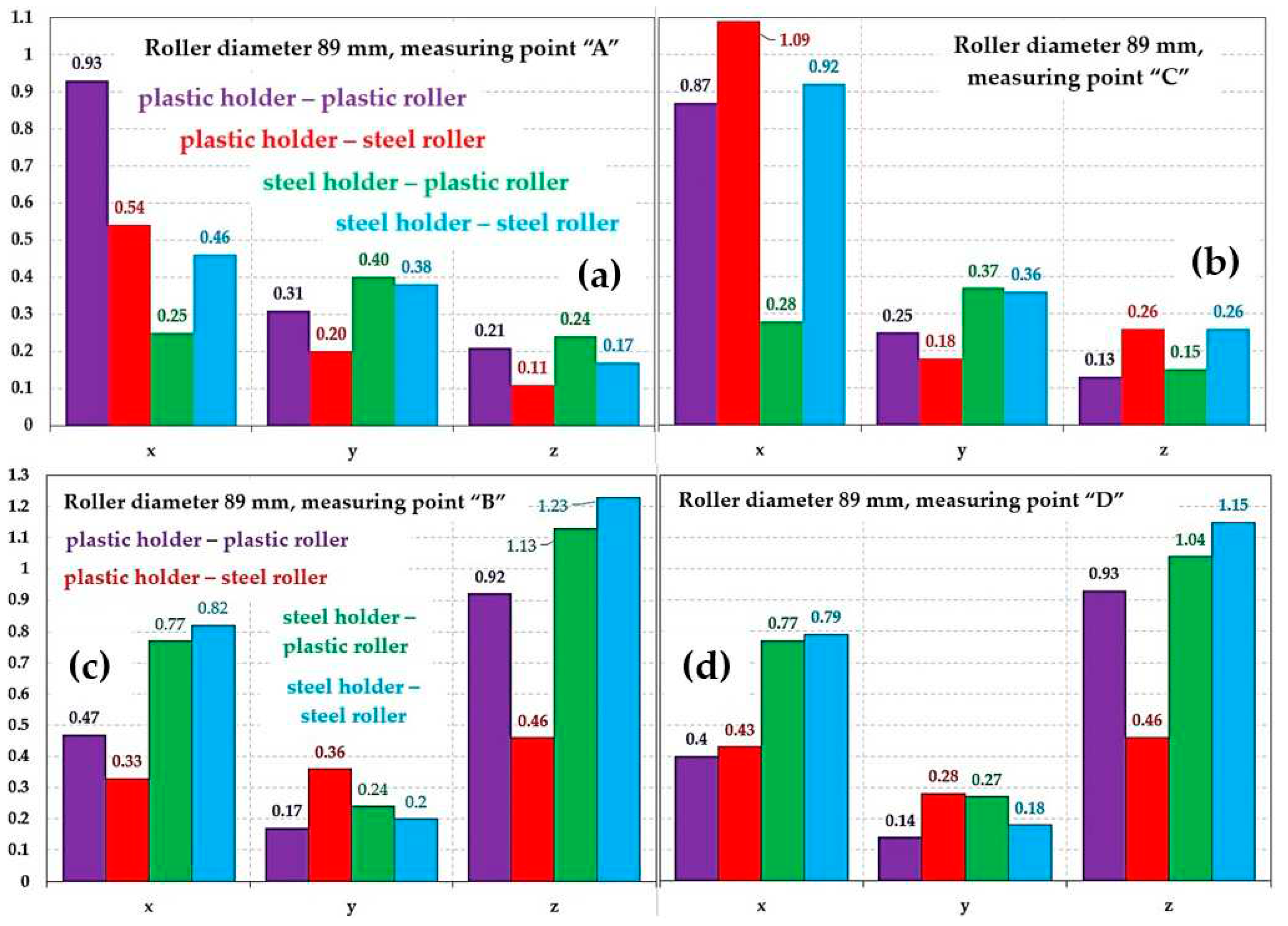
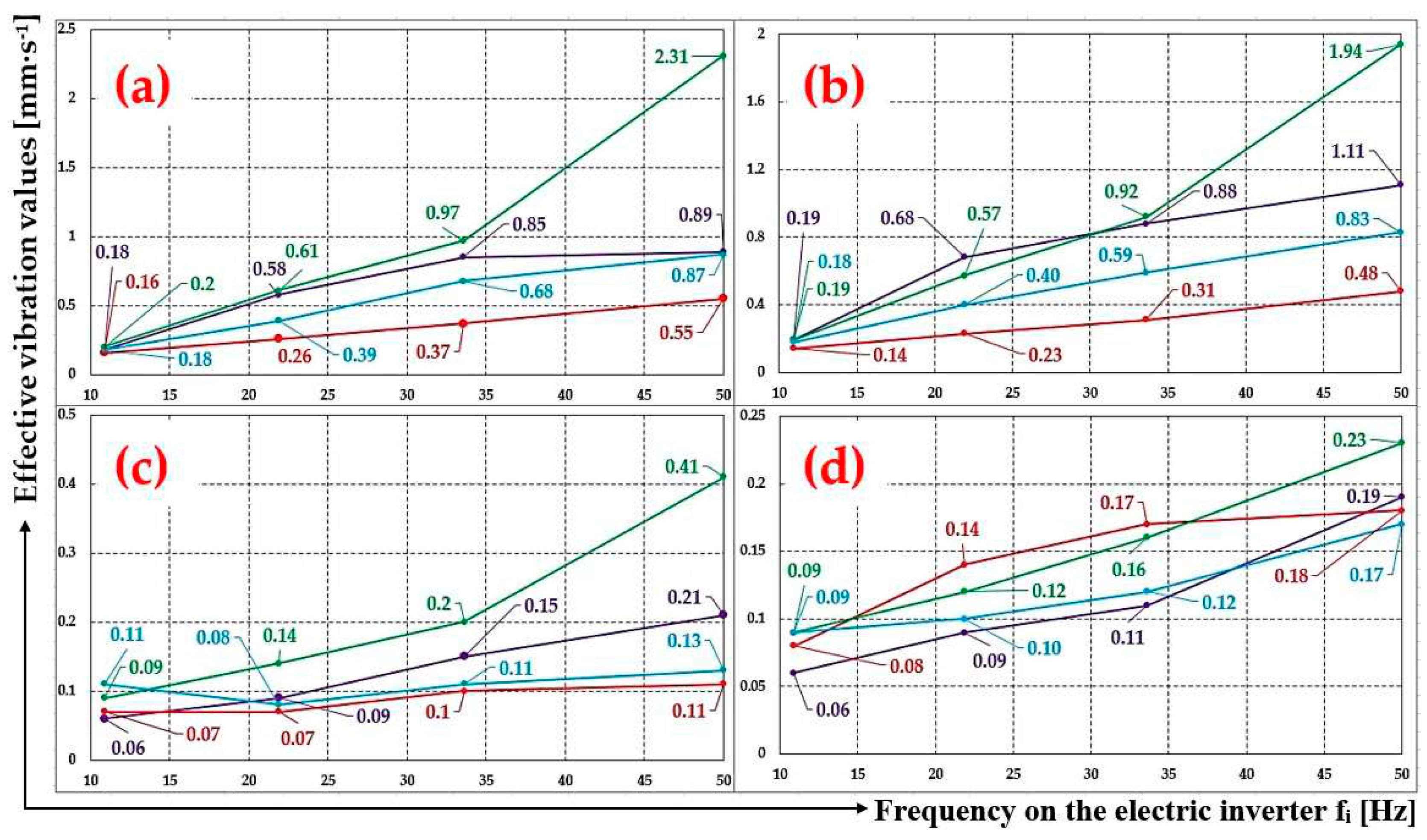
Figure 36(c) and
Figure 36(d) show that the highest effective values of the vibration velocity v
(*)RMS(fi) [mm·s
-1] reach the conveyor roller with ϕ89 mm diameter placed in the steel trestle of a fixed conveyor idler, and that is in the “z“ axis (vertical direction). This fact can be traced in the article [
12], in which the three highest values of acceleration depending on the frequency of vibration in each direction are described.
At the revolutions of the steel casing conveyor roller n
r = 825 mim
-1 and the roller axle placement of the conveyor with a 89 mm diameter into plastic brackets (see
Figure 11 part B), the effective value of the vibration velocity is v
(*)RMS(fi) [mm·s
-1] in axis “z“ is reaching 37.4 % of the value v
(*)RMS(fi) [mm·s
-1], compared to placing this roller in a steel trestle.
When the axle of the steel conveyor roller ϕ89 mm is fitted into the plastic brackets (see
Figure 11 part D), the effective value of the vibration velocity v
(*)RMS(fi) [mm·s
-1] in the “z“ axis reaches 40 % of value v
(*)RMS(fi) [mm·s
-1], unlike when placed in a steel trestle.
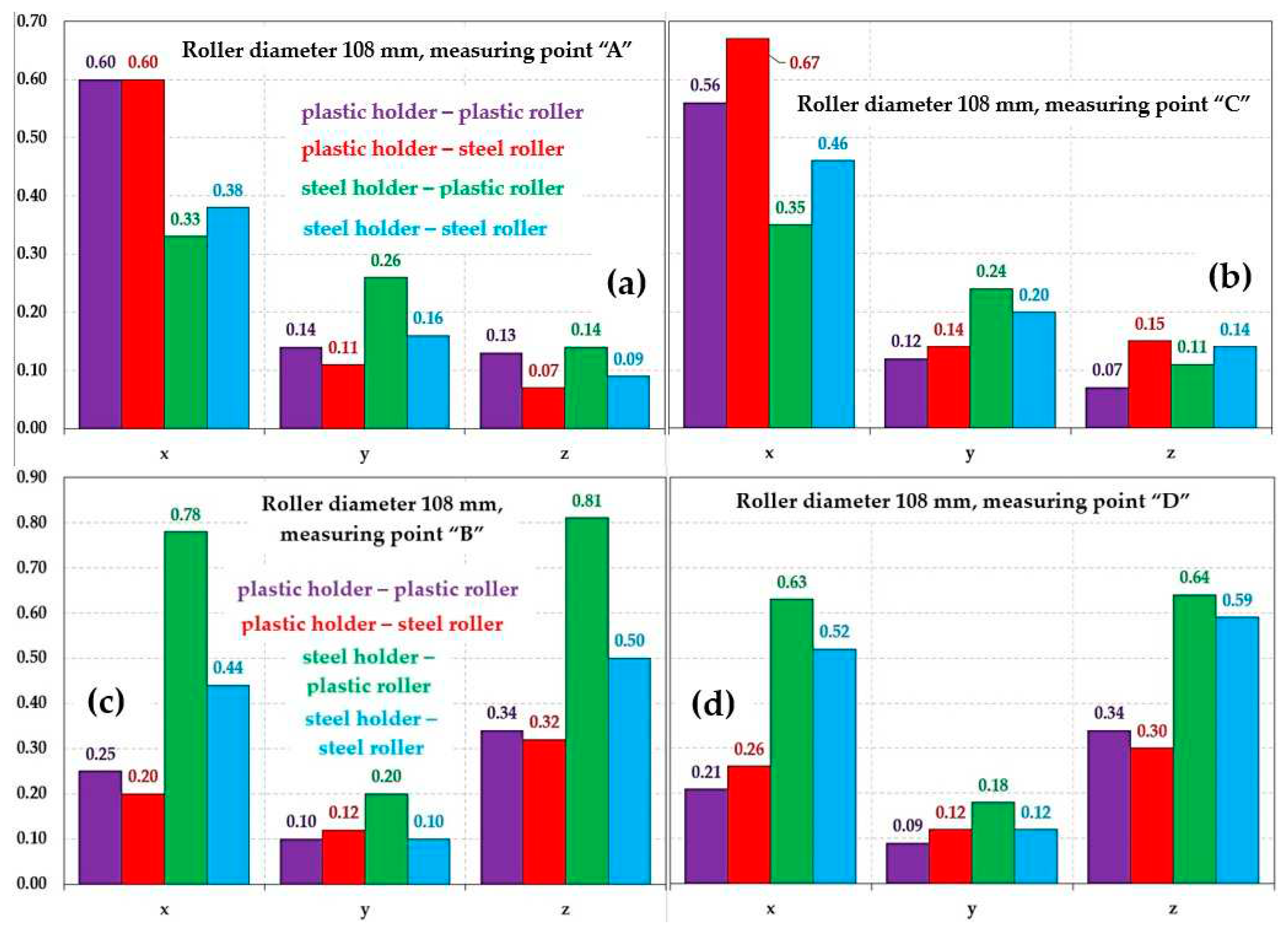
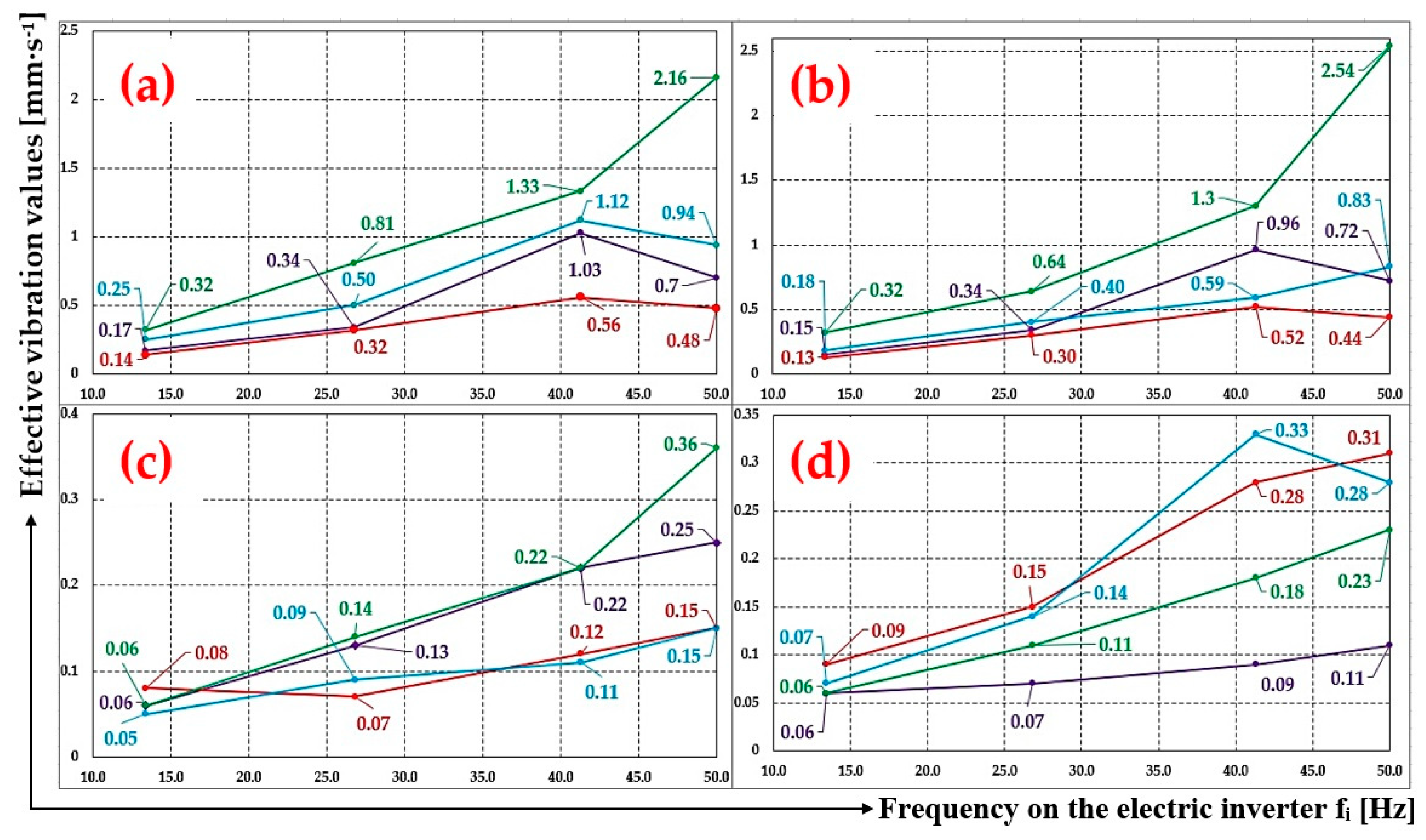
Figure 37c,d show that the highest effective values of the vibration velocity v
(*)RMS(fi) [mm·s
-1] reach the conveyor roller with ϕ108 mm diameter placed in the steel trestle of a fixed conveyor idler, and that is in the “z“ axis (vertical direction).
At the revolutions of the steel casing conveyor roller n
r = 442 mim
-1 and the roller axle placement of the conveyor with a 108 mm diameter into plastic brackets (see
Figure 11 part B), the effective value of the vibration velocity is v
(*)RMS(fi) [mm·s
-1] in axis “z“ is reaching 41.9 % of the value v
(*)RMS(fi) [mm·s
-1], compared to placing this roller in a steel trestle.
When the axle of the steel conveyor roller ϕ108 mm is fitted into the plastic brackets (see
Figure 11 part D), the effective value of the vibration velocity v
(*)RMS(fi) [mm·s
-1] in the “z“ axis reaches 46.9 % of value v
(*)RMS(fi) [mm·s
-1], unlike when placed in a steel trestle.
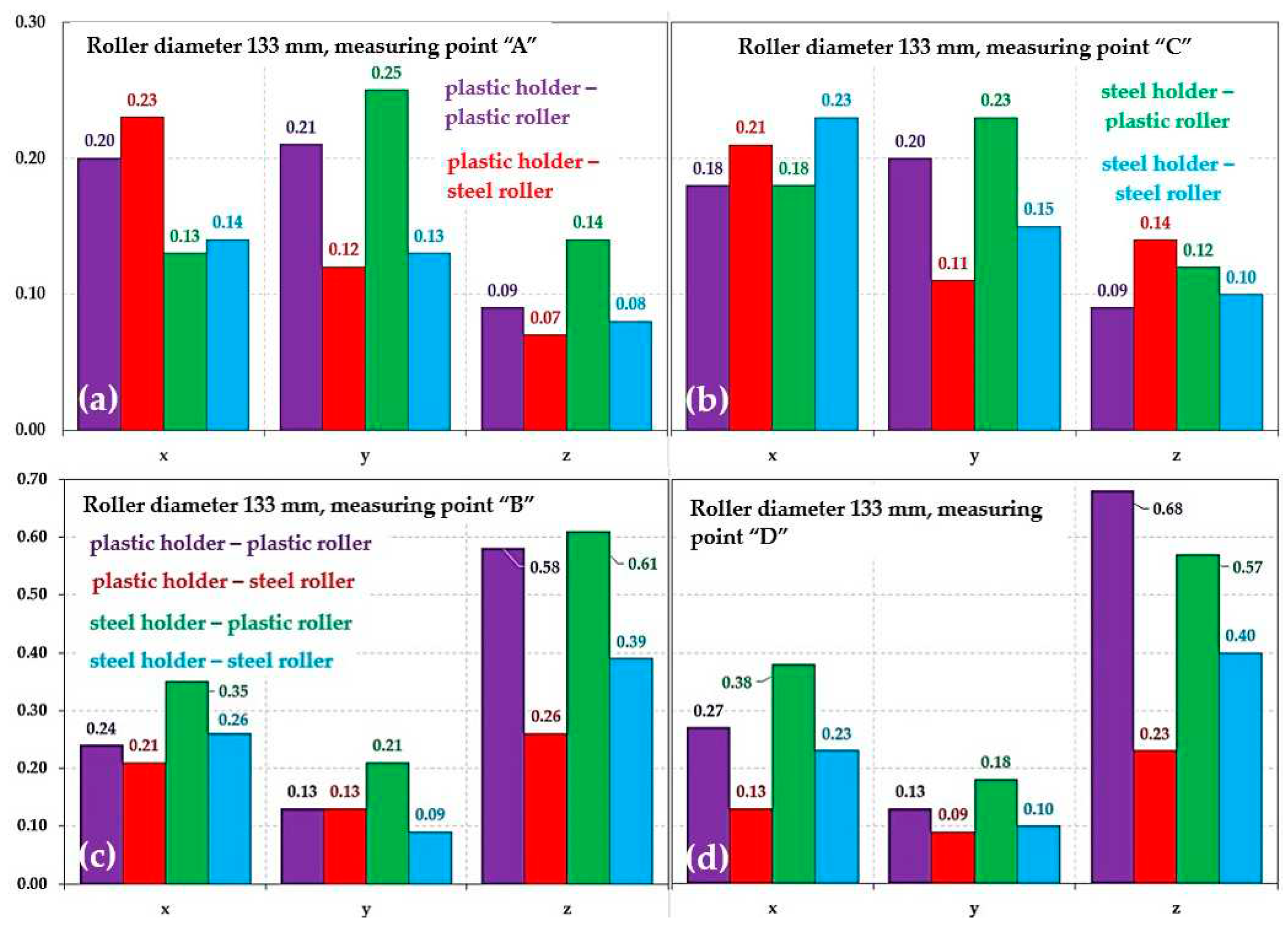
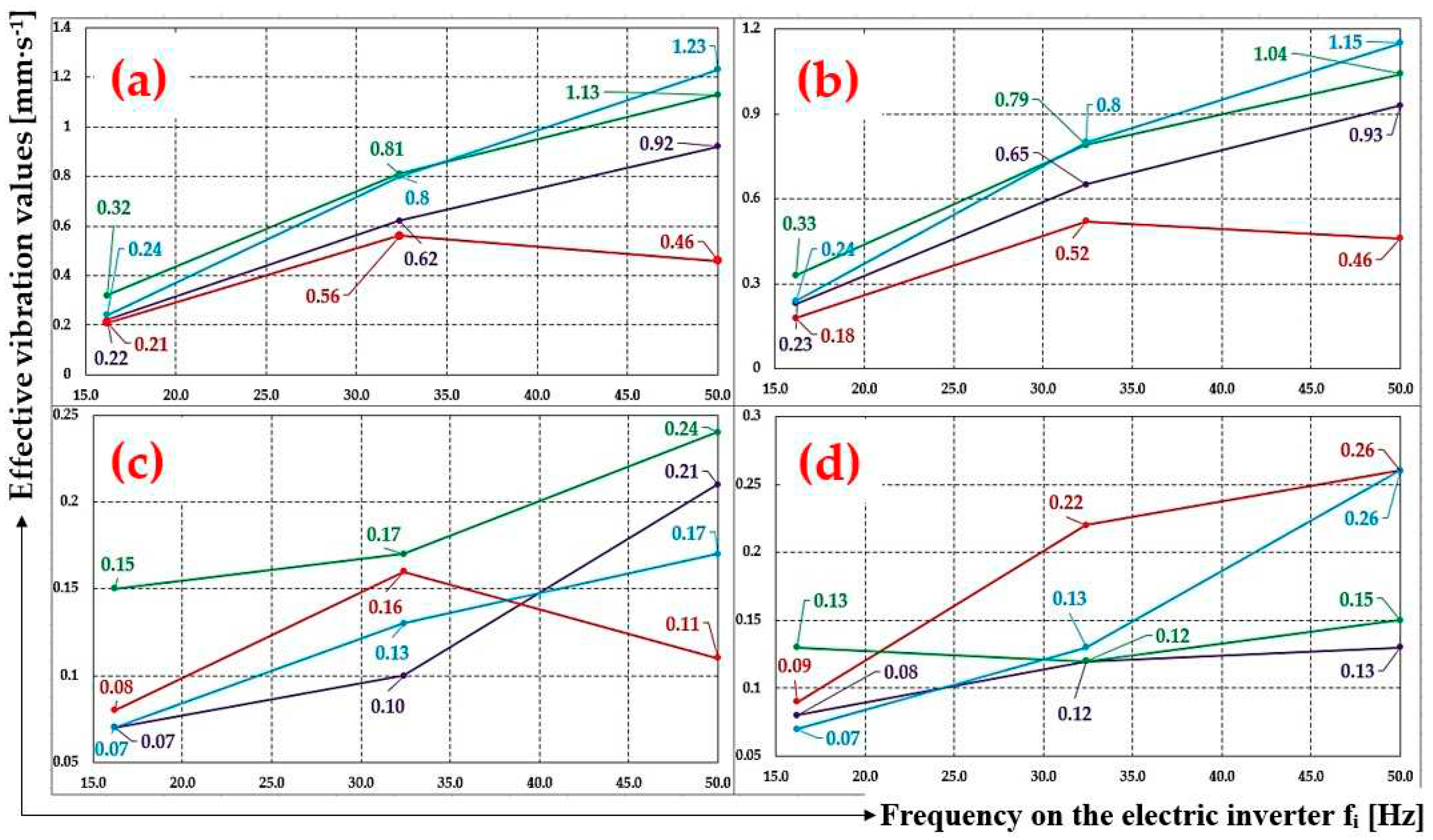
From
Figure 38c,d, it is clear that the biggest differences in the effective values of the vibration velocity v
(*)RMS(fi) [mm·s
-1] are reached by the conveyor rollers with a 133 mm diameter, when these are placed in the fixed trestle of a conveyor idle, and these are reached in the “z“ axis direction (vertical direction).
At the revolutions of the steel casing conveyor roller n
r = 361 mim
-1 and the roller axle placement of the conveyor with a 108 mm diameter into plastic brackets (see
Figure 11 part B), the effective value of the vibration velocity is v
(*)RMS(fi) [mm·s
-1] in axis “z“ is reaching 66.7 % of the value v
(*)RMS(fi) [mm·s
-1], compared to placing this roller in a steel trestle.
When the axle of the steel conveyor roller ϕ133 mm is fitted into the plastic brackets (see
Figure 11 part D), the effective value of the vibration velocity v
(*)RMS(fi) [mm·s
-1] in the “z“ axis reaches 57.5 % of value v
(*)RMS(fi) [mm·s
-1], unlike when placed in a steel trestle.
In
Figure 39, we can see the effective vibration values v
(*)RMS(fi) [mm·s
-1] for the rotating conveyor rollers measured in the points A to D, of which the plastic or steel casing of a 133 mm diameter rotates at circumferential speed of v
r = 5.74 (3.84, 2.5 or 1.25) m·s
-1, provided that the flattened ends of the conveyor roller axles are fitted into the steel or plastic trestle of the fixed conveyor idler.
Graphs (a) to (d) show that the effective vibration values v(*)RMS(fi) [mm·s-1] of the rotating conveyor rollers reach the highest values at higher frequencies set on the frequency converter (the speed of the driving electric motor was controlled by a frequency converter) corresponding to the revolutions of the conveyor rollers.
Research by K. Hicke at al. [
53] focuses on monitoring the acoustic condition and detection of roller faults in industrial conveyor belts.
Graphs (a) to (d) also show that higher effective vibration values v(*)RMS(fi) [mm·s-1] that were measured in points A to D, in the case when the axles of the conveyor rollers were placed in a steel trestle (green and blue curves) than when the axles of the conveyor rollers were positioned in plastic brackets (purple and red colour curves).
In
Figure 40, we can see the effective vibration values v
(*)RMS(fi) [mm·s
-1] for the rotating conveyor rollers measured in the points A to D, of which the plastic or steel casing of a 108 mm diameter rotates at circumferential speed of v
r = 4.66 (3.84, 2.5 or 1.25) m·s
-1, provided that the flattened ends of the conveyor roller axles are fitted into the steel or plastic trestle of the fixed conveyor idler.
In
Figure 41, we can see the effective vibration values v
(*)RMS(fi) [mm·s
-1] for the rotating conveyor rollers measured in the points A to D, of which the plastic or steel casing of a 89 mm diameter rotates at circumferential speed of v
r = 3.84 (2.5 or 1.25) m·s
-1, provided that the flattened ends of the conveyor roller axles are fitted into the steel or plastic trestle of the fixed conveyor idler.
The provided vibration measurements of the rotating conveyor rollers with their axles fitted in the steel or plastic trestles of the fixed conveyor idler, performed on the non-rotating parts of our laboratory machine is sufficient to appropriately characterize operating conditions with regard to trouble-free operation. Measurements were made with regard to ISO 10816-1 [
6], which specifies the general conditions and procedures for the measurement and evaluation of vibration by means of measurements carried out on non-rotating parts. The general evaluation criteria, which are presented in the form of both magnitude and vibration change, apply to both in-service monitoring and acceptance tests. The criteria were set primarily with regard to ensuring the reliable, safe and long-term operation of the machine (i.e., a belt conveyor) while minimizing the adverse effects on the connected equipment.
Vibrations lead to fatigue failure or damage which is harmful to engine supporting structures [
54].
Figure 1.
The endless loop of a conveyor belt supported by conveyor rollers.
Figure 1.
The endless loop of a conveyor belt supported by conveyor rollers.
Figure 2.
Two-drum driving station (a) type Ω, (b) type C, (c) without a boom, (d) type S, (e) transported material stuck on the casing of the conveyor roller. 1—conveyor roller, 2—drive drum, 3—dump drum, 4—transmission drum, 5—conveyor belt.
Figure 2.
Two-drum driving station (a) type Ω, (b) type C, (c) without a boom, (d) type S, (e) transported material stuck on the casing of the conveyor roller. 1—conveyor roller, 2—drive drum, 3—dump drum, 4—transmission drum, 5—conveyor belt.
Figure 3.
(a) Structural 3D design of a laboratory machine—front view, (b) conveyor roller placed in the trestle of a fixed conveyor idler, (c) drive frame, (d) laboratory machine—rear view. 1—steel frame, 2—fixed conveyor idler, 3—conveyor roller, 4—driven pulley, 5—V-belt, 6—plastic bracket, 7—drive support frame, 8—electric motor support device.
Figure 4.
(a) A 3D model of V-belt pulley assembly, (b) the dimensions of the pulley, (c) the dimensions of the flange for the conveyor roller ϕ133 mm, (d) manufactured V-belt pulley assembly. 1—V-belt pulley, 2—flange, 3—screw M4x16 DIN 912, 4—screw M4x10 DIN 912.
Figure 4.
(a) A 3D model of V-belt pulley assembly, (b) the dimensions of the pulley, (c) the dimensions of the flange for the conveyor roller ϕ133 mm, (d) manufactured V-belt pulley assembly. 1—V-belt pulley, 2—flange, 3—screw M4x16 DIN 912, 4—screw M4x10 DIN 912.
Figure 5.
(a) A 3D model of the V-belt pulley assembly, (b) flange dimensions for ϕ108 mm conveyor roller, (c) manufacture V-belt pulley assembly, (d) a 3D model of the V-belt pulley assembly, (e) flange dimensions for ϕ89 mm conveyor roller, (f) manufactured V-belt pulley assembly. 1—V-belt pulley, 2—flange, 3—screw M4x16 DIN 912, 4—screw M4x25 DIN 912 (screw M4x35 DIN 933).
Figure 6.
Conveyor roller (a) steel, (b) rubberized, (c) a 3D model of a conveyor roller fitted with two pieces V-belt pulley assembly. 1—V-belt pulley, 2—flange, 3—screw M4x16 DIN 912, 4—screw M4x10 (25) DIN 912 (M4x35 DIN 933), 5—conveyor roller ϕ133 mm (or ϕ108 mm or ϕ89 mm).
Figure 6.
Conveyor roller (a) steel, (b) rubberized, (c) a 3D model of a conveyor roller fitted with two pieces V-belt pulley assembly. 1—V-belt pulley, 2—flange, 3—screw M4x16 DIN 912, 4—screw M4x10 (25) DIN 912 (M4x35 DIN 933), 5—conveyor roller ϕ133 mm (or ϕ108 mm or ϕ89 mm).
Figure 7.
(a) plastic conveyor roller, (b) conveyor roller fitted with two pieces of a V-belt pulley assembly, (c) roller axle placed in a plastic bracket. 1—V-belt pulley, 2—flange, 3—screw M4x16 DIN 912, 4—screw M4x10 (25) DIN 912 (M4x35 DIN 933), 5—conveyor roller ϕ133 mm (or ϕ108 mm, or ϕ89 mm), 6—plastic bracket to hold the roller axles.
Figure 8.
Plastic bracket for the conveyor roller axle inserted into a modified trestle of a fixed roller idler (a) 3D structural design, (b) 3D structural design, (c) the implemented solution of the plastic bracket, plastic holder, (d) conveyor roller mounted in the trestle of a fixed roller idler. 1—conveyor roller, 2—plastic bracket.
Figure 9.
Measuring chain for detecting and recording the vibrations of rotating rollers on a laboratory machine.
Figure 9.
Measuring chain for detecting and recording the vibrations of rotating rollers on a laboratory machine.
Figure 10.
(
a) fixed conveyor idler—basic dimensions (in
Table 2), (
b) roller support with traditional trestles, (
c) conveyor idler with plastic brackets in trestles. 1—trestle, 2—sleeper, 3—plastic bracket.
Figure 10.
(
a) fixed conveyor idler—basic dimensions (in
Table 2), (
b) roller support with traditional trestles, (
c) conveyor idler with plastic brackets in trestles. 1—trestle, 2—sleeper, 3—plastic bracket.
Figure 11.
(a) A laboratory machine used to measure the vibrations of the conveyor rollers; (b) measuring points A, B, C, and D on a fixed conveyor idler where accelerometers are placed.
Figure 11.
(a) A laboratory machine used to measure the vibrations of the conveyor rollers; (b) measuring points A, B, C, and D on a fixed conveyor idler where accelerometers are placed.
Figure 12.
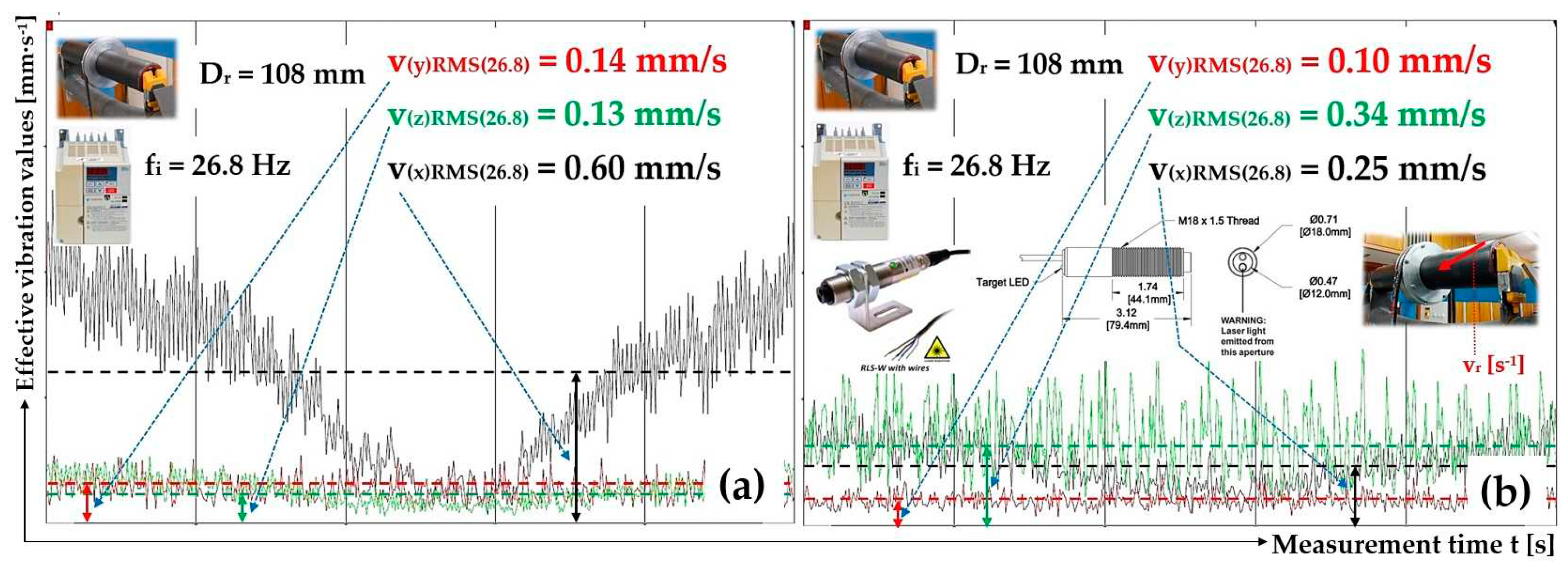
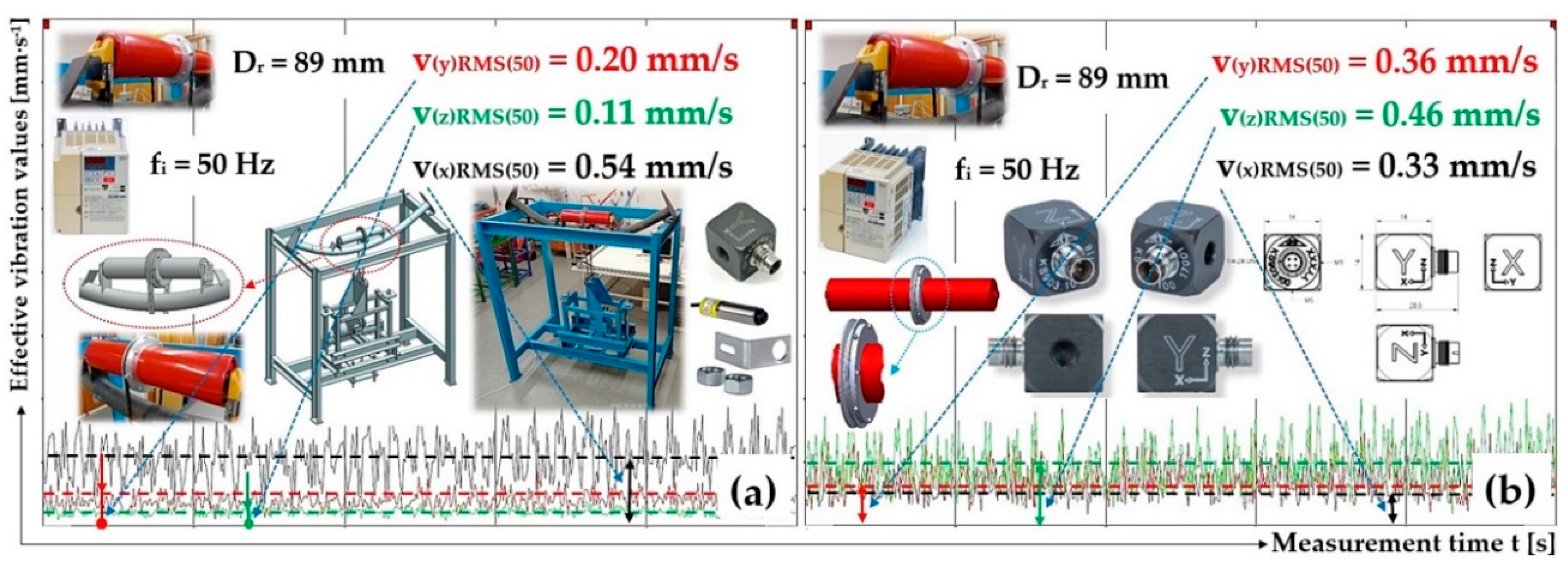
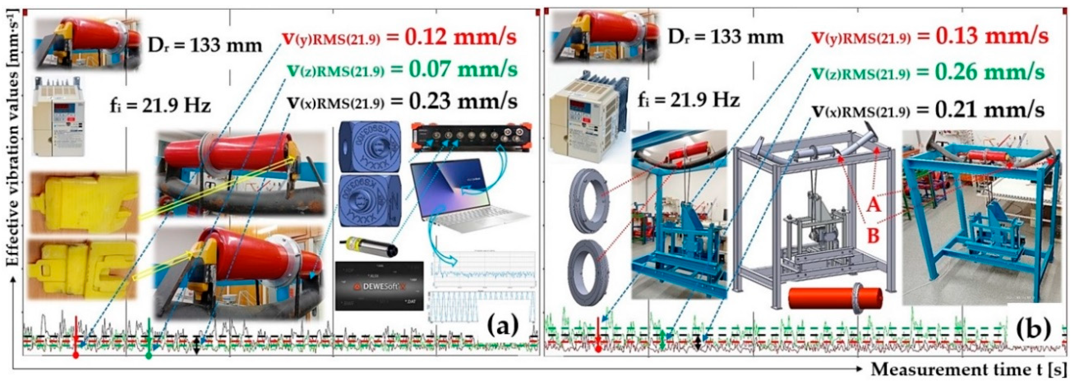
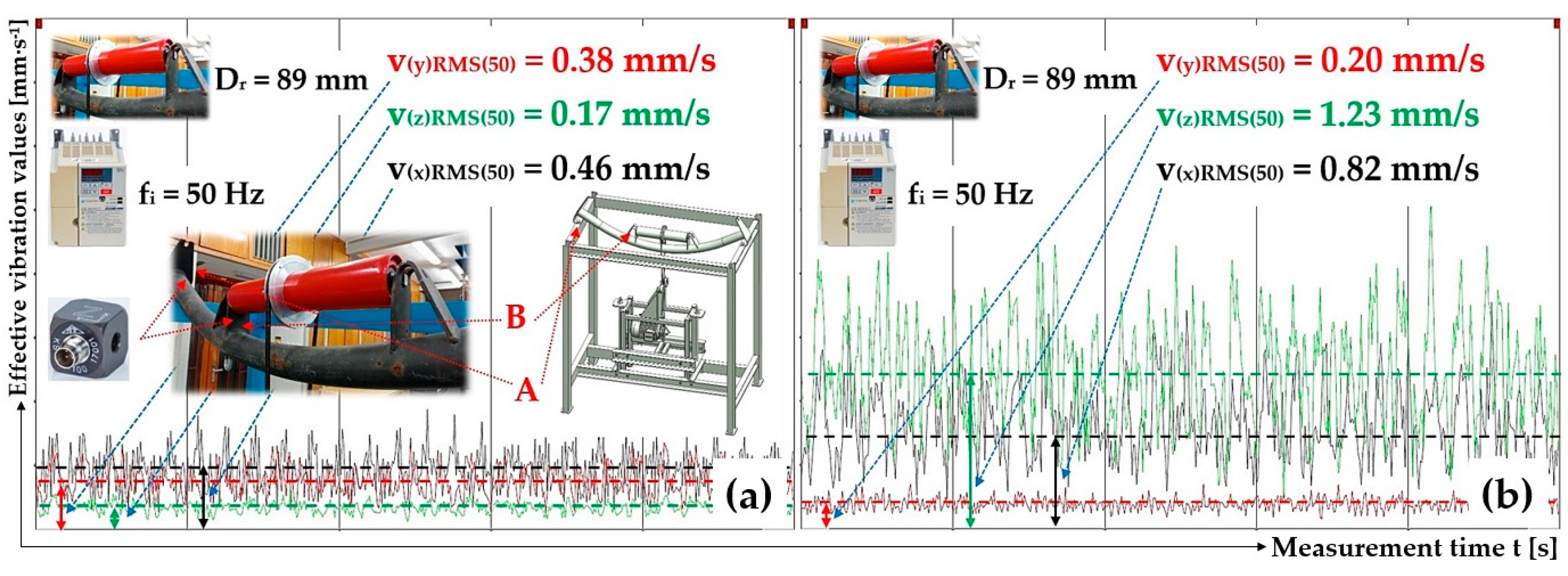
Effective vibration values v(*)RMS(fi) [mm·s-1], plastic roller ϕ89 mm, the circumferential speed of the roller vr = 3.84 m·s-1, plastic trestle, (a) measuring point A, (b) measuring point B.
Figure 12.
Effective vibration values v(*)RMS(fi) [mm·s-1], plastic roller ϕ89 mm, the circumferential speed of the roller vr = 3.84 m·s-1, plastic trestle, (a) measuring point A, (b) measuring point B.
Figure 13.
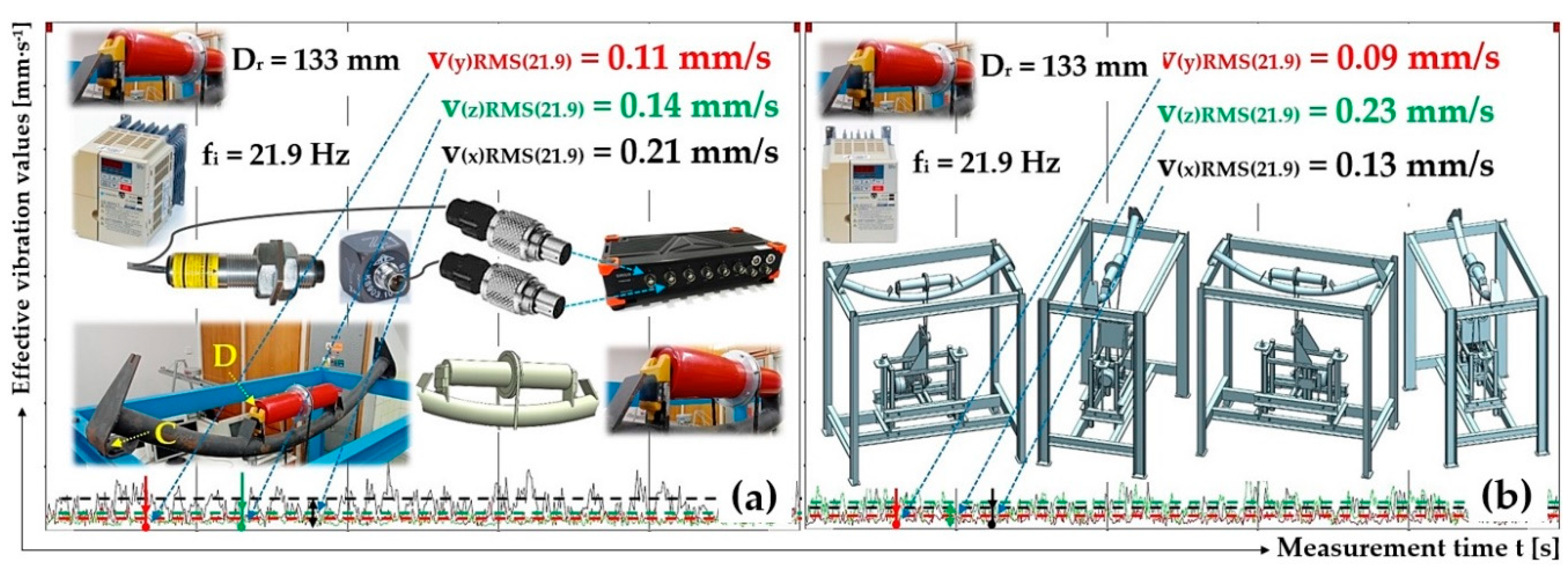
Effective vibration values v(*)RMS(fi) [mm·s-1], plastic roller ϕ89 mm, the circumferential speed of the roller vr = 3.84 m·s-1, plastic trestle, (a) measuring point C, (b) measuring point D.
Figure 13.
Effective vibration values v(*)RMS(fi) [mm·s-1], plastic roller ϕ89 mm, the circumferential speed of the roller vr = 3.84 m·s-1, plastic trestle, (a) measuring point C, (b) measuring point D.
Figure 14.
Effective vibration values v(*)RMS(fi) [mm·s-1], plastic roller ϕ108 mm, the circumferential speed of the roller vr = 2.5 m·s-1, plastic trestle, (a) measuring point A, (b) measuring point B.
Figure 14.
Effective vibration values v(*)RMS(fi) [mm·s-1], plastic roller ϕ108 mm, the circumferential speed of the roller vr = 2.5 m·s-1, plastic trestle, (a) measuring point A, (b) measuring point B.
Figure 15.
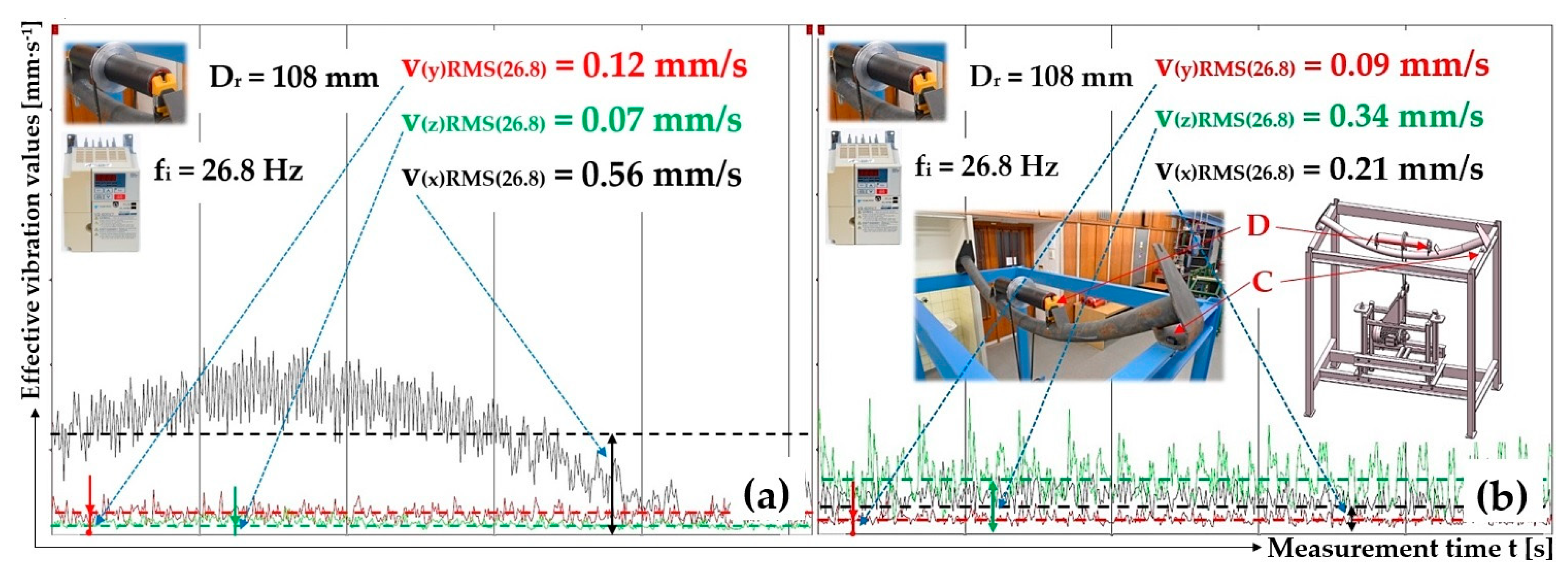
Effective vibration values v(*)RMS(fi) [mm·s-1], plastic roller ϕ108 mm, the circumferential speed of the roller vr = 2.5 m·s-1, plastic trestle, (a) measuring point C, (b) measuring point D.
Figure 15.
Effective vibration values v(*)RMS(fi) [mm·s-1], plastic roller ϕ108 mm, the circumferential speed of the roller vr = 2.5 m·s-1, plastic trestle, (a) measuring point C, (b) measuring point D.
Figure 16.
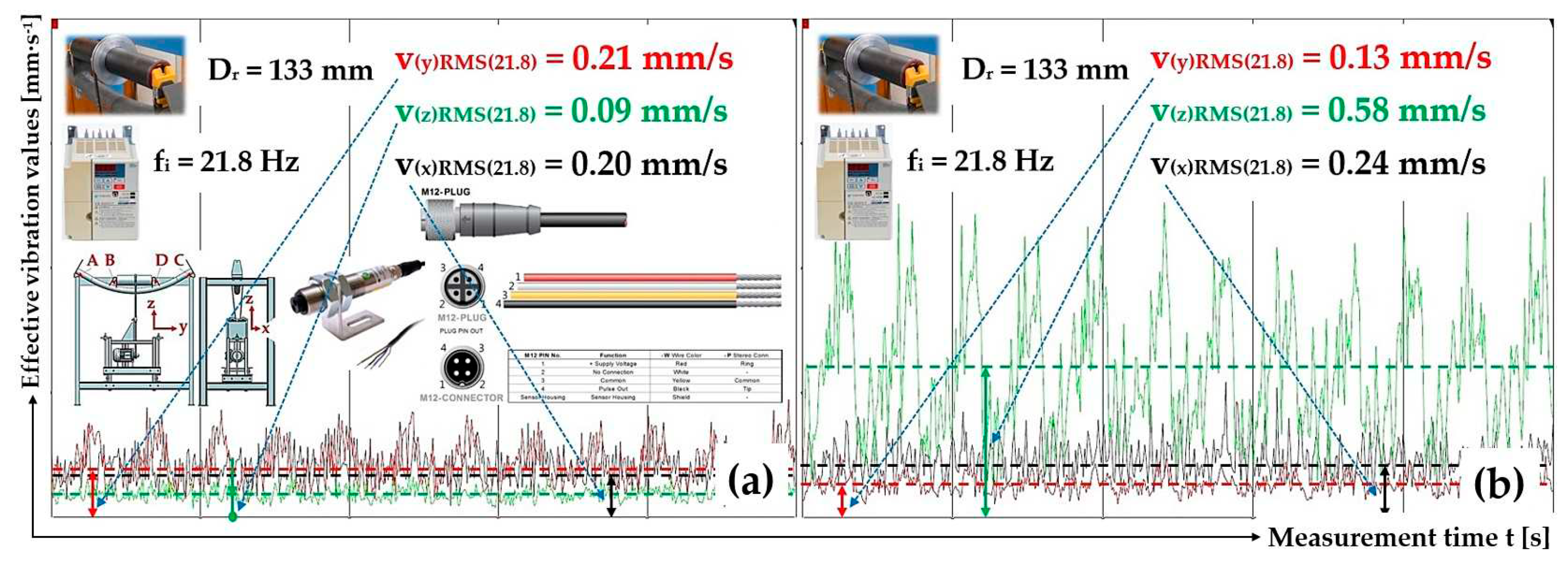
Effective vibration values v(*)RMS(fi) [mm·s-1], plastic roller ϕ133 mm, the circumferential speed of the roller vr = 2.5 m·s-1, plastic trestle, (a) measuring point A, (b) measuring point B.
Figure 16.
Effective vibration values v(*)RMS(fi) [mm·s-1], plastic roller ϕ133 mm, the circumferential speed of the roller vr = 2.5 m·s-1, plastic trestle, (a) measuring point A, (b) measuring point B.
Figure 17.
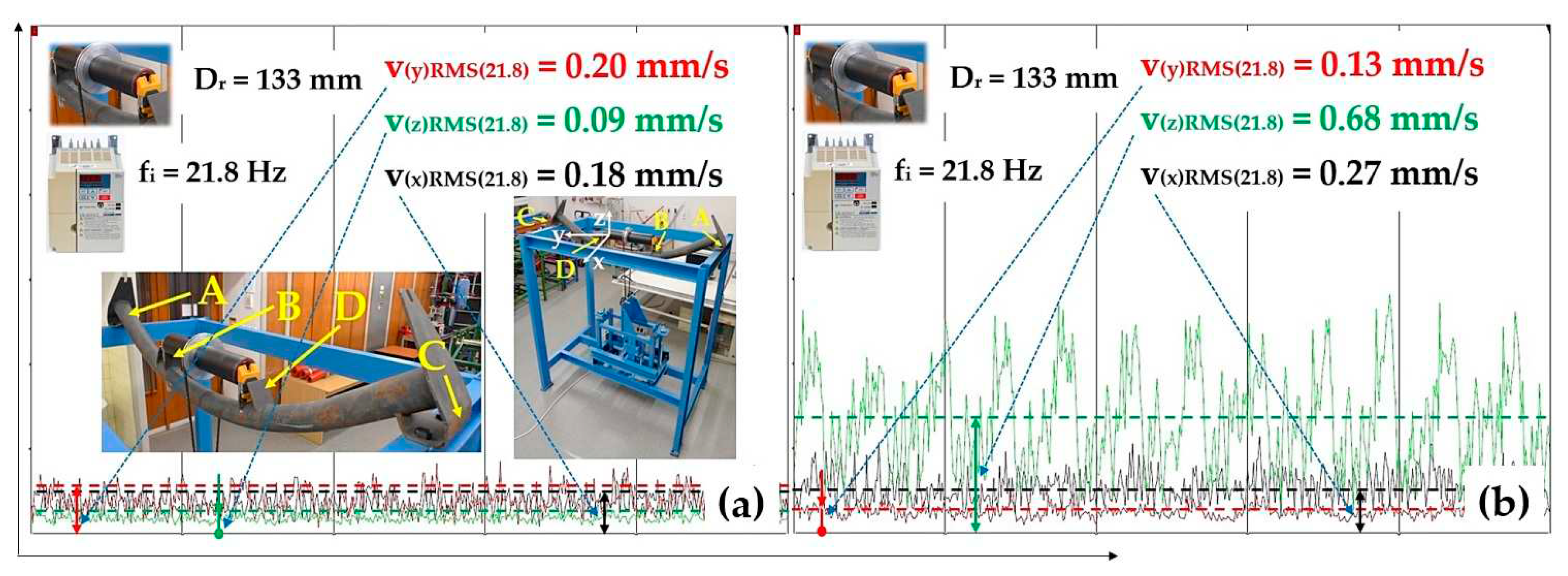
Effective vibration values v(*)RMS(fi) [mm·s-1], plastic roller ϕ133 mm, the circumferential speed of the roller vr = 2.5 m·s-1, plastic trestle, (a) measuring point C, (b) measuring point D.
Figure 17.
Effective vibration values v(*)RMS(fi) [mm·s-1], plastic roller ϕ133 mm, the circumferential speed of the roller vr = 2.5 m·s-1, plastic trestle, (a) measuring point C, (b) measuring point D.
Figure 18.
Effective vibration values v(*)RMS(fi) [mm·s-1], stell roller ϕ89 mm, the circumferential speed of the roller vr = 3.84 m·s-1, plastic trestle, (a) measuring point A, (b) measuring point B.
Figure 18.
Effective vibration values v(*)RMS(fi) [mm·s-1], stell roller ϕ89 mm, the circumferential speed of the roller vr = 3.84 m·s-1, plastic trestle, (a) measuring point A, (b) measuring point B.
Figure 19.
Effective vibration values v(*)RMS(fi) [mm·s-1], stell roller ϕ89 mm, the circumferential speed of the roller vr = 3.84 m·s-1, plastic trestle, (a) measuring point C, (b) measuring point D.
Figure 19.
Effective vibration values v(*)RMS(fi) [mm·s-1], stell roller ϕ89 mm, the circumferential speed of the roller vr = 3.84 m·s-1, plastic trestle, (a) measuring point C, (b) measuring point D.
Figure 20.
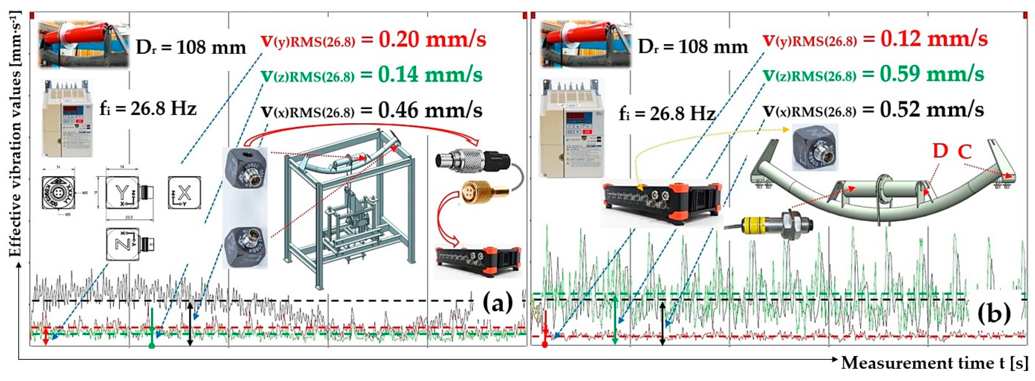
Effective vibration values v(*)RMS(fi) [mm·s-1], stell roller ϕ108 mm, the circumferential speed of the roller vr = 2.5 m·s-1, plastic trestle, (a) measuring point A, (b) measuring point B.
Figure 20.
Effective vibration values v(*)RMS(fi) [mm·s-1], stell roller ϕ108 mm, the circumferential speed of the roller vr = 2.5 m·s-1, plastic trestle, (a) measuring point A, (b) measuring point B.
Figure 21.
Effective vibration values v(*)RMS(fi) [mm·s-1], stell roller ϕ108 mm, the circumferential speed of the roller vr = 2.5 m·s-1, plastic trestle, (a) measuring point C, (b) measuring point D.
Figure 21.
Effective vibration values v(*)RMS(fi) [mm·s-1], stell roller ϕ108 mm, the circumferential speed of the roller vr = 2.5 m·s-1, plastic trestle, (a) measuring point C, (b) measuring point D.
Figure 22.
Effective vibration values v(*)RMS(fi) [mm·s-1], stell roller ϕ133 mm, the circumferential speed of the roller vr = 2.5 m·s-1, plastic trestle, (a) measuring point A, (b) measuring point B.
Figure 22.
Effective vibration values v(*)RMS(fi) [mm·s-1], stell roller ϕ133 mm, the circumferential speed of the roller vr = 2.5 m·s-1, plastic trestle, (a) measuring point A, (b) measuring point B.
Figure 23.
Effective vibration values v(*)RMS(fi) [mm·s-1], stell roller ϕ133 mm, the circumferential speed of the roller vr = 2.5 m·s-1, plastic trestle, (a) measuring point C, (b) measuring point D.
Figure 23.
Effective vibration values v(*)RMS(fi) [mm·s-1], stell roller ϕ133 mm, the circumferential speed of the roller vr = 2.5 m·s-1, plastic trestle, (a) measuring point C, (b) measuring point D.
Figure 24.
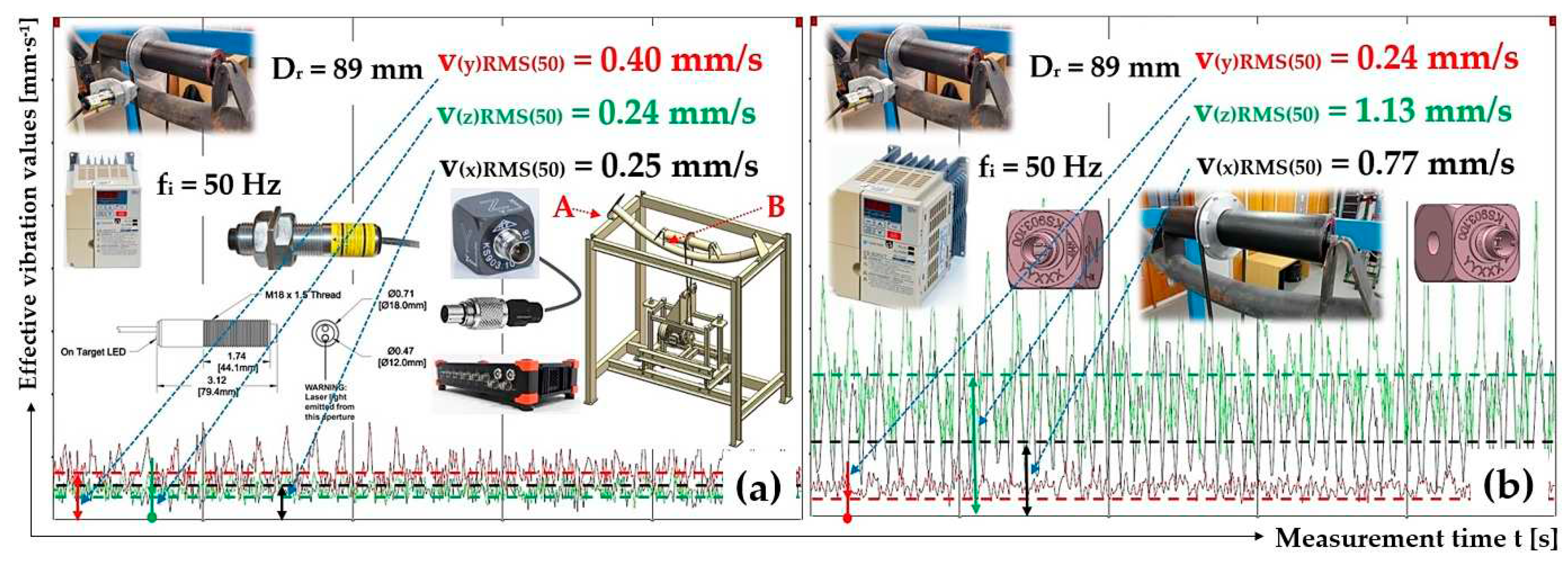
Effective vibration values v(*)RMS(fi) [mm·s-1], plastic roller ϕ89 mm, the circumferential speed of the roller vr = 3.85 m·s-1, steel trestle, (a) measuring point A, (b) measuring point B.
Figure 24.
Effective vibration values v(*)RMS(fi) [mm·s-1], plastic roller ϕ89 mm, the circumferential speed of the roller vr = 3.85 m·s-1, steel trestle, (a) measuring point A, (b) measuring point B.
Figure 25.
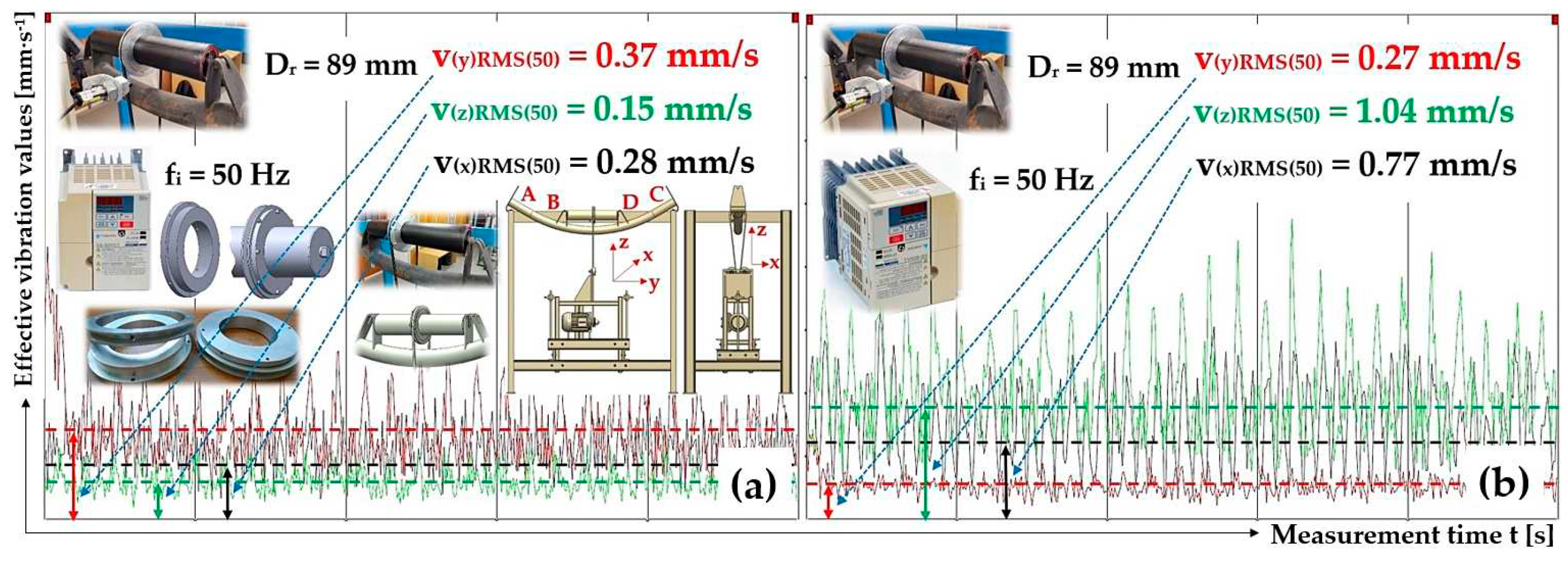
Effective vibration values v(*)RMS(fi) [mm·s-1], plastic roller ϕ89 mm, the circumferential speed of the roller vr = 3.85 m·s-1, steel trestle, (a) measuring point C, (b) measuring point D.
Figure 25.
Effective vibration values v(*)RMS(fi) [mm·s-1], plastic roller ϕ89 mm, the circumferential speed of the roller vr = 3.85 m·s-1, steel trestle, (a) measuring point C, (b) measuring point D.
Figure 26.
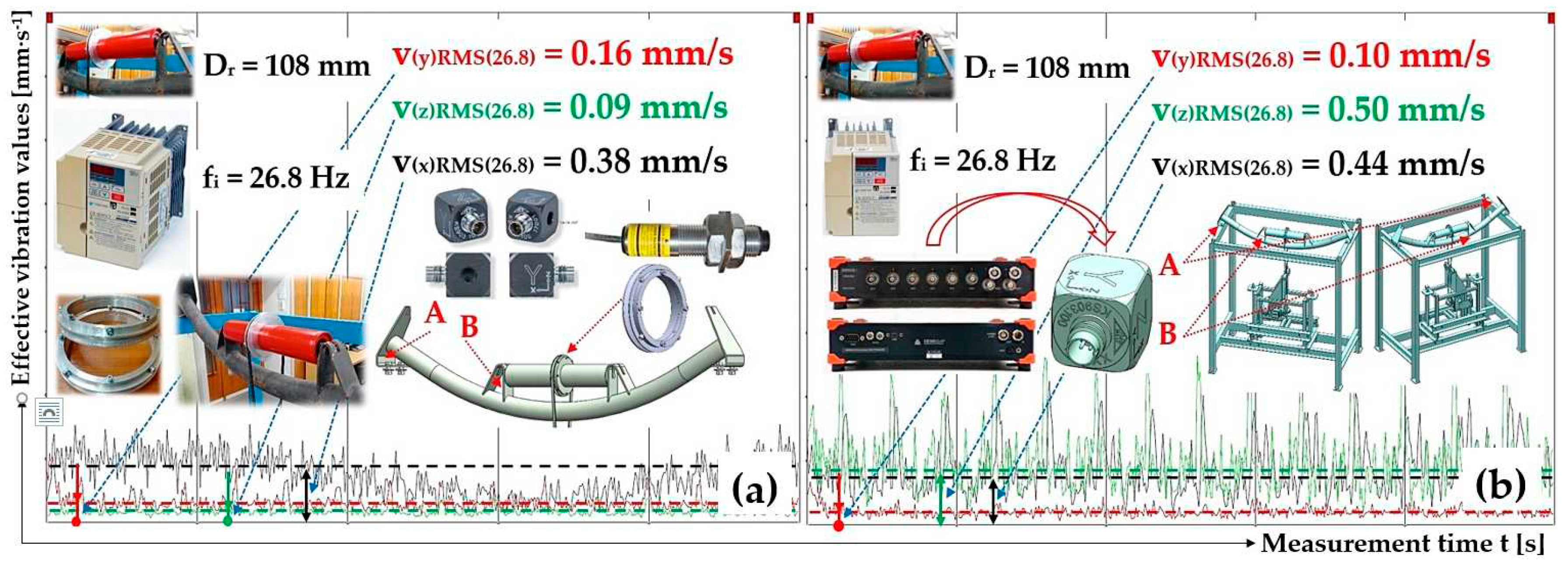
Effective vibration values v(*)RMS(fi) [mm·s-1], plastic roller ϕ108 mm, the circumferential speed of the roller vr = 2.5 m·s-1, steel trestle, (a) measuring point A, (b) measuring point B.
Figure 26.
Effective vibration values v(*)RMS(fi) [mm·s-1], plastic roller ϕ108 mm, the circumferential speed of the roller vr = 2.5 m·s-1, steel trestle, (a) measuring point A, (b) measuring point B.
Figure 27.
Effective vibration values v(*)RMS(fi) [mm·s-1], plastic roller ϕ108 mm, the circumferential speed of the roller vr = 2.5 m·s-1, steel trestle, (a) measuring point C, (b) measuring point D.
Figure 27.
Effective vibration values v(*)RMS(fi) [mm·s-1], plastic roller ϕ108 mm, the circumferential speed of the roller vr = 2.5 m·s-1, steel trestle, (a) measuring point C, (b) measuring point D.
Figure 28.
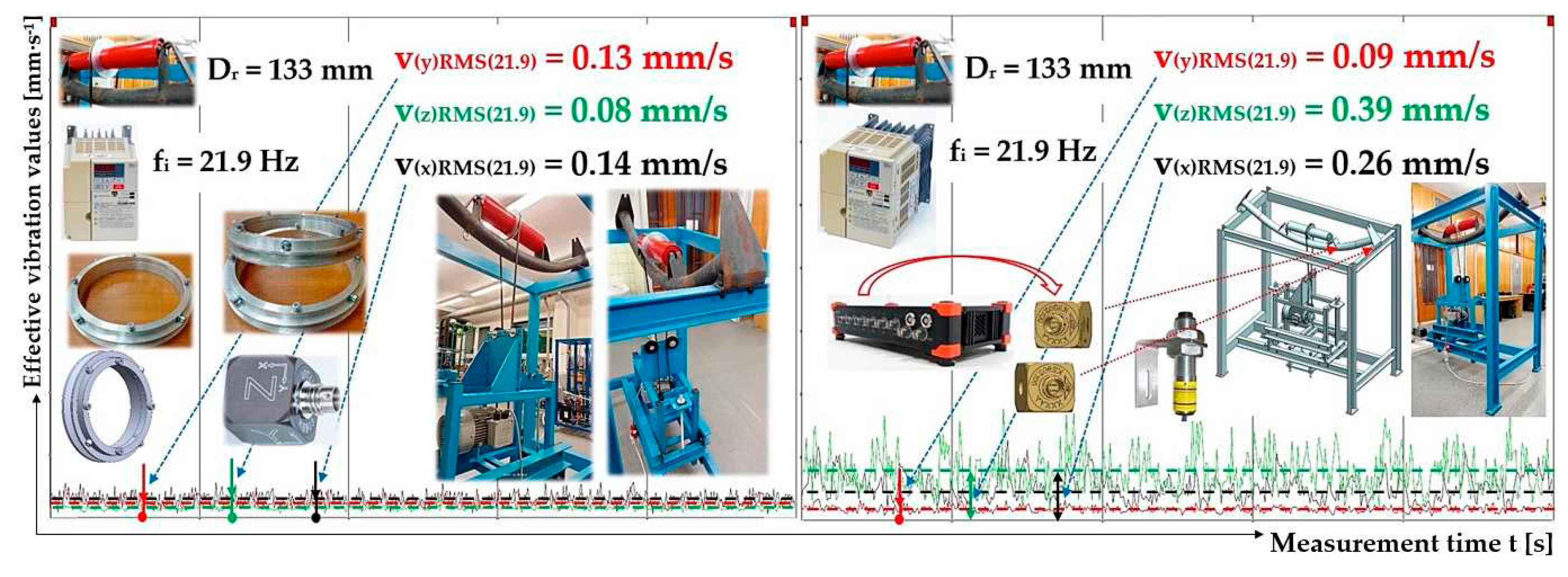
Effective vibration values v(*)RMS(fi) [mm·s-1], plastic roller ϕ133 mm, the circumferential speed of the roller vr = 2.5 m·s-1, steel trestle, (a) measuring point A, (b) measuring point B.
Figure 28.
Effective vibration values v(*)RMS(fi) [mm·s-1], plastic roller ϕ133 mm, the circumferential speed of the roller vr = 2.5 m·s-1, steel trestle, (a) measuring point A, (b) measuring point B.
Figure 29.
Effective vibration values v(*)RMS(fi) [mm·s-1], plastic roller ϕ133 mm, the circumferential speed of the roller vr = 2.5 m·s-1, steel trestle, (a) measuring point C, (b) measuring point D.
Figure 29.
Effective vibration values v(*)RMS(fi) [mm·s-1], plastic roller ϕ133 mm, the circumferential speed of the roller vr = 2.5 m·s-1, steel trestle, (a) measuring point C, (b) measuring point D.
Figure 30.
Effective vibration values v(*)RMS(fi) [mm·s-1], steel roller ϕ89 mm, the circumferential speed of the roller vr = 3.84 m·s-1, steel trestle, (a) measuring point A, (b) measuring point B.
Figure 30.
Effective vibration values v(*)RMS(fi) [mm·s-1], steel roller ϕ89 mm, the circumferential speed of the roller vr = 3.84 m·s-1, steel trestle, (a) measuring point A, (b) measuring point B.
Figure 31.
Effective vibration values v(*)RMS(fi) [mm·s-1], steel roller ϕ89 mm, the circumferential speed of the roller vr = 3.85 m·s-1, steel trestle, (a) measuring point C, (b) measuring point D.
Figure 31.
Effective vibration values v(*)RMS(fi) [mm·s-1], steel roller ϕ89 mm, the circumferential speed of the roller vr = 3.85 m·s-1, steel trestle, (a) measuring point C, (b) measuring point D.
Figure 32.
Effective vibration values v(*)RMS(fi) [mm·s-1], steel roller ϕ108 mm, the circumferential speed of the roller vr = 2.5 m·s-1, steel trestle, (a) measuring point A, (b) measuring point B.
Figure 32.
Effective vibration values v(*)RMS(fi) [mm·s-1], steel roller ϕ108 mm, the circumferential speed of the roller vr = 2.5 m·s-1, steel trestle, (a) measuring point A, (b) measuring point B.
Figure 33.
Effective vibration values v(*)RMS(fi) [mm·s-1], steel roller ϕ108 mm, the circumferential speed of the roller vr = 2.5 m·s-1, steel trestle, (a) measuring point C, (b) measuring point D.
Figure 33.
Effective vibration values v(*)RMS(fi) [mm·s-1], steel roller ϕ108 mm, the circumferential speed of the roller vr = 2.5 m·s-1, steel trestle, (a) measuring point C, (b) measuring point D.
Figure 34.
Effective vibration values v(*)RMS(fi) [mm·s-1], steel roller ϕ133 mm, the circumferential speed of the roller vr = 2.5 m·s-1, steel trestle, (a) measuring point A, (b) measuring point B.
Figure 34.
Effective vibration values v(*)RMS(fi) [mm·s-1], steel roller ϕ133 mm, the circumferential speed of the roller vr = 2.5 m·s-1, steel trestle, (a) measuring point A, (b) measuring point B.
Figure 35.
Effective vibration values v(*)RMS(fi) [mm·s-1], steel roller ϕ133 mm, the circumferential speed of the roller vr = 2.5 m·s-1, steel trestle, (a) measuring point C, (b) measuring point D.
Figure 35.
Effective vibration values v(*)RMS(fi) [mm·s-1], steel roller ϕ133 mm, the circumferential speed of the roller vr = 2.5 m·s-1, steel trestle, (a) measuring point C, (b) measuring point D.
Figure 36.
The effective vibration values v
(*)RMS(fi) [mm·s
-1] of conveyor rollers with a 89 mm diameter, at revolutions 825 min
-1. Measuring point as in
Figure 11 (a) A, (b) C, (c) B, (d) D.
Figure 36.
The effective vibration values v
(*)RMS(fi) [mm·s
-1] of conveyor rollers with a 89 mm diameter, at revolutions 825 min
-1. Measuring point as in
Figure 11 (a) A, (b) C, (c) B, (d) D.
Figure 37.
The effective vibration values v
(*)RMS(fi) [mm·s
-1] of conveyor rollers with a 108 mm diameter, at revolutions 442 min
-1. Measuring point as in
Figure 11 (a) A, (b) C, (c) B, (d) D.
Figure 37.
The effective vibration values v
(*)RMS(fi) [mm·s
-1] of conveyor rollers with a 108 mm diameter, at revolutions 442 min
-1. Measuring point as in
Figure 11 (a) A, (b) C, (c) B, (d) D.
Figure 38.
The effective vibration values v
(*)RMS(fi) [mm·s
-1] of conveyor rollers with a 133 mm diameter, at revolutions 361 min
-1. Measuring point as in
Figure 11 (a) A, (b) C, (c) B, (d) D.
Figure 38.
The effective vibration values v
(*)RMS(fi) [mm·s
-1] of conveyor rollers with a 133 mm diameter, at revolutions 361 min
-1. Measuring point as in
Figure 11 (a) A, (b) C, (c) B, (d) D.
Figure 39.
The effective vibration values v
(*)RMS(fi) [mm·s
-1] of ϕ133 mm conveyor rollers at different revolutions. Measuring point as in
Figure 11 (a) B, (b) D, (c) A, (d) C.
Figure 39.
The effective vibration values v
(*)RMS(fi) [mm·s
-1] of ϕ133 mm conveyor rollers at different revolutions. Measuring point as in
Figure 11 (a) B, (b) D, (c) A, (d) C.
Figure 40.
The effective vibration values v
(*)RMS(fi) [mm·s
-1] of ϕ108 mm conveyor rollers at different revolutions. Measuring point as in
Figure 11 (a) B, (b) D, (c) A, (d) C.
Figure 40.
The effective vibration values v
(*)RMS(fi) [mm·s
-1] of ϕ108 mm conveyor rollers at different revolutions. Measuring point as in
Figure 11 (a) B, (b) D, (c) A, (d) C.
Figure 41.
The effective vibration values v
(*)RMS(fi) [mm·s
-1] of ϕ89 mm conveyor rollers at different revolutions. Measuring point as in
Figure 11 (a) B, (b) D, (c) A, (d) C.
Figure 41.
The effective vibration values v
(*)RMS(fi) [mm·s
-1] of ϕ89 mm conveyor rollers at different revolutions. Measuring point as in
Figure 11 (a) B, (b) D, (c) A, (d) C.
Table 1.
Calculated values of the rotational speed nr [min-1] of a conveyor roller with a given diameter Dr [m] for circumferential speed vr [m·s-1] of the conveyor roller casings.
Table 1.
Calculated values of the rotational speed nr [min-1] of a conveyor roller with a given diameter Dr [m] for circumferential speed vr [m·s-1] of the conveyor roller casings.
| Dr [mm] |
89 |
108 |
133 |
fi
[Hz] |
vr
[m·s-1] |
nr
[s-1] |
nr
[min-1] |
fi
[Hz] |
vr
[m·s-1] |
nr
[s-1] |
nr
[min-1] |
fi
[Hz] |
vr
[m·s-1] |
nr
[s-1] |
nr
[min-1] |
| 50 |
3.58 |
12.81 |
768.7 |
50 |
4.35 |
12.82 |
769.2 |
50 |
5.35 |
12.80 |
768.3 |
| 34.9 |
2.5 |
8.94 |
536.5 |
41.2 |
3.58 |
10.55 |
633.1 |
33.4 |
3.58 |
10.41 |
624.7 |
| 17.4 |
1.25 |
4.47 |
268.2 |
28.8 |
2.5 |
7.37 |
442.1 |
23.4 |
2.5 |
5.98 |
359.0 |
| - |
- |
- |
- |
14.4 |
1.25 |
3.68 |
221.0 |
11.7 |
1.25 |
2.99 |
179.5 |
Table 2.
Basic dimensions of the conveyor idler according to [
52].
Table 2.
Basic dimensions of the conveyor idler according to [
52].
| |
E |
D = Dr
|
L |
a |
b |
t |
o |
s |
h |
f |
α |
weight |
| [mm] |
[deg] |
[kg] |
| 1200 |
1600 |
89, 108, 133 |
465 |
35 |
140 |
100 |
18 |
14 |
85 |
175 |
20 |
18.5 |
Table 3.
Roller axle placement—plastic trestle, measuring points A and B, roller casing—plastic, Dr = 89 mm.
Table 3.
Roller axle placement—plastic trestle, measuring points A and B, roller casing—plastic, Dr = 89 mm.
| fi
|
nr
|
vr
|
Measuring point „A“ |
Measuring point „B“ |
| v(x)RMS(fi)
|
v(y)RMS(fi)
|
v(z)RMS(fi)
|
v(x)RMS(fi)
|
v(y)RMS(fi)
|
v(z)RMS(fi)
|
| [Hz] |
[min-1] |
[m·s-1] |
[mm·s-1] |
[mm·s-1] |
| 50 |
825 |
3.84 |
0.93 1
|
0.31 1
|
0.21 1
|
0.47 2
|
0.17 2
|
0.92 2
|
| 32.5 |
536 |
2.50 |
0.23 |
0.21 |
0.10 |
0.52 |
0.14 |
0.62 |
| 16.2 |
268 |
1.25 |
0.14 |
0.10 |
0.07 |
0.14 |
0.08 |
0.22 |
Table 4.
Roller axle placement—plastic trestle, measuring points C and D, roller casing—plastic, Dr = 89 mm.
Table 4.
Roller axle placement—plastic trestle, measuring points C and D, roller casing—plastic, Dr = 89 mm.
| fi
|
nr
|
vr
|
Measuring point „C“ |
Measuring point „D“ |
| v(x)RMS(fi)
|
v(y)RMS(fi)
|
v(z)RMS(fi)
|
v(x)RMS(fi)
|
v(y)RMS(fi)
|
v(z)RMS(fi)
|
| [Hz] |
[min-1] |
[m·s-1] |
[mm·s-1] |
[mm·s-1] |
| 50 |
825 |
3.84 |
0.87 1
|
0.25 1
|
0.13 1
|
0.40 2
|
0.14 2
|
0.93 2
|
| 32.4 |
535 |
2.49 |
1.61 |
0.20 |
0.12 |
1.03 |
0.12 |
0.65 |
| 16.2 |
267 |
1.25 |
0.12 |
0.12 |
0.08 |
0.26 |
0.06 |
0.23 |
Table 5.
Roller axle placement—plastic trestle, measuring points A and B, roller casing—plastic, Dr = 108 mm.
Table 5.
Roller axle placement—plastic trestle, measuring points A and B, roller casing—plastic, Dr = 108 mm.
| fi
|
nr
|
vr
|
Measuring point “A” |
Measuring point “B” |
| v(x)RMS(fi)
|
v(y)RMS(fi)
|
v(z)RMS(fi)
|
v(x)RMS(fi)
|
v(y)RMS(fi)
|
v(z)RMS(fi)
|
| [Hz] |
[min-1] |
[m·s-1] |
[mm·s-1] |
| 50 |
824 |
4.66 |
0.92 |
0.26 |
0.25 |
0.46 |
0.22 |
0.70 |
| 41.3 |
681 |
3.85 |
0.88 |
0.36 |
0.22 |
0.53 |
0.29 |
1.03 |
| 26.8 |
442 |
2.5 |
0.60 1
|
0.14 1
|
0.13 1
|
0.25 2
|
0.10 2
|
0.34 2
|
| 13.4 |
220 |
1.24 |
0.09 |
0.08 |
0.06 |
0.08 |
0.05 |
0.17 |
Table 6.
Roller axle placement—plastic trestle, measuring points C and D, roller casing—plastic, Dr = 108 mm.
Table 6.
Roller axle placement—plastic trestle, measuring points C and D, roller casing—plastic, Dr = 108 mm.
| fi
|
nr
|
vr
|
Measuring point „C“ |
Measuring point „D“ |
| v(x)RMS(fi)
|
v(y)RMS(fi)
|
v(z)RMS(fi)
|
v(x)RMS(fi)
|
v(y)RMS(fi)
|
v(z)RMS(fi)
|
| [Hz] |
[min-1] |
[m·s-1] |
[mm·s-1] |
| 50 |
824 |
4.66 |
0.55 |
0.23 |
0.11 |
0.36 |
0.21 |
0.72 |
| 41.3 |
681 |
3.85 |
0.52 |
0.33 |
0.09 |
0.41 |
0.26 |
0.96 |
| 26.8 |
442 |
2.5 |
0.56 1
|
0.12 1
|
0.07 1
|
0.21 2
|
0.09 2
|
0.34 2
|
| 13.4 |
220 |
1.24 |
0.11 |
0.06 |
0.06 |
0.09 |
0.10 |
0.15 |
Table 7.
Roller axle placement—plastic trestle, measuring points A and B, roller casing—plastic, Dr = 133 mm.
Table 7.
Roller axle placement—plastic trestle, measuring points A and B, roller casing—plastic, Dr = 133 mm.
| fi
|
nr
|
vr
|
Measuring point „A“ |
Measuring point „B“ |
| v(x)RMS(fi)
|
v(y)RMS(fi)
|
v(z)RMS(fi)
|
v(x)RMS(fi)
|
v(y)RMS(fi)
|
v(z)RMS(fi)
|
| [Hz] |
[min-1] |
[m·s-1] |
[mm·s-1] |
| 50 |
824 |
5.74 |
0.70 |
0.37 |
0.21 |
0.51 |
0.29 |
0.89 |
| 33.7 |
555 |
3.86 |
0.46 |
0.36 |
0.15 |
0.50 |
0.28 |
0.85 |
| 21.8 |
360 |
2.51 |
0.20 1
|
0.21 1
|
0.09 1
|
0.24 2
|
0.13 2
|
0.58 2
|
| 10.9 |
179 |
1.25 |
0.07 |
0.11 |
0.06 |
0.10 |
0.08 |
0.18 |
Table 8.
Roller axle placement—plastic trestle, measuring points C and D, roller casing—plastic, Dr = 133 mm.
Table 8.
Roller axle placement—plastic trestle, measuring points C and D, roller casing—plastic, Dr = 133 mm.
| fi
|
nr
|
vr
|
Measuring point „C“ |
Measuring point „D“ |
| v(x)RMS(fi)
|
v(y)RMS(fi)
|
v(z)RMS(fi)
|
v(x)RMS(fi)
|
v(y)RMS(fi)
|
v(z)RMS(fi)
|
| [Hz] |
[min-1] |
[m·s-1] |
[mm·s-1] |
| 50 |
825 |
5.75 |
0.46 |
0.46 |
0.19 |
0.66 |
0.43 |
1.11 |
| 33.7 |
555 |
3.86 |
0.73 |
0.35 |
0.11 |
0.55 |
0.34 |
0.88 |
| 21.8 |
360 |
2.50 |
0.18 1
|
0.20 1
|
0.09 1
|
0.27 2
|
0.13 2
|
0.68 2
|
| 10.9 |
179 |
1.25 |
0.08 |
0.09 |
0.06 |
0.10 |
0.08 |
0.19 |
Table 9.
Roller axles placement—plastic trestle, measuring points A and B, roller casing—steel, Dr = 89 mm.
Table 9.
Roller axles placement—plastic trestle, measuring points A and B, roller casing—steel, Dr = 89 mm.
| fi
|
nr
|
vr
|
Measuring point “A” |
Measuring point “B” |
| v(x)RMS(fi)
|
v(y)RMS(fi)
|
v(z)RMS(fi)
|
v(x)RMS(fi)
|
v(y)RMS(fi)
|
v(z)RMS(fi)
|
| [Hz] |
[min-1] |
[m·s-1] |
[mm·s-1] |
| 50 |
823 |
3.84 |
0.54 1
|
0.20 1
|
0.11 1
|
0.33 2
|
0.36 2
|
0.46 2
|
| 32.3 |
533 |
2.48 |
1.93 |
0.46 |
0.16 |
1.32 |
0.60 |
0.56 |
| 16.1 |
266 |
1.24 |
0.22 |
0.10 |
0.08 |
0.24 |
0.12 |
0.21 |
Table 10.
Roller axles placement—plastic trestle, measuring points C and D, roller casing—steel, Dr = 89 mm.
Table 10.
Roller axles placement—plastic trestle, measuring points C and D, roller casing—steel, Dr = 89 mm.
| fi
|
nr
|
vr
|
Measuring point “C” |
Measuring point „D“ |
| v(x)RMS(fi)
|
v(y)RMS(fi)
|
v(z)RMS(fi)
|
v(x)RMS(fi)
|
v(y)RMS(fi)
|
v(z)RMS(fi)
|
| [Hz] |
[min-1] |
[m·s-1] |
[mm·s-1] |
| 50 |
823 |
3.84 |
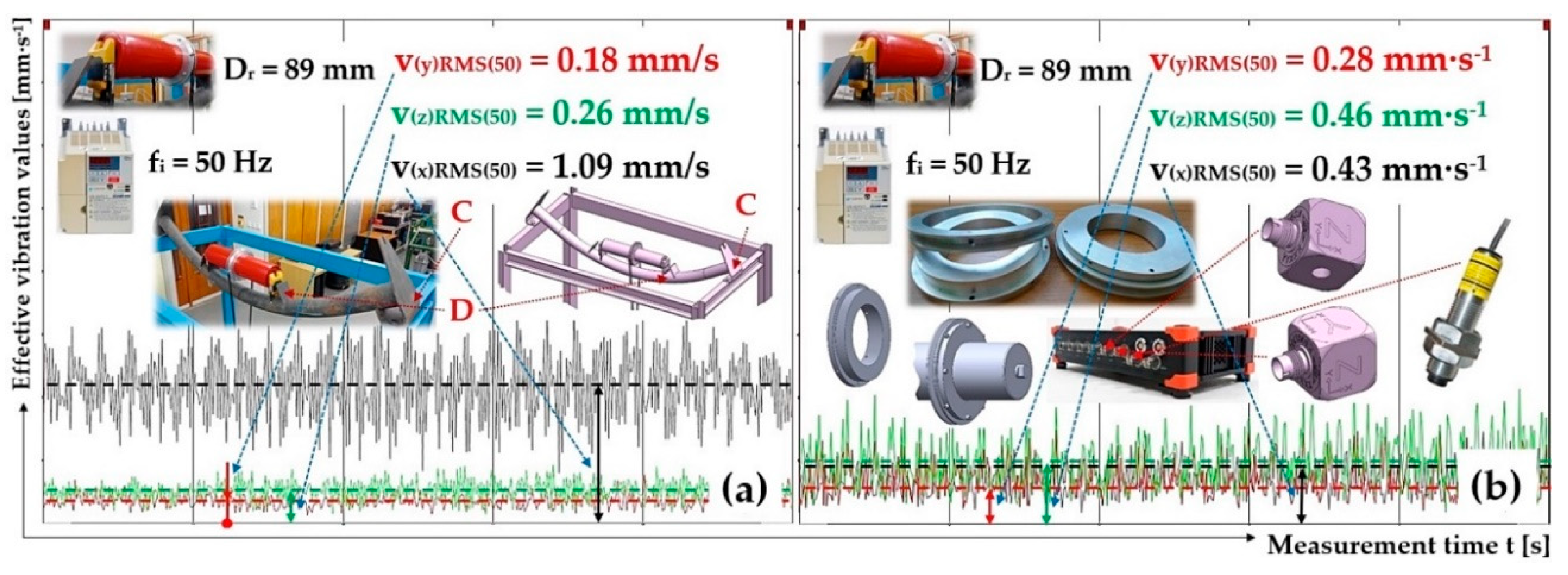
1.09 1
|
0.18 1
|
0.26 1
|
0.43 2
|
0.28 2
|
0.46 2
|
| 32.3 |
533 |
2.48 |
0.81 |
0.51 |
0.22 |
0.70 |
0.52 |
0.52 |
| 16.12 |
266 |
1.24 |
0.17 |
0.10 |
0.09 |
0.11 |
0.07 |
0.18 |
Table 11.
Roller axles placement—plastic trestle, measuring points A and B, roller casing—steel, Dr = 108 mm.
Table 11.
Roller axles placement—plastic trestle, measuring points A and B, roller casing—steel, Dr = 108 mm.
| fi
|
nr
|
vr
|
Measuring point “A” |
Measuring point “B” |
| v(x)RMS(fi)
|
v(y)RMS(fi)
|
v(z)RMS(fi)
|
v(x)RMS(fi)
|
v(y)RMS(fi)
|
v(z)RMS(fi)
|
| [Hz] |
[min-1] |
[m·s-1] |
[mm·s-1] |
| 50 |
826 |
4.67 |
0.75 |
0.24 |
0.15 |
0.39 |
0.19 |
0.48 |
| 41.4 |
682 |
3.86 |
0.36 |
0.31 |
0.12 |
0.32 |
0.18 |
0.56 |
| 26.84 |
442 |
2.5 |
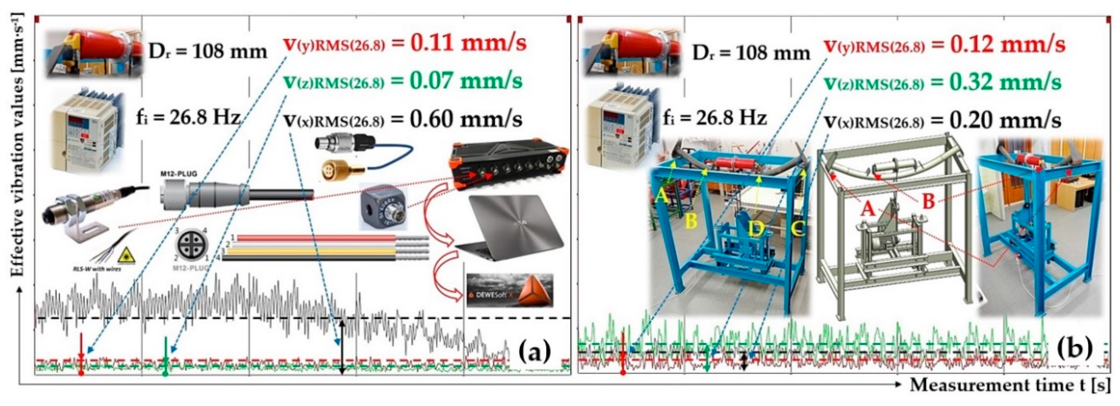
0.60 1
|
0.11 1
|
0.07 1
|
0.20 2
|
0.12 2
|
0.32 2
|
| 13.36 |
220 |
1.25 |
0.12 |
0.08 |
0.08 |
0.10 |
0.08 |
0.14 |
Table 12.
Roller axles placement—plastic trestle, measuring points C and D, roller casing—steel, Dr = 108 mm.
Table 12.
Roller axles placement—plastic trestle, measuring points C and D, roller casing—steel, Dr = 108 mm.
| fi
|
nr
|
vr
|
Measuring point “C” |
Measuring point “D” |
| v(x)RMS(fi)
|
v(y)RMS(fi)
|
v(z)RMS(fi)
|
v(x)RMS(fi)
|
v(y)RMS(fi)
|
v(z)RMS(fi)
|
| [Hz] |
[min-1] |
[m·s-1] |
[mm·s-1] |
| 50 |
826 |
4.67 |
1.40 |
0.20 |
0.31 |
0.38 |
0.19 |
0.44 |
| 41.34 |
681 |
3.85 |
1.27 |
0.25 |
0.28 |
0.61 |
0.19 |
0.52 |
| 26.85 |
443 |
2.5 |
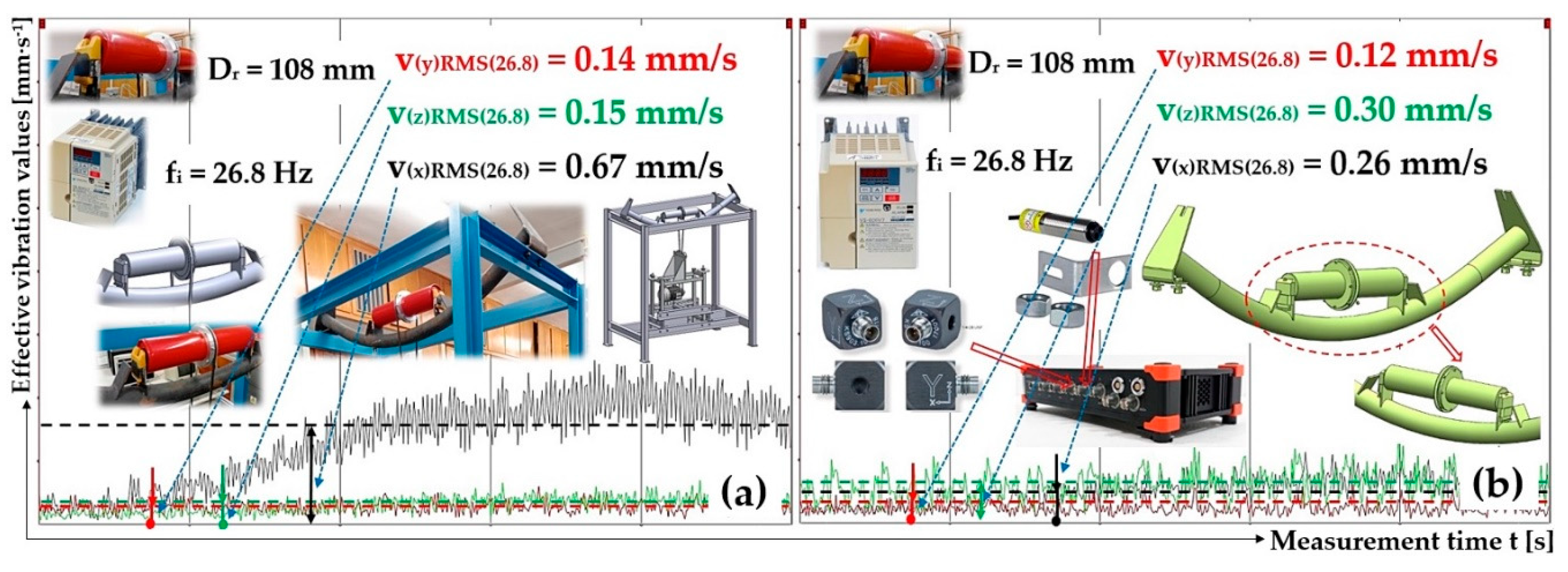
0.67 1
|
0.14 1
|
0.15 1
|
0.26 2
|
0.12 2
|
0.30 2
|
| 13.37 |
220 |
1.25 |
0.11 |
0.12 |
0.09 |
0.08 |
0.07 |
0.13 |
Table 13.
Roller axles placement—plastic trestle, measuring points A and B, roller casing—steel, Dr = 133 mm.
Table 13.
Roller axles placement—plastic trestle, measuring points A and B, roller casing—steel, Dr = 133 mm.
| fi
|
nr
|
vr
|
Measuring point “A” |
Measuring point “B” |
| v(x)RMS(fi)
|
v(y)RMS(fi)
|
v(z)RMS(fi)
|
v(x)RMS(fi)
|
v(y)RMS(fi)
|
v(z)RMS(fi)
|
| [Hz] |
[min-1] |
[m·s-1] |
[mm·s-1] |
| 50 |
825 |
5.75 |
0.47 |
0.24 |
0.11 |
0.35 |
0.24 |
0.55 |
| 33.64 |
554 |
3.86 |
0.64 |
0.17 |
0.10 |
0.48 |
0.18 |
0.37 |
| 21.92 |
361 |
2.52 |
0.23 1
|
0.12 1
|
0.07 1
|
0.21 2
|
0.13 2
|
0.26 2
|
| 10.89 |
179 |
1.25 |
0.19 |
0.09 |
0.07 |
0.14 |
0.09 |
0.16 |
Table 14.
Roller axles placement—plastic trestle, measuring points C and D, roller casing—steel, Dr = 133 mm.
Table 14.
Roller axles placement—plastic trestle, measuring points C and D, roller casing—steel, Dr = 133 mm.
| fi
|
nr
|
vr
|
Measuring point “C” |
Measuring point “D” |
| v(x)RMS(fi)
|
v(y)RMS(fi)
|
v(z)RMS(fi)
|
v(x)RMS(fi)
|
v(y)RMS(fi)
|
v(z)RMS(fi)
|
| [Hz] |
[min-1] |
[m·s-1] |
[mm·s-1] |
| 50 |
825 |
5.75 |
0.49 |
0.24 |
0.18 |
0.27 |
0.19 |
0.48 |
| 33.67 |
555 |
3.87 |
0.32 |
0.18 |
0.17 |
0.30 |
0.14 |
0.31 |
| 21.87 |
361 |
2.51 |
0.21 1
|
0.11 1
|
0.14 1
|
0.13 2
|
0.09 2
|
0.23 2
|
| 10.89 |
179 |
1.25 |
0.11 |
0.07 |
0.08 |
0.08 |
0.06 |
0.14 |
Table 15.
Roller axles placement—steel trestle, measuring points A and B, roller casing—plastic, Dr = 89 mm.
Table 15.
Roller axles placement—steel trestle, measuring points A and B, roller casing—plastic, Dr = 89 mm.
| fi
|
nr
|
vr
|
Measuring point „A“ |
Measuring point „B“ |
| v(x)RMS(fi)
|
v(y)RMS(fi)
|
v(z)RMS(fi)
|
v(x)RMS(fi)
|
v(y)RMS(fi)
|
v(z)RMS(fi)
|
| [Hz] |
[min-1] |
[m·s-1] |
[mm·s-1] |
[mm·s-1] |
| 50 |
824 |
3.84 |
0.25 1
|
0.40 1
|
0.24 1
|
0.77 2
|
0.24 2
|
1.13 2
|
| 32.33 |
533 |
2.48 |
0.92 |
0.25 |
0.17 |
1.02 |
0.14 |
0.81 |
| 16.14 |
266 |
1.24 |
0.09 |
0.14 |
0.15 |
0.28 |
0.13 |
0.32 |
Table 16.
Roller axles placement—steel trestle, measuring points C and D roller casing—plastic, Dr = 89 mm.
Table 16.
Roller axles placement—steel trestle, measuring points C and D roller casing—plastic, Dr = 89 mm.
| fi
|
nr
|
vr
|
Measuring point „C“ |
Measuring point „D“ |
| v(x)RMS(fi)
|
v(y)RMS(fi)
|
v(z)RMS(fi)
|
v(x)RMS(fi)
|
v(y)RMS(fi)
|
v(z)RMS(fi)
|
| [Hz] |
[min-1] |
[m·s-1] |
[mm·s-1] |
| 50 |
826 |
3.85 |
0.28 1
|
0.37 1
|
0.15 1
|
0.77 2
|
0.27 2
|
1.04 2
|
| 32.35 |
533 |
2.48 |
0.26 |
0.28 |
0.12 |
0.89 |
0.17 |
0.79 |
| 16.15 |
266 |
1.24 |
0.11 |
0.17 |
0.13 |
0.31 |
0.14 |
0.33 |
Table 17.
Roller axles placement—steel trestle, measuring points A and B roller casing—plastic, Dr = 108 mm.
Table 17.
Roller axles placement—steel trestle, measuring points A and B roller casing—plastic, Dr = 108 mm.
| fi
|
nr
|
vr
|
Measuring point „A“ |
Measuring point „B“ |
| v(x)RMS(fi)
|
v(y)RMS(fi)
|
v(z)RMS(fi)
|
v(x)RMS(fi)
|
v(y)RMS(fi)
|
v(z)RMS(fi)
|
| [Hz] |
[min-1] |
[m·s-1] |
[mm·s-1] |
| 50 |
825 |
4.66 |
0.44 |
0.53 |
0.36 |
0.66 |
0.32 |
2.16 |
| 41.24 |
680 |
3.84 |
0.28 |
0.41 |
0.22 |
0.76 |
0.32 |
1.33 |
| 26.73 |
441 |
2.50 |
0.33 1
|
0.26 1
|
0.14 1
|
0.78 2
|
0.20 2
|
0.81 2
|
| 13.34 |
220 |
1.24 |
0.08 |
0.13 |
0.06 |
0.17 |
0.10 |
0.32 |
Table 18.
Roller axles placement—steel trestle, measuring points C and D roller casing—plastic, Dr = 108 mm.
Table 18.
Roller axles placement—steel trestle, measuring points C and D roller casing—plastic, Dr = 108 mm.
| fi
|
nr
|
vr
|
Measuring point „C“ |
Measuring point „D“ |
| v(x)RMS(fi)
|
v(y)RMS(fi)
|
v(z)RMS(fi)
|
v(x)RMS(fi)
|
v(y)RMS(fi)
|
v(z)RMS(fi)
|
| [Hz] |
[min-1] |
[m·s-1] |
[mm·s-1] |
| 50 |
823 |
4.65 |
0.58 |
0.86 |
0.23 |
0.61 |
0.45 |
2.54 |
| 41.29 |
681 |
3.85 |
0.66 |
0.48 |
0.18 |
0.76 |
0.40 |
1.30 |
| 26.68 |
440 |
2.49 |
0.35 1
|
0.24 1
|
0.11 1
|
0.63 1
|
0.18 1
|
0.64 1
|
| 13.35 |
220 |
1.24 |
0.08 |
0.13 |
0.06 |
0.14 |
0.09 |
0.32 |
Table 19.
Roller axles placement—steel trestle, measuring points A and B roller casing—plastic, Dr = 133 mm.
Table 19.
Roller axles placement—steel trestle, measuring points A and B roller casing—plastic, Dr = 133 mm.
| fi
|
nr
|
vr
|
Measuring point „A“ |
Measuring point „B“ |
| v(x)RMS(fi)
|
v(y)RMS(fi)
|
v(z)RMS(fi)
|
v(x)RMS(fi)
|
v(y)RMS(fi)
|
v(z)RMS(fi)
|
| [Hz] |
[min-1] |
[m·s-1] |
[mm·s-1] |
| 50 |
825 |
5.75 |
0.44 |
0.66 |
0.41 |
0.76 |
0.41 |
2.31 |
| 33.48 |
552 |
3.84 |
0.46 |
0.43 |
0.20 |
0.57 |
0.38 |
0.97 |
| 21.83 |
360 |
2.51 |
0.13 1
|
0.25 1
|
0.14 1
|
0.35 2
|
0.21 2
|
0.61 2
|
| 10.84 |
179 |
1.24 |
0.08 |
0.12 |
0.09 |
0.16 |
0.09 |
0.20 |
Table 20.
Roller axles placement—steel trestle, measuring points C and D roller casing—plastic, Dr = 133 mm.
Table 20.
Roller axles placement—steel trestle, measuring points C and D roller casing—plastic, Dr = 133 mm.
| fi
|
nr
|
vr
|
Measuring point „C“ |
Measuring point „D“ |
| v(x)RMS(fi)
|
v(y)RMS(fi)
|
v(z)RMS(fi)
|
v(x)RMS(fi)
|
v(y)RMS(fi)
|
v(z)RMS(fi)
|
| [Hz] |
[min-1] |
[m·s-1] |
[mm·s-1] |
| 50 |
824 |
5.74 |
0.69 |
0.68 |
0.23 |
0.95 |
0.39 |
1.94 |
| 33.56 |
553 |
3.85 |
0.49 |
0.38 |
0.16 |
0.63 |
0.27 |
0.92 |
| 21.84 |
360 |
2.51 |
0.18 1
|
0.23 1
|
0.12 1
|
0.38 2
|
0.18 2
|
0.57 2
|
| 10.84 |
179 |
1.24 |
0.11 |
0.15 |
0.09 |
0.21 |
0.10 |
0.19 |
Table 21.
Roller axles placement—steel trestle, measuring points A and B roller casing—steel, Dr = 89 mm.
Table 21.
Roller axles placement—steel trestle, measuring points A and B roller casing—steel, Dr = 89 mm.
| fi
|
nr
|
vr
|
Measuring point „A“ |
Measuring point „B“ |
| v(x)RMS(fi)
|
v(y)RMS(fi)
|
v(z)RMS(fi)
|
v(x)RMS(fi)
|
v(y)RMS(fi)
|
v(z)RMS(fi)
|
| [Hz] |
[min-1] |
[m·s-1] |
[mm·s-1] |
[mm·s-1] |
| 50 |
825 |
3.84 |
0.46 1
|
0.38 1
|
0.17 1
|
0.82 2
|
0.20 2
|
1.23 2
|
| 32.4 |
534 |
2.49 |
0.92 |
0.57 |
0.13 |
0.96 |
0.57 |
0.80 |
| 16.17 |
267 |
1.24 |
0.09 |
0.11 |
0.07 |
0.21 |
0.07 |
0.24 |
Table 22.
Roller axles placement—steel trestle, measuring points C and D roller casing—steel, Dr = 89 mm.
Table 22.
Roller axles placement—steel trestle, measuring points C and D roller casing—steel, Dr = 89 mm.
| fi
|
nr
|
vr
|
Measuring point „C“ |
Measuring point „D“ |
| v(x)RMS(fi)
|
v(y)RMS(fi)
|
v(z)RMS(fi)
|
v(x)RMS(fi)
|
v(y)RMS(fi)
|
v(z)RMS(fi)
|
| [Hz] |
[min-1] |
[m·s-1] |
[mm·s-1] |
| 50 |
826 |
3.85 |
0.92 1
|
0.36 1
|
0.26 1
|
0.79 2
|
0.18 2
|
1.15 2
|
| 32.4 |
534 |
2.49 |
0.92 |
0.57 |
0.13 |
0.96 |
0.57 |
0.80 |
| 16.17 |
267 |
1.24 |
0.09 |
0.11 |
0.07 |
0.21 |
0.07 |
0.24 |
Table 23.
Roller axles placement—steel trestle, measuring points A and B roller casing—steel, Dr = 108 mm.
Table 23.
Roller axles placement—steel trestle, measuring points A and B roller casing—steel, Dr = 108 mm.
| fi
|
nr
|
vr
|
Measuring point „A“ |
Measuring point „B“ |
| v(x)RMS(fi)
|
v(y)RMS(fi)
|
v(z)RMS(fi)
|
v(x)RMS(fi)
|
v(y)RMS(fi)
|
v(z)RMS(fi)
|
| [Hz] |
[min-1] |
[m·s-1] |
[mm·s-1] |
| 50 |
823 |
4.65 |
0.61 |
0.35 |
0.15 |
0.83 |
0.24 |
0.94 |
| 41.25 |
680 |
3.85 |
0.35 |
0.36 |
0.11 |
0.90 |
0.24 |
1.12 |
| 26.73 |
441 |
2.49 |
0.38 1
|
0.16 1
|
0.09 1
|
0.44 2
|
0.10 2
|
0.50 2
|
| 13.30 |
219 |
1.24 |
0.06 |
0.10 |
0.05 |
0.14 |
0.08 |
0.25 |
Table 24.
Roller axles placement—steel trestle, measuring points C and D roller casing—steel, Dr = 108 mm.
Table 24.
Roller axles placement—steel trestle, measuring points C and D roller casing—steel, Dr = 108 mm.
| fi
|
nr
|
vr
|
Measuring point „C“ |
Measuring point „D“ |
| v(x)RMS(fi)
|
v(y)RMS(fi)
|
v(z)RMS(fi)
|
v(x)RMS(fi)
|
v(y)RMS(fi)
|
v(z)RMS(fi)
|
| [Hz] |
[min-1] |
[m·s-1] |
[mm·s-1] |
| 50 |
823 |
4.66 |
1.14 |
0.30 |
0.28 |
0.99 |
0.24 |
0.84 |
| 41.20 |
679 |
3.84 |
1.19 |
0.40 |
0.33 |
1.03 |
0.33 |
1.10 |
| 26.73 |
441 |
2.49 |
0.46 1
|
0.20 1
|
0.14 1
|
0.52 2
|
0.12 2
|
0.59 2
|
| 13.32 |
220 |
1.24 |
0.07 |
0.10 |
0.07 |
0.13 |
0.07 |
0.21 |
Table 25.
Roller axles placement—steel trestle, measuring points A and B roller casing—steel, Dr = 133 mm.
Table 25.
Roller axles placement—steel trestle, measuring points A and B roller casing—steel, Dr = 133 mm.
| fi
|
nr
|
vr
|
Measuring point „A“ |
Measuring point „B“ |
| v(x)RMS(fi)
|
v(y)RMS(fi)
|
v(z)RMS(fi)
|
v(x)RMS(fi)
|
v(y)RMS(fi)
|
v(z)RMS(fi)
|
| [Hz] |
[min-1] |
[m·s-1] |
[mm·s-1] |
| 50 |
826 |
5.75 |
0.29 |
0.29 |
0.13 |
0.46 |
0.18 |
0.87 |
| 33.66 |
555 |
3.86 |
0.43 |
0.21 |
0.11 |
0.49 |
0.14 |
0.68 |
| 21.89 |
361 |
2.51 |
0.14 1
|
0.13 1
|
0.08 1
|
0.26 2
|
0.09 2
|
0.39 2
|
| 10.87 |
179 |
1.25 |
0.10 |
0.06 |
0.11 |
0.14 |
0.09 |
0.18 |
Table 26.
Roller axles placement—steel trestle, measuring points C and D roller casing—steel, Dr = 133 mm.
Table 26.
Roller axles placement—steel trestle, measuring points C and D roller casing—steel, Dr = 133 mm.
| fi
|
nr
|
vr
|
Measuring point „C“ |
Measuring point „D“ |
| v(x)RMS(fi)
|
v(y)RMS(fi)
|
v(z)RMS(fi)
|
v(x)RMS(fi)
|
v(y)RMS(fi)
|
v(z)RMS(fi)
|
| [Hz] |
[min-1] |
[m·s-1] |
[mm·s-1] |
| 50 |
824 |
5.74 |
0.33 |
0.30 |
0.17 |
0.42 |
0.20 |
0.83 |
| 33.59 |
554 |
3.86 |
0.26 |
0.21 |
0.12 |
0.33 |
0.14 |
0.59 |
| 21.87 |
361 |
2.51 |
0.23 1
|
0.15 1
|
0.10 1
|
0.23 2
|
0.10 2
|
0.40 2
|
| 10.87 |
179 |
1.25 |
0.10 |
0.14 |
0.09 |
0.11 |
0.09 |
0.18 |
