Preprint
Review

Preparation, Stimulus-Response Mechanisms and Applications of Micro-Nanorobots

Altmetrics

Downloads

163

Views

39

Comments

0

A peer-reviewed article of this preprint also exists.

This version is not peer-reviewed

Submitted:

21 November 2023

Posted:

22 November 2023

You are already at the latest version

Alerts
Abstract
Micro/Nano Robot is an intelligent and efficient microrobot that can perform specific tasks under the influence of external stimuli. Depending on the application scenarios, the microrobot can adaptively transform into appropriate functional forms under different external stimuli, thus perfectly matching the needs. To date, microbots have been widely used in targeted therapy, drug delivery, tissue engineering, environmental remediation, and other fields. Although the applications of microrobots are promising, there are only a few reviews that can focus on the preparation methods and driving mechanisms. Therefore, it is necessary to outline the current status of the development of these microrobots in order to provide some new insights for the further development of the field. Therefore, this paper reviews the research progress of microrobots in terms of preparation methods, stimulus response mechanisms and applications, and highlights the applicability of different preparation methods and stimulus types. Finally, the current challenges faced by microrobots are highlighted and possible solutions are proposed to facilitate the practical application of microrobots.
Keywords: 
Subject: Engineering  -   Other

1. Introduction

After a long period of evolution, nature has created biological machines that are capable of performing complex tasks with precision in a variety of fields, thus constituting complex biological systems. Inspired by natural biological machines, mankind has invested a great deal of time in the development of man-made micromachines. micromotors are an important step towards the realisation of practical micro-machines. Micromotors are microscale devices capable of converting energy sources found in nature into forces required for motion or movement. However, in low Reynolds number fluids, particles are mainly affected by viscous drag, and it is difficult to drive particles in fluids because the size of the micromotor itself is too small, and therefore the main motion of the particles is irregular Brownian motion. Therefore, we need to construct new types of nanomotors and driving mechanisms. So far, we can use different fabrication methods to make microrobots with the same structure and drive them with different external stimuli. However, these methods have some limitations in terms of scalability and accuracy.
This is because the ultimate goal of preparing microrobots is to create functional devices with propulsive effects. Therefore, before discussing the preparation methods of the particles, we will first introduce the different actuation mechanisms used to propel the microrobots.Zhou et al. [1] have reported different stimulus-response mechanisms used to propel microrobots. Artificial microrobots can achieve motion through chemical action or in the presence of applied fields such as acoustic fields [2,3,4,5,6,7], magnetic fields [8,9,10,11,12,13,14,15], light [16,17,18,19,20,21,22,23,24,25,26,27,28] and electric fields. In addition to artificial micromotors, the actuation of bio-hybrid micromotors based on biomaterials found in nature has also been proposed [29,30,31,32,33,34,35].
Among the various actuation mechanisms, chemically driven micromotors are usually the ones we are most interested in. Chemically driven microrobots achieve motion through various mechanisms such as interfacial tensor gradients [36,37], self-electrophoresis [38,39,40,41,42,43,44,45], self-diffusion electrophoresis [46,47] and bubble recoil [36,48,49,50,51]. The interfacial tensor gradient along the interface causes an unbalanced distribution of forces resulting in flow, also known as the Marangoni effect. Self-diffusion electrophoresis has been widely used to design self-propelled micromotors that realise motion by means of local fields or concentration differences generated by the particles. Microrobots that use self-diffusion electrophoresis to achieve motion are typically bimetallic catalytic Janus particles and nanowires, which allow two different electrochemical reactions to occur at the ends of asymmetric conducting particles. For example, in the case of a Pt/Au bimetallic particle in a hydrogen peroxide fuel, the oxidation and decomposition reactions of hydrogen peroxide take place at both ends of the particle, allowing electrons to flow inside the particle while protons migrate outside the particle, causing the particle to move in the opposite direction. In microrobots moving by self-diffusion electrophoresis, a solute concentration gradient causes water to flow from a region of low solute concentration to a region of high solute concentration, inducing fluid flow and simultaneously driving the particles to move. The self-diffusion electrophoresis mechanism is the main reason why most catalytic Janus particles achieve motion. The bubble recoil mechanism is due to the accumulation of bubbles generated by the catalytic/non-catalytic reactions occurring in the fluid by the particles. In addition to nanotubes, which are the main common microrobots that use the bubble recoil mechanism to achieve motion, catalytic Janus particles can also be driven by the bubble recoil mechanism. In summary, chemically driven microengines can be driven by a variety of mechanisms. Currently, the main chemical dyes used in chemically driven micromotors are H2O2 [6,12,52], Br2 and I2 solutions [40], hydrazine [53], acidic and alkaline solutions [54,55], and so on. In addition, water as a clean energy source can also be used to power some micromotors, but the lifetime of such micromotors is limited, which limits their further development [50,56].
Although most microrobots are chemically powered, certain chemical fuels are not biocompatible. Therefore, the chemical fuels added to propel chemically powered microrobots may limit their use in living organisms. In addition to the use of chemical propulsion methods, it is also possible to propel microrobots by adding external energy fields, such as acoustic, optical, magnetic and electric fields, and this external propulsion method enables in vivo applications of microrobots, so that we can develop both chemically fuelled and externally field-controlled microrobots at the same time.
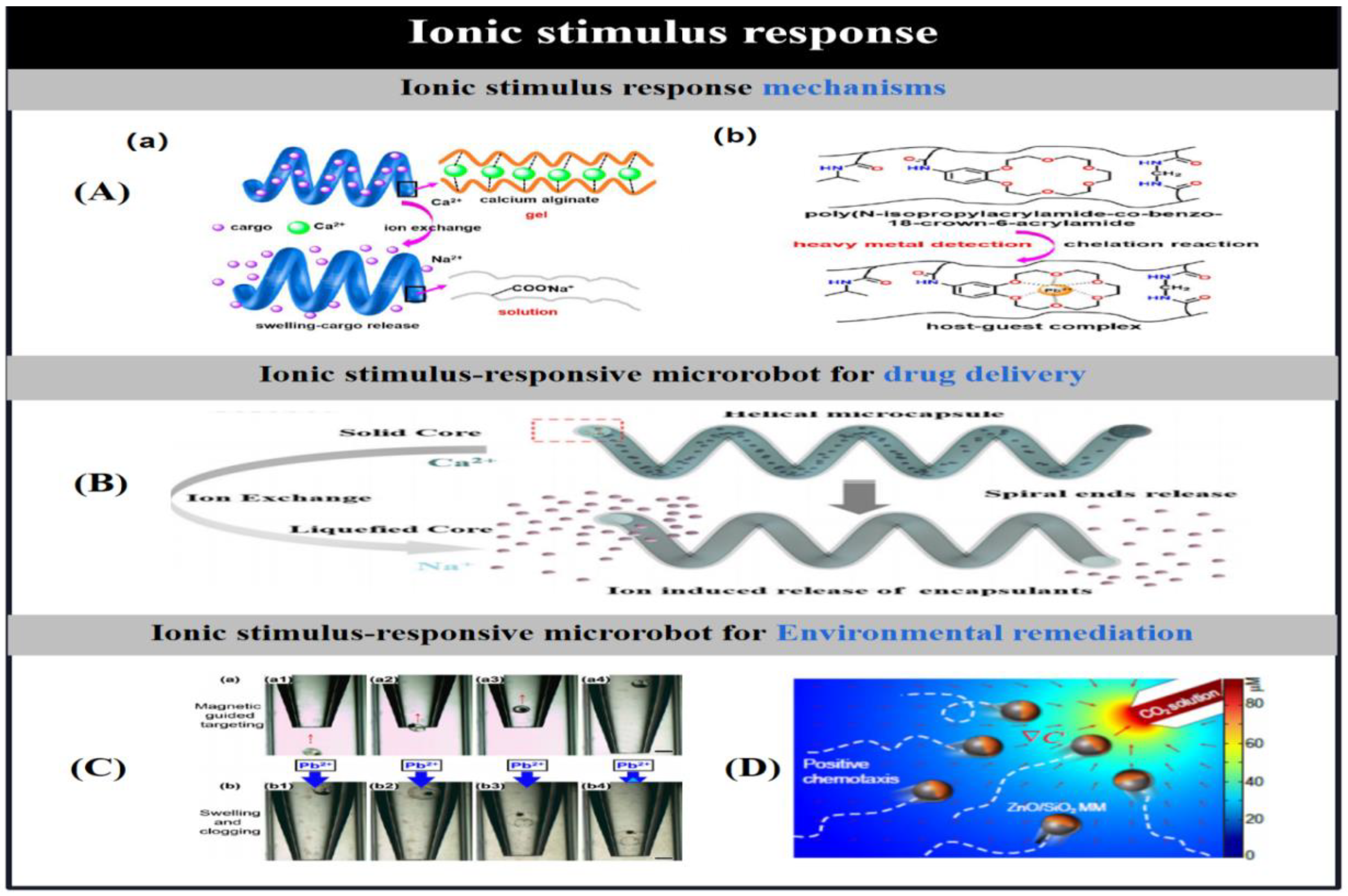
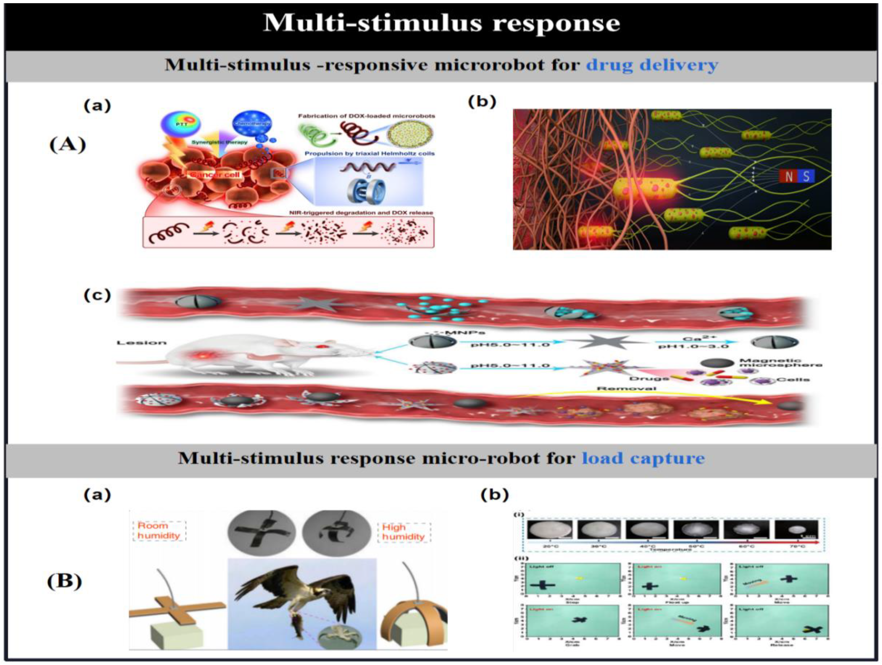
The actuation of microrobots by an applied energy field can enable directional navigation of microrobots in various types of fluids without the aid of chemical fuels. The use of magnetic fields to drive particles holds great promise for many biomedical applications because low-intensity magnetic fields cause little or no damage to biological tissues and the motion of particles in the presence of magnetic fields is tunable [8,11]. Magnetically driven miniature motors are expected to be used in the induction of neuron-like cell differentiation [5,9], cancer therapy [14,20], cell manipulation [15], drug delivery [3,4,30,57] and many other biomedical applications. In addition, magnetic micromotors can also be used in the field of environmental remediation [12,13]. As the size of the micromotors is further reduced or the distance between the particles and the applied magnetic field source is increased, the motion behaviour of helically structured particles in vivo becomes more popular. Therefore, among the many structures of micromotors, magnetically driven micromotors are usually helical structures. Inspired by the artificial bacterial flagellar drive, researchers have developed a large number of helical micromotors that can convert rotational motion around the helical axis into translational rotational motion along the helical axis [9,30]. Ultrasound, as another biocompatible applied energy source, has been widely used in medicine. To date, researchers have developed a large number of ultrasound-driven micromotors [2,3,4,5,6,7]. On this basis, Park et al. [3] used ultrasound to drive a microrobot and demonstrated the effect of different drug release modes on the therapeutic effect of cancer cells. In addition, light and electricity can also be used as external energy sources to drive the particles, laying the foundation for the further development of multifunctional microrobots.
The ultimate goal of the preparation is to create microrobots that can be used in various application scenarios such as biomedicine [2,3,4,5,17,20,21,23,24,27,52,58,59,60,61] and environmental remediation [19,62], among others. Therefore, methods to make particles move should be developed for the characteristics of different types of microrobots and the corresponding application scenarios. So far, by establishing reasonable stimulus-response mechanisms, particles have been able to perform various biomedical tasks, such as targeted drug delivery 63-66], neuron-like cell delivery and cell differentiation [59], biosensing [67], bioimaging [59], and early cancer diagnosis [33,34]. Meanwhile, recent findings have shown the great potential of particles in environmental monitoring and remediation processes [68,69].
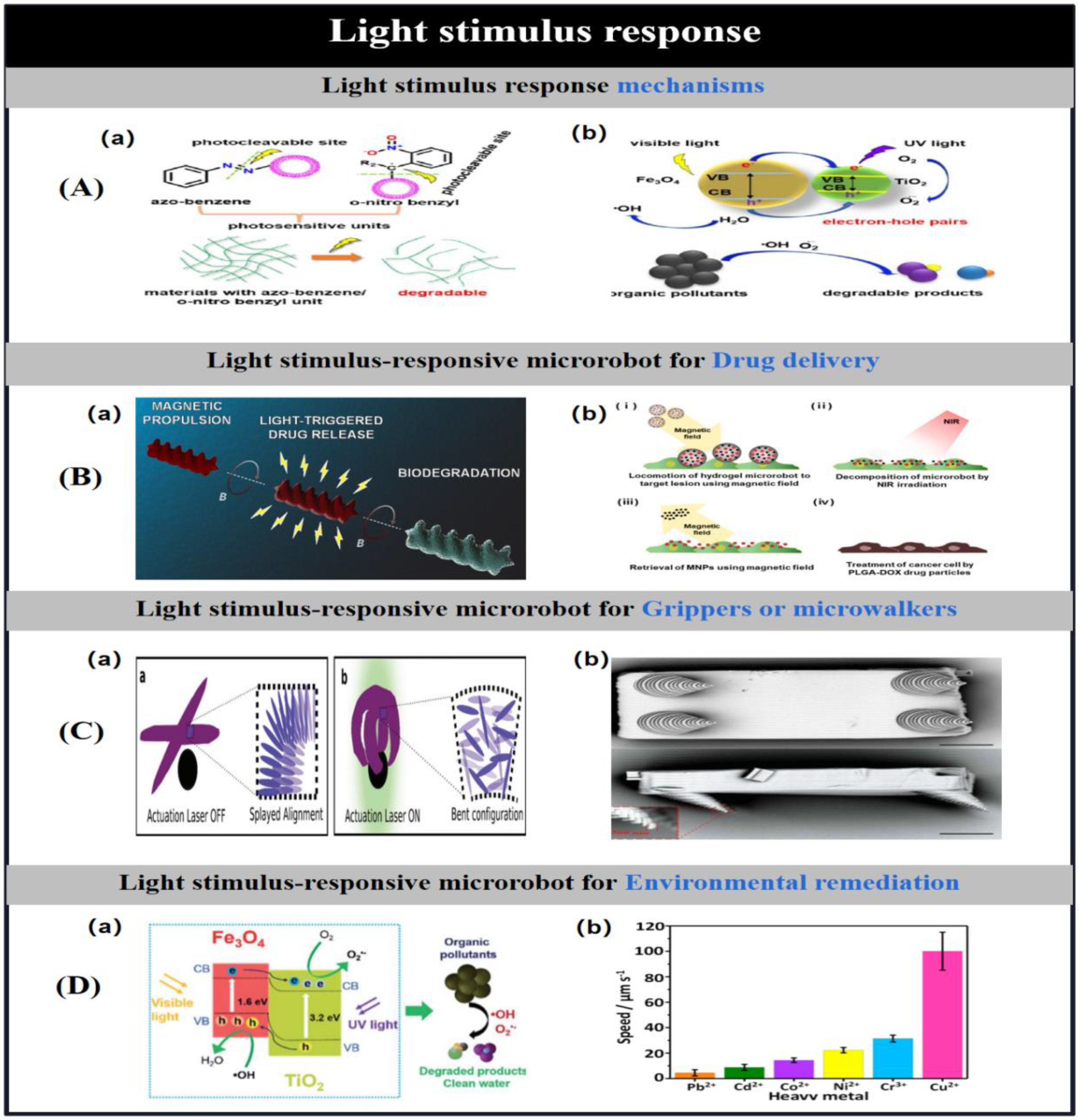
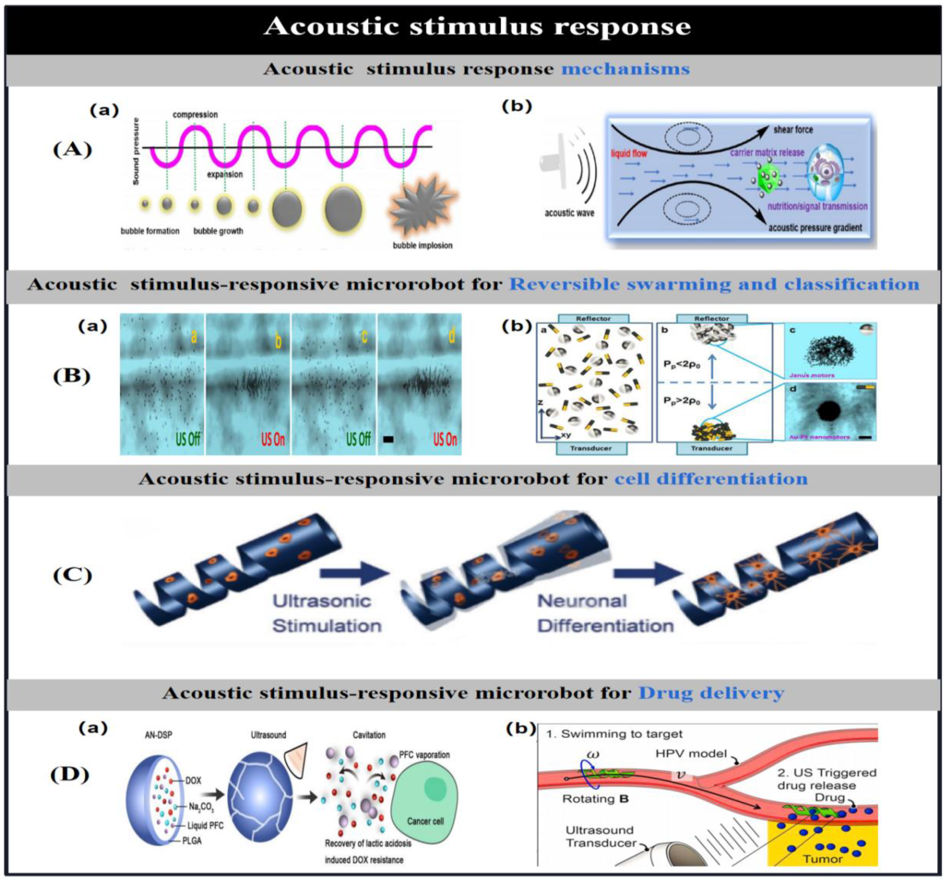
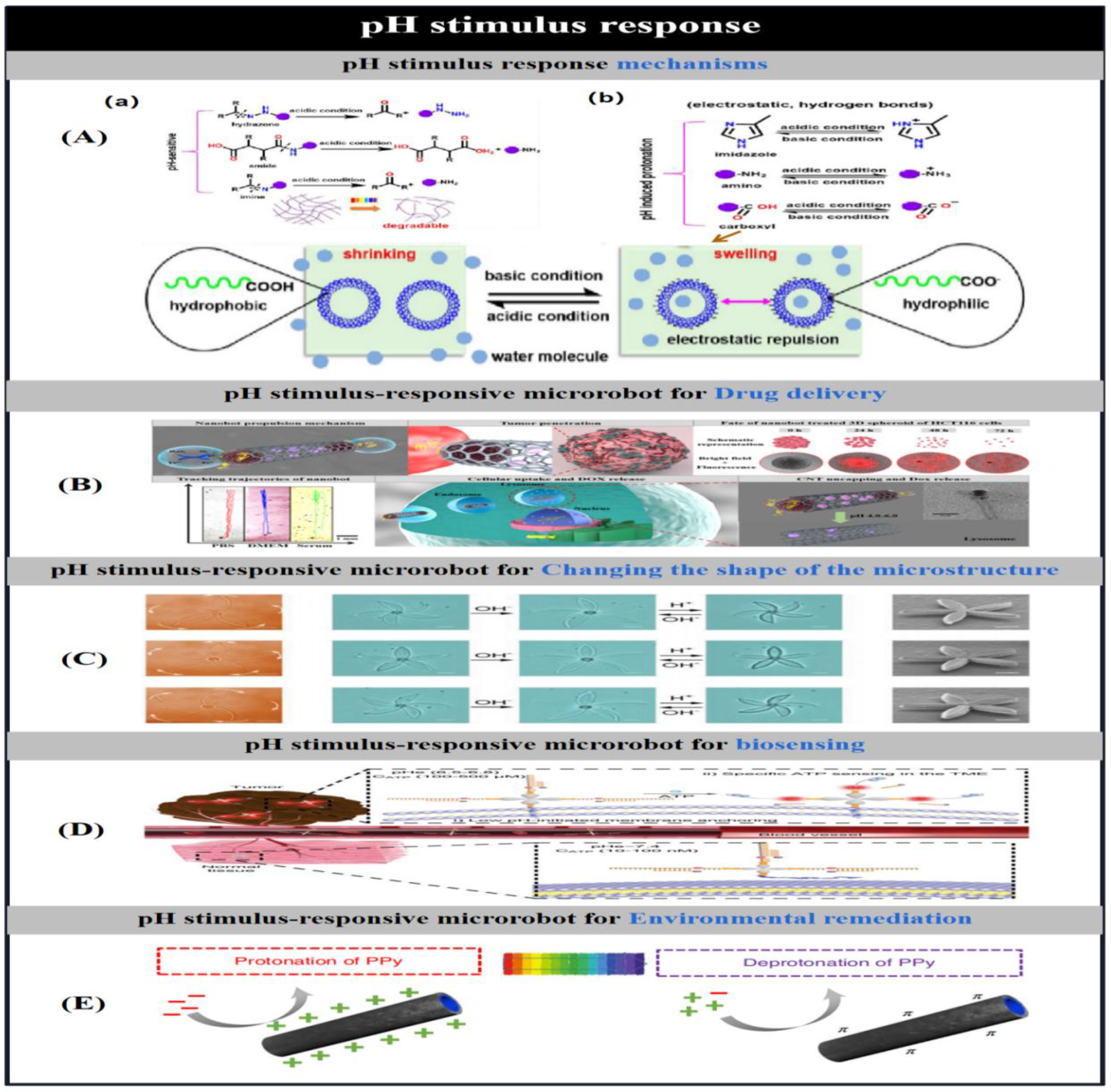
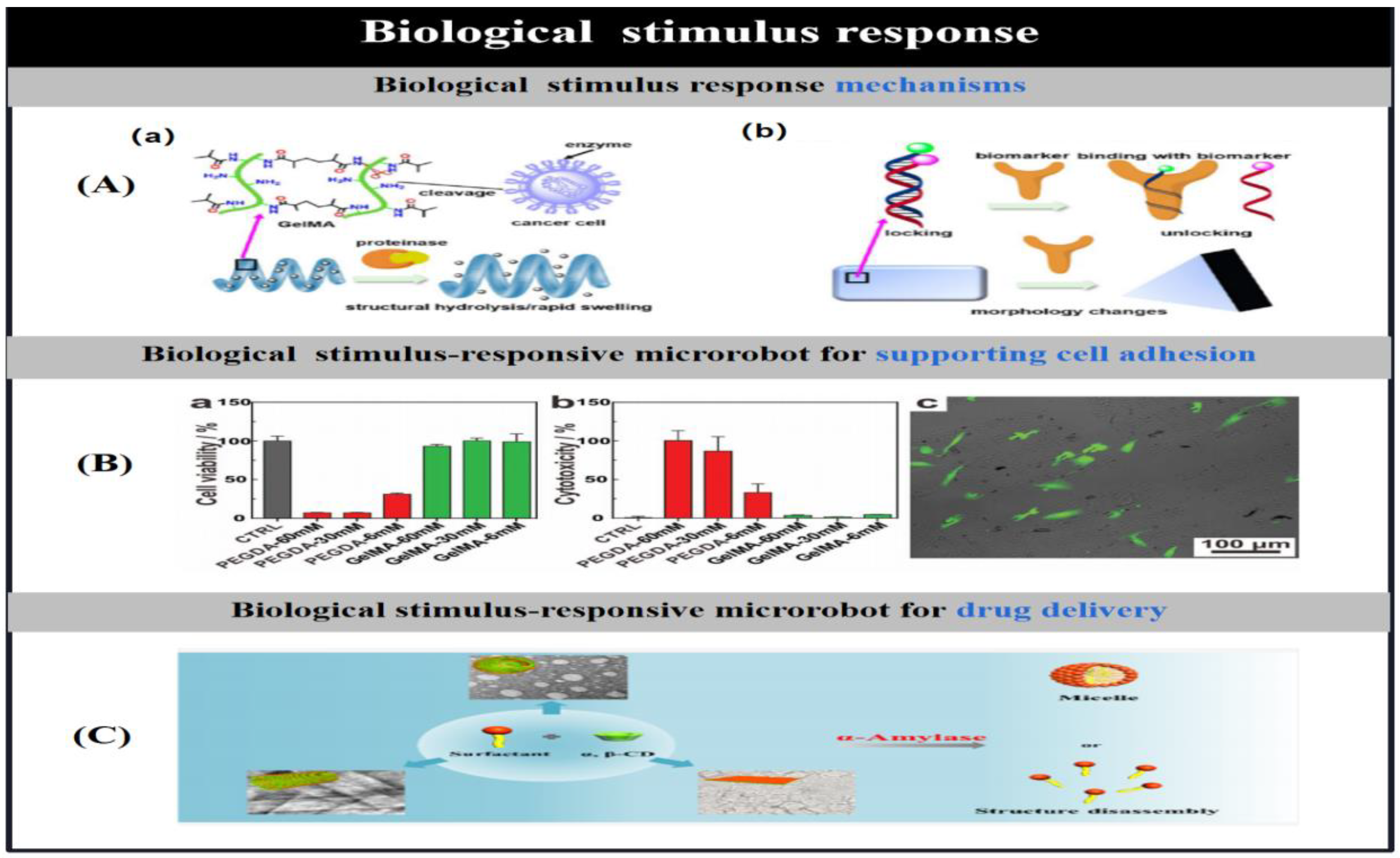
With the further development of nanotechnology, the preparation methods [70] and stimulus response mechanisms [1] of micro/nanorobots and their related applications have been successively reported(Figure 1).This review highlights the different methods of particle preparation and the factors that influence particle design, such as shape, composition and material distribution, followed by a description of stimulus-response mechanisms for microrobots and their applications. Finally, the current challenges facing microrobots are highlighted and possible solutions are proposed to facilitate the practical application of microrobots. By reviewing the research progress of artificial microrobots in recent years in terms of preparation methods, stimulus response mechanisms and applications, we aim to illustrate the current opportunities and challenges facing artificial microrobots, and thus hope to provide inspiration for the development of novel preparation methods as well as actuation approaches.

2. Preparation of Microrobots

As the development of nanotechnology has led to the emergence of different methods to produce versatile micro/nanorobots, the key to the preparation of micromotors is to break their original symmetry by design, so that the particles have an asymmetry that enables them to move under chemical or externally driven conditions to perform complex tasks. This section describes the preparation methods to produce micro- and nanorobots with different structures that can be used in different scenarios through different actuation methods (Table 1).

2.1. Electrochemical Depositions

Electrochemical deposition, also known as electrodeposition, allows the synthesis of various metallic and polymeric materials into microrobots with arbitrary three-dimensional geometries, without the need for expensive tools and harsh experimental conditions, and with the ability to scale up or down depending on the requirements of the microrobot, so that microrobots of different sizes can be produced using electrodeposition techniques. An applied current is usually used to deposit the material, but the deposition process can also be carried out by redox reactions.

2.1.1. Membrane Template-Assisted Electrodeposition

Membrane template-assisted electrodeposition is used to synthesise various materials such as polymers, metals, semiconductors and carbon into desired tubular or nanowire structures using thin film micropores [71,72,73,74,75], which act as a reactor in which the desired micromachines are synthesised per capita. Due to the monodisperse diameter and high microporous density of membrane micropores, they can be used to mass-produce microrobots with similar nanostructures.
Typical membrane materials used are alumina membranes [76] and trace-etchable polycarbonate membranes [77].The length of the prepared microrobots is proportional to the electrical charge and the diameter of the particles is matched to the diameter of the micropores. Depending on the chemical nature of the pore walls and the inherent properties of the material itself, the prepared nanostructures can be solid or hollow.Membrane template-assisted electrodeposition provides an efficient and relatively low-cost method for the preparation of nanowires [78], nanotubes or helical micromotors. This section discusses the use of membrane template-assisted electrodeposition for the preparation of nanowires, nanotubes and helically structured micromotors.

2.1.1.1. Electrodeposited Nanowires

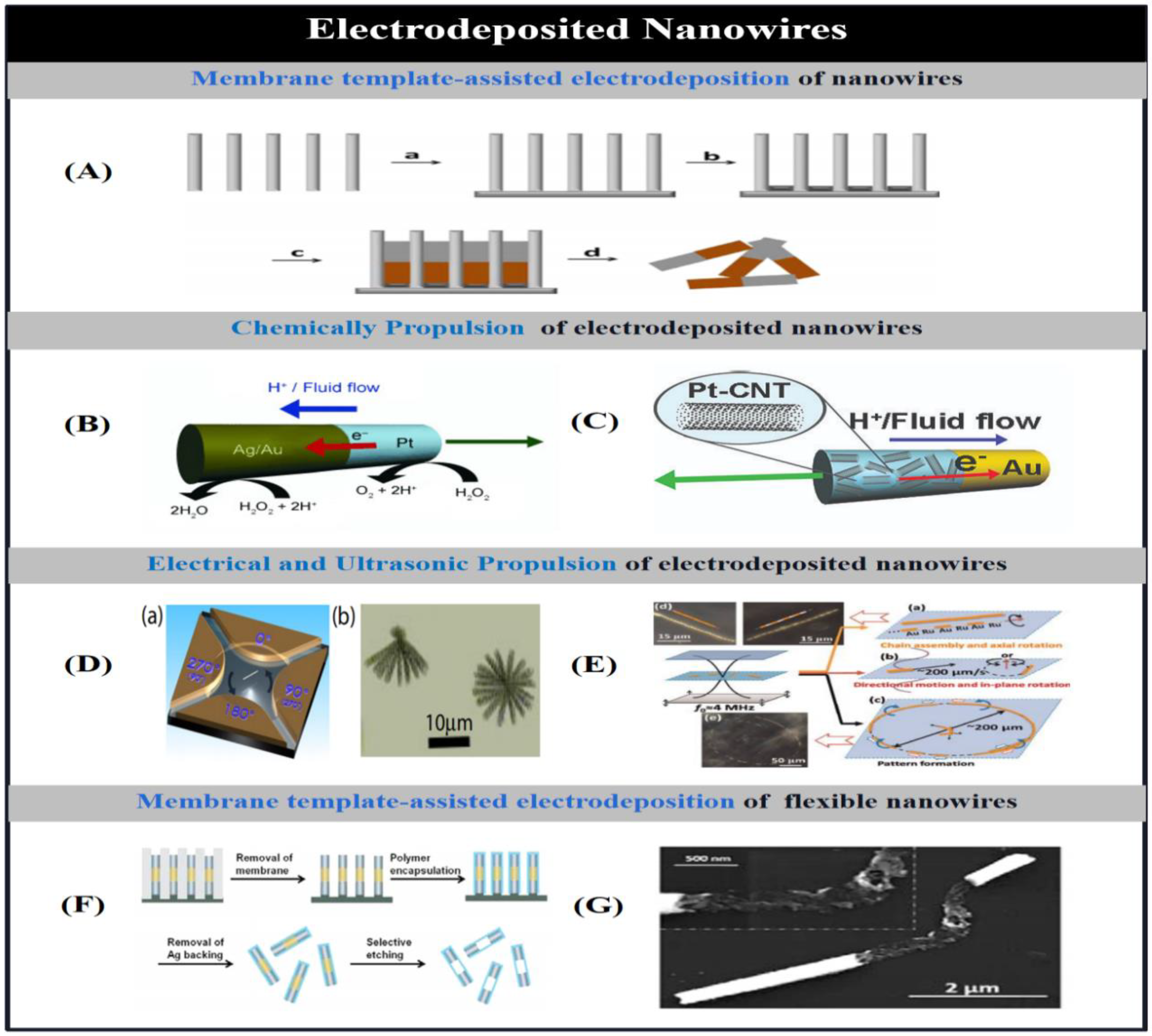
Paxton et al. [71] were the first to prepare bimetallic gold-platinum nanowires with a diameter of 370 nm and a length of 2 um using membrane template-assisted electrodeposition, which move along the axial platinum end direction in 2-3% H2O2 aqueous solution and at a rate of up to 10 times the body length per second. up to 10 times the body length per second. These bimetallic nanowire motors are mainly prepared by the membrane template-assisted electrodeposition method, based on which Fournier-Bidoz et al. [79] proposed a modified electrodeposition method to prepare bimetallic nanowire motors. A silver/gold layer was first deposited on one side of the membrane by physical vapour deposition to act as the working electrode. The membrane was then assembled in a Teflon plating bath and a flat aluminium sheet was placed on top of the metal layer to act as a conductive contact for subsequent electrodeposition. Typically, a copper or silver sacrificial layer is deposited first, followed by the deposition of the various desired metal materials. The silver/gold substrate and sacrificial layer are then removed by physical polishing or chemical etching, and the aluminium oxide membrane is placed in a sodium hydroxide solution to dissolve it.After successive rinsing and centrifugation, the nanowire motors are released from the template and collected. By using an alumina membrane with nano-sized micropores and sequentially depositing different metals into the micropores, threaded rod-like nanowire motors (Figure 2A) were prepared, and the nanorods were driven to achieve uniform circular motion by the oxidative decomposition of hydrogen peroxide into oxygen at the unconnected nickel end of the bimetallic nanorods. These bimetallic nanorods are self-driven by the catalytic decomposition of hydrogen peroxide into water and oxygen, and the driving principle is based on a number of different mechanisms such as interfacial tension gradient, bubble recoil, viscous Brownian ratcheting and selfelectrophoresis to convert the chemical energy into mechanical energy required to move the system. Ambulo et al. [80] used the hydrogen peroxide reaction at the cathode and anode of different metallic ultramicroelectrodes to determine the mechanical energy required to move each metal. Tafel images to determine the potentials at equal rates of cathodic and anodic reactions on each metal, and then predicted all possible directions of motion of the bimetallic assemblies based on the electrochemical mechanisms of the bimetallics, further confirming the bipolar electrochemical driving mechanism of the bimetallic nanorods.
Typically, the preparation process and nanowire structure are improved to produce these bimetallic nanowire motors with higher speed and efficiency.Demirok et al. [81] enabled the fuel-driven nanowire motors to achieve a significant increase in speed to more than 150 μm/s by replacing the cathodic pure gold segments with silver-gold alloy segments (Figure 2B), and further optimised the catalytic activity and efficiency of the nanowire motors by adjusting the alloy composition, including the spatial distribution of metals in the cathode segments, to further optimise the catalytic activity and efficiency of the micromotor. On the same principle, Laocharoensuk et al. [82] achieved a significant increase in the speed of the micromotor in hydrogen peroxide solution by incorporating carbon nanotubes into the platinum component of the asymmetric metal nanowire motor (Figure 2C). Since the running speed of bimetallic nanomotors prepared by hydrogen peroxide fuel electrochemical deposition is related to the surface area of the catalytic segments of the nanorods, Zacharia et al. [83] increased the running speed of the nanomotors by increasing the surface area of the catalytic segments by introducing porosity and increasing the surface roughness of the catalytic segments. In addition to the use of common hydrogen peroxide solutions to drive bimetallic motors prepared by electrodeposition, Liu et al. [40] introduced an efficient bubble-free nanomotor consisting of copper-platinum segmented nanorods acting as nanocells in dilute bromine or iodine solutions. The nanorods are motorised by the self-electrophoretic action resulting from redox reactions generated at different metal segmentations. In aqueous bromine solution, the ionic gradient generated by the asymmetric dissolution of copper causes the asymmetric ratchet-shaped pure copper nanorods to rotate and tumble.
Such membrane template-assisted electrodeposition of nanowires can also be driven by the use of applied acoustic, optical, magnetic and electric fields, in addition to the use of chemical fuels for self-propulsion. For example, Fan et al. [73] caused bimetallic nanowires to rotate at a controlled high speed using rotational forces generated by alternating voltages applied to multiple electrodes (Figure 2D). In addition, Fan et al. [72] actuated nanowires in a suspended state by applying an AC electric field to microelectrodes. These nanowires can be arranged in lines and chains and can accelerate perpendicularly or parallel to their own direction and aggregate at a specific location and diffuse in a controlled manner even at low Reynolds numbers.Suk et al. [84] described that microsemiconductor diodes suspended in water in the presence of an AC electric field generate localised electro-osmotic currents around the diode particles, which drive the particles towards either the cathode or the anode depending on the surface charge.
Wang et al. [85] used standing ultrasonic waves in the MHz range to drive metal nanorods with a diameter of 330 nm and a length of 2 um in water or high ionic concentration solutions, which could be suspended, driven, rotated, aligned and assembled under the action of an acoustic field (Figure 2E). When the ultrasonic frequency is tuned as a vertical wave, these metal microrods are suspended in the cylindrical cell centre plane; when continuous or pulsed acoustic waves are used, the metal microrods undergo rapid axial motion at 200 um/s at the resonant frequency. The rods also self-align and self-assemble into long rotating chains, which in the case of bimetallic rods form an alternating head-to-tail structure, and these chains form rings or stripes in the plane of suspension. This mechanism of directional movement of the metal nanowires under the action of the acoustic field is due to the asymmetry of the nanowires themselves, since during the electroplating process the ends of the nanowires are concave and convex, respectively, and not flattened. When ultrasonic waves are applied, the concave section collects the scattered energy of the sound waves, while the convex end attenuates the energy density, thus generating acoustic pressure at the asymmetric ends and enabling propulsion. While Nadal et al. [86] attributed the propulsion of a microrobot under the action of an acoustic field to the asymmetric steady fluid flow caused by the asymmetric shape. To further enhance the asymmetric distribution of acoustic pressure and the actuation properties of the particles, Garcia-Gradilla et al. [87] used spherical lithography to control the formation of concave cavities. To further enhance the concave cavity, polystyrene nanospheres were implanted into the nanopores of a silver jet film as a second sacrificial layer, and after deposition of various other metals, the nanospheres were dissolved to form a concave cavity at the bottom of the nanowire.
Magnetic nickel nanowires prepared by membrane template-assisted electrodeposition have a near-surface behaviour [88], which can move along an arbitrary surface under the action of an applied rotating magnetic field while transporting loads [78]. However, such magnetically driven rigid nanowires are difficult to apply to some desired scenarios due to limitations in working environment and mobility, so Abbott et al. [89] proposed novel magnetically driven flexible nanowires consisting of a magnetic nickel head and a flexible tail segment, where the nanowire motors are braked when the applied magnetic field is aligned with the magnetic nickel head, and then driven by mechanical deformation of the flexible segment [90].
The preparation of flexible nanowires using membrane template-assisted electrodeposition is similar to that of rigid nanowires, with the additional step of using flexible polyelectrolyte multilayer segments (flexible hinges) to connect rigid nickel and platinum segments [90]. The flexible polymer hinges were achieved by using polyelectrolytes to encapsulate the Ni/Au/Pt nanowires by layer-by-layer electrostatic assembly, followed by selective etching of the metal segments using potassium iodide solution to expose the flexible polymer hinges (Figure 2F). In the presence of an applied fluctuating magnetic field, the nickel segments of the hinges are deformed to achieve radial forward fluctuating motion [91]. On this basis, Gao et al. [74] constructed flexible nanowires with bendable silver segments. Flexible gold-silver-nickel nanowires without fuel magnetic drive were prepared by membrane template-assisted electrodeposition, with partially dissolved and weakened silver bridges connecting the gold head and nickel tail. Under the action of an applied rotating magnetic field, the silver bridge generates cyclic mechanical deformation and also causes the nickel segments to rotate, resulting in the gold segments having different amplitudes, breaking the symmetry of the system to achieve motion (Figure 2G). Motion of magnetically driven nanowires (forward or backward and their state of motion).

2.1.1.2. Electrodeposited Micro/Nanotubes

Segmented nanowires in hydrogen peroxide solution are driven by the bimetallic electrochemical degradation of hydrogen peroxide solution, which generates an self-electrophoretic electrokinetic mechanism to achieve the drive, and the nanowire travel speed and the resistivity of the solution satisfy a linear relationship, and the nanowire travel speed decreases when the ion concentration is increased, which will limit the application of chemically driven nanowires in high ion concentration environments [92]. Therefore, Sanchez et al. [93] proposed a tubular microengine, the inner surface of this microengine degrades hydrogen peroxide to produce bubbles, the bubble recoil mechanism formed drives the microtubes to perform translational [94], helical [95] or circular motions [93,96] at higher speeds, and by adding a magnetic layer to the microtubes, it is possible to multiply the trajectories under the action of the rotating magnetic field for control and positioning [97,98].
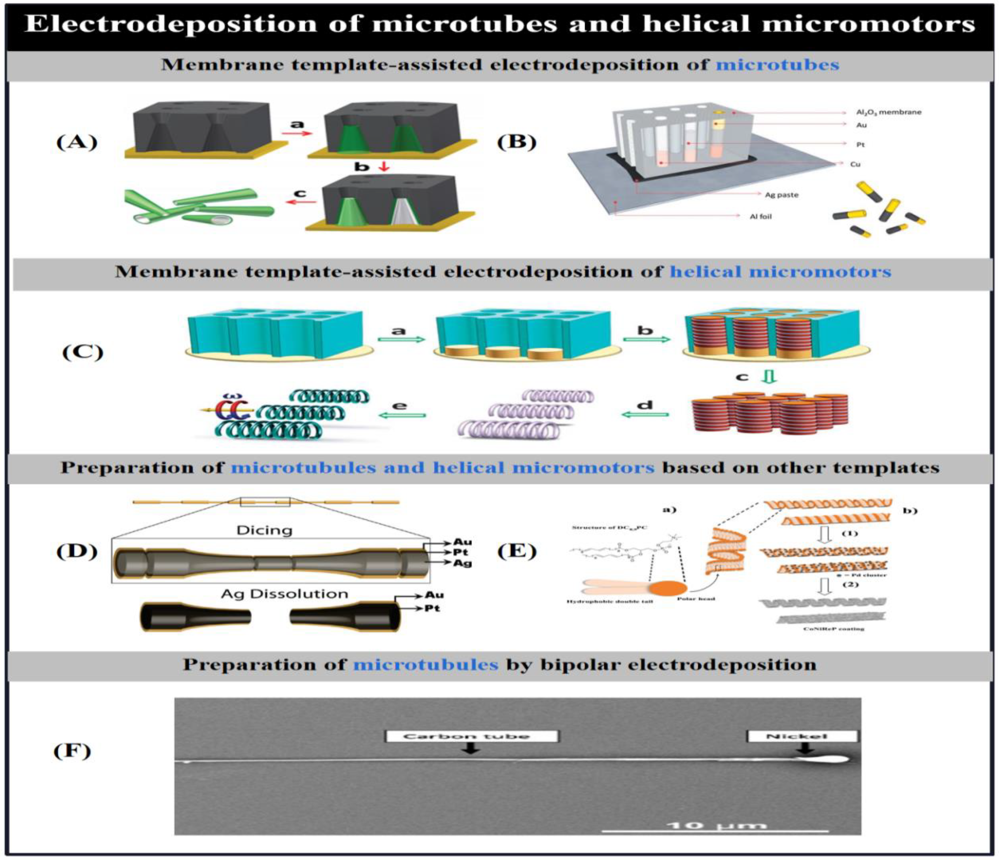
Similar to the preparation of nanowires using membrane template-assisted electrodeposition, Gao et al. [77] used electrochemical growth to prepare bilayer asymmetric polyaniline (PANI)/platinum microtubes using symmetrical biconical microvias on a polycarbonate membrane template (Figure 3A). The plating bath assembly process was identical to that for nanowires, followed by rapid synthesis of highly efficient catalytic microengines due to the presence of aniline monomers, which were first electropolymerised due to the presence of hydrophobicity and electrostatic effects, followed by the deposition of metallic platinum. The resulting microtubule engines are conical in shape, their length and diameter depend on the aperture size of the thin film plate, and they move very fast (350 body length/s) in low concentrations of hydrogen peroxide solution.
To further optimise the composition and electropolymerisation conditions of polymer-based microtubule motors, Wei et al. [99] investigated the effects of material composition and electropolymerisation conditions on the propulsion of polymer-based bilayer microtubule microrobots fabricated from a novel template, comparing the effects of different polymerised outer layers and different metal inner surfaces on the motion of bilayer microtubules, and analysing the effects of electropolymerisation conditions (monomer concentration and medium) on microtubule morphology and kinematic properties. The most efficient drive was found to be that using PEDOT, which achieved record-breaking speeds of over 1400 body lengths/s in a physiological environment, the fastest of any man-made micromotor to date. An internal platinum-nickel alloy layer effectively combines magnetic guidance and catalytic fuel degradation in a single layer, greatly simplifying the fabrication of magnetically guided microrobots. Polymerisation-based microrobots with an internal gold layer can be efficiently biocatalytically powered in a low concentration of hydrogen peroxide solution linked to catalase. microrobots with electrochemically prepared gold-platinum bimetallic layers can be driven at high speeds by the functionalised metal outer surface.
As an alternative to the platinum-catalysed decomposition of hydrogen peroxide as an energy source, Gao et al. [54] described the effective self-propulsion of tubular (polyaniline) PANI-Zn-based micro-rockets in strongly acidic environments without the use of additional chemical fuels. The acid-driven, hydrogen bubble-propelled micro-rockets were fabricated using conical polycarbonate templates that were propelled to achieve self-propulsion in acidic media by hydrogen bubbles generated by simultaneous redox reactions on the internal zinc surfaces. And the velocity-pH dependence of pH measurements under strong acidic conditions was obtained based on the driving characteristics of the micro-rockets in different acidic media and in human plasma. In addition to polymer-based tubular microengines, complete concentric metal microtubes can also be fabricated using the membrane template-assisted electrodeposition method [100]. It simplifies the fabrication process by using graphite colloids instead of deposited metal substrates, thus avoiding the jetting process of physical vapour deposition. In contrast, Zhao et al. [75] fabricated threaded metal nanotubes with a diameter of 300 nm by electrodeposition of silver ink on an anodic alumina membrane template using aluminium foil as the working electrode. In contrast to concentric wound microtubes, this nanomicrotubule has a peculiar segmented structure in which different metals are arranged longitudinally (Figure 3B).

2.1.1.3. Electrodeposited Helical Micromotors.

Liu et al. [101] prepared palladium nanosprings by anodic alumina membrane-assisted electrochemical deposition using nanochannels. The hydroxyl-terminated surface of the nanochannels selectively absorbs hydrogen ions at a suitable pH, resulting in the formation of compact layers. In the presence of an effective potential and an electroplating solution consisting of PdCl2, CuCl2 and HCl, the hydroxyl-terminated surface of the alumina nanochannels and the localised precipitation of hydrogen contribute to the growth of palladium atoms at the outer sites of the alumina nanochannels, where palladium is automatically wound onto copper nanorods by helical dislocation, and palladium nanosprings are obtained after selective removal of copper. Using this approach, Li et al. [102] prepared very small but highly efficient helical magnetic nanowires by template electrosynthesis, which can be efficiently driven under low rotational magnetic fields (Figure 3C). Palladium-copper nanorods were fabricated into nanoporous thin film sheets by template electrodeposition, then the copper was removed and a magnetic nickel layer was deposited on the palladium nanospiral structures by electron beam, and then the palladium nanospiral structures were obtained. When the helical nanomotors were prepared by the template-assisted electrodeposition method, the diameter and length of the micromotors could be adjusted by adjusting the diameter of the nanopores and the ion concentration in the plating solution.

2.1.2. Electrochemical Deposition Based on Other Templates

The template used for electrochemical deposition can not only be a porous membrane, but also the shape of the template can be chosen depending on the structure to be prepared. Manesh et al. [103], on the other hand, used a simplified template-assisted layer to prepare catalytic conical tubular microengines, based on the sequential deposition of Pt and Au on etched silver wires, followed by dicing and dissolution of the template (Figure 3D). This approach allows control of the parameters of the tubular engine, thus improving the performance of the microengine, which is actuated by the formation of a bubble recoil mechanism by internally generated oxygen microbubbles that break the ionic strength limitations of the catalytic nanowires to produce salt-independent motion. However, this method is not suitable for batch preparation and the speed of the nanotubes produced is relatively limited.
Schuerle et al. [104] used self-assembled tubes and the helical structure of diacetylenic phospholipid 1,2-bis1,2-bis(10,12-tricosadionyl)-sn-glycero-3-phosphocholine (DC8,9PC) as templates, which were achieved by transforming the lipid backbone structure into a rigid helix or hollow tube shape that can be magnetically manipulated after coating with a uniform alloy. In this case, the microstructures of tubular liposomes were obtained by diffusion of DC8,9PC in an aqueous solution of ethanol after heating and cooling at the temperature of chain fusion, while helical liposomes were formed in ethanol with water. The resulting liposomes were activated by chemically deposited platinum clusters to maintain shape, and then the resulting rigid structures were subjected to CoNiReP plating solution to coat them with an alloy layer for magnetic manipulation (Figure 3E).

2.1.3. Asymmetric Bipolar Electrodeposition

Janus particles, as a special type of nanoparticles with asymmetric surfaces having significantly different physical or chemical properties and orientations, are generally prepared by asymmetric chemical electrodeposition [105]. Bipolar electrochemistry refers to the fact that when a conductive substance is placed in the middle of a strong electric field between two electrodes, a potential difference is created between the two ends of the substance, and the polarisation intensity of the conductive substance is proportional to the strength of the electric field and to the characteristic dimensions of the substance, which produces asymmetric activity on the surface of the substance in a wireless manner. When the polarisation strength is high enough, an electrochemical reaction occurs at both levels of the substance, breaking the symmetry of the substance and creating two-sided properties.
Bipolar electrodeposition of a variety of materials, including metals, semiconductors, insulators and molecular layers, has been used to produce Janus particles of different sizes and shapes. Bipolar electrodeposition of metals generally involves applying a vertical electric field to the particles, which induces a redox reaction in the particles, resulting in the reduction of metal salts at the cathode and the formation of metal deposits on the surface of the particles. Catalytic and magnetic Janus particles prepared by bipolar electrochemistry can be used as self-powered or magnetically driven micro-engines. For example, Loget et al. [106] used the technique of bipolar electrochemical deposition to prepare asymmetric nanoparticles - carbon microtubes. A suspension containing carbon microtubes was added to a capillary containing a nickel salt solution and then a high intensity electric field was applied to orient and polarise the individual microtubes. The ends of the tubes are the sites of water oxidation and nickel ion reduction, where the water is oxidised and bubbles are generated to form a bubble recoil mechanism, and when the polarisation intensity of the microtubules is sufficiently high, they are driven through the capillaries by the bubbles, and the nickel deposited at one end of the microtubule causes it to achieve directional motion under the manipulation of the magnetic field (Figure 3F). This method of bimetallic electrochemical deposition using a cell avoids the immobilisation of particles on the surface and the deposition structure can be tuned by changing the direction and amplitude of the electric field and the viscosity of the medium.

2.2. Physical Vapor Deposition

Physical Vapour Deposition is used to deposit thin layers of material as a vapour coating. The solid material is vaporised using a high temperature vacuum or gaseous plasma and the vapour is then transported to the surface of the vacuum substrate where it condenses to form a thin film. Physical vapour deposition is typically of two types: sputtering, where a solid target material is bombarded with a plasma gas to vaporise it, and electron beam evaporation, where an electron beam is used to vaporise atoms from a target state to a gaseous state, and the gaseous material produced by both techniques is then deposited onto a metal surface. This section describes conventional physical vapour deposition and modified swept angle deposition.

2.2.1. Conventional Physical Vapor Deposition

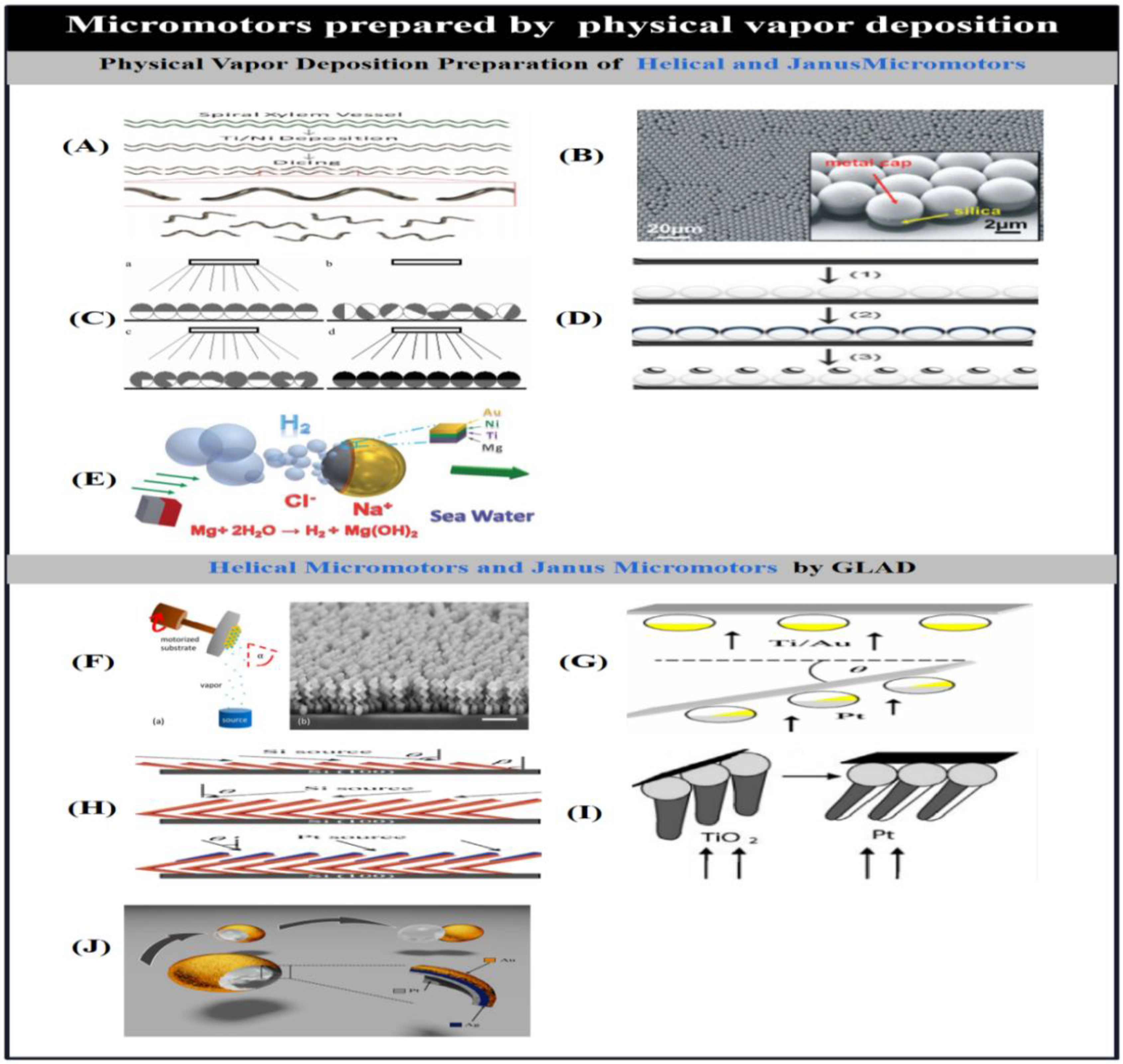
Physical vapour deposition directly transforms the target material into microstructures with the desired properties. In the manufacture of microrobots, it is possible to introduce inert materials that catalyse or block reactions, and magnetic materials that allow directional movement in the presence of a magnetic field. Magnetically actuated micromotors are fabricated by first preparing a template suitable for magnetic actuation and then depositing the magnetic material using physical vapour deposition. Templates for magnetic actuation can be prepared by various methods such as swept-angle deposition, 3D laser direct writing or by directly using naturally occurring structures.Gao et al. [107] introduced a magnetically actuated helical micro-swimmer. The geometric variables of the spiral vessel (spiral diameter and pitch) can be controlled by mechanical stretching to achieve precise preparation and consistent performance of the spiral microswimmer. Thin layers of titanium and nickel were deposited directly onto the spiral vessels by electron beam evaporation for dicing to achieve mass production of versatile micro-spiral swimmers (Figure 4A). In addition to using magnetic forces and moments to drive the magnets, Baraban et al. [108] used magnetic field-induced thermophoresis to enable the movement of silicon spheres with magnetic caps. Magnetic spherical Janus micromotors fabricated by physical vapour deposition were used to induce thermophoretic motion of particles by heating their magnetic caps using an AC magnetic field, while a DC magnetic field was used to orient and guide the Janus micromotors for long time scales of motion. The Janus micromotors are highly bio-adaptable because they no longer use chemical fuels, and the topologically stable magnetic vortex state of the Janus micromotor cap structure is achieved by the special properties of the ultra-thin, 100 nm thick polymerised magnetic film, which allows full control of the motions.
In order to enable nanowires fabricated by template-assisted electrodeposition to achieve unrestricted rotational motion rather than purely linear motion, Qin et al. [109] fabricated a gold-platinum-gold tri-segmented nanorotor (diameter of 360 nm; length of the first segment of gold, 1.67 um, and the length of platinum, 1.67 um) by template-assisted electrodeposition-based inline lithography, followed by the deposition of a gold-chromium bilayer coating on the end segment of gold. 3.33um, and a passivation cross section length of 20nm for the gold end segment), the asymmetry of the nanorotor was broken by depositing a gold-chromium bilayer coating on the gold end segment using thermal deposition, which enabled the nanorotor to be propelled by generating a bubble recoil mechanism through the dynamic decomposition of H2O2 in a H2O2 solution. On this basis, Wang et al. [110], after preparing double-jointed Au-Ru nanorods using an anodic alumina film, when the bimetal was released from the alumina membrane, chromium, silica, gold and platinum were sequentially deposited, chromium, silica, chromium, gold and platinum were sequentially deposited on individual sides of the rods by physical vapour deposition to break their original symmetry one by one, so that hydrogen peroxide decomposition can be achieved by the decomposition of hydrogen peroxide to drive, and the additional gold and chromium layers provide vertical forces that move the rod towards the centre of the orbit caused by the asymmetric flow.
In addition to using bipolar electrochemical deposition to create asymmetry, if the orientation of the substrate does not change, the material introduced by physical vapour deposition is then deposited only at one end of the material, allowing the fabrication of Janus micromotors with asymmetric structures. The key to making Janus micromotors using physical vapour deposition is the asymmetric distribution of the catalyst or reactant, which should be placed in an environment containing a suitable substrate (H2O2), where the non-uniform consumption of the substrate and the inhomogeneous distribution of the reactant allows the substance to be driven by the degradation of the hydrogen peroxide, creating a chemical concentration gradient that allows the fluid to flow around the particles and thus drive them [111]. In the fabrication of Janus micromotors, each side of the particles should be selectively synthesised to give different properties, and in the fabrication of Janus micromotors using physical vapour deposition, the symmetry is usually broken with a temporary shield of a hemisphere.
In the preparation of catalytic Janus micromotors, asymmetry is usually introduced by depositing catalytic materials on the hemispherical surface of the particles using physical vapour deposition. For example, Baraban et al. [46] formed self-assembled monolayers of particles by bottom-up deposition of particle suspension droplets in a matrix followed by slow evaporation (Figure 4B). In order to slow down the evaporation process, smaller inclined boxes are typically used for the evaporation process to ensure that an ordered array of particle monolayers is obtained [112]. The area of the resulting monolayer can be controlled by varying the particle concentration and droplet size of the suspension, and the catalytic material is deposited on top of the monolayer, forming a half-shell on the surface of the particles, which is then separated from the substrate by ultrasonic action.
The most common catalytic nanomotors are platinum-catalysed Janus particles, which use the non-uniform consumption of catalysts and the inhomogeneous distribution of reactants to drive the substance by degrading hydrogen peroxide, creating a chemical concentration gradient that allows fluid flow around the particle, thus driving the particle [111].Wei et al. [53] proposed another spherical diffusive motion of Janus particles. The iridium-based catalytic Janus micromotor was prepared by physical vapour deposition of iridium on hemispheres of silica particles. The Janus micromotor relies on the iridium hemisphere layer to catalytically decompose the hydrazine attached to the silica spheres, and the resulting permeation effect allows the micromotor to achieve self-driving at very high speeds in hydrazine fuels of very low concentration, which is a much higher percentage of chemical fuel required to drive the micromotor than to drive a normal catalytic micromotor. Hong et al. [113] demonstrated that the macroscopic order we observe arises from the disordered behaviour of microscopic matter by using UV irradiation of silver-coated colloidal spheres to promote particle motion through the asymmetric release of Ag+ and OOH. In contrast, Wheat et al. [114] used physical vapour deposition to fabricate bimetallic spherical micromotors by spraying one metal onto the surface of the microspheres followed by another metal onto the half surface of the coated metal. This spherical bimetallic motor was self-powered by the electrocatalytic decomposition of hydrogen peroxide through a reaction-induced charge self-electrophoresis mechanism and moved at the same speed as a rod motor with the same dimensions and composition (Figure 4C).
Based on spherical templates, physical vapour deposition can also be used to fabricate micromotors of various structures.Valadares et al. [115] fabricated self-powered spherical dimers using physical vapour deposition. Firstly, a sub-monolayer of silicon microspheres, a thin adhesive chromium layer and a thicker adhesive platinum layer were sequentially deposited in a silicon/platinum matrix, and the metal half-shells were dehumidified by an annealing process, thus attaching the non-catalytic silicon spheres to the catalytic platinum spheres (Figure 4D). In addition, in order to move the micromotor without the use of an applied field, it is necessary to add asymmetry to the particles in terms of their chemical composition or physical geometry, as shown by Zhao et al. [116] using coconut micromotors made of platinum partially or fully etched silica templates. Although the inner and outer surfaces of the micromotor are made of the same material, structural motion can be achieved because bubbles can also be generated on the convex surface, demonstrating that micromotors can be driven not only by chemical but also by geometrical asymmetries, and that partially etched motors are faster than fully etched or Janus micromotors. Tierno et al. [117] applied platinum particles to the micromotor using a vacuum sputtering method to coat platinum particles on the half surface of the particles, producing extended ellipsoidal microspheres with catalytic properties that are self-powered by catalytic decomposition of H2O2.
The alternative drive mechanism for the Janus micromotor is non-catalytic, as the materials that make up the motor are consumed in the drive process. These non-catalytic micromotors are tens of microns in size and are powered by physical gasification, which deposits an inert layer on their surface to create asymmetric bubbles. In order to make non-catalytic micromotors operable with nearby fuels, micromotors are generally fabricated using materials that can react with water. For example, Gao et al. [50] used physical vapour deposition to fabricate micro-Janus micromotors that are no longer powered by ordinary hydrogen peroxide, but are self-powered by a bubble recoil mechanism generated by water actuation. The micromotor consists of microspheres partially coated with an aluminium-gallium dual alloy consisting of a mixture of aluminium particles and liquid gallium microcontacts, where bubbles are generated from one end of the exposed aluminium-gallium alloy hemisphere which collide with the water to provide the forward propulsion. Meanwhile, Gao et al. [55] presented micromotors that achieve propulsion by capturing energy from the reaction of three different chemical fuels (acid, alkali and H2O2). This aluminium-palladium Janus micromotor is achieved by depositing palladium on the side of aluminium particles, and the Janus micromotor is propelled by hydrogen bubbles generated by different chemical reactions of aluminium in strong acid and alkali environments, and oxygen bubbles generated by the palladium coating in hydrogen peroxide medium, achieving high speed and long duration propulsion in acid and alkali media.
Another material used to produce non-catalytic micromotors that can react with water is magnesium.Gao et al. [56] described magnesium-based micromotors powered by chloride-containing seawater (Figure 4E). A nickel-gold bilayer patch was applied to magnesium particles using electron beam evaporation, forming an inert metal cap that could generate asymmetric thrust and facilitate the reaction of magnesium with water using high current corrosion and chloride ion pitting processes, thus enabling the micromotor to be self-powered. Similarly, Fangzhi et al. [118] presented a novel bio-phase-adapted magnesium-platinum micromotor powered by the magnesium-water reaction using sodium bicarbonate. In this case, sodium bicarbonate forms magnesium carbonate in molten water by reacting with magnesium hydroxide, a passivated layer on the surface of magnesium, which facilitates the generation of asymmetric bubbles from the magnesium-water reaction and thus propels the microbot.

2.2.2. Glancing Angle Deposition

In conventional physical vapour deposition, the substrate is typically placed parallel to the target and the gas stream is then deposited from the target perpendicular to the substrate. In contrast, grazing angle deposition (GLAD, also known as dynamic shadowing growth) deposits the gas stream onto the substrate in a grazing incidence beam, with the substrate typically placed at an inclined angle (relative to the gas stream volume) to achieve geometric shadowing. By rotating the substrate in the polar and azimuthal directions, different desired nanostructures can be produced, such as nanorod arrays with different shapes, nanospring arrays or even multilayers [119]. microrobots with complex 3D structures can be fabricated in bulk using swept-angle deposition, and this section focuses on the fabrication of spiral micromotors and Janus micromotors using swept-angle deposition.

2.2.2.1. Helical Micro/Nanomotors by GLAD

Helical growth can be achieved by rotating the azimuthal angle of the tilted substrate during deposition.To prepare helical structures with good homogeneous properties on a large scale and in bulk, it is necessary to crystallise the substrate prior to performing the GLAD process, as the size, shape and homogeneity of the crystalline seeds have a great influence on the properties of the resulting helical structures. An ordered array of crystalline seeds is generally prepared on the surface of the substrate, and Ghosh et al. [120] described the construction and manipulation of helical chiral colloidal actuators prepared by grazing angle deposition. The helical structure is formed by depositing a stream of silica at a given angle of inclination onto silica microbeads in a rotating matrix, followed by deposition of cobalt on the outer surface of the helical structure by thermal evaporation.This allows micrometre precision navigation in water under the stimulation of a homogeneous magnetic field. The size of the helical structure depends on the size of the crystalline seed, and to reduce the size of the helical structure, gold nanodots prepared by micellar nanolithography are usually used as seeds [121]. Regular arrays of gold nanodots were obtained when self-assembled polystyrene-b-poly [2-vinylpyridine (HAuCl4)] bis-block copolymer micelles were spin-coated on wafers to form a homogeneous mono-micellar film, followed by plasma treatment to remove the polymer while reducing the gold salt content. The spacing and size of the nanodots were controlled by varying the molecular weight and spin-coating rate of the diblock copolymer and the gold loading. The helically structured nanodriver has filaments with a diameter of 70 nm, which is smaller than the size of previous nanodrivers and mobile microorganisms, so that Brownian forces hinder its movement in pure water, but it can still pass through highly viscous solutions at speeds comparable to those of a large microswimmer.
Ghosh et al. [122] investigated the minimum size limits of magnetically driven helical motors through experimental observations and numerical modelling and found that at low length scales, directional noise can have a significant effect on the direction and magnitude of the motion of the helical actuator; at length scales less than a few microns for an aqueous medium, the frequency of operation of the drive system must be the inverse of its size due to the limitations of the helical actuator to achieve a cubic value of directional motion. Motion in fluids at the nanoscale is mainly controlled by viscous drag, and an effective means of propulsion is to drive helical microrobots using a weak rotating magnetic field for fuel-free actuation in complex media.Walker et al. [123] demonstrated the optimal length of the actuator by combining analytical and numerical theory with experiments on a nanostructured ferromagnetic helical actuator (a very short, single helical loop).
The grazing angle deposition technique not only enables the growth of complex three-dimensional structures containing different metals such as metals, insulators, semiconductors and magnetic materials, but even the production of binary alloys by simultaneous deposition in two evaporators, where the alloy compositions can be adjusted by individually controlling the deposition rate of the evaporators. During the growth process, ferromagnetic nickel segments can be added to the helical structure instead of coating the helical structure released from the circular wafer with a thin magnetic layer, allowing reproducible production of magnetically driven helical motors with good uniform magnetism. The chirality and pitch of the helical structure can be controlled by changing the direction and speed of rotation of the substrate during the deposition process. However, the physical properties of chiral molecules are weakened due to the destruction of asymmetry, and to study the physical properties of chiral molecules, complex non-spherical colloidal particles can generally be used as colloidal molecules in a macroscopic model system to visualise those molecular phenomena that are difficult to observe, but due to the surface minimisation that favours the growth of symmetric particles, it is difficult to synthesise chiral colloidal molecules. Schamel et al. [124] used physical grazing angle deposition to mass produce chiral molecules and investigated the propeller effect by coupling the dipole moments of the spinning enantiomers through an applied rotational field to separate the exocyclic mixtures and drive them helically in the opposite direction (Figure 4F).

2.2.2.2. Janus Micro/Nanomotors by GLAD

Based on the self-growth effect and substrate rotation during incident vapour deposition, GLAD allows the fabrication of Janus micromotors with complex structures in a simple manner.Gibbs et al. [125] used a dynamic shadow growth method to fabricate asymmetric Pt-Au catalysed micromotors. To obtain an asymmetric bimetallic coating, a substrate with silicon microspheres was rotated to a polar angle after deposition of bonded titanium and gold, followed by deposition of platinum to expose the gold (Figure 4G). The micromotor was driven by an self-electrophoretic mechanism generated by the degradation of hydrogen peroxide fuel in solution, and its average velocity of motion u was u∝A3/2 with respect to the exposed gold surface area A. This catalytic micromotor was more active than a non-self-electrophoretic mechanism-driven micromotor of the same dimensions and morphology, and its movement could be tuned by varying the overlap of the two platinum-gold metals. metals by adjusting the overlap of the two metals to tune their motor behaviour. Lee et al. [38] fabricated Pt-Au Janus micromotors with a size comparable to that of some enzymes (30 nm) by sweeping deposition of gold into arrays of Pt nanoparticles prepared by micellar lithography of block copolymers under rapid rotation of the substrate. This micromotor is also self-powered by catalytic decomposition of H2O2 into water and oxygen and by self-electrophoresis.
A range of Janus micromotors with different shapes can be prepared using the grazing angle deposition technique.Yuping et al. [126] prepared catalytic nanomotors with different geometries and controllable motions, such as rotating silicon-platinum nanorods, rotating L-shaped silicon-platinum or silicon-silver nanorods, and rotating silicon-silver nanosprings, using the dynamic shadow growth method based on the shadow effect and substrate rotation. A silicon nanorod skeleton is first prepared using GLAD, and then platinum or silver is asymmetrically deposited on one end of the nanorod skeleton by geometric shading effect. L-shaped nanorods were obtained by subjecting the substrate to rapid azimuthal rotation at the centre of the tilt angle deposition (Figure 4H), and complex rotatable silicon-silver springs were prepared by further controlling the deposition angle and substrate rotation speed.Gibbs et al. [127] grew platinum-coated titanium dioxide nano-arms by dynamic shadowing growth on micron-sized silica microbeads to prepare a multi-part rotating nanomotor. The arms of the micromotor were deposited at an inclined angle on closely packed microbeads and then platinum was deposited at an angle on only one side of the arm to create asymmetry (Figure 4I), so that the structure rotated around an axis passing through the centre of the microbeads and around an axis perpendicular to the nano-arms when exposed to a hydrogen peroxide solution. By tilting the direction of air flow and rotating the substrate, the resulting deposited layer can cover most of the area of the spherical template compared to conventional physical vapour deposition.Huang et al. [128] fabricated a Pt-Ag-Au shell micromotor by combining physical vapour deposition and wet chemical etching (Figure 4J). The catalytic coating inside the shell decomposes hydrogen peroxide to produce bubbles, but due to the low nuclear energy of the bubbles themselves, they do not block the openings on the shell, and the micromotor achieves actuation under the bubble ejection or bursting mechanism.

2.3. Rolled-Up Technology

Convolution transforms nanofilms into three-dimensional structures such as wrinkles, tubes and spirals through stress design. It does this by applying a stress gradient to the deposited film so that the film forms the desired nanostructure when it is released from the substrate. Currently, the convolution process is mainly used to produce tubular and helical micromotors.

2.3.1. Preparation of Nanotubes Using Rolled-Up Technology

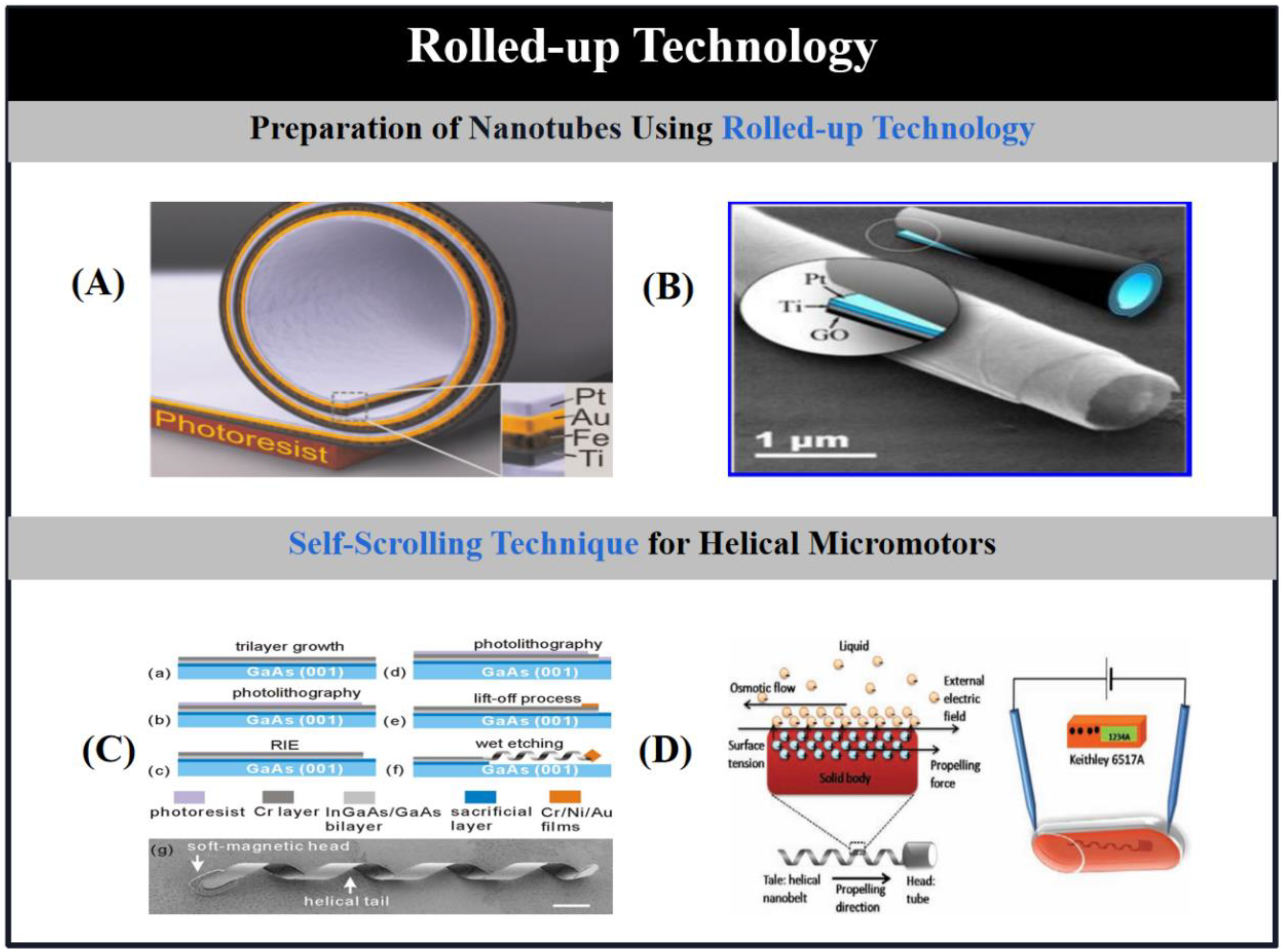
Solovev [97] and Yongfeng et al. [129] were the first to use the convolution process to produce nanotubes. The microtubes consisted of an inner platinum layer (catalytic layer) and an outer iron layer (magnetic remote control), and titanium and copper layers to connect the inner and outer layers and facilitate controlled rolling. Prestressed nanofilms were deposited onto a photoresist sacrificial layer using photolithography, followed by selective etching of the sacrificial layer using acetone. For precise positioning and integration of the tubes on a single wafer, tilted physical vapour deposition was used to create the stress gradient required for the roll-up process by carefully controlling the substrate temperature and rotation rate, as well as the stress variations during the deposition process. Subsequently, the pre-stressed polymetallic film deposited on the sacrificial photoresist layer is released from the substrate surface by etching off the photoresist and the film is automatically rolled up into a tube-like structure (Figure 5A) [97]. To avoid shape collapse of the convolved nanofilms, the microtubes must therefore be dried using a critical point drying technique. The outer layer of these microtubules has a diameter range of 1-30 um, which can be tuned by varying the thickness of the nanofilm and the built-in stresses [130]. In general, the length of the microtubules produced by convolution is in the range of tens of microns. In the preparation process, a catalyst such as platinum is simply deposited on the top of the nanomembrane, which is then folded to form the inner wall of the microtubule. During the release process, the folding orientation of the release film is determined by the crystal structure of the sacrificial layer and by different etching rates along the crystal axis.
To simplify the complex convolution process, Kun et al. [131] fabricated microtubes with an outer layer of graphene oxide by depositing a bimetallic layer on a single graphene oxide nanosheet (Figure 5B). Layered heterostructures containing graphene oxide nanosheets and 20-35 nm bimetallic layers can be easily separated from the silicon matrix by acoustic degradation, and the separated layered heterostructures spontaneously assemble into micrometre-sized coils by combining the material stresses and the weak binding effect between the graphene oxide layers. The diameter of the coils is tuned by varying the thickness of the metal film, and the stresses and structures are controlled as a function of the coiling process by choosing the appropriate materials. Using the same design principle, Hong et al. [132] obtained tissue cells from fruit extracts of banana and fruit, which were used as a substrate on which a thin layer of platinum was deposited by physical vapour deposition. Spontaneously formed microcoils of highly uniform size were obtained by sonic disintegration of the mixed cell-platinum coated matrix in water. The tubular micromotor prepared by the fruit cell film assisted deposition method has the ability to move at high speeds in hydrogen peroxide solution by forming a bubble recoil mechanism.
To further improve the kinematic properties of the microtubes, Magdanz et al. [133] designed flexible thermo-responsive micro-nozzles based on a polymer with a reversible folding/unfolding function that rises and falls with temperature. It is formed by folding a polymer layer containing a thin film of platinum and is self-activated in a hydrogen peroxide solution using platinum as a catalyst. This micro-nozzle allows reversible self-folding in a precise manner by changing the temperature of the solution in which it is placed, and allows multiple rapid starts and stops of the micro-nozzle depending on the adjustment of its radius.

2.3.2. Self-Scrolling Technique for Helical Micromotors.

Bell et al. [134] were the first to fabricate helical nanomotors using the self-rolling technique. Relying on the tension of a thin layer of material, the rolling technique can be used to transform a straight ribbon structure into a helical structure suitable for magnetic actuation. For example, Zhang et al. [135] fabricated helical nanomotors using the conventional method of thin film deposition (Figure 5C). The deposited metal layer was first converted into straight ribbons by reactive ion etching, followed by chemical vapour deposition to prepare magnetic heads for magnetic actuation, and due to the presence of internal pressure in the material, the helical structure would be formed by self-rolling action when the straight ribbons were released from the substrate. Typically, the parameters of the helical substance can be adjusted by varying the deposition conditions such as the film thickness, the width of the straight ribbons and the relative orientation of the straight ribbons with respect to the crystalline structure of the metal. To further investigate the kinematic properties, Li et al. [136] studied the effect of the magnetic head size of the prepared helical structure on its travelling speed. At lower frequencies, the helical material with a smaller magnetic head moves faster than the helical material with a larger magnetic head due to less viscous drag in the fluid. However, because the larger head contains more nickel magnetic material, it is subjected to a stronger magnetic moment, causing its maximum speed to increase.
In addition to the use of rotating magnetic fields, it is also possible to use electro-osmotic forces generated by electric fields to drive helical materials prepared by thin film deposition [137]. The principle of electro-osmotic actuation is realised by exploiting the interface between the surface of the helical structure and the fluid solution (Figure 5D), where in the presence of an applied field the stern layer of the helical structure flows, creating a hydrodynamic pressure on the surface of the helical substance that drives it in the opposite direction. This electro-osmotic actuation of the helix gives it a higher speed of movement and manoeuvrability compared to a rotating magnetic field.

2.4. Three-Dimensional Laser Writing

2.4.1. 3D Printing

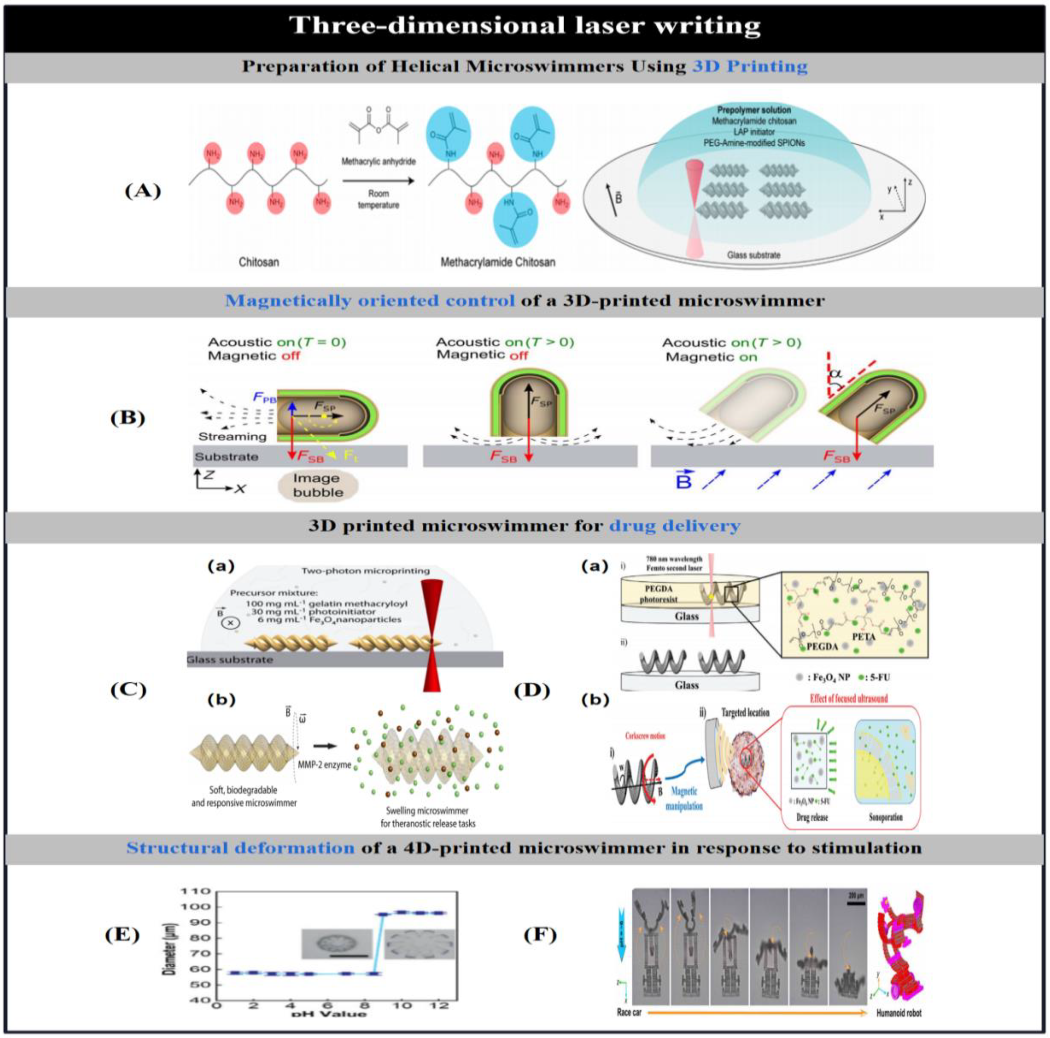
Three-dimensional laser direct writing (DLW) technology allows the precise batch preparation of complex polymer structures at the micro- and nanoscale with high resolution. Typically, we use DLW technology to prepare helically structured micromotors (Figure 6A) [9,20,31,65]. For example, Tottori et al. [138] were the first to fabricate magnetic helical nanomotors by depositing negative photoresist on a substrate and using DLW. When a laser beam is focused on the photoresist, two-photon polymerisation occurs at the focal point of the laser beam, and the unused photoresist is subsequently removed, resulting in a helical polymer structure. Nickel and titanium layers are then deposited on the surface of the helical structure using electron beam evaporation to make it bio-adaptable and magnetic for magnetic actuation. In contrast to the manufacture of helical motors using negative photoresists, the DLW technique allows the fabrication of templates containing 3D cavities, which are then filled by electrodeposition using positive photoresists. The combination of electrodeposition and DLW techniques helps to prepare a wide range of materials into complex 3D structures. For example, Ren et al. [8] used electrodeposition and DLW to fabricate bubble-based acoustic field-driven micro-swimmers that can move autonomously in 3D space and selectively transport individual synthetic glia and mammalian cells in a relatively dense population without affecting the surrounding material. In the midst of a MHz acoustic field, the microswimmer is subject to two forces: a secondary Bouyer cone force and a locally generated acoustic current driving force, the combination of which allows the microswimmer to move freely at three-dimensional boundaries or in free space in the presence of a magnetic field (Figure 6B). Similarly, Zeeshan et al. [139] fabricated helical micromotors consisting of a ferromagnetic alloy head and a helical polymer tail using a template-assisted two-step electrodeposition process. A 3D photoresist template was prepared by laser direct writing to provide a mask for the electrodeposition process, a 3D microcavity was fabricated using orthochromatic photoresist, and the cobalt-nickel alloy and polymer were filled into the microcavity by electrodeposition, and the magnetic head and polymer tail were used to achieve magnetic manipulation and liquid actuation, respectively.
To make the prepared magnetic helical microrobots biocompatible and more suitable for use in living organisms, Ceylan et al. [29] achieved an optimal 3D-printed 3D microswimmer with a double helical structure by two-photon polymerisation of a magnetic precursor suspension using methacryloylgelatin and biologically functionalised superparamagnetic ferric tetroxide nanoparticles (Figure 6C-a). At normal physiological concentration, the microswimmer can be biodegraded by metalloproteinase-2 (MMP-2) in vivo within 118 hours to dissolve into non-toxic substances, and the micro-swimmer can be swollen to respond to the lesion of its dissolving enzyme by swelling, which then increases the release of the implanted cargo molecule (Figure 6C-b). Similarly, Park et al. [3] reported a magnetically driven porous degradable microrobot (PDM) that can enhance the therapeutic efficacy against cancer cells by increasing the drug concentration and porous effect.The PDM consists of poly(ethylene glycol) by 3D printing poly(ethylene glycol) nanoparticles containing magnetic nanoparticles and the anticancer drug 5-fluorouracil diacrylate and pentaerythritol triacrylate substrates composed of helical flexible polymeric chassis (Figure 6D-a). The iron tetroxide nanoparticles encapsulated within the microrobot allow the PDM to be precisely and wirelessly controlled by an applied rotating magnetic field. The porous PDM not only facilitates increasing its surface area for drug loading, but the formation of cavities makes it highly responsive to external acoustic stimuli for drug release. Depending on the conditions of ultrasound exposure, the drug released from the PDM can be released in one of three modes: natural, burst and constant on command (Figure 6D-b). The results of in vitro tests showed that the different release modes had different therapeutic effects, with the burst and constant modes having the best therapeutic effects, with the activity of cancer cells being drastically reduced under these two drug release modes.
In addition to the preparation of helical structures, 3D printing technology can be used to prepare a variety of microstructures by controlling the geometry of the sample.Kim et al. [140] used 3D laser lithography to prepare multifunctional microrobots for targeted cell delivery . The microrobots were coated with nickel and titanium layers - as magnetic and bio-adaptive materials, respectively.This 3D porous structure can be used for 3D cell culture because the materials that make up the 3D structure are non-cytotoxic to myoblasts, allowing cells to adhere, engraft and proliferate on this structure, which can be targeted for delivery in the presence of an applied magnetic field. Similarly, Kümmel et al. [141] used soft lithography to fabricate light-driven asymmetric L-shaped microswimmers. The L-shaped structure was fabricated from negative photoresist by photolithography, and gold was then deposited on its surface by thermal evaporation, with a circular wafer with adherent particles tilted at an angle relative to the vapour so that it was deposited at the front end of the short arm. The L-type particles are then released from the substrate using acoustic degradation by suspending them in a critical concentration of water and a homogeneous mixture of water and 2,6-dimethylpyridine. The metal layer is heated under light conditions, inducing local stratification of the solvent and allowing the particles to achieve self-electrophoretic motion. With the diversification of micromotor shapes, Ten et al. [142] described the motion of asymmetric self-driven colloidal particles with uniform mass density and well-defined shapes, and found that shape anisotropy alone was sufficient to induce gravitational motion, i.e., preferential up-and-down motion. Such shape-anisotropic particles can deflect light, which does not carry angular momentum, and thus generate the momentum required for rotational motion. We are now using more 3D printing techniques to make complex light-driven rotors that can be manipulated with optical tweezers.

2.4.2. 4D Printing

Soft materials can rapidly transform in three dimensions in response to external stimuli, so they have been widely used in 3D printing technology to prepare microrobots [143], [144].Cvetkovic et al. [145] introduced 3D printed hydrogel biorobots [146], [147], which have an asymmetric physical design and in which electrical stimulation induces muscle strips in cell contraction to achieve reticular motion driven by skeletal muscle strips. Meanwhile, Yuk et al. [148] introduced a high-performance 3D printable conductive polymer ink based on poly(3,4-ethylenedioxythiophene): poly(styrene sulfonate) for 3D printing of conductive polymers (PEDOT: PSS), which yielded conductive polymers that were ultra-highly printable, easily prepared, had high-resolution and high-aspect-ratio microstructures, were 3D printable, and could be transformed into highly conductive and soft hydrogel microstructures. The microrobots produced by this 3D printing technique can be shape-shifted in response to external stimuli, so we also refer to this preparation technique as 4D printing.
4D printing technology allows 3D structures to reversibly change shape in response to external stimuli (Figure 6E) [147]. Taking advantage of the deformability of liquid crystal elastomers, Ambulo et al. [80] printed thermoresponsive elastic crystals (LCE) into 3D structures with a controlled molecular order that was locally programmed by controlling the print channels used to build the 3D substance and that controlled the response to the stimulus. The aligned LCE filaments shrink reversibly by 40% in the direction of printing under the influence of heat. Origami, another deformable material, has been widely used to fabricate microrobots.Ge et al. [149] used 4D printing to design and fabricate active origami that can be automatically folded from flat paper into parts with complex 3D shapes. The origami folding mode was achieved by precisely printing shape memory polymer fibres onto an elastic matrix, which was used as an intelligent active hinge. In addition, to achieve more complex deformation behaviours, Huang et al. [150] constructed 3D reconfigurable microstructures using programmable module design principles. The 4D micromodules were constructed by printing hydrogels containing two-photon polymers with stimulus-responsive mechanisms using 4D laser direct-write technology, and the 3D reconfigurable microstructures capable of complex 3D-3D shape transformations were then constructed directly by assembling the 4D micromodules. The Denavit-Hartenberg (DH) robotic arm dynamics parameter was used to guide the assembly of the micro-modules and the motion of the assembled chain blocks. Finally, the DH parameter was used to guide the motion of the assembled components to complete the transformation of the shape of the microstructure (vehicle-humanoid robot) (Figure 6F). Subsequently, in order to apply the deformable behaviour of the microrobot in a living organism, Scarpa et al. [151] fabricated 3D pH-responsive microstructures with high molecular weight poly(ethylene glycol) diacrylates (PEG-DAs) using two-photon lithography, making them structural and functional components for pH sensing in soft biological tissues. The microstructures with two different shapes, pyramid and dome, are extremely fast in sensing pH at the microscale, typically swelling and deforming in response to pH stimuli within 15 minutes, resulting in a pH-adjustable responsive tool for biosensing of cells and biological tissues.

2.5. Assembly of Materials

Self-assembly is a spontaneous reorganisation process that can form ordered structures from disordered component systems. The self-assembly process is usually reversible and the constituent structures are bound together by non-covalent interactions, and the building blocks of self-assembly are not limited to atoms and molecules, but include a wide range of nanostructures of different compositions. Thus, the unique properties of self-assembled monomolecular membranes can be exploited to make a variety of microrobots, and complex three-dimensional structures can be obtained by assembling self-assembled monolayers. In addition to using self-assembly of materials to build the desired structure, it is also possible to encapsulate or incorporate the desired component into another material so that it can be contained within a microrobot.

2.5.1. Layer-by-Layer Assembly

Layer-by-layer self-assembly LbL is a nanofabrication technique for forming multilayer membranes by depositing alternating layers of oppositely charged materials. It is a relatively simple method that can incorporate a wide range of versatile materials such as small organic molecules, inorganic compounds, macromolecules and colloids.The LbL technique can be applied to solvent surfaces that are readily accessible and a number of different templates can be used. Typically, nanoparticles with catalytic properties are added to the assembled multilayer structure to allow movement in hydrogen peroxide solutions.
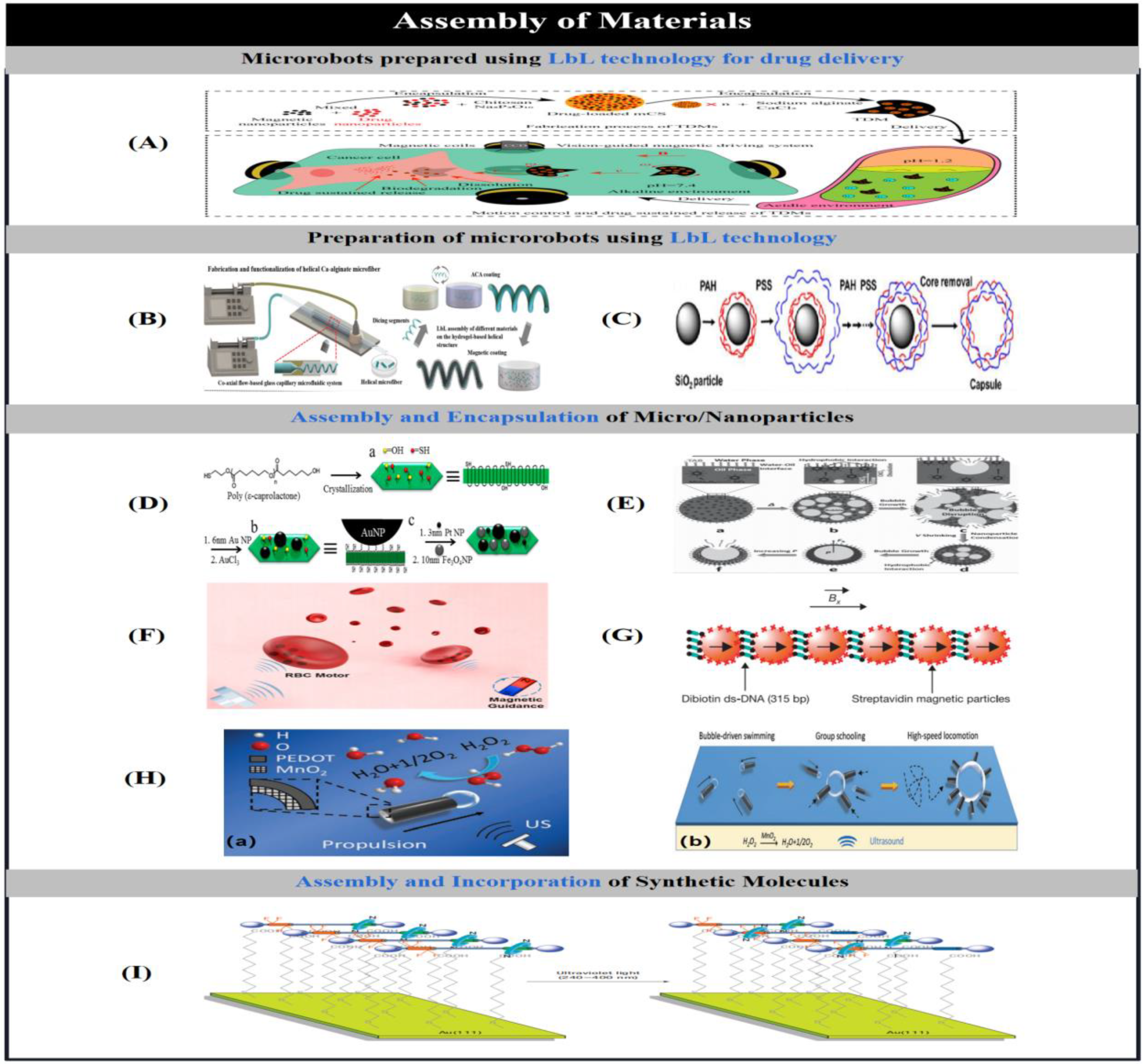
Wu et al. [152] used layer-by-layer deposition instead of electrodeposition to fabricate microtubular motors after thin film template-assisted electrodeposition. Two oppositely charged biodegradable materials, chitosan and sodium alginate, were alternately deposited on a nanoporous film, followed by assembly of platinum nanoparticles into the film nanopores, and nanotubes with catalytic platinum layers on the inner wall were obtained when the film was dissolved. Such nanotubes, formed by layer-by-layer assembly, can be used both as automated motors and as smart payloads capable of drug loading, targeted delivery and remote release in the vicinity of tissues and cells in the living body. However, when targeted drug delivery is actually performed, the acidic conditions caused by tumours make drug-loaded microtubules less effective for treatment. To address this problem, Wu et al. [63] designed a bilayer drug-loaded microrobot (TDM) with an outer layer of calcium alginate hydrogel and an inner layer of magnetic chitosan microspheres (mCS).The TDM delivered the drug-loaded mCS to a predetermined location along the expected route under the action of a visually guided magnetic actuation system. Under acidic conditions, the outer layer of the TDMs was able to protect the mCSs, whereas under alkaline conditions, the calcium alginate hydrogel dissolved at an appropriate rate, allowing for continuous release of the mCSs (Figure 7A). Subsequently, to further improve the efficiency of targeted drug delivery, Liu et al. [57] combined microfluidic synthesis, polyelectrolyte complexation and surface-coated magnetic nanomaterials to prepare a magnetic microrobot with a multilayered capsule spiral structure, which not only has superior loading capacity but can also release the capsule in a controllable manner (Figure 7B). This was done as follows: the spiral structure of the microrobot was first fabricated from calcium alginate microfibres using a coaxial capillary microfluidic system, then wrapped with a polyelectrolyte complex membrane and surface-modified with magnetic nanoparticles. After assembling the multifunctional units in stepwise layers, the helical structure is transformed into a helical capsule. The helical microrobot is not only capable of rotational movement under a 6-degrees-of-freedom electromagnetic drive system with different frequencies, but also has the ability to respond to ionic stimuli due to the presence of a semi-permeable membrane that allows the controlled release of a triggering charge under ionic stimuli.
The LbL technique can be used to fabricate not only tubular and helical micromotors, but also Janus micromotors. For example, Wu et al. [153] fabricated Janus capsule motors partially coated with platinum nanoparticles using template-assisted hierarchical assembly and microprinting combined with microprinting (particle capture) (Figure 7C). Five layers of oppositely charged polystyrene sulfonate (PSS)/polyallylammonium hydrochloride (PAH) were deposited on the surface of the silica template, which was then physically contacted with a stamp loaded with platinum particle ink on top of the substrate. Subsequent removal of the silica template results in a hollow capsule partially coated with platinum particles. The asymmetric movement of the platinum particles and the hollow structure enable the generation of directional forces and encapsulation of the drug. Loading and release of the drug can be achieved by adjusting the permeability of the capsule using an organic solvent, and can be magnetically controlled by applying a magnetic material to the wall of the capsule.

2.5.2. Assembly and Encapsulation of Micro/Nanoparticles

Another approach to making Janus micromotors uses the asymmetric assembly of nanoparticles, which can provide the directional thrust required for motion.Dong et al. [154] fabricated micromotors by directed self-assembly of nanoparticles on a single-crystal polymer of α-hydroxyl-ω-thiol-terminated polycaprolac-tone (HO-PCL-SH) (PSC) on oriented self-assembled nanoparticles to fabricate micromotors (Figure 7D). Due to the presence of a large number of thiols and hydroxyl groups on the surface of the single-crystal polymer, metal nanoparticles can be implanted into the single-crystal polymer using interactions between gold, iron tetraoxide and platinum nanoparticles and functional groups. Platinum nanoparticles can degrade hydrogen peroxide solutions to make single-crystal polymers flow in solution, while gold and iron tetraoxide particles can make them move directionally in the presence of a magnetic field. The polymerised oral cells are nano-sized bowl-like structures formed by controlled deformation of polymeric vesicles, whose stable nano-lumens and tightly controlled openings can act as physical traps for the nanoparticles, and when the nanoparticles are active, they can morphologically transform the oral cells into nanoreactors. Mou et al. [12] demonstrated the magnetic modulation of micromotors consisting of pot-shaped hollow manganese ferrite particles and the method of assembling nanoparticles using growth bubble templates. In an oil droplet consisting of trichloromethane and hexane, nanoparticles consisting of hydrophobic manganese ferrite with oleic acid are assembled into a densely packed layer of particle shells due to hydrophobic interactions between the particle surfaces. As the encapsulated oil droplets are continuously vaporised to form high-pressure bubbles, the compact shell layer ruptures and a single hole is formed in the shell, resulting in the formation of an asymmetric jug-shaped micromotor (Figure 7E).
Wilson et al. [39] achieved automated locomotion by selectively trapping catalytically active platinum nanoparticles in the nanocavity of oral cells, which allowed the oral cells to catalyse the decomposition of hydrogen peroxide to form a rapid discharge and generate a propulsive force. In addition to assembling platinum nanoparticles into micromotors, Wu et al. [155] directly converted red blood cells into functional micromotors, allowing them to function during acoustic actuation and magnetic guidance. By loading iron tetroxide nanoparticles into the erythrocytes, the asymmetric distribution of iron tetroxide particles within the cells creates a net magnetisation such that magnetic alignment and deceleration occur when driven by acoustic waves (Figure 7F). Dreyfus et al. [156] described a linear chain of colloidal magnetic particles attached to haemoglobinocytes as flexible artificial flagella (magnetic particle assembly) by DNA attachment. The flagellum would be aligned with an external homogeneous magnetic field and actuated by the oscillating action of a transverse magnetic field.The actuation induces the generation of a beating pattern to enable the whole structure to achieve motion, and the speed and direction of motion can be controlled by adjusting the magnetic field (Figure 7G).
In addition to building microrobots by assembling nanoparticles, it is also possible to assemble prepared particles into other structures in response to external stimuli. For example, Palacci et al. [157] synthesised photoactivated colloidal particles in suspension by non-equilibrium forces that can form, break, explode and reorganise. The light-activated particles were induced to produce osmotic and light-transmissive effects, thereby stimulating and coupling the self-propulsion and mutual attraction of the particles, allowing these particles to assemble into two-dimensional active crystals. Subsequently, Lu et al. [6] proposed a method for the rapid growth and movement of dandelion-like microclusters composed of catalytic tubular microengines. The self-generated bubbles of the microtubes oscillate under the action of ultrasound waves, allowing the microcluster to overcome the resistance created by a large number of disordered bubbles within a single cell (Figure 7H-a). Driven by ultrasound, individual manganese dioxide tubular micromotors, headed by self-generated oxygen bubbles, rapidly float in a surfactant-free hydrogen peroxide solution, and a large bubble nucleus formed by the fusion of multiple micro-bubbles is excited by acoustic waves and generates oscillations, resulting in locally enhanced acoustic fields that attract more individual micromotors to cluster around them, forming dandelion-like micro-clusters (Figure 7H-b).

2.5.3. Assembly and Incorporation of Synthetic Molecules

In addition to using self-assembly of materials to create the desired structure, it is also possible to create the desired component in a microrobot by incorporating it into another material [158]. Vicario et al. [94] incorporated manganese peroxidase mimicry into a molecular system by covalent conjugation to allow it to convert chemical energy to achieve actuation.Zhang et al. [159] used an engineered molecular assembly and synergistic fabrication of an autokinetic motor driven by a rapid degradation reaction of the polymer poly(2-ethylcyanoa-crylate) (PECA). Micron-sized anion exchangers with PECA adsorbed on the porous structure were semi-coated with poly(methyl methacrylate), and hydroxide released during ion exchange induced the degradation of PECA at the uncoated end, and the resulting ethanol was able to create a surface tension gradient that propelled the particles forward.
In general, photoisomerised molecules of azobenzene can be used in the development of light-driven motors to modify the surface of the particles, where the photoisomerised molecules create an interfacial tension gradient when irradiated with asymmetric light, resulting in net mass transfer of microscopic droplets and nanoparticles. Abid et al. [160] described polymeric nanoparticles coated with azobenzene with a diameter of 16 nm, where the dye grafted on the nanoparticles could act as molecular drivers (photoisomerised monomolecular layers correcting the surface of the substrate): its photoisomerisation provides sufficient mechanical energy to drive the particles to move straight towards the region of lowest intensity in an aqueous medium at a speed of 15 um/sec. Based on the reversible cis-trans isomerisation of the azobenzene molecule, the directional movement of droplets modified with the azobenzene molecule on the surface of the substrate can be achieved by reversible control of light [161]. Similarly, Berna et al. [162] described the directed movement of miniature droplets on a photoresponsive surface consisting of a monolayer of wheeled alkane molecular shuttles (Figure 7I). The millimetre-scale directional transport of droplets on the surface was achieved by using the Brownian motion of stimulus-responsive rotaxanes (molecular shuttles) to expose or hide halothane residues and thus change the surface tension.
Another application of light-driven micromotors is to induce controlled motion in large objects by implanting them in liquid crystal elastomer films. For example, Vicario et al. [163] introduced a molecular motor with a right-handed helical structure, where the rotor site controls the direction of rotation of the motor and there is a single stereocentre at the rotor site, and the carbon-carbon double bond in the central structure acts as an axis, allowing the micromotor to induce microrobotics to rotate on a liquid crystal film in the presence of light. Subsequently, Camacho-Lopez et al. [164] dissolved nitrogen-containing dyes rather than covalently attaching them to liquid crystal elastomers (assembling the microrobots on the surface of liquid crystal elastomers). When irradiated with non-uniform visible light, its mechanical deformation becomes very pronounced (compared to before), and this light-induced rapid deformation allows the liquid crystal elastomer to interact with its environment in a novel way. When the liquid crystal elastomer with a reference dye floating on the surface of the water is irradiated with light from above, it exhibits a behaviour away from the light.

2.6. Biohybrid Technique

Natural systems themselves can provide a variety of microscale motors such as F1-adenosine triphosphate synthase, kinesin, myosin, etc. These natural micromotors can convert the chemical energy in the surrounding medium into the mechanical energy required for their own movement. In addition, mobile units such as bacteria and muscle joints can also achieve self-powered motion in low Reynolds number fluids. Combining the biological properties of natural motors with man-made molecules opens up new possibilities for the fabrication of micro- and nanorobots. This section describes the use of single biomolecules and micro-units for the fabrication of micro- and nanorobots.

2.6.1. Use of Biological Molecules.

Biomolecules can be assembled together with artificial components to form hybrid microsystems.Song et al. [17] constructed a targeted drug delivery microrobot for cancer cell therapy by attaching an azobenzene photo-thermo-responsive material to the carboxyl groups on the surface of a three-microbead microrobot via a strong covalent bond. The microrobot is not only magnetic but also has good cytocompatibility at higher concentrations (200ug/ml). After the microrobot reaches the target site under the action of a magnetic field, it releases the drug under the photothermal action induced by near-infrared light. Liu et al. [34] described a stable DNA nanorobot (TDA) (Figure 8A-a) capable of undergoing controlled conformational changes in response to stimulation of epithelial cell adhesion molecules specifically expressed in the tumour cell cycle. Although TDA undergoes localised distortion during folding, its overall structure remains highly stable and TDA has lower cytotoxicity and target specificity. As a result, TDA not only effectively resists nuclease catalysis, but also has the ability to precisely target EpCAM-positive cells (Figure 8A-b). On this basis, Sengupta et al. [165] introduced an adenosine triphosphate-independent surface-immobilised enzyme that can act as a self-driven micropump in its respective substrate. This surface-immobilised enzyme (catalase, lipase, etc.) is self-driven by the fluid density gradient resulting from the catalytic reaction, and the speed of the micropump increases with substrate concentration and reaction rate.
In order to enable better in vivo application of microrobots, in the current environment catalase is usually used instead of inorganic catalysts to power the microrobots to achieve locomotion in hydrogen peroxide solution.Sanchez et al. [166] covalently bound catalase to convoluted microtubule peritoneum to construct a self-propelled hybrid microengine. Positively generated bubbles generate drag forces to rotate them, allowing them to move in low concentrations of hydrogen peroxide fuel. Taking advantage of this property, Orozco et al. [167] introduced a novel micromotor-based water quality testing strategy based on the change in propulsion behaviour of the engineered biocatalytic micro-swimmers in the presence of aquatic pollutants (Figure 8B).

2.6.2. Use of Motile Units

It is often difficult to use biological motors outside the cell, so intact motile cells are used as actuators for microsystems.Zhang et al. [32] were the first to use intact neutrophils to construct a microrobot (neutrobot) (Figure 8C). The neutrophils constructed the microrobot by phagocytosing E. coli-coated drug-loaded magnetic nanogels.The wrapping of the E. coli film not only enhances the phagocytosis efficiency, but also prevents drug leakage within the neutrophils. Under the influence of the rotating magnetic field, the neutrophil robots have controlled movement behaviour within the blood vessels and will actively accumulate in the brain, and then cross the blood-brain barrier through the positive chemotaxis direction of the inflammatory factor gradient to reach the region where the tumour cells are located to release the drug and inhibit the value added of the tumour cells. Based on the same principle, Al-Fandi et al. [33] reported a new method for self-detection of tumour cells using living nanorobots. These living nanorobots are a non-pathogenic E. coli strain equipped with a naturally synthesised biological nanosensing system that achieves movement driven by a chemical gradient in the medium, and the nanosensing system has an affinity for the angiogenic factor VEGF, which is over-expressed by cancer cells. Thus, selective targeting of tumours can be achieved using swimming E. coli as self-navigating microrobots and drug delivery vehicles.
In addition to achieving movement in response to external stimuli, bio-hybrid microrobots can also rely on their own deformability to achieve movement. For example, Magdanz et al. [168] presented a miniature bio-based robot consisting of mobile sperm cells and magnetic microtubules. The microrobot does not rely on any toxic fuel and moves only by the propulsion of the cell flagellum. In addition, the magnetic microtubules, which are formed from convoluted films, contain lumens that can be used to capture cells and guide the sperm to move in the presence of an applied magnetic field. Meanwhile, Williams et al. [169] introduced a micro-scale series of bio-hybrid swimmers consisting of polydimethylsiloxane filaments with a stiff and short head and a long and thin tail. Actuation was achieved by selectively culturing cardiomyocytes in the tail and using the cardiomyocytes to contract or deform the filaments.
Due to their high biological adaptability, biohybrid microrobots have been widely used in biomedical applications [15,25,170,171]. For example, Xing et al. [25] constructed a biological microrobot (AI microrobot) from Magnetospirillum magneticum (AMB-1) and indocyanine green nanoparticles (Figure 8D), where the former enables the microrobot to move to the tumour area under the effect of internal hypoxia and applied magnetic field effect to move to the tumour area, and the latter can be used as a fluorescent imaging agent and photothermal therapeutic agent. Under the irradiation of near-infrared light, the microrobot will continuously migrate to the internal hypoxic region of the tumour through the photothermal therapy effect, effectively eradicating the solid tumour. Based on the same principle and purpose, magnetic nanoparticles and nanoliposomes loaded with photothermal agents and chemotherapeutic molecules were integrated into E. coli with 90% efficiency by Akolpoglu et al. [171] to form a bacterial biohybrid (Figure 8E). This biohybrid microrobot not only retained its original motility but, under the influence of an applied magnetic field, was able to navigate through the biological matrix and colonise the tumour spheroids, subsequently releasing the drug on demand when stimulated with near-infrared light. In addition to targeted drug delivery, bio-hybrid microrobots can also be used for cell manipulation. Shi et al. [15] provided microbial cells with an artificial extracellular matrix by applying a monolayer of alginate hydrogel around microbial cells doped with ferric tetroxide nanoparticles, resulting in the formation of algal magic cells (alg-mag cells) by uniformly distributing ferric tetroxide particles throughout the hydrogel shell. artificial extracellular matrix (Figure 8F).

2.7. Use of Original Materials

In addition to the various preparation methods mentioned above, some unmodified natural materials can be used directly as micromolecules. Cyclodextrins (CDs), as an amylase-degradable host molecule, are capable of combining with surfactants, alkanes, alkylamines, aliphatic alcohols and aromatic compounds to form supramolecular compounds.Xiao et al. [35] constructed enzyme-responsive nanosystems through host-guest interactions, where the complexation of CDs with surfactants forms a variety of nanostructures such as vesicles and microtubules. These supramolecular structures are capable of loading water-soluble molecules or functional nanoparticles and can be released on demand in the presence of α-amylase. In addition to the use of biomolecules, naturally occurring metal oxides can be used to directly construct micromotors.Mushtaq et al. [13] reported the catalytic degradation of organic compounds using the magnetoelectric properties of core-shell nanoparticles composed of cobalt ferrite-bismuth ferrite (CFO-CBO). By combining the magnetostrictive property of CFO with multiferroic BFO to fabricate micromotors capable of responding to magnetoelectric stimulation, they were able to degrade organic pollutants by an advanced oxidative process in the presence of an applied magnetic field, without the need for additional sacrificial molecules or catalysts for water purification.
The use of natural materials to construct microrobots can be used to drive the movement of particles, in addition to using the magnetic properties of natural materials and interactions between material molecules to achieve actuation, as well as the natural photosensitive properties of natural materials. For example, Hong [172] and Ibele [173] et al. used photosensitive materials (titanium dioxide (Figure 8G) and silver chloride (Figure 8H)), which can create a concentration gradient in the surrounding local environment when stimulated by light, to fabricate microsystems. The movement of the microrobots is based on a light-induced self-diffusion electrophoresis mechanism which, when irradiated with UV light, creates a concentration gradient around the particles, driving them in the direction of the gradient. Similarly, in response to UV light stimulation, Wentao et al. [174] caused the chemical equilibrium of the silver phosphate particle system itself to be perturbed by the addition or removal of ammonia, resulting in rapid transitions between the two population behaviours of repulsion and aggregation. Based on light-driven micromachines, which are usually made of materials containing metallic segments, Villa et al. [28] introduced a metal-free tubular micromotor based on graphitic carbon nitride, which can be actuated by adjusting the switch of the light source. Under visible light irradiation, the micromotor achieves motion through a photocatalytically induced bubble recoil mechanism without the need to incorporate metal parts or biomolecules into its structure.
In addition, the electrochemical properties of natural materials can also be used to construct micromotors. In general, bipolar electrochemistry enables the actuation of a microrobot by inducing asymmetric reactions at both ends of the particles.Loget et al. [175] introduced a mechanism based on bipolar electrochemistry using dynamic bipolar self-regeneration to control the motions of metallic microrobots. Metals are deposited at both ends of the substrate by electrodeposition so that, under the action of an applied electric field, different redox reactions occur at the two ends of the substrate, with the metal at one end being deposited at the same time as the metal at the other end is dissolved to achieve actuation (Figure 8I). Based on the same principle, Loget et al. [176] used a conductive material under the action of an electric field to induce spatially separated redox reactions that would generate asymmetric bubbles at both ends of the metal to achieve controlled actuation of the microrobot (bipolarisation-induced asymmetric bubble generation), and converted the linear motion into a rotational motion based on the redox reactions and the specific design of the mechanism. On this basis, Bouffier et al. [177] increased the speed of movement of bubble-driven microrobots using hydroquinone solution. This is due to the fact that the redox potential of hydroquinone is lower than that of water, causing the microrobots to be ejected at only one end of the microrobots, resulting in higher speeds.

3. Stimulus-response mechanisms and applications of micro/nanobots

Therefore, in order for the micro- and nanorobots produced by the above method to be used in various conceivable scenarios, it is necessary to understand the stimulus-response mechanism of the micro- and nanorobots, and then to establish a reasonable driving method so that they can move to the target position. To date, micro-mechanisms with different stimulus-response mechanisms have been developed by improving the physico-chemical properties of microrobots. To provide a visual overview, Table 2 lists the microrobots that achieve motion based on different stimulus-response mechanisms. In general, microrobots can move in response to various stimuli such as heat, light, pH, ultrasound, magnetic field, biological and ionic. This section describes the different stimulus-response mechanisms and their application scenarios that enable microrobots to move.

3.1. Thermal Stimulus Response Mechanisms

Typically, thermally driven micromotors consist of at least one temperature sensitive material. To date, there are two common types of thermally driven micromotors: polyester fibre poly(N-isopropylacrylamide) (pNIPAM) [52,59,60,61,180], and liquid crystal elastomers (LCEs) [181]. The mechanisms of motion of these two thermally driven micromotors are quite different, with polyester fibres achieving actuation through morphological changes (expansion and de-expansion), whereas the motion of LCEs is due to heterogeneity or disorder in the structure of the particles.
Polyester fibres, the most common type of thermosensitive hydrogel, have a much lower critical solution temperature. In an aquatic solution, changes in particle solubility due to temperature changes can lead to changes in the morphology of the polyester fibres (Fig 9A-a). If the temperature exceeds the minimum critical solution temperature, the polyester fibres will precipitate in the aquatic environment due to the breaking of hydrogen bonds, changing their morphology to a contracted state [60]. To date, polyester fibres can be used to control the direction and speed of movement of thermosensitive polyester fibre-based micromotors by exploiting the fact that they are more sensitive to changes in temperature and can be deformed by the action of external thermal stimuli (Figure 9B) [52,180,182]. For example, Fiedler et al. [52] achieved a reversible braking system for micromotors by controlling small changes in temperature. When Janus particles, partially coated on the outside with thermosensitive polyphosphazenes, were placed in an aqueous solution containing hydrogen peroxide, the particles expelled bubbles and moved rapidly forward due to fuel degradation. When a small change in temperature occurs, the change in polymer conformation modulates the rate of bubble generation, resulting in greater acceleration/deceleration of the micromotor. Similarly, Yoshida et al. [182] enabled a micro-swimmer to sense thermal stimuli from the external environment and thus control its own motion by incorporating a thermosensitive hydrogel into a double-layered micro-spiral swimmer (Figure 9C). In addition, polyester fibre-based thermal micromotors have been applied in many fields such as cancer therapy (Figure 9D) [60], drug delivery (Figure 9E) [61], tracking [59,60], in vivo imaging [59,60], and so on. Due to the structural heterogeneity and disorder of LCEs at different temperatures, LCEs can undergo phase transition or generate bending under the effect of thermal stimulation from the surrounding environment (Figure 9A-b). Based on the thermal bending properties of LCEs, del Pozo et al. [181] fabricated microactuators using liquid crystal photoresists with highly crosslinked networks. The microactuators are not only capable of controlled deformation, but also have unique polarisation colours that allow them to be used for identification and reporting, thus allowing them to be used in the construction of sensors and miniature anti-counterfeiting devices (Figure 9F).

3.2. Light Stimulus Response Mechanisms

Light-driven microrobots are microrobots that are sensitive to external light stimuli. Depending on their composition and light response mechanism, light-driven microrobots can be divided into three main categories:
(i)consists of photosensitive units, such as azobenzene or o-nitrobenzene [17], which are induced by light, causing bond breaking/structural decomposition of the photosensitive units, thereby converting the optical momentum into the force required to move the micromotor [20] (Figure 10A-a). For example, Bozuyuk et al. [20] prepared magnetic double-helix microswimmers with a diameter of 6 μm and a length of 20 μm in the form of magnetic polymer nanocomplexes using two-photon 3D printing of natural derivatives of chitosan, and attached amino groups to the adriamycin-modified swimmers via photocleavage. The micro-swimmers could release adriamycin with an efficiency of 60% in 5 minutes under the induced effect of light and could be precisely controlled under the effect of an applied rotating magnetic field. The incorporation of chitosan enhances the bioadaptability and biodegradability of the microswimmer, allowing it to degrade rapidly to a non-toxic product (204 h) under relevant physiological conditions. In addition, the amount of drug released over time can be varied by controlling the light-induced mode, which causes the drug release to stop (Figure 10B-a).
(ii) consists of thermo-responsive hydrogels and liquid-crystal elastomers [16,18] which, under the action of photothermal heating stimuli, cause the structure of the thermo-responsive materials to deform (expansion/contraction/disorder/bending), leading to the realisation of movement by the microrobot (Figure 9A). Inspired by the primitive human hand, Martella et al. [18] designed a micro-equivalent capable of capturing trace elements (Figure 10C-a). The light-sensitive micromanipulator can not only be remotely controlled under the effect of light stimulation, but can also create conditions in its environment that automatically trap particles according to its own optical properties. By incorporating liquid crystal elastomers into the micromanipulator and exploiting the photothermal sensitive properties of the soft material, the micromanipulator was able to achieve finger movement under the stimulation of ambient light alone.
(iii) consists of a semiconductor with a suitable energy band gap, which, under the catalytic action of light, undergoes a corresponding oxidation/reduction reaction, resulting in the movement of the micromotor [19] (Figure 10A-b). a magnetic microspiral robot consisting of tetraoxo ferric iron trioxide-titanium dioxide magnetic microspiral robot, which can effectively degrade organic pollutants in water when driven by UV visible light (Figure 10D-a). Under the stimulation of visible light, it could remove RhB dye from water within 75 min and achieve 97% degradation efficiency. Meanwhile, when the microrobot was subjected to photocatalytic degradation (directional control) with an applied continuous magnetic field, it could degrade organic pollutants in water within 40 min with 99% decontamination efficiency.
To date, light-driven micromotors have been widely used in many applications such as drug delivery (Figure 10B-b) [17,21,22,23,24,25,27], microwalkers (Figure 10C-b) [16], fabrication of flexible electronic devices [26], and environmental remediation (Figure 10D-b) [28].

3.3. Acoustic Stimulus Response Mechanisms

Ultrasound, as an important external stimulus that enables microrobots to move, has enabled microrobots to be widely used in the biomedical industry for two reasons:(i) Ultrasound is safe, minimally invasive and biocompatible. (ii) By modulating the ultrasound beam/force, it is possible to precisely localise tissues at depths deeper than the micro- and nanoscale. As one of the important means to propel micro- and nanorobotics, ultrasound can not only move particles by generating longitudinal forces, but also by inducing mechanical forces/local thermal effects to move particles [2]. Under the stimulation of ultrasound, the driving mechanism of microrobots can be mainly classified into two types: (i) Cavitation effect (Figure 11A-a). The so-called cavitation effect refers to the formation, oscillation, growth, contraction and collapse of bubbles (cavities) under the action of an ultrasonic field. Tiny bubbles stimulated by alternating periodically fluctuating ultrasound waves generate high temperature and pressure at the moment of bubble collapse, creating a localised high energy fraction that triggers physicochemical changes. For example, Lu et al. [6] proposed a method for the rapid growth and movement of dandelion-like microclusters composed of catalytic tubular microengines. The self-generated bubbles of the microtubes oscillate in the presence of ultrasound waves, allowing the microcluster to overcome the resistance created by a large and disorganised number of bubbles within a single cell. Driven by ultrasonic waves, individual manganese dioxide tubular micromolecules, headed by self-generated oxygen bubbles, rapidly float in a surfactant-free hydrogen peroxide solution, and a large bubble nucleus formed by the fusion of multiple microbubbles is excited by acoustic waves and generates oscillations, resulting in locally enhanced acoustic fields that attract more individual micromolecules to aggregate around them, forming dandelion-like microclusters. Subsequently,Based on the fact that different types of micromotors cluster in different regions (Figure 11B-a), Xu et al. [7] used this property to complete the classification of different types of nanomotors (Figure 11B-b). (II) Acoustic flow effect [3] (Figure 11A-b). The acoustic flow effect is based on the absorption of acoustic waves by the fluid, which generates a driving force and at the same time promotes the generation of an acoustic pressure gradient, thus accelerating the heat and mass transfer process.
So far, acoustically driven microrobots have been widely used in many scenarios, such as targeted drug delivery [2,3,7], delivery and differentiation of neuron-like cells (Figure 11C) [5], cluster control [6,7], and so on. For example, to reduce drug resistance due to lactic acidosis induced by tumour tissue, Meng et al. [2] developed an acoustically driven alkaline microrobot (AN-DSP) consisting of PLGA nanoparticles containing adriamycin (DOX), sodium carbonate and perfluorocarbons (PFCs) to restore lactic acidosis-induced drug resistance. The AN-DSP was able to rapidly respond to external ultrasound stimulation and rapidly release sodium carbonate to neutralise lactic acidosis, thereby improving DOX sensitivity in vitro and in vivo. In response to external ultrasound stimulation, AN-DSP was able to autonomously accumulate in tumour tissue through enhanced permeability and retention effects, thereby specifically disrupting the acidic environment of tumour tissue and ultimately limiting tumour growth with minimal side effects (Figure 11D-a). Subsequently, to further reduce the stimulus response time and accelerate drug release, Darmawan et al. [4] used helical micromotors prepared by monolayer self-folding technique as a controlled drug release system, which allowed efficient drug release under the manipulation of an applied magnetic field. The helical micromotor was capable of rapidly changing shape in response to proton/non-proton stimulation and was able to follow a predetermined path to reach the target site under the action of a rotating magnetic field generated by an electromagnetic drive system, followed by acoustic stimulation to release a non-covalently bound anticancer drug in a very short time (Figure 11D-b).

3.4. pH Stimulus Response Mechanisms

The driving mechanisms of pH-stimulus responsive micromotors can be divided into two main categories based on the pH-sensitive materials:
(i) pH-induced hydrolysis of covalent bonds such as imine bonds, ester bonds, ligand bonds, acetal/ketone bonds, etc. at the pH-sensitive sites of the microrobots (Figure 12A-a), which induces the decomposition of pH-sensitive complexes in the microrobots to achieve movement. For example, Andhari et al. [183] designed a multicomponent magnetic micro- and nanorobot for targeted cancer therapy by chemically binding magnetic iron tetroxide nanoparticles and anti-epithelial cell adhesion molecule antibodies (anti-EpCAM mAb) to multi-walled carbon nanotubes loaded with the anticancer drug adriamycin hydrochloride (DOX). The iron tetroxide nanoparticles have a dual catalytic-magnetic function; the catalytic property allows the micro-nanorobots to be self-driven in complex biofluids; the magnetic property allows the micro-nanorobots to be magnetically navigated in the presence of an external magnetic field, facilitating the release of DOX through the iron tetroxide particle gates into lysosomal intercompartments in human colorectal cancer (HCT16) cells (Figure 12B).
(ii) pH induces expansion or contraction of the microrobots by modulating intermolecular forces such as electrostatic or hydrogen bonding within the pH-sensitive units in the microrobots (Figure 12A-b), resulting in changes in their physical structures. For example, Hu et al. [184] achieved micro-bionic 4D printing of pH-responsive hydrogels in the space-time domain using millisecond laser direct writing. The size of the printed structure is in the micron range (<100 um) and its response time to external stimuli can be reduced to the millisecond range (<500 ms). By exploiting the ability of the hydrogel to expand, contract and twist in response to pH stimuli, the printed microstructures are able to undergo multi-degree-of-freedom shape transformations (Figure 12C). Similarly, the use of reconfigurable micromanipulators is a common means of enabling microrobots to undergo structural deformation. Reconfigurable micromechanisms are highly sensitive to environmental changes, and nanopreparation methods for micromechanisms with complex designs can improve the controllability of their shape changes, such as bending, folding and twisting, while minimising these response times, but it is difficult to prepare three-dimensional structures with a high degree of freedom of shape change at the microscale due to the lack of available materials and effective preparation techniques.Jin et al.[147] introduced a method to enable microrobots to perform multiple degrees of freedom of shape change by printing micromechanisms. 147] introduced a 4D microprinting methodology that achieves 3D-3D shape-changing micromechanisms in a single-material, single-step process by mapping complex stimulus-responsive hydrogels onto arbitrary 3D structures with sub-millimetre features via direct laser writing, and adjusting the cross-linking density, stiffness, and degree of expansion/contraction of the material by programming the exposure dose of a millisecond laser beam to achieve complex 3D structural transformations.
pH-stimulus-responsive micromotors can be widely used not only for targeted cancer therapy [58,63,64,65,66], biosensing (Figure 12D) [67] and shape modification of microrobots [150], [151], but also for environmental improvement. For example, Dekanovsky et al. [62] developed programmable microrobots with polypyrrole (PPy) as the outer functional layer and Pt as the inner catalytic layer to which paramagnetic iron tetraoxide particles were added. The catalytic properties of the Pt layer enabled the microrobots to achieve self-propulsion, and the paramagnetic particles enabled the microrobots to respond to an applied magnetic field to achieve The catalytic properties of the Pt layer enabled the microrobots to achieve self-propulsion, while the paramagnetic particles enabled the microrobots to move in a directional manner in response to an applied magnetic field, thus enabling the microrobots to efficiently remove estrogenic contaminants. As the pH of the water tested changed, the charge on the surface of the microrobots gradually changed, resulting in affinity modulation. As the microrobots moved through the solution, they clustered the estrogenic fibres together and subsequently assembled the estrogenic fibres into a macroscopic network on the functionalised outer surface, resulting in the removal of estrogenic contaminants from the water (Figure 12E).

3.5. Magnetic Stimulation Response Mechanisms

Magnetic fields have been widely used to drive microrobots due to their biocompatibility, remote wireless control, ease of integration and high accuracy. Mechanisms for driving microscale matter using magnetic fields can be classified into the following three main types:
(i) Incorporation of magnetic materials into existing non-magnetic microstructures imparts magneto-electric properties to the composite microstructures to achieve directional control based on the original free motion (Figure 13A-a) [9,11]. For example, Dong et al. [9] infused multiferroic nanoparticle complexes (MENPs) into the helical soft structure of photocurable gelatin-methacryl alcohol (GeIMA)-based hydrogel microswimmers prepared by two-photon lithography, which endowed the microswimmers with magneto-electric properties, and under the effect of magnetic stimulation, enabled the MENPs to transport bioactive chassis to the target location, thereby inducing neuron-like cell differentiation (Figure 13B-a). In addition, the nanoparticle complexes could also convert magnetic field stimuli into electrical signals (Figure 13A-a), which were then used as magnetic-mediated electrical triggers for neuron-like cells. On this basis, Yang et al. [11] achieved reversible motion control of microstructures in ferromagnetic fluids by using dynamic terrain paths formed by superparamagnetic nanoparticles in response to external magnetic stimuli. The dynamic terrain paths change the direction of motion of the micromotor by applying anisotropic resistance to the autonomously moving micromotor. Because the dynamic terrain paths with different directions and lengths can perform rapid reversible assembly under the action of an external magnetic field, thereby controlling the direction and trajectory of the micromotor, the micromotor realises a variety of different trajectory patterns, such as circular, elliptical, semi-sinusoidal and sinusoidal. This motion control strategy eliminates the dependence on external stimuli by adjusting the mode of action and relevant parameters of the external stimuli (Figure 13C).
(ii) Direct use of magnetic fields to drive microrobots composed entirely of magnetic materials (iron, nickel and other magnetic materials) [13,14]. For example, Mou et al. [12] demonstrated the removal of organic pollutants from water by a micromotor composed of pot-shaped hollow manganese ferrite particles. In an oil droplet consisting of trichloromethane and hexane, nanoparticles consisting of hydrophobic manganese ferrite with oleic acid are assembled into a densely packed layer of particle shells due to hydrophobic interactions between the particle surfaces. As the encapsulated oil droplets are continuously vaporised to form high pressure bubbles, the compact shell layer ruptures and a single hole is formed in the shell, resulting in the formation of an asymmetric jug-shaped micromotor. Oxygen molecules produced by the micromotor through catalytic decomposition of hydrogen peroxide preferentially nucleate on the concave surface of the inner layer and grow into bubbles that are continuously ejected through the openings to drive the micromotor, effectively removing the oil droplets (Figure 13D-a).
(iii) Combining magnetic actuation with other modes of actuation to change the direction of particle movement. For example, Ren et al. [8] introduced bubble-based acoustic field-driven microswimmers that can move autonomously in three dimensions and selectively transport individual synthetic glia and mammalian cells in relatively dense populations without the need for labelling, surface modification or impact on the surrounding material. In a MHz acoustic field, the microswimmer is subjected to two forces: a secondary Buell-König force and a locally generated acoustic current drive, the combination of which allows the microswimmer to move freely in free space under the influence of the magnetic field.
To date, the use of magnetic fields to drive microrobots has not only been applied to induced cell differentiation, tumour therapy [14] (Figure 13B-b), cell manipulation [15], locomotion control and environmental remediation [13] (Figure 13D-b), but can also be used to change the shape of microrobots. As a deformable material, origami is characterised by its polymerisability, versatility and tunability. To further expand the applications of origami, Novelino et al. [10] combined the geometric and mechanical properties of bistable Kresling modes with magnetically responsive materials to produce magnetically controlled origami systems. In the presence of an applied magnetic field, the miniature origami robot is able to achieve unconstrained actuation at controlled speeds and can instantly latch onto a shape, enabling shape transformation (Figure 13E).

3.6. Biological Stimulus Response Mechanisms

With the increasing maturity of nanotechnology, the combination of composite particles with biological cells to construct bio-hybrid microrobots has become mainstream. Typically, bio-hybrid microrobots are composed of biodegradable hydrogels (e.g., GelMA) [8,30,31], biological cells ( neutrophils [32]), microbial tissues ( bacteria and algae [33]), and biomolecules (DNA molecules [34]). These components are biodegradable and bioadaptable, which not only allows the micro- and nanorobots to cross the blood-brain barrier in the human body, but also avoids immune tracking, thus enhancing the in vivo application of microrobots [34]. For example, Zhang et al. [32] reported a neutrophil-based microrobot that can actively deliver drug loads to malignant glioma sites in the human body. The neutrophils constructed the neutral robot by phagocytosing E. coli-coated drug-loaded magnetic nanogels, in which the wrapping of the E. coli film not only enhances phagocytosis efficiency but also prevents drug leakage within the neutrophils. Under the influence of a rotating magnetic field, the neutrophils have a controlled movement within the blood vessels and will actively accumulate in the brain and then cross the blood-brain barrier through the positive chemotactic direction of the inflammatory factor gradient to reach the area where the tumour cells are located to release the drug, thus inhibiting the value added of the tumour cells.
The motion mechanisms of biostimulus-responsive micro- and nanorobots can be classified into two categories:(i) enzyme-induced bond cleavage (Figure 14A-a). For example, Wang et al. [31] prepared biodegradable flexible helical microswimmers by two-photon polymerisation using non-toxic photocrosslinked hydrogel methacryloyl (GeIMA) as the material, and enabled magnetic response by modifying the surface of the microswimmers with magnetic nanoparticles. The flexible micro-spiral swimmers were able to spiral forward at a higher forward speed above the step-out frequency compared to conventional rigid spiral robots. In addition, GeIMA have lower cytotoxicity and can be completely degraded by collagen compared to polyethylene glycol acrylate-based microrobots. Furthermore, they can support cell attachment and growth and are gradually digested by enzymes released by the cells during culture (Figure 14B). (ii) Morphological changes in chemically/physically modified biomolecules/bioorganisms/biocells (Figure 14A-b) Liu et al. [34] described a stable DNA nanorobot (TDA) capable of achieving controlled conformational changes in response to stimulation by epithelial cell adhesion molecules specifically expressed in the tumour cell cycle, and the TDA has lower cytotoxicity and target specificity. Thus, TDA is not only effective against nuclease catalysis, but also has the ability to precisely target EpCAM-positive cells. These microrobots have been widely used in drug delivery (Figure 14C) [8,30,35], cell adhesion [31] and early cancer diagnosis [33,34].

3.7. Ionic Stimulus Response Mechanisms

In addition to the use of external stimulus effects, changes in the concentration of some of the major ions in the solution (calcium/sodium ions [57] and lead ions [68]) can also affect the motor behaviour of the microrobots. Ion concentration changes that affect microbot memory can be classified into two types: (i) Ion changes that induce phase changes in the gel or solution in which the microrobots are located (Figure 15A-a) [57]. (ii) Based on ion chelation, ions can induce morphological changes such as expansion/contraction [68] in microrobots (Figure 15A-b). The ion equilibrium state and dynamic ion-responsive behaviour can be regulated by adjusting the ion power and degree of ionisation during the microbot’s motion, which in turn controls the microbot’s motion behaviour. Ion-responsive microrobots have been widely used in drug delivery [57], environmental remediation [68,69] and other fields.
Due to the high stability, good bioadaptability and strong mechanical properties of alginate and chitosan, Liu et al. [57] designed a helically structured microrobot consisting of multilayered alginate/chitosan/alginate composite with iron tetraoxide nanoparticles for drug loading and release. As the ion exchange of calcium and sodium ions in the hydrogel network induces a liquefaction effect, the sol-solution undergoes a phase transition, resulting in the swelling of the microcapsules (Figure 15B). Thus, under the action of ionic stimulation and an external magnetic field, the microrobot delivers the drug to the target site for release.
In addition, ion-stimulated responsive microengines have important environmental applications such as heavy metal detection [68] and carbon dioxide detection [69]. Some heavy metal ions not only cause serious environmental pollution, but also exhibit high toxicity to the human body after bioaccumulation. Lead ions have become one of the most common heavy metal pollutants in daily life due to their non-biodegradability and harmful accumulation in the environment. To achieve the detection of lead ions in aquatic solutions, Liu et al. [68] prepared a lead ion-sensitive microrobot based on poly(NIPAM-co-benzo-18-crown-6-acrylamide). Since a host-guest complex would be formed between the hollow crown ether and the lead ions, the volume of the pNIPAM hydrogel was rapidly swollen, effectively preventing the contaminated lead ion solution from leaking out of the microfluidic channel (Figure 15C). In addition, Mou et al. [69] fabricated a zinc oxide-based micromotor because zinc oxide undergoes self-diffusion electrophoretic motion in the electrolyte in the presence of hydrogen ions provided by carbon dioxide (Figure 15D). Therefore, its high sensitivity to carbon dioxide in water can be used to detect carbon dioxide in water.

3.8. Multi-Stimulus Response Mechanism

Unrestrained microrobots have various applications in different fields, but their small size makes it difficult to precisely manipulate them in their environment, and they can only respond to a single stimulus and are unable to achieve controllable structural deformation in response to different stimuli. In order for multi-stimulus responsive microrobots to respond to a variety of physical or chemical stimuli in complex physiological environments, a variety of responsive materials with different functions are often integrated into a single particle to achieve a variety of different functions. The driving mechanism of multi-stimulus responsive microrobots is the addition of various multi-functional components to the microrobot [170,185] so that it can respond to multiple external stimuli rather than just a single stimulus and generate the appropriate deformation/phase change behaviours to achieve locomotion [186].
For example, Wang et al. [170] first synthesised core-shell Pd@Au nanoparticles with photothermal conversion function by electrodeposition inside Spirulina cells. Subsequently, iron tetraoxide nanoparticles were deposited on the surface of the obtained (Pd@Au)@Sp particles by a sol-gel process, which enabled the microrobots to have a magnetic actuation function. Finally, the anti-cancer drug Adriamycin was loaded on the surface of the composite microrobot to make it chemotherapeutic. This bio-hybrid microrobot not only has an efficient propulsion performance with a maximum speed of 526.2 um/s under a rotating magnetic field, but also has an enhanced synergistic photochemical therapeutic effect. In addition, it can be structurally decomposed into individual particles under near-infrared light irradiation for pH- and near-infrared light-induced drug release (Fig16A-a). Similarly, Akolpoglu et al. [171] incorporated magnetic nanoparticles and nanoliposomes loaded with photothermite and chemotherapeutic molecules into E. coli with 90% efficiency to form a bacterial biohybrid. This biohybrid microrobot not only retained its original motility, but was able to navigate through the biological matrix and colonise tumour spheroids under the action of an applied magnetic field, followed by on-demand drug release under near-infrared light stimulation (Figure 16A-b). However, when targeting the tumour region, the hypoxic conditions in the tumour region can make targeted drug delivery extremely inefficient, resulting in unsatisfactory therapeutic effects. For this reason, Sridhar et al. [187] proposed a two-dimensional poly(heptazine imide) (PHI) carbon nitride particle as a light-driven micro-swimmer that can move at high speeds in multi-component ionic solutions with concentrations up to 5 M and without dedicated fuel. The high ion tolerance of the particles is attributed to the good interaction between the constructional and structural nano-voids of the particles and the nature of the light ions, which contributes to the interaction of the ions in high salt solutions. Nanopores on microswimmers have been used to load the anti-cancer drug adriamycin with a loading efficiency of up to 185%, and controlled on-demand release can be triggered by light under different pH conditions. By exploiting the inherent, environmentally sensitive and light-induced charge storage properties of PHI, the microrobots were able to achieve light-triggered, enhanced adriamycin drug release under hypoxic conditions, enabling targeted therapy in hypoxic regions of tumours.
Currently, multi-stimulus responsive microrobots have been widely used in biomedical applications such as drug delivery [170,171,185,186,187,188] (Figure 16A-c). In addition, because multi-stimulus responsive microrobots are composed of a composite of materials with different functions, their shape can be transformed under the influence of different external stimuli, and thus they can be used to make grippers for capturing substances. For example, Dong et al. [189] fabricated smart microactuators with precise patterns on graphene oxide films using hydrogel microstamping technology, which not only have the ability to change shape programmably, but also respond to a variety of stimuli such as humidity, temperature and light. The programmable micro-actuators have different movement modes, such as mimicking a hawk’s talons to grab a plate or crawling like an inchworm, and can wrap around and grab the axis of the flower according to the flower’s geometry (Figure 16B-a). And by adjusting the intensity and direction of the near-infrared light irradiation, the hydrogel absorbs/loses water, causing the hydrogel structure to deform rapidly in a shorter period of time, thus having the ability to clamp loads (Figure 16B-b) [190].

4. Conclusions and Outlook

This paper provides a comprehensive review of the present advancements in the development of preparation methods and stimulus-response mechanisms for micro- and nanorobots, as well as their applications in biomedicine and environmental remediation. The review encompasses a discussion on the fundamental design of microrobots, including their material compositions and driving mechanisms under diverse stimulus effects. Furthermore, considering the potential applications of micro-scale entities with varying structures in different fields, the paper categorizes and examines the preparation methods and driving mechanisms employed for microrobots with diverse materials and structures.
Microrobots possess remarkable capabilities to perform specific tasks in complex motion environments, owing to their flexible and versatile shapes, controllable motions, and high mechanical strength. They find potential applications in areas such as biological tissue simulation, targeted drug delivery, and cancer diagnosis. However, several bottlenecks still hinder their practical implementation. This paper aims to address the current challenges faced by microrobots and proposes potential solutions to facilitate their practical applications.(i) Some functionalized microrobots are designed with complex synthesis steps, which impede their scalability and commercialization. To overcome this challenge, microrobots can be prepared using 3D laser direct writing technology, which has emerged in recent years and can simplify the synthesis steps.(ii) Certain microrobots exhibit poor sensitivity to specific molecules. Although microrobots with tailored stimulus-response mechanisms can respond to disease-related features within organisms, these features are not exclusively confined to diseased regions, thereby reducing the microrobots’ selectivity in complex environments due to their low sensitivity. To address this issue, the stimulus-response mechanism of the microrobot in the affected area can be analyzed, and its structural design can be optimized to improve sensitivity. Moreover, adopting a reasonable driving method is crucial.(iii) microrobots often suffer from inadequate mechanical properties. While flexible materials can be used for their fabrication, further enhancements are necessary to adapt them for real-life applications. This challenge can be tackled by increasing the cross-linking density while preserving the original deformable structure.(iv) The lack of biocompatibility of materials and chemical fuels used in the fabrication and powering of micro-scale substances restricts their application in living organisms. To overcome this limitation, maximizing the use of reported bio-adaptable materials such as hydrogels, peptides, and bio-organisms can pave the way for developing biologically safe microrobots.(v) In clinical applications, the drug-carrying capacity of a single microrobot is limited due to its small size. To enhance the efficiency of targeted drug delivery, exploring the interactions between individual microrobots and employing the three principles of velocity matching, cohesion, and coherence enable microrobots to move collectively in a coordinated manner. This facilitates stable group movement patterns, thereby enhancing their ability to perform complex tasks more efficiently.(vi) When employing microrobots for targeted drug delivery, in vivo imaging or visualizing the microrobots is crucial for accurate targeting. Establishing a feedback system to monitor and control the movement of microrobots becomes vital to further improve targeting efficiency.By addressing these challenges and implementing the proposed solutions, the practical application of microrobots can be significantly facilitated.

Author Contributions

He Tao: Investigation, conceptualization, writing - Original manuscript. Yonghui Yang:Literature organizing ,Categorizing ,Summarizing Framing. Xue-Bo Chen: Methodology, Conceptualization, Guidance, Writing - Review and Editing.

Acknowledgments

This work was supported by the National Natural Science Foundation of China, under grant number 71571091 and 71771112.

Conflicts of Interest

We declare that we have no known competing financial interests or personal relationships that have appeared to influence the work reported in this paper.

References

  1. Zhou ,Y.;Ye ,M.; Hu, C,; et al. Stimuli-Responsive Functional Micro-/Nanorobots: A Review[J]. ACS nano, 2023.
  2. Meng, X.; Xu, Y.; Lu, Q.; Sun, L.; An, X.; Zhang, J.; Chen, J.; Gao, Y.; Zhang, Y.; Ning, X. Ultrasound-responsive alkaline nanorobots for the treatment of lactic acidosis-mediated doxorubicin resistance. Nanoscale 2020, 12(25), 13801–13810. [Google Scholar] [CrossRef]
  3. Park, J.; Kim, J. Y.; Pane, S.; Nelson, B. J.; Choi, H. Acoustically Mediated Controlled Drug Release and Targeted Therapy with Degradable 3D Porous Magnetic Microrobots. Adv. Healthc. Mater. 2021, 10(2). No. 2001096. [Google Scholar] [CrossRef]
  4. Darmawan, B. A.; Lee, S. B.; Nguyen, V. D.; Go, G.; Nguyen, K.T.; Lee, H.-S.; Nan, M.; Hong, A.; Kim, C.-S.; Li, H.; Bang, D.; Park, J.-O.; Choi, E. Self-folded microrobot for active drug delivery and rapid ultrasound-triggered drug release. Sens. Actuators B Chem. 2020, 324. No. 128752. [Google Scholar] [CrossRef]
  5. Chen, X.-Z.; Liu, J.-H.; Dong, M.; Müller, L.; Chatzipirpiridis, G.; Hu, C.; Terzopoulou, A.; Torlakcik, H.; Wang, X.; Mushtaq, F.; Puigmartí-Luis, J.; Shen, Q.-D.; Nelson, B. J.; Pané, S. Magnetically driven piezoelectric soft microswimmers for neuron-like cell delivery and neuronal differentiation. Mater. Horizons 2019, 6(7), 1512–1516. [Google Scholar] [CrossRef]
  6. Lu, X.; Shen, H.; Wei, Y.; Ge, H.; Wang, J.; Peng, H.; Liu, W. Ultrafast Growth and Locomotion of Dandelion-Like Microswarms with Tubular Micromotors. Small 2020, 16(38). No. 2003678. [Google Scholar] [CrossRef]
  7. Xu, T.; Soto, F.; Gao, W.; Dong, R.; Garcia-Gradilla, V.; Magana, E.; Zhang, X.; Wang, J. Reversible swarming and separation of self-propelled chemically powered nanomotors under acoustic fields. J. Am. Chem. Soc. 2015, 137(6), 2163–2166. [Google Scholar] [CrossRef]
  8. Ren L, Nama N, McNeill J M, et al. 3D steerable, acoustically powered microswimmers for single-particle manipulation[J]. Science advances, 2019, 5(10), eaax3084.
  9. Dong, M.; Wang, X.; Chen, X. Z.; Mushtaq, F.; Deng, S.; Zhu, C.; Torlakcik, H.; Terzopoulou, A.; Qin, X. H.; Xiao, X.; PuigmartíLuis, J.; Choi, H.; Pêgo, A. P.; Shen, Q. D.; Nelson, B. J.; Pané, S. 3D-Printed Soft Magnetoelectric Microswimmers for Delivery and Differentiation of Neuron-Like Cells. Adv. Funct. Mater. 2020, 30(17). No. 1910323. [Google Scholar] [CrossRef]
  10. Novelino, L. S.; Ze, Q.; Wu, S.; Paulino, G. H.; Zhao, R. Untethered control of functional origami microrobots with distributed actuation. Proc. Natl. Acad. Sci. U.S.A. 2020, 117(39), 24096–24101. [Google Scholar] [CrossRef]
  11. Yang, F.; Mou, F.; Jiang, Y.; Luo, M.; Xu, L.; Ma, H.; Guan, J. Flexible Guidance of Microengines by Dynamic Topographical Pathways in Ferrofluids. ACS Nano 2018, 12(7), 6668–6676. [Google Scholar] [CrossRef]
  12. Mou, F.; Pan, D.; Chen, C.; Gao, Y.; Xu, L.; Guan, J. Magnetically Modulated Pot-Like MnFe2O4 Micromotors: Nano-particle Assembly Fabrication and their Capability for Direct Oil Removal. Adv. Funct. Mater. 2015, 25(39), 6173–6181. [Google Scholar] [CrossRef]
  13. Mushtaq, F.; Chen, X.; Torlakcik, H.; Steuer, C.; Hoop, M.; iringil, E. C.; Marti, X.; Limburg, G.; Stipp, P.; Nelson, B. J.; Pane, S. Magnetoelectrically Driven Catalytic Degradation of Organics. Adv.Mater. 2019, 31(28). No. 1901378. [Google Scholar] [CrossRef]
  14. Ge, M.; Xu, D.; Chen, Z.; Wei, C.; Zhang, Y.; Yang, C.; Chen, Y.; Lin, H.; Shi, J. Magnetostrictive-Piezoelectric-Triggered Nano-catalytic Tumor Therapy. Nano Lett. 2021, 21(16), 6764–6772. [Google Scholar] [CrossRef]
  15. Shi, X.; Shi, Z.; Wang, D.; Ullah, M. W.; Yang, G. Microbial Cells with a Fe3O4 Doped Hydrogel Extracellular Matrix: Manipulation of Living Cells by Magnetic Stimulus. Macromol. Biosci. 2016, 16(10), 1506–1514. [Google Scholar] [CrossRef]
  16. Zeng H, Wasylczyk P, Parmeggiani C, et al. Light-fueled microscopic walkers[J]. Advanced Materials, 2015, 27(26), 3883-3887.
  17. Song, X.; Chen, Z.; Zhang, X.; Xiong, J.; Jiang, T.; Wang, Z.; Geng, X.; Cheang, U. K. Magnetic tri-bead microrobot assisted near-infrared triggered combined photothermal and chemotherapy of cancer cells. Sci. Rep. 2021, 11(1), 7907. [Google Scholar] [CrossRef]
  18. Martella, D.; Nocentini, S.; Nuzhdin, D.; Parmeggiani, C.; Wiersma, D. S. Photonic Microhand with Autonomous Action. Adv.Mater. 2017, 29(42). No. 1704047. [Google Scholar] [CrossRef]
  19. Mushtaq, F.; Chen, X.; Staufert, S.; Torlakcik, H.; Wang, X.; Hoop, M.; Gerber, A.; Li, X.; Cai, J.; Nelson, B. J.; Pané, S. On-the-fly catalytic degradation of organic pollutants using magneto-photoresponsive bacteria-templated microcleaners. J. Mater. Chem. A 2019, 7(43), 24847–24856. [Google Scholar] [CrossRef]
  20. Bozuyuk, U.; Yasa, O.; Yasa, I. C.; Ceylan, H.; Kizilel, S.; Sitti, M. Light-Triggered Drug Release from 3D-Printed Magnetic Chitosan Microswimmers. ACS Nano 2018, 12(9), 9617–9625. [Google Scholar] [CrossRef]
  21. Fusco, S.; Huang, H. W.; Peyer, K. E.; Peters, C.; Haberli, M.; Ulbers, A.; Spyrogianni, A.; Pellicer, E.; Sort, J.; Pratsinis, S. E.; Nelson, B. J.; Sakar, M. S.; Pane, S. Shape-switching microrobots for medical applications: the influence of shape in drug delivery and locomotion. ACS Appl. Mater. Interfaces 2015, 7(12), 6803–6811. [Google Scholar] [CrossRef]
  22. Das, S.; Hunter, E. E.; DeLateur, N. A.; Steager, E. B.; Weiss, R.; Kumar, V. Cellular expression through morphogen delivery by light activated magnetic microrobots. J. Microbio. Robot 2019, 15(2), 79–90. [Google Scholar] [CrossRef]
  23. Lee, H.; Choi, H.; Lee, M.; Park, S. Preliminary study on alginate/NIPAM hydrogel-based soft microrobot for controlled drug delivery using electromagnetic actuation and near-infrared stimulus. Biomed. Microdevices 2018, 20(4), 103. [Google Scholar] [CrossRef]
  24. Nguyen, K. T.; Go, G.; Jin, Z.; Darmawan, B. A.; Yoo, A.; Kim, S.; Nan, M.; Lee, S. B.; Kang, B.; Kim, C. S.; Li, H.; Bang, D.; Park, J.O.; Choi, E. A Magnetically Guided Self-Rolled Microrobot for Targeted Drug Delivery, Real-Time X-Ray Imaging, and Microrobot Retrieval. Adv. Healthcare Mater. 2021, 10(6). No. 2001681. [Google Scholar] [CrossRef]
  25. Xing, J.; Yin, T.; Li, S.; Xu, T.; Ma, A.; Chen, Z.; Luo, Y.; Lai, Z.; Lv, Y.; Pan, H.; Liang, R.; Wu, X.; Zheng, M.; Cai, L. Sequential Magneto-Actuated and Optics-Triggered Biomicrorobots for Targeted Cancer Therapy. Adv. Funct. Mater. 2021, 31(11). No. 2008262. [Google Scholar] [CrossRef]
  26. Du, X.; Cui, H.; Sun, B.; Wang, J.; Zhao, Q.; Xia, K.; Wu, T.; Humayun, M. S. Photothermally Triggered Shape-AdapTable 3D Flexible Electronics. Adv. Mater. Technol. 2017, 2(10). No. 1700120. [Google Scholar] [CrossRef]
  27. Kim, D.-i.; Lee, H.; Kwon, S.-h.; Choi, H.; Park, S. Magnetic nano-particles retrievable biodegradable hydrogel microrobot. Sens.Actuators B Chem. 2019, 289, 65–77. [Google Scholar] [CrossRef]
  28. Villa, K.; Manzanares Palenzuela, C. L.; Sofer, Z.; Matejkova, S.; Pumera, M. Metal-Free Visible-Light Photoactivated C3N4 Bubble-Propelled Tubular Micromotors with Inherent Fluorescence and On/Off Capabilities. ACS Nano 2018, 12(12), 12482–12491. [Google Scholar] [CrossRef]
  29. Ceylan H, Yasa I C, Yasa O, et al. 3D-printed biodegradable microswimmer for theranostic cargo delivery and release[J]. ACS nano, 2019, 13(3), 3353-3362.
  30. Terzopoulou, A.; Wang, X.; Chen, X. Z.; Palacios-Corella, M.; Pujante, C.; Herrero-Martin, J.; Qin, X. H.; Sort, J.; deMello, A. J.; Nelson, B. J.; Puigmarti-Luis, J.; Pane, S. Biodegradable Metal-Organic Framework-Based Microrobots (MOFBOTs). Adv. Healthcare Mater. 2020, 9(20). No. 2001031. [Google Scholar] [CrossRef]
  31. Wang, X.; Qin, X.-H.; Hu, C.; Terzopoulou, A.; Chen, X.-Z.; Huang, T.-Y.; Maniura-Weber, K.; Pané, S.; Nelson, B. J. 3D Printed Enzymatically Biodegradable Soft Helical Microswimmers. Adv. Funct. Mater. 2018, 28(45). No. 1804107. [Google Scholar]
  32. Zhang, H.; Li, Z.; Gao, C.; Fan, X.; Pang, Y.; Li, T.; Wu, Z.; Xie, H.; He, Q. Dual-responsive biohybrid neutrobots for active target delivery. Sci. Robot 2021, 6, No. eaaz9519. [Google Scholar] [CrossRef]
  33. Al-Fandi, M.; Alshraiedeh, N.; Oweis, R.; Alshdaifat, H.; Al-Mahaseneh, O.; Al-Tall, K.; Alawneh, R. Novel Selective Detection Method of Tumor Angiogenesis Factors Using Living Nano-Robots. Sensors (Basel) 2017, 17(7), 1580. [Google Scholar] [CrossRef]
  34. Liu, F.; Liu, X.; Shi, Q.; Maffeo, C.; Kojima, M.; Dong, L.; Aksimentiev, A.; Huang, Q.; Fukuda, T.; Arai, T. A tetrahedral DNA nanorobot with conformational change in response to molecular trigger. Nanoscale 2021, 13(37), 15552–15559. [Google Scholar]
  35. Xiao, X.; Xu, Z.; Wang, W.; Sun, S.; Qiao, Y.; Jiang, L.; Yan, Y.; Huang, J. Enzyme-Responsive Molecular Assemblies Based on Host-Guest Chemistry. Langmuir 2021, 37(27), 8348–8355. [Google Scholar]
  36. Xu L, Mou F, Gong H, et al. Light-driven micro/nanomotors: from fundamentals to applications[J]. Chemical Society Reviews, 2017, 46(22), 6905-6926.
  37. Zhao G, Seah T H, Pumera M. External-energy-independent polymer capsule motors and their cooperative behaviors[J]. Chemistry–A European Journal, 2011, 17(43), 12020-12026.
  38. Lee T C, Alarcón-Correa M, Miksch C, et al. Self-propelling nanomotors in the presence of strong Brownian forces[J]. Nano letters, 2014, 14(5), 2407-2412.
  39. Wilson D A, Nolte R J M, Van Hest J C M. Autonomous movement of platinum-loaded stomatocytes[J]. Nature chemistry, 2012, 4(4), 268-274.
  40. Liu R, Sen A. Autonomous nanomotor based on copper–platinum segmented nanobattery[J]. Journal of the American Chemical Society, 2011, 133(50), 20064-20067.
  41. Mou, F.; Kong, L.; Chen, C.; Chen, Z.; Xu, L.; Guan, J. Light-Controlled Propulsion, Aggregation and Separation of Water-FuelledTiO2/Pt Janus Submicromotors and Their “on-the-Fly” Photo-catalytic Activities. Nanoscale 2016, 8, 4976–4983. [Google Scholar] [CrossRef]
  42. Zhou, D.; Ren, L.; Li, Y. C.; Xu, P.; Gao, Y.; Zhang, G.; Wang, W.; Mallouk, T. E.; Li, L. Visible Light-Driven, Magnetically Steerable Gold/Iron Oxide Nanomotors. Chem. Commun. 2017, 53, 11465–11468. [Google Scholar] [CrossRef]
  43. Wang, J.; Xiong, Z.; Zhan, X.; Dai, B.; Zheng, J.; Liu, J.; Tang, J. A Silicon Nanowire as a Spectrally Tunable Light-Driven Nanomotor. Adv. Mater. 2017, 29, 1701451. [Google Scholar] [CrossRef]
  44. Wong, F.; Sen, A. Progress toward Light-Harvesting Self- Electrophoretic Motors: Highly Efficient Bimetallic Nanomotors and Micropumps in Halogen Media. ACS Nano 2016, 10, 7172–7179. [Google Scholar] [CrossRef]
  45. Wang, X.; Sridhar, V.; Guo, S.; Talebi, N.; Miguel-López, A.; Hahn, K.; van Aken, P. A.; Sánchez, S. Fuel-Free Nanocap-Like Motors Actuated under Visible Light. Adv. Funct. Mater. 2018, 28, 1705862. [Google Scholar] [CrossRef]
  46. Baraban L, Makarov D, Streubel R, et al. Catalytic Janus motors on microfluidic chip: deterministic motion for targeted cargo delivery[J]. ACS nano, 2012, 6(4), 3383-3389.
  47. Brown A, Poon W. Ionic effects in self-propelled Pt-coated Janus swimmers[J]. Soft matter, 2014, 10(22), 4016-4027.
  48. Zhang J, Yao Y, Sheng L, et al. Self-Fueled Motors: Self-Fueled Biomimetic Liquid Metal Mollusk (Adv. Mater. 16/2015)[J]. Advanced Materials, 2015, 27(16), 2550-2550.
  49. Srivastava S K, Guix M, Schmidt O G. Wastewater mediated activation of micromotors for efficient water cleaning[J]. Nano letters, 2016, 16(1), 817-821.
  50. Gao W, Pei A, Wang J. Water-driven micromotors[J]. ACS nano, 2012, 6(9), 8432-8438.
  51. Soler L, Magdanz V, Fomin V M, et al. Self-propelled micromotors for cleaning polluted water[J]. ACS nano, 2013, 7(11), 9611-9620.
  52. Fiedler, C.; Ulbricht, C.; Truglas, T.; Wielend, D.; Bednorz, M.; Groiss, H.; Bruggemann, O.; Teasdale, I.; Salinas, Y. Reversible Speed Regulation of Self-Propelled Janus Micromotors via Thermoresponsive Bottle-Brush Polymers. Chemistry 2021, 27(10), 3262–3267. [Google Scholar]
  53. Wei G, Allen P, Renfeng D, Joseph W, et al. Catalytic Iridium-Based Janus Micromotors Powered By Ultralow Levels Of Chemical Fuels[J], Journal of the American Chemical Society, 2014, 136(6), 2276-2279.
  54. Gao W, Uygun A, Wang J. Hydrogen-bubble-propelled zinc-based microrockets in strongly acidic media[J]. Journal of the American Chemical Society, 2012, 134(2), 897-900.
  55. Gao W, D’Agostino M, Garcia-Gradilla V, et al. Multi-fuel driven janus micromotors[J]. Small, 2013, 9(3), 467-471.
  56. Gao, W.; Feng, X.; Pei, A.; Gu, Y.; Li, J.; Wang, J. Seawater-Driven Magnesium Based Janus Micromotors for EnvironmentalRemediation. Nanoscale 2013, 5, 4696–4700. [Google Scholar] [CrossRef]
  57. Liu, Y.; Yang, Y.; Yang, X.; Yang, L.; Shen, Y.; Shang, W. Multi-functionalized micro-helical capsule robots with superior loading and releasing capabilities. J. Mater. Chem. B 2021, 9(5), 1441–1451. [Google Scholar] [CrossRef]
  58. Li J, Angsantikul P, Liu W, et al. Micromotors spontaneously neutralize gastric acid for pH-responsive payload release[J]. Angewandte Chemie International Edition, 2017, 56(8), 2156-2161.
  59. Iacovacci V, Blanc A, Huang H, et al. High-resolution SPECT imaging of stimuli-responsive soft microrobots[J]. Small, 2019, 15(34), 1900709.
  60. Tabatabaei, S. N.; Lapointe, J.; Martel, S. Shrinkable Hydrogel-Based Magnetic Microrobots for Interventions in the Vascular Network. Adv. Robotics 2011, 25(8), 1049–1067. [Google Scholar]
  61. Mou, F.; Chen, C.; Zhong, Q.; Yin, Y.; Ma, H.; Guan, J. Autonomous motion and temperature-controlled drug delivery of Mg/Pt-poly(N-isopropylacrylamide) Janus micromotors driven by simulated body fluid and blood plasma. ACS Appl. Mater. Interfaces 2014, 6(12), 9897–9903. [Google Scholar]
  62. Dekanovsky, L.; Khezri, B.; Rottnerova, Z.; Novotny, F.; Plutnar, J.; Pumera, M. Chemically programmable microrobots weaving a web from hormones. Nature Machine Intelligence 2020, 2(11), 711–718. [Google Scholar]
  63. Chen, W.; Sun, M.; Fan, X.; Xie, H. Magnetic/pH-sensitive double-layer microrobots for drug delivery and sustained release. Appl. Mater. Today 2020, 19, No. 100583. [Google Scholar] [CrossRef]
  64. Li, H.; Go, G.; Ko, S. Y.; Park, J.-O.; Park, S. Magnetic actuated pH-responsive hydrogel-based soft microrobot for targeted drug delivery. Smart Mater. Struct. 2016, 25(2). No. 027001. [Google Scholar]
  65. Wang, X.; Chen, X. Z.; Alcantara, C. C. J.; Sevim, S.; Hoop, M.; Terzopoulou, A.; de Marco, C.; Hu, C.; de Mello, A. J.; Falcaro, P.; Furukawa, S.; Nelson, B. J.; Puigmarti-Luis, J.; Pane, S. MOFBOTS:Metal-Organic-Framework-Based Biomedical Microrobots. Adv.Mater. 2019, 31(27). No. 1901592. [Google Scholar]
  66. Chengzhi, H.; Riederer, K.; Klemmer, M.; Pane, S.; Nelson, B.J. Electrosynthesis of Magnetoresponsive Microrobot for Targeted Drug Delivery using Calcium Alginate. 2016 38th Annual International Conference of the IEEE Engineering in Medicine and Biology Society (EMBC); IEEE, 2016; pp 2111−2114. [CrossRef]
  67. Di, Z.; Zhao, J.; Chu, H.; Xue, W.; Zhao, Y.; Li, L. An Acidic-Microenvironment-Driven DNA Nanomachine Enables Specific ATP Imaging in the Extracellular Milieu of Tumor. Adv. Mater. 2019, 31(33). No. 1901885. [Google Scholar]
  68. Liu, Y. M.; Wang, W.; Zheng, W. C.; Ju, X. J.; Xie, R.; Zerrouki, D.; Deng, N. N.; Chu, L. Y. Hydrogel-based microactuators with remote-controlled locomotion and fast Pb2+-response for micromanipulation. ACS Appl. Mater. Interfaces 2013, 5(15), 7219–7226. [Google Scholar]
  69. Mou, F.; Xie, Q.; Liu, J.; Che, S.; Bahmane, L.; You, M.; Guan, J. ZnO-based micromotors fueled by CO2: the first example of self-reorientation-induced biomimetic chemotaxis. Natl. Sci. Rev. 2021, 8(11). No. nwab066. [Google Scholar]
  70. Wang H, Pumera M. Fabrication of micro/nanoscale motors[J]. Chemical reviews, 2015, 115(16), 8704-8735.
  71. Paxton WF, Kistler KC, Olmeda CC, Sen A, St Angelo SK, Cao Y, Mallouk TE, Lammert PE, Crespi VH. Catalytic nanomotors: autonomous movement of striped nanorods. J Am Chem Soc. 2004 Oct 20;126(41):13424-31.
  72. Fan, D. L.; Zhu, F. Q.; Cammarata, R. C.; Chien, C. L. Manipulation of Nanowire in Suspension by AC Electric Fields. Appl. Phys. Lett. 2004, 85, 4175. [Google Scholar] [CrossRef]
  73. Fan, D. L.; Zhu, F. Q.; Cammarata, R. C.; Chien, C. L. Controllable High-Speed Rotation of Nanowires. Phys. Rev. Lett. 2005, 94, 247208. [Google Scholar] [CrossRef]
  74. Gao, W.; Sattayasamitsathit, S.; Manesh, K. M.; Weihs, D.; Wang, J. Magnetically Powered Flexible Metal Nanowire Motors. J. Am. Chem. Soc. 2010, 132, 14403–14405. [Google Scholar] [CrossRef]
  75. Zhao G, Ambrosi A, Pumera M. Self-propelled nanojets via template electrodeposition[J]. Nanoscale, 2013, 5(4): 1319-1324.
  76. Tanase M, Bauer L A, Hultgren A, et al. Magnetic alignment of fluorescent nanowires[J]. Nano Letters, 2001, 1(3): 155-158.
  77. Gao W, Sattayasamitsathit S, Orozco J, et al. Highly efficient catalytic microengines: template electrosynthesis of polyaniline/platinum microtubes[J]. Journal of the American Chemical Society, 2011, 133(31): 11862-11864.
  78. Zhang, L.; Petit, T.; Lu, Y.; Kratochvil, B. E.; Peyer, K. E.; Pei, R.; Lou, J.; Nelson, B. J. Controlled Propulsion and Cargo Transport of Rotating Nickel Nanowires near a Patterned Solid Surface. ACS Nano 2010, 4, 6228–6234. [Google Scholar] [CrossRef] [PubMed]
  79. Fournier-Bidoz S, Arsenault A C, Manners I, et al. Synthetic self-propelled nanorotors[J]. Chemical Communications, 2005 (4): 441-443.
  80. Ambulo C P, Burroughs J J, Boothby J M, et al. Four-dimensional printing of liquid crystal elastomers[J]. ACS applied materials & interfaces, 2017, 9(42), 37332-37339.
  81. Demirok, U. K.; Laocharoensuk, R.; Manesh, K. M.; Wang, J. Ultrafast Catalytic Alloy Nanomotors. Angew. Chem., Int. Ed. 2008, 47, 9349–9351. [Google Scholar]
  82. Laocharoensuk R, Burdick J, Wang J. Carbon-nanotube-induced acceleration of catalytic nanomotors[J]. ACS nano, 2008, 2(5), 1069-1075.
  83. Zacharia, N. S.; Sadeq, Z. S.; Ozin, G. A. Enhanced Speed of Bimetallic Nanorod Motors by Surface Roughening. Chem. Commun. 2009, 5856–5858.
  84. Suk T C, Vesselin N P, Dimiter N P, Orlin D V, et al. Remotely powered self-propelling particles and micropumps based on miniature diodes[J], Nature materials, 2007, 6(3), 235.0-240.
  85. Wang, W.; Castro, L. A.; Hoyos, M.; Mallouk, T. E. Autonomous Motion of Metallic Microrods Propelled by Ultrasound. ACS Nano 2012, 6, 6122–6132. [Google Scholar] [CrossRef] [PubMed]
  86. Nadal, F.; Lauga, E. Asymmetric Steady Streaming as aMechanism for Acoustic Propulsion of Rigid Bodies. Phys. Fluids 2014, 26, 082001. [Google Scholar] [CrossRef]
  87. Garcia-Gradilla, V.; Orozco, J.; Sattayasamitsathit, S.; Soto, F.; Kuralay, F.; Pourazary, A.; Katzenberg, A.; Gao, W.; Shen, Y.; Wang, J. Functionalized Ultrasound-Propelled Magnetically Guided Nano-motors: Toward Practical Biomedical Applications. ACS Nano 2013, 7, 9232–9240. [Google Scholar] [CrossRef] [PubMed]
  88. Mair L O, Evans B, Hall A R, et al. Highly controllable near-surface swimming of magnetic Janus nanorods: application to payload capture and manipulation[J]. Journal of Physics D: Applied Physics, 2011, 44(12), 125001.
  89. Abbott J J, Peyer K E, Lagomarsino M C, et al. How should microrobots swim?[J]. The international journal of Robotics Research, 2009, 28(11-12), 1434-1447.
  90. Mirkovic, T.; Foo, M. L.; Arsenault, A. C.; Fournier-Bidoz, S.; Zacharia, N. S.; Ozin, G. A. Hinged Nanorods Made Using a Chemical Approach to Flexible Nanostructures. Nat. Nanotechnol. 2007, 2, 565–569. [Google Scholar] [CrossRef] [PubMed]
  91. Jang, B.; Gutman, E.; Stucki, N.; Seitz, B. F.; Wendel-García, P. D.; Newton, T.; Pokki, J.; Ergeneman, O.; Pané, S.; Or, Y.; Nelson, B. J. Undulatory Locomotion of Magentic MultilinkNanoswimmers. Nano Lett. 2015, 15, 4829–4833. [Google Scholar] [CrossRef] [PubMed]
  92. Walter F P, Paul T B, Timothy R K, Yang W, Thomas E M, Ayusman S, et al. Catalytically Induced Electrokinetics For Motors And Micropumps[J], Journal of the American Chemical Society, 2006, 128(46), 14881-14888.
  93. Sanchez S, Ananth A N, Fomin V M, et al. Superfast motion of catalytic microjet engines at physiological temperature[J]. Journal of the American Chemical Society, 2011, 133(38), 14860-14863.
  94. Vicario, J.; Eelkema, R.; Browne, W. R.; Meetsma, A.; La Crois, R. M.; Feringa, B. L. Catalytic Molecular Motors: Fuelling Autonomous Movement by a Surface Bound Synthetic Manganese Catalase. Chem. Commun. 2005, 3936−3938.
  95. Solovev A A, Xi W, Gracias D H, et al. Self-propelled nanotools[J]. Acs Nano, 2012, 6(2), 1751-1756.
  96. Fattah Z, Loget G, Lapeyre V, et al. Straightforward single-step generation of microswimmers by bipolar electrochemistry[J]. Electrochimica acta, 2011, 56(28), 10562-10566.
  97. Solovev A A, Mei Y, Bermúdez Ureña E, et al. Catalytic microtubular jet engines self-propelled by accumulated gas bubbles[J]. Small, 2009, 5(14), 1688-1692.
  98. Solovev A A, Sanchez S, Pumera M, et al. Magnetic control of tubular catalytic microrobots for the transport, assembly, and delivery of micro-objects[J]. Advanced Functional Materials, 2010, 20(15), 2430-2435.
  99. Wei G, Sirilak S, Aysegul U, Allen P, Adam P, Joseph W, et al. Polymer-based tubular microrobots: role of composition and preparation.[J], Nanoscale, 2012, 4(7), 2447-2453.
  100. Zhao, G.; Pumera, M. Concentric Bimetallic Microjets byElectrodeposition. RSC Adv. 2013, 3, 3963–3966. [Google Scholar] [CrossRef]
  101. Liu, L.; Yoo, S.-H.; Lee, S. A.; Park, S. Wet-ChemicalSynthesis of Palladium Nanosprings. Nano Lett. 2011, 11, 3979–3982. [Google Scholar] [CrossRef] [PubMed]
  102. Li J, Sattayasamitsathit S, Dong R, et al. Template electrosynthesis of tailored-made helical nanoswimmers[J]. Nanoscale, 2014, 6(16), 9415-9420.
  103. Manesh, K. M.; Cardona, M.; Yuan, R.; Clark, M.; Kagan, D.; Balasubramanian, S.; Wang, J. Template-Assisted Fabrication of Salt-Independent Catalytic Tubular Microengines. ACS Nano 2010, 4, 1799–1804. [Google Scholar] [CrossRef]
  104. Schuerle, S.; Pane, S.; Pellicer, E.; Sort, J.; Baro, M. D.; Nelson, B. J. Helical and Tubular Lipid Microstructures That Are Electroless-Coated with CoNiReP for Wireless Magnetic Manipulation. Small 2012, 8, 1498–1502. [Google Scholar] [CrossRef]
  105. Loget G, Roche J, Kuhn A. True bulk synthesis of Janus objects by bipolar electrochemistry[J]. Advanced materials, 2012, 37(24), 5111-5116.
  106. Loget, G.; Larcade, G.; Lapeyre, V.; Garrigue, P.; Warakulwit, C.; Limtrakul, J.; Delville, M.-H.; Ravaine, V.; Kuhn, A. Single Point Electrodeposition of Nickel for the Dissymmetric Decoration of Carbon Tubes. Electrochim. Acta 2010, 55, 8116–8120. [Google Scholar] [CrossRef]
  107. Gao, W.; Feng, X.; Pei, A.; Kane, C. R.; Tam, R.; Hennessy, C.; Wang, J. Bioinspired Helical Microswimmers Based on Vascular Plants. Nano Lett. 2014, 14, 305–310. [Google Scholar] [CrossRef]
  108. Baraban, L.; Streubel, R.; Makarov, D.; Han, L.; Karnaushenko, D.; Schmidt, O. G.; Cuniberti, G. Fuel-Free Locomotion of Janus Motors: Magnetically Induced Thermophoresis. ACS Nano 2013, 7, 1360–1367. [Google Scholar] [CrossRef] [PubMed]
  109. Qin, L.; Banholzer, M. J.; Xu, X.; Huang, L.; Mirkin, C. A. Rational Design and Synthesis of Catalytically Driven Nanorotors. J.Am. Chem. Soc. 2007, 129, 14870–14871. [Google Scholar] [CrossRef] [PubMed]
  110. Wang, Y.; Fei, S.; Byun, Y.-M.; Lammert, P. E.; Crespi, V. H.; Sen, A.; Mallouk, T. E. Dynamic Interactions between Fast Microscale Rotors. J. Am. Chem. Soc. 2009, 131, 9926–9927. [Google Scholar] [CrossRef]
  111. Paxton, W. F.; Sundararajan, S.; Mallouk, T. E.; Sen, A. Chemical Locomotion. Angew. Chem., Int. Ed. 2006, 45, 5420–5429. [Google Scholar] [CrossRef]
  112. Micheletto, R.; Fukuda, H.; Ohtsu, M. A Simple Method for the Production of a Two-Dimensional, Ordered Array of Small Latex Particles. Langmuir 1995, 11, 3333–3336. [Google Scholar] [CrossRef]
  113. Hong, Y.; Velegol, D.; Chaturvedi, N.; Sen, A. Biomimetic Behavior of Synthetic Particles: From Microscopic Randomness to Macroscopic Control. Phys. Chem. Chem. Phys. 2010, 12, 1423–1435. [Google Scholar] [CrossRef]
  114. Wheat P M, Marine N A, Moran J L, et al. Rapid fabrication of bimetallic spherical motors[J]. Langmuir, 2010, 26(16), 13052-13055.
  115. Valadares, L. F.; Tao, Y. G.; Zacharia, N. S.; Kitaev, V.; Galembeck, F.; Kapral, R.; Ozin, G. A. Catalytic Nanomotors: Self-Propelled Sphere Dimers. Small 2010, 6, 565–572. [Google Scholar] [CrossRef]
  116. Zhao G, Pumera M. Geometric asymmetry driven Janus micromotors[J]. Nanoscale 2014, 6(19), 11177-11180.
  117. Tierno, P.; Albalat, R.; Sagues, F. Autonomously Moving Catalytic Microellipsoids Dynamically Guided by External MagneticFields. Small 2010, 6, 1749–1752. [Google Scholar] [CrossRef]
  118. Fangzhi M, Chuanrui C, Huiru M, Yixia Y, Qingzhi W, Jianguo G, et al. Self-propelled micromotors driven by the magnesium-water reaction and their hemolytic properties.[J], Angewandte Chemie, 2013, 52(28), 7208-7212.
  119. Zhao Y, Ye D, Wang G C, et al. Designing nanostructures by glancing angle deposition[C]//Nanotubes and Nanowires. SPIE, 2003, 5219: 59-73.
  120. Ghosh, A.; Fischer, P. Controlled Propulsion of Artificial Magnetic Nanostructured Propellers. Nano Lett. 2009, 9, 2243–2245. [Google Scholar] [CrossRef]
  121. Schamel, D.; Mark, A. G.; Gibbs, J. G.; Miksch, C.; Morozov, K. I.; Leshansky, A. M.; Fischer, P. Nanopropellers and Their Actuation in Complex Viscoelastic Media. ACS Nano 2014, 8, 8794–8801. [Google Scholar] [CrossRef]
  122. Ghosh A, Paria D, Rangarajan G, et al. Velocity fluctuations in helical propulsion: How small can a propeller be[J]. The journal of physical chemistry letters, 2014, 5(1), 62-68.
  123. Walker D, Kubler M, Morozov K I, et al. Optimal length of low Reynolds number nanopropellers[J]. Nano letters, 2015, 15(7), 4412-4416.
  124. Schamel, D.; Pfeifer, M.; Gibbs, J. G.; Miksch, B.; Mark, A.G.; Fischer, P. Chiral Colloidal Molecules and Observation of the Propeller Effect. J. Am. Chem. Soc. 2013, 135, 12353–12359. [Google Scholar] [CrossRef] [PubMed]
  125. Gibbs, J. G.; Fragnito, N. A.; Zhao, Y. Asymmetric Pt/Au Coated Catalytic Micromotors Fabricated by Dynamic Shadowing Growth. Appl. Phys. Lett. 2010, 97, 253107. [Google Scholar] [CrossRef]
  126. Yuping He, Jinsong Wu, Yiping Zhao. Designing Catalytic Nanomotors By Dynamic Shadowing Growth[J], NANO LETTERS, 2007, 7(5), 1369-1375.
  127. J. G. Gibbs, Y.-P. Zhao. Design and characterization of rotational multicomponent catalytic nanomotors.[J], Small, 2009, 5(20), 2304-2308.
  128. Huang, W.; Manjare, M.; Zhao, Y. Catalytic Nanoshell Micromotors. J. Phys. Chem. C 2013, 117, 21590–21596. [Google Scholar] [CrossRef]
  129. Yongfeng M, Alexander A S, Samuel S, Oliver G S, et al. Rolled-up nanotech on polymers: from basic perception to self-propelled catalytic microengines.[J], Chemical Society reviews, 2011, 40(5), 2109-2119.
  130. Harazim S M, Xi W, Schmidt C K, et al. Fabrication and applications of large arrays of multifunctional rolled-up SiO/SiO 2 microtubes[J]. Journal of Materials Chemistry, 2012, 22(7), 2878-2884.
  131. Kun Y, Manoj M, Christopher A B, Bo Y, Tina T S, Yiping Z, et al. Nanostructured Scrolls from Graphene Oxide for Microjet Engines.[J], Journal of Physical Chemistry Letters, 2012, 3(16), 2204-2208.
  132. Hong Wang, James Guo Sheng Moo, Martin Pumera. Tissue cell assisted fabrication of tubular catalytic platinum microengines.[J], Nanoscale, 2014, 6(19), 11359.0-11363.0.
  133. Magdanz V, Stoychev G, Ionov L, et al. Stimuli-responsive microjets with reconfigurable shape[J]. Angewandte Chemie, 2014, 126(10), 2711-2715.
  134. Bell D J, Leutenegger S, Hammar K M, et al. Flagella-like propulsion for microrobots using a nanocoil and a rotating electromagnetic field[C]//Proceedings 2007 IEEE international conference on robotics and automation. IEEE, 2007: 1128-1133.
  135. Zhang L, Abbott J J, Dong L, et al. Artificial bacterial flagella: Fabrication and magnetic control[J]. Applied Physics Letters, 2009, 94(6): 064107.
  136. Li Z, Jake J A, Lixin D, Kathrin E P, Bradley E K, Haixin Z, Christos B, Bradley J N, et al. Characterizing the swimming properties of artificial bacterial flagella.[J], Nano Letters, 2009, 9(10), 3663.0-3667.0.
  137. Hwang, G.; Braive, R.; Couraud, L.; Cavanna, A.; Abdelkarim, O.; Robert-Philip, I.; Beveratos, A.; Sagnes, L.; Haliyo, S.; Regnier, S. ́ Electro-Osmotic Propulsion of Helical Nanobelt Swimmers. Int. J. Rob. Res. 2011, 30, 806–819. [Google Scholar] [CrossRef]
  138. Tottori, S.; Zhang, L.; Qiu, F.; Krawczyk, K. K.; FrancoObregon, A.; Nelson, B. J. Magnetic Helical Micromachines: Fabrication, Controlled Swimming, and Cargo Transport. Adv. Mater. 2012, 24, 811–816. [Google Scholar] [CrossRef]
  139. Zeeshan, M. A.; Grisch, R.; Pellicer, E.; Sivaraman, K. M.; Peyer, K. E.; Sort, J.; Ozkale, B.; Sakar, M. S.; Nelson, B. J.; Pane, S. Hybrid Helical Magnetic Microrobots Obtained by 3D Template-Assisted Electrodeposition. Small 2014, 10, 1284–1288. [Google Scholar] [CrossRef]
  140. Kim S, Qiu F, Kim S, et al. Fabrication and characterization of magnetic microrobots for three-dimensional cell culture and targeted transportation[J]. Advanced Materials 2013, 25(41): 5863-5868.
  141. Kümmel F, Ten Hagen B, Wittkowski R, et al. Circular motion of asymmetric self-propelling particles[J]. Physical review letters, 2013, 110(19), 198302.
  142. Ten Hagen B, Kümmel F, Wittkowski R, et al. Gravitaxis of asymmetric self-propelled colloidal particles[J]. Nature communications, 2014, 5(1), 4829.
  143. Kim Y, Yuk H, Zhao R, et al. Printing ferromagnetic domains for untethered fast-transforming soft materials[J]. Nature, 2018, 558(7709), 274-279.
  144. De Marco C, Alcântara C C J, Kim S, et al. Indirect 3D and 4D printing of soft robotic microstructures[J]. Advanced Materials Technologies, 2019, 4(9), 1900332.
  145. Cvetkovic C, Raman R, Chan V, et al. Three-dimensionally printed biological machines powered by skeletal muscle[J]. Proceedings of the National Academy of Sciences, 2014, 111(28), 10125-10130.
  146. Frutiger D R, Vollmers K, Kratochvil B E, et al. Small, fast, and under control: wireless resonant magnetic micro-agents[J]. The International Journal of Robotics Research, 2010, 29(5), 613-636.
  147. Jin D, Chen Q, Huang T Y, et al. Four-dimensional direct laser writing of reconfigurable compound micromachines[J]. Materials Today 2020, 32, 19-25.
  148. Yuk H, Lu B, Lin S, et al. 3D printing of conducting polymers[J]. Nature communications, 2020, 11(1), 1604.
  149. Ge Q, Dunn C K, Qi H J, et al. Active origami by 4D printing[J]. Smart materials and structures, 2014, 23(9), 094007.
  150. Huang, T.-Y.; Huang, H.-W.; Jin, D. D.; Chen, Q. Y.; Huang, J. Y.; Zhang, L.; Duan, H. L. Four-dimensional micro-building blocks. Sci. Adv. 2020, 6, No. eaav8219. [Google Scholar] [CrossRef]
  151. Scarpa, E.; Lemma, E. D.; Fiammengo, R.; Cipolla, M. P.; Pisanello, F.; Rizzi, F.; De Vittorio, M. Microfabrication of pH-responsive 3D hydrogel structures via two-photon polymerization of high-molecular-weight poly(ethylene glycol) diacrylates. Sens. Actuators B Chem. 2019, 279, 418–426. [CrossRef]
  152. Wu Z, Wu Y, He W, et al. Self-propelled polymer-based multilayer nanorockets for transportation and drug release[J]. Angewandte Chemie International Edition, 2013, 52(27), 7000-7003.
  153. Wu, Y.; Wu, Z.; Lin, X.; He, Q.; Li, J. Autonomous Movement of Controllable Assembled Janus Capsule Motors. ACS Nano 2012, 6, 10910–10916. [Google Scholar] [CrossRef] [PubMed]
  154. Dong, B.; Zhou, T.; Zhang, H.; Li, C. Y. Directed Self-Assembly of Nanoparticles for Nanomotors. ACS Nano 2013, 7, 5192–5198. [Google Scholar] [CrossRef] [PubMed]
  155. Wu, Z.; Li, J.; Gao, W.; Xu, T.; Christianson, C.; Gao, W.; Galarnyk, M.; He, Q.; Zhang, L.; Wang, J. Turning Erythrocytes into Functional Micromotors. ACS Nano 2014, 8, 12041–12048. [Google Scholar] [CrossRef]
  156. Dreyfus, R.; Baudry, J.; Roper, M. L.; Fermigier, M.; Stone, H. A.; Bibette, J. Microscopic Artificial Swimmers. Nature 2005, 437, 862–865. [Google Scholar] [CrossRef] [PubMed]
  157. Palacci, J.; Sacanna, S.; Steinberg, A. P.; Pine, D. J.; Chaikin, P. M. Living Crystal of Light-Activated Colloidal Surfers. Science 2013, 339, 936–940. [Google Scholar] [CrossRef]
  158. Vicario J, Walko M, Meetsma A, et al. Fine tuning of the rotary motion by structural modification in light-driven unidirectional molecular motors[J]. Journal of the American Chemical Society, 2006, 128(15), 5127-5135.
  159. Zhang, H.; Duan, W.; Liu, L.; Sen, A. Depolymerization-Powered Autonomous Motors Using Biocompatible Fuel. J. Am. Chem. Soc. 2013, 135, 15734–15737. [Google Scholar] [CrossRef]
  160. Abid, J. P.; Frigoli, M.; Pansu, R.; Szeftel, J.; Zyss, J.; Larpent, C.; Brasselet, S. Light-Driven Directed Motion of Azobenzene-Coated Polymer Nanoparticles in an Aqueous Medium. Langmuir 2011, 27, 7967–7971. [Google Scholar] [CrossRef] [PubMed]
  161. Ichimura, K.; Oh, S.; Nakagawa, M. Light-Driven Motion of Liquids on a Photoresponsive Surface. Science 2000, 288, 1624–1626. [Google Scholar] [CrossRef]
  162. Berna J, Leigh D A, Lubomska M, et al. Macroscopic transport by synthetic molecular machines[J]. Nature materials, 2005, 4(9), 704-710.
  163. Vicario, J.; Katsonis, N.; Ramon, B. S.; Bastiaansen, C. W. M.; Broer, D. J.; Feringa, B. L. Nanomotor Rotates Microscale Objects. Nature 2006, 440, 163. [Google Scholar]
  164. Camacho-Lopez, M.; Finkelmann, H.; Palffy-Muhoray, P.; Shelley, M. Fast Liquid-Crystal Elastomer Swims into the Dark. Nat. Mater. 2004, 3, 307–310. [Google Scholar] [CrossRef] [PubMed]
  165. Sengupta S, Patra D, Ortiz-Rivera I, et al. Self-powered enzyme micropumps[J]. Nature chemistry, 2014, 6(5), 415-422.
  166. Sanchez, S.; Solovev, A. A.; Mei, Y.; Schmidt, O. G. Dynamics of Biocatalytic Microengines Mediated by Variable Friction Control. J. Am. Chem. Soc. 2010, 132, 13144–13145. [Google Scholar] [CrossRef] [PubMed]
  167. Orozco J, García-Gradilla V, D’Agostino M, et al. Artificial enzyme-powered microfish for water-quality testing[J]. ACS nano, 2013, 7(1), 818-824.
  168. Magdanz V, Sanchez S, Schmidt O G. Development of a sperm-flagella driven micro-bio-robot[J]. Advanced materials, 2013, 25(45), 6581-6588.
  169. Williams B J, Anand S V, Rajagopalan J, et al. A self-propelled biohybrid swimmer at low Reynolds number[J]. Nature communications, 2014, 5(1), 3081.
  170. Wang, X.; Cai, J.; Sun, L.; Zhang, S.; Gong; Li, X.; Yue, S.; Feng, L.; Zhang, D. Facile Fabrication of Magnetic Microrobots Based on Spirulina Templates for Targeted Delivery and Synergistic Chemo-Photothermal Therapy. ACS Appl. Mater. Interfaces 2019, 11(5), 4745–4756. [Google Scholar]
  171. Akolpoglu, M. B.; Alapan, Y.; Dogan, N. O.; Baltaci, S. F.; Yasa, O.; Aybar Tural, G.; Sitti, M. Magnetically steerable bacterial microrobots moving in 3D biological matrices for stimuli-responsive cargo delivery. Sci. Adv. 2022, 8, No. eabo6163. [Google Scholar] [CrossRef]
  172. Hong, Y.; Diaz, M.; Cordova-Figueroa, U. M.; Sen, A. Light-Driven Titanium-Dioxide-Based Reversible Microfireworks and Micromotor/Micropump Systems. Adv. Funct. Mater. 2010, 20, 1568–1576. [Google Scholar] [CrossRef]
  173. Ibele, M.; Mallouk, T. E.; Sen, A. Schooling Behavior of Light-Powered Autonomous Micromotors in Water. Angew. Chem., Int. Ed. 2009, 48, 3308–3312. [Google Scholar] [CrossRef] [PubMed]
  174. Wentao Duan, Ran Liu, Ayusman Sen. Transition between collective behaviors of micromotors in response to different stimuli.[J], Journal of the American Chemical Society, 2013, 135(4): 1280-1283.
  175. Loget, G.; Kuhn, A. Propulsion of Microobjects by Dynamic Bipolar Self-Regeneration. J. Am. Chem. Soc. 2010, 132, 15918–15919. [Google Scholar] [CrossRef] [PubMed]
  176. Loget, G.; Kuhn, A. Electric Field-Induced Chemical Locomotion of Conducting Objects. Nat. Commun. 2011, 2, 535. [Google Scholar] [CrossRef] [PubMed]
  177. Bouffier L, Kuhn A. Design of a wireless electrochemical valve[J]. Nanoscale, 2013, 5(4): 1305-1309.
  178. Saibil H. Chaperone machines for protein folding, unfolding and disaggregation[J]. Nature reviews Molecular cell biology, 2013, 14(10): 630-642.(暂时放置).
  179. Galajda, P. t.; Ormos, P. l. Complex Micromachines Produced and Driven by Light. Appl. Phys. Lett. 2001, 78, 249. [Google Scholar] [CrossRef]
  180. Huang H W, Sakar M S, Petruska A J, et al. Soft micromachines with programmable motility and morphology[J]. Nature communications, 2016, 7(1), 12263.
  181. del Pozo, M.; Delaney, C.; Pilz da Cunha, M.; Debije, M. G.; Florea, L.; Schenning, A. P. H. J. Temperature-Responsive 4D Liquid Crystal Microactuators Fabricated by Direct Laser Writing by Two-Photon Polymerization. Small Struct. 2022, 3. No. 2100158. [Google Scholar] [CrossRef]
  182. Yoshida, K.; Onoe, H. Soft Spiral-Shaped Microswimmers for Autonomous Swimming Control by Detecting Surrounding Environments. Adv. Intell. Syst. 2020, 2(9). No. 2000095. [Google Scholar]
  183. Andhari, S. S.; Wavhale, R. D.; Dhobale, K. D.; Tawade, B. V.; Chate, G. P.; Patil, Y. N.; Khandare, J. J.; Banerjee, S. S. Self-Propelling Targeted Magneto-Nanobots for Deep Tumor Penetration and pH-Responsive Intracellular Drug Delivery. Sci. Rep. 2020, 10(1), 4703. [Google Scholar] [CrossRef] [PubMed]
  184. Hu, Y.; Wang, Z.; Jin, D.; Zhang, C.; Sun, R.; Li, Z.; Hu, K.; Ni, J.; Cai, Z.; Pan, D.; Wang, X.; Zhu, W.; Li, J.; Wu, D.; Zhang, L.; Chu, J. Botanical-Inspired 4D Printing of Hydrogel at the Microscale. Adv.Funct. Mater. 2020, 30(4). No. 1907377. [Google Scholar] [CrossRef]
  185. Maura Power, S. A.; Shanel, S.; Yang, G.-Z. Towards hybrid microrobots using pH- and photo-responsive hydrogels for cancer targeting and drug delivery. 2017 IEEE International Conference on Robotics and Automation (ICRA); IEEE, 2017; pp 6002−6007. [CrossRef]
  186. Wang, D.; Gao, C.; Wang, W.; Sun, M.; Guo, B.; Xie, H.; He, Q. Shape-Transformable, Fusible Rodlike Swimming Liquid Metal Nanomachine. ACS Nano 2018, 12(10), 10212–10220. [Google Scholar] [CrossRef]
  187. Sridhar, V.; Podjaski, F.; Alapan, Y.; Kroger, J.; Grunenberg, L.; Kishore, V.; Lotsch, B. V.; Sitti, M. Light-driven carbon nitride microswimmers with propulsion in biological and ionic media and responsive on-demand drug delivery. Sci. Robot. 2022, 7. No. eabm1421. [Google Scholar] [CrossRef]
  188. Zheng, Z.; Wang, H.; Dong, L.; Shi, Q.; Li, J.; Sun, T.; Huang, Q.; Fukuda, T. Ionic shape-morphing microrobotic end-effectors for environmentally adaptive targeting, releasing, and sampling. Nat.Commun. 2021, 12(1), 411. [Google Scholar] [CrossRef] [PubMed]
  189. Dong, Y.; Wang, J.; Guo, X.; Yang, S.; Ozen, M. O.; Chen, P.; Liu, X.; Du, W.; Xiao, F.; Demirci, U.; Liu, B. F. Multi-stimuli-responsive programmable biomimetic actuator. Nat. Commun. 2019, 10(1), 4087. [Google Scholar] [CrossRef] [PubMed]
  190. Zhan, Z.; Chen, L.; Duan, H.; Chen, Y.; He, M.; Wang, Z. 3D printed ultra-fast photothermal responsive shape memory hydrogel for microrobots. Int. J. Extrem. Manuf. 2022, 4(1). No. 015302. [Google Scholar] [CrossRef]
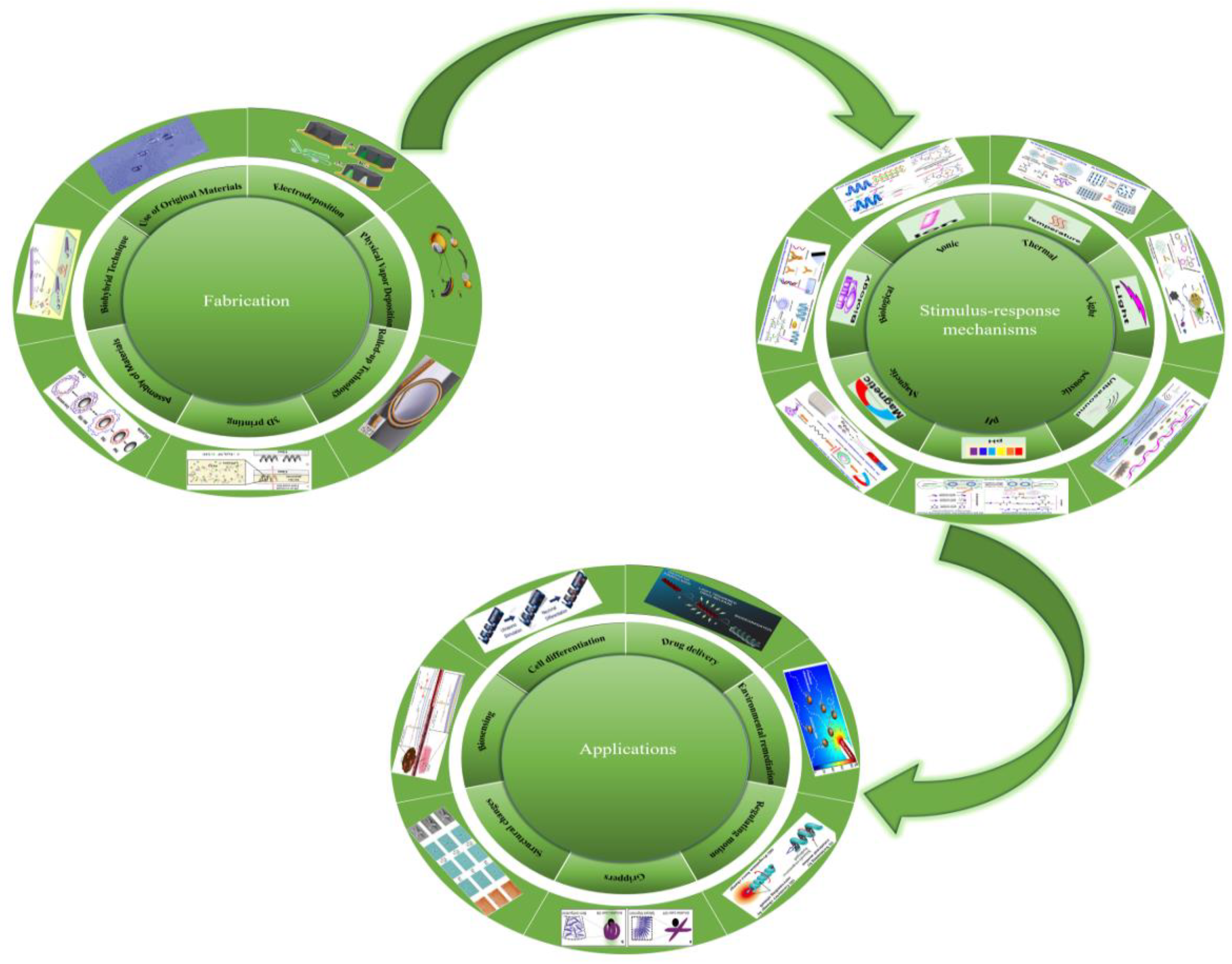
Figure 1. Preparation,stimulus-response mechanisms and applications of micro/nanorobots. Electrodeposition 77. Reproduced from ref 77. Copyright 2011 American Chemical Society. physical vapor deposition 128. Reproduced from ref 128. Copyright 2013 American Chemical Society. Rolled-up Technology 97. Reproduced from refs 97. Copyright 2009 Wiley-VCH.3D printing technology 3. Reproduced from ref 3. Copyright 2020 Wiley-VCH. Assembly of materials 153. Reproduced from ref 153. Copyright 2012 American Chemical Society. Biohybrid Technique 167. Reproduced from ref 167. Copyright 2012 American Chemical Society. Use of Original Materials 172. Reproduced from ref 172. Copyright 2010 Wiley-VCH. Stimuli-responsive mechanisms 1. Reproduced from ref 1. Copyright 2023 American Chemical Society. Drug delivery 20.Reproduced from ref 20. Copyright 2018 American Chemical Society. Environmental remediation 69. Reproduced from ref 69. Copyright 2021 The Authors. Regulating motion 182. Reproduced from ref 182. Copyright 2020 The Authors.Grippers 18. Light stimulus-responsive microrobot for load capture.Reproduced from ref 18. Copyright 2017 WILEY-VCH. Structural changes 184. Reproduced from ref 184. Copyright 2019 WILEY-VCH. Biosensing 67. Reproduced from ref 67. Copyright 2019 WILEY-VCH.Cell differentiation 7. Reproduced from ref 7. Copyright 2019 The Royal Society of Chemistry.
Preprints 91049 g001
Figure 2. modes of electrodeposited nanowires. (A)Membrane template-assisted electrodeposition of nanowires: (a) deposition of gold or silver backing on the membrane template, (b) electrodeposion of sacrificial layer, (c) sequential electrodeposition of desired components, and (d) removal of the backing and sacrificial layer;dissolution of the membrane. Reproduced from refs 70. Copyright 2015 American Chemical Society. (B,C)Schematic representations of the self-electrophoresis mechanism of Ag-Au/Pt and Au/Pt-CNT nanowire motors in H2O2, respectively.Reproduced from refs 81 and 82. Copyright 2008 Wiley-VCH and 2008 American Chemical Society, respectively. (D) Rotation of nanowires by alternating current voltages applied to multiple electrodes: (a) schematic representation of experimental setup of quadruple electrodes and (b) images of free (right) and one end fixed (left) rotating Au nanowires. Reproduced from ref 73. Copyright 2005 American Physical Society. (E) Ultrasound-propelled nanowires: (a−c) illustration of the kinds of motion (chain assembly and axial spinning, axial directional motion and in-plane rotation, and pattern formation) of metal nanowires in an acoustic field; (d) and (e) dark field images of typical chain structures and ring patterns formed by Au and AuRu rods. Reproduced from ref 85. Copyright 2012 American Chemical Society. (F) Preparation procedure of flexible metallic nanowires with polyelectrolyte hinges after membrane template electrodeposition. Reproduced from refs 90. Copyright 2007 Nature Publishing Group. (G) SEM image of a Au/Agflex/Ni nanomotor with flexible central silver segment. Reproduced from ref 74. Copyright 2010 American Chemical Society.
Preprints 91049 g002
Figure 3. modes of electrodeposited microtubes and helical micromotors. (A) Polycarbonate membrane-assisted preparation of conical PANI/Pt microtubes. Reproduced from ref 77. Copyright 2011 American Chemical Society. (B) Anodized aluminum oxide (AAO) membrane-assisted preparation of segmented microtubes. Reproduced from ref 75. Copyright 2013 Royal Society of Chemistry. (C) AAO membrane-assisted preparation of helical micromotors. Reproduced from ref 102. Copyright 2014 Royal Society of Chemistry. (D) Silver wire template-assisted layering approach for preparation of microtubes. Reproduced from ref 103. Copyright 2010 American Chemical Society. (E) Preparation of magnetic helical structure using lipids. Reproduced from ref 104. Copyright 2012 Wiley-VCH. (F) SEM image of nickel-modified carbon nanotube prepared by bipolar electrodeposition. Reproduced from ref 106. Copyright 2010 Elsevier Ltd.
Preprints 91049 g003
Figure 4. Micro/nanomotors prepared by conventional physical vapor deposition. (A) Plant-based helical micromotors prepared through physical vapor deposition. Reproduced from ref 107. Copyright 2013 American Chemical Society. (B)SEM image illustrating an array of self-assembled spherical particles. The inset shows the coating of the Janus particles with metal film providing their catalytic and magnetic properties. Reproduced from ref 46. Copyright 2012 American Chemical Society. (C)Schematic of fabrication of bimetallic Janus micromotors by conventional physical vapor deposition. Reproduced from ref 114. Copyright 2010 American Chemical Society. (D)Formation of sphere dimers via thermal annealing. Reproduced from ref 115. Copyright 2009 Wiley-VCH. (E) Schematic diagram of Mg-based seawater-driven Janus micromotor. Reproduced from ref 56. Copyright 2013 Royal Society of Chemistry. (F) Schematic diagram of GLAD technique and SEM image of the helices prepared by this method. Reproduced from ref 124. Copyright 2013 American Chemical Society. (G) Preparation of asymmetric Pt/Au-coated catalytic micromotors by GLAD. Reproduced from ref 125. Copyright 2010 American Institute of Physics. (H) Fabrication procedure of L-shaped Si/Pt nanorod motors by GLAD. Reproduced from ref 126. Copyright 2007 American Chemical Society. (I) Synthesis of catalytic micromotor consisting of a spherical silica colloid with a TiO2 arm coated asymmetrically with Pt. Reproduced from ref 127. Copyright 2009 Wiley-VCH. (J) Pt−Ag−Au shell micromotor fabricated by GLAD. Reproduced from ref 128. Copyright 2013 American Chemical Society.
Preprints 91049 g004
Figure 5. Micro/nanomotors prepared by Rolled-up Technology. (A) schematic diagram of a rolled-up microtube consisting of Pt/Au/Fe/Ti multilayers on a photoresist sacrificial layer and an array of rolled-up microtubes. Reproduced from refs 97. Copyright 2009 Wiley-VCH. (B) Rolled-up microtubes with graphene oxide as an external layer. Reproduced from ref 131. Copyright 2012 American Chemical Society. (C) Fabrication procedure of helical micromotors using self-scrolling technique. (g) SEM image of a self-scrolled helical structure. Reproduced from ref 135. Copyright 2009 American Institute of Physics. (D) Schematic illustration of the electroosmotic propulsion mechanism and experimental setup of helical micromotors. The propulsion direction of helical micromotors can be controlled by the configuration of the two electrodes between which a direct current bias is applied. Reproduced from ref 137. Copyright 2011 Thomson Reuters.
Preprints 91049 g005
Figure 6. Micromotors fabricated by 3D direct laser writing. (A) Preparation of microswimmers with double helical structures using 3D printing of natural derivatives of chitosan. Reproduced from ref 20. Copyright 2018 American Chemical Society. (B) Changes in the motor behavior of acoustically driven microswimmers before and after the application of a magnetic field.Reproduced from ref 8. Copyright 2018 American Association for the Advancement of Science. (C) (a) Micro-swimmers with optimal 3D double-helix structures are prepared using two-photon polymerization by maintaining arrays of nanoparticles with a continuous magnetic field during fabrication. (b) The spiral micro-swimmer reaches the target location under the action of a rotating magnetic field and subsequently expands and releases the drug under the stimulating action of lysosomal enzymes. Reproduced from ref 29. Copyright 2022 American Chemical Society. (D) (a) Preparation of PDM using 3D printing technology. (b) In the presence of ultrasound, PDM releases drugs in different patterns. Reproduced from ref 3. Copyright 2020 Wiley-VCH. (E) Effect of pH change on microsphere diameter. Reproduced from ref 147. Copyright 2019 Elsevier Ltd. (F) Completion of 3D-3D (car-humanoid robot) shape transformation by microstructures in an acidic environment. Reproduced from ref 150. Copyright 2020 American Association for the Advancement of Science.
Preprints 91049 g006
Figure 7. Fabrication of micromotors by assembly of materials. (A) Preparation of TDMs, exercise, and the process of drug release under alkaline stimulation.Reproduced from ref 63. Copyright 2020 Elsevier Ltd. (B) Combination of microfluidic synthesis, polyelectrolyte complexation and surface-coated magnetic nanomaterials for the preparation of magnetic microrobots with multilayered capsule helical structures. Reproduced from ref 57. Copyright 2021 The Royal Society of Chemistry. (C) Fabrication of (PSS/PAH)5 hollow capsules through LbL assembly.Reproduced from ref 153. Copyright 2012 American Chemical Society. (D) Synthetic procedure of a nanoparticle-based PSC nanomotor.Reproduced from ref 154. Copyright 2013 American Chemical Society. (E)Potted micromotors obtained by self-assembly of hydrophobic MnFe2O4@OANPs in volatile oil droplets by growing bubble templates. Reproduced from ref 12. Copyright 2015 Wiley-VCH. (F) Schematic of magnetically guided, ultrasound-propelled red blood cell micromotors in whole blood. Reproduced from ref 155. Copyright 2014 American Chemical Society. (G) Schematic illustration of a chain of magnetic particles linked by DNA. Reproduced from ref 156. Copyright 2005 Nature Publishing Group. (H) (a)Oxygen bubbles generated by the degradation of hydrogen peroxide fuel by a micro-motor composed of PEDOT/MnO2 oscillate under the effect of ultrasound, which pushes the micro-motor to move. (b) Bubble oscillations in the ultrasound field cause individual micro-motors to aggregate, forming dandelion-like micro-clusters. Reproduced from ref 6. Copyright 2020 Wiley-VCH. (I) Photoresponsive surface based on switchable fluorinated molecular shuttles to expose or conceal fluoroalkane region (orange). Reproduced from ref 162. Copyright 2005 Nature Publishing Group.
Preprints 91049 g007
Figure 8. Fabrication of micromotors by Biohybrid Technique and Use of Original Materials. (A) (a) Preparation process of TDA. (b) EpCAM induces conformational changes in TDA to recognize cancer cells.Reproduced from ref 34. Copyright 2021 The Royal Society of Chemistry. (B)Use of biocatalytic microjets with enzyme immobilized at the inner gold surface as microfish for testing water quality. Reproduced from ref 167. Copyright 2012 American Chemical Society. (C)Prepation of neutrobot. Reproduced from ref 32. Copyright 2021 American Association for the Advancement of Science. (D) Preparation of an AI microrobot with paramagnetic/conducting capability. Reproduced from ref 25. Copyright 2020 Wiley-VCH. (E) Integration of magnetic nanoparticles and nanoliposomes loaded with photothermite and chemotherapeutic molecules onto Escherichia coli for biohybrid microbots. Reproduced from ref 171. Copyright 2022 American Association for the Advancement of Science. (F) Preparation and movement of alg-mag-cells and the cell culture process. Reproduced from ref 15. Copyright 2016 Wiley-VCH. (G) Movement of a TiO2 particle in a suspension of SiO2 particles under UV. Reproduced from ref 172. Copyright 2010 Wiley-VCH. (H)AgCl particles in deionized water (a) before UV illumination, (b) after 30 s, and (c) after 90 s of UV exposure. Reproduced from ref 173. Copyright 2009 Wiley-VCH. (I)Scheme illustrating principle of dynamic bipolar self-regeneration. Reproduced from ref 175. Copyright 2010 American Chemical Society.
Preprints 91049 g008
Figure 9. Examples of thermal stimuli-responsive microrobots. (A)Thermal stimulus response mechanisms in microbots. (a) temperature-induced swelling/contraction of hydrogels. (b)temperature-induced disorder/bending of LCEs. Reproduced from ref 1. Copyright 2023 American Chemical Society. (B,C) Thermosensitive hydrogel microrobot for regulating motion. Reproduced from ref 180 and 182. Copyright 2016 The Authors and 2020 The Authors. (D,E) Magnetically driven thermosensitive hydrogel microrobots for cancer therapy. Reproduced from ref 60 and 61. Copyright 2011Koninklijke Brill NV, Leiden and The Robotics Society of Japan and 2014 American Chemical Society. (F) Thermally Responsive 4D Liquid Crystal Microactuator for Color Sensing. Reproduced from ref 81. Copyright 2021 The Authors.
Preprints 91049 g009
Figure 10. Examples of light stimuli-responsive microrobots. (A)light stimulus response mechanisms in microbots. (a)light-induced bond-cleavage. (b) Light-induced oxidation/reduction reactions. Reproduced from ref 1. Copyright 2023 American Chemical Society. (B) Light stimulus-responsive microrobot for Drug delivery. (a)UV-sensitive microrobot for drug delivery. Reproduced from ref 20. Copyright 2018 American Chemical Society. (b)Hydrogel-based microrobot for near-infrared light-induced drug release.Reproduced from ref 27. Copyright 2019 2020 Elsevier B.V. (C) Light stimulus-responsive microrobots for grippers or microwalkers. (a) Light stimulus-responsive microrobot for load capture. Reproduced from ref 18. Copyright 2017 WILEY-VCH. (b) Light stimulation-responsive microrobot for making a micro-walker. Reproduced from ref 16. Copyright 2015 The Authors. (D) Light stimulus-responsive microrobot for environmental remediation (a) Biohybrid microrobot composed of Fe4O3@TiO2 for removal of organic pollutants from water. Reproduced from ref 19. Copyright 2019 The Royal Society of Chemistry. (b)Metal-free micromotor composed of C3N4 for the removal of heavy metals from water. Reproduced from ref 28. Copyright 2018 American Chemical Society.
Preprints 91049 g010
Figure 11. Examples of Acoustic stimuli-responsive microrobots. (A)Acoustic stimulus response mechanisms in microbots. (a)US-induced cavitation effect. (b)US-induced streaming effect.Reproduced from ref 1. Copyright 2023 American Chemical Society. (B)Acoustic stimulus-responsive microrobot for Reversible swarming and classification. (a)Reversible clustering and dispersion of uitrasound-triggered Pt-Au nanowire motors. (b)Ultrasound-triggered separation of different types of catalytic nanomotors. Reproduced from ref 7. Copyright 2015 American Chemical Society. (C)Ultrasound-sensitive microrobot for neuron-like cell delivery and neuronal differentiation. Reproduced from ref 7. Copyright 2019 The Royal Society of Chemistry. (D)Acoustic stimulus-responsive microrobot for Drug delivery. (a)Ultrasound-sensitive microrobot for alleviating drug resistance due to lactic acidosis induced by tumor tissue. Reproduced from ref 2. Copyright 2020 The Royal Society of Chemistry. (b)Acoustic-magnetic combination allows micro-robots to rapidly release drugs in a short cycle time. Reproduced from ref 4. Copyright 2020 Elsevier B.V.
Preprints 91049 g011
Figure 12. Examples of pH stimuli-responsive microrobots. (A) pH stimulus response mechanisms in microbots. (a) pH-induced bond-hydrolysis. (b) pH regulated intermolecular forces. Reproduced from ref 1. Copyright 2023 American Chemical Society. (B) Oxygen bubbles propel nanorobots to deeply penetrate tumor tissue and release anticancer drugs in the presence of pH. Reproduced from ref 183. Copyright 2020 The Authors. (C) pH change induces structural changes in microbots. Reproduced from ref 184. Copyright 2019 WILEY-VCH. (D)ATP-sensing microbots in acidic tumors. Reproduced from ref 67. Copyright 2019 WILEY-VCH. (E) Removal of estrogenic contaminants from water using pH-sensitive microrobots. Reproduced from ref 62. Copyright 2020 The Authors.
Preprints 91049 g012
Figure 13. Examples of magnetic stimuli-responsive microrobots. (A)magnetic stimulus response mechanisms in microbots. (a)magnetic field modulating the locomotion/shape. (b)magnetic field transferred into electric signals. Reproduced from ref 1. Copyright 2023 American Chemical Society. (B)Magnetic stimulus-responsive microrobot for biomedical. (a)Magnetic stimulation-responsive microrobots for cell differentiation.Reproduced from ref 9.Copyright 2020 WILEY-VCH. (b)Magnetic stimulation-responsive microrobots for tumor therapy. Reproduced from ref 14. Copyright 2021 American Chemical Society. (C)Using magnetic fields to tune the motion behavior of a microrobot.Reproduced from ref 11. Copyright 2018 American Chemical Society. (D)Magnetic stimulus-responsive microrobot for Environmental remediation. (a)Removes oil droplets from water with a jug-shaped micromotor. Reproduced from ref 12. Copyright 2015 Wiley-VCH. (b)Microrobot with core-shell structure degrade organic pollutants in water in the presence of a magnetic field.Reproduced from ref 13. Copyright 2019 WILEY-VCH. (E) Magnetically responsive origami microbots with structural deformation capability. Reproduced from ref 10. Copyright 2020 Proceedings of the National Academy of Sciences.
Preprints 91049 g013
Figure 14. Examples of biological stimuli-responsive microrobots. (A) biological stimulus-response mechanisms in microbots. (a)enzyme-induced bond breaking. (b)biomarker-induced morphology changes. Reproduced from ref 1. Copyright 2023 American Chemical Society. (B)GeIMA-based microrobots for supporting cell adhesion and growth. Reproduced from ref 31. Copyright 2018 WILEY-VCH. (C)Enzyme-responsive molecules for drug delivery. Reproduced from ref 35. Copyright 2021 American Chemical Society.
Preprints 91049 g014
Figure 15. Examples of Ionic stimuli-responsive microrobots. (A) Ionic stimulus-response mec-hanisms in microbots.(a)ion-induced phase changes. (b)ion-induced chelation. Reproduced from ref 1. Copyright 2023 American Chemical Society. (B)Ion exchange micro-robots for drug delivery. Reproduced from ref 57. Copyright 2021 The Royal Society of Chemistry. (C)Ion-triggered microbots for monitoring lead ions in water.Reproduced from ref 68. Copyright 2013 American Chemical Society. (D)Zinc oxide-based micro-motor for detecting carbon dioxide in water. Reproduced from ref 69. Copyright 2021 The Authors.
Preprints 91049 g015
Figure 16. Examples of Multi-stimulus response microrobots. (A)Multi-stimulus-responsive microrobot for drug delivery. (a)(Pd@Au)/Fe3O4@Spirulina microrobots release drugs triggered by near-infrared light/acidic pH. Reproduced from ref 170. Copyright 2019 American Chemical Society. (b)Bacterial biohybrid microrobots deliver drugs triggered by magnetic field/near-infrared light. Reproduced from ref 171. Copyright 2022 The Authors. (c)Magnetically driven, pH/Ca2+ responsive microrobot for drug delivery. Reproduced from ref 188. Copyright 2021 The Authors. (B)Multi-stimulus response microrobot for load capture. (a)Intelligent microbots capture loads in response to multiple stimuli such as humidity, temperature and light. Reproduced from ref 189. Copyright 2019 The Authors. (b)NIPAAm/AAm/PEGDA/Carbon nanoparticle hybrid microrobots capture loads in response to light and temperature stimulation. Reproduced from ref 190. Copyright 2019 The Authors.
Preprints 91049 g016
Table 1. Summary of Fabrication Techniques of Micro/Nanomotors.
Preparation method Type of propulsion Types Propulsion mechanism Ref
electrodeposition membrane template- assisted
Electrode-position
chemical nanowires self-electrophoresis [71,79]
chemical nanotubes bubble recoil [75,77]
magnetic helical magnetic forces/torques [104,107]
magnetic flexible nanowires magnetic forces/torques [74,78,90]
ultrasound nanowires acoustic pressure difffference [85]
electric metallic nanowires Dielectrophoretic force [72,73]
electric metallic microobjects dynamic bipolar self-regeneration [175]
asymmetric bipolar electrodeposition chemical Janus bubble recoil [105]
physical vapor deposition Physical Vapor Deposition chemical Janus self-diffffusiophoresis,self-electrophoresis,
Bubble Propulsion,
Surface tension gradients
[38,46,50,114]
magnetic Janus magnetically induced thermophoresis [108]
light Janus diffffusiophoresis induced by light [113,141]
Glancing angle deposition magnetic helical magnetic forces/torques [120,121]
Rolled-up Technology Rolled-up chemical nanotubes bubble recoil [97]
ultrasound perflfluorocarbon-loaded
microbullets
acoustic droplet vaporization [178]
Self-Scrolling magnetic helical magnetic forces/torques [135]
electric helical electroosmotic flflow [137]
3D direct laser writing magnetic helical magnetic forces/torques [138,139]
light micromotors with anisotropicgeometry optical momentum conversion (OMC) [179]
Assembly of Materials Layer-by-Layer Assembly chemical nanotubes bubble recoil [152]
magnetic chain of magnetic particles magnetic forces/torques [156]
chemical Janus bubble recoil [153]
Assembly and Encapsulation chemical Janus self-diffffusiophoresis [39,154]
ultrasound magnetic nanoparticle-
loaded
red blood cells
asymmetric distribution of encapsulated
magnetic nanoparticles
[155]
light Janus diffffusiophoresis induced by light [157]
Assembly and Incorporation light micromotors based on
photoresponsive surfaces
surface free energy gradient generated by
photoisomerization of molecules
[160,161]
light liquid crystal films/liquid crystal elastomers photoisomerization of molecular motor induced deformation [163,164]
chemical Janus surface tension gradients/bubble recoil [94,159]
BiohybridTechnique Biological Molecules biohybrid micro/nanomotors based on enzymes enzyme-catalyzed reactions [166]
Motile Units biohybrid micro/nanomotors based on motile units intact motile cells [168]
Use of Original Materials light particles of photoresponsive inorganic materials photoinduced self-diffffusiophoresis [172,173]
electric conducting microobjects bipolar chemistry induced asymmetric bubble generation [176]
Table 2. Summary of stimulus response mechanisms and applications of micro/ nanorobots.
Stimuli composition Shape Response Application Ref
temperature NIPAM/AAM/PEGDA/9mTc [Tc] tubular(100 μm diameter ) swelling/shrinking Tracking, imaging [59]
NIPAM/MNPs round swelling/shrinking Treating Cancer [60]
NIPAM/PEDGA/MNPs/Fe3O4 flagellated swelling/shrinking conditioning movement [180]
Mg/Pt-NIPAM spherical(50 um diameter ) swelling/shrinking Drug delivery [61]
LC hexagonal(3 μm height; 20 μm width) swelling/shrinking temperature sensor [181]
NIPAM/AAc/NaAlg spiral(300 μm inner diameter) swelling/shrinking Speed and direction adjustment [182]
light IP-DIP/LCE fourlegged(100 um× 50 um × 10 um) shape transformation Motion Modulation [16]
IP-DIP/LCE four fingers(200 um× 200 um × 20 um) bending deformation Particle Capture [18]
Spirulina platensis/Fe3O4/TiO2 spiral (2.8 μm diameter; 50−80 μm length) photocatalysis degradation Removal of organic contaminants [19]
chitosan double helix
(6μm diameter; 20 μm length)
photocleavage Drug delivery [20]
biotin/NH2−Fe3O4/streptavidin tri-bead(10 μm in length) photocleavage cancer treatment [17]
NIPAM-AAM/PEGDA/SiO2-coatedFe2O3/GO nanosheet tubular(270 μm inner diameter;
580 μm outer diameter)
swelling/shrinking Drug delivery [21]
NIPAM/alginate/MNPs spring(800 μm diameter; 1600 μm length) swelling/shrinking Drug delivery [23]
E-dent 400/PDA/MNPS/lipiodol cylindrical (500 μm diameter) photothermal effect Drug delivery [24]
Geltin/PVA/MNPs/PLGA roun(100−250 μm ) photothermal effect cancer treatment [27]
ultrasound PLGA/PFC Spherical( 150nmdiameter) cavitation effect Drug resistance resulting from the induction of lactic acidosis by tumour tissue. [2]
PEGDA/PETA helix(40 μm diameter; 120 μm length) acoustic streaming effect Effect of various drug release patterns on the therapeutic effectiveness of cancer cells. [3]
E-dent 400/NdFeB helix acoustic streaming effect Reduced stimulus response time for rapid drug release [4]
P(VDF-TrFE)/CFO helix(250 μm inner diameter) acoustic streaming effect Neuron-like cell trafficking and cell differentiation [5]
PEDOT/MnO2 tubular(5 μm diameter; 15 μm length) cavitation effect Dynamic assembly, swarming [6]
Au−Pt tubular(200 nm diameter; 2 μm length) acoustic streaming effect Dynamic assembly, swarming [7]
pH Mg/Au/EUDRAGITU L100- 55 Cy5/Apt/Lip round(20 μm diameter) Consumption of local protons Stomach acid neutralisation, drug release, cancer treatment [58]
chitosan/sodium alginate/Fe3O4 thumbtack-like Dissolved under alkaline conditions Drug delivery [63]
PHEMA/PEGDA/Fe3O4 Eight arms(150 μm thickness) swelling/shrinking, absorption/release of aqueous solutions Drug delivery [64]
IPL-780/PDA/Ni/Ti helix(10 μm helical diameter) pH-induced bond hydrolysis Drug delivery [65]
CoNi/alginate cylindrical swelling/shrinking, absorption/release of aqueous solutions Drug delivery [66]
PPy/Fe3O4/Pt (tubular(12.4 μm length; 4.4 μm width) Charge change-affinity regulation-aggregation of estrogen fibres Removal of estrogenic contaminants from water [62]
Cy5/Apt/Lip coin Acid Driven - Specific Targeting Biosensory imaging (ATP) [67]
AAc/NIPAM/PVP leaf Expansion,contraction, torsion Multi-degree-of-freedom shape transformation [184]
PEGDA/glycerol/CEA pyramid/dome distortion by swelling shape shift [151]
EMK/AAc/NIPAM/DPEPA hollow sphere(60 μm diameter) welling/shrinking shape shift [147]
EMK/AAc/NIPAM/DPEPA humanoid-robot(300 um× 400 um× 400 um) Module Assembly Vehicle-human shape shifting. [150]
magnetic field GelMA/CFO/BFO helix(100 μm length) magnetoelectric effect Inducing neuron-like cell differentiation [9]
NdFeB/silicone origami Magnetic control Instant shape locking while moving without constraints [10]
MnFe2O4/oleic acid pot-like hollow Hydrophobic interactions - tight magnetic shell layer Bubble jet to remove oil droplets [12]
IP-Dip/Ni/Au half-capsule(7.5 μm length; 5 μm diameter;
500 nm thickness)
paramagnetic effect Direction of Motion Adjustment [8]
bio-stimulation enzyme gelatin methacryloyl/
poly(ethylene glycol) amine/Fe3O4
double helical
(20 μm length; 6 μm diameter)
bond hydrolysis-swelling Drug delivery [29]
GelMA/Fe@ZIF-8 helix bond hydrolysis Drug delivery [30]
GelMA/PEGDA/Fe3O4 helix(30 μm length) bond hydrolysis cell culture [31]
inflammatory
factors
gelatin/Fe3O4/neutrophil Neurophil(105 nm diameter) chemotaxis Crossing the blood-brain barrier to release drugs [32]
angiogenic factor VEGF E. coli bacteria spherical specific binding Early Cancer Diagnosis [33]
biomarker (EpCAM) DNA tetrahedral Controlled conformational changes Early Cancer Diagnosis [34]
ion alginate/chitosan/Fe3O4 helical ion exchange Drug delivery [57]
NIPAM/BC18A6m/MNPs spherical chelation sensing Pb2+ ion Heavy metal detection (Pb2+) [68]
ZnO/SiO2 Janus(2.5 μm diameter) Continuous corrosion by H+ Detection of CO2 [69]
Disclaimer/Publisher’s Note: The statements, opinions and data contained in all publications are solely those of the individual author(s) and contributor(s) and not of MDPI and/or the editor(s). MDPI and/or the editor(s) disclaim responsibility for any injury to people or property resulting from any ideas, methods, instructions or products referred to in the content.
Copyright: This open access article is published under a Creative Commons CC BY 4.0 license, which permit the free download, distribution, and reuse, provided that the author and preprint are cited in any reuse.
Prerpints.org logo

Preprints.org is a free preprint server supported by MDPI in Basel, Switzerland.

Subscribe

© 2024 MDPI (Basel, Switzerland) unless otherwise stated