Preprint
Article

Evolution of Tooth Wear Mechanisms during the Bandsawing of Cr12MoV with a Bimetal Bandsaw Blade

Altmetrics

Downloads

93

Views

38

Comments

0

This version is not peer-reviewed

Submitted:

21 November 2023

Posted:

22 November 2023

You are already at the latest version

Alerts
Abstract
Bandsaw blades are typical band-shaped cutting tools characterized by a low stiffness and micro-level cutting depth, resulting in distinct wear mechanisms compared to rigid cutting tools. In this study, the evolution of bandsaw tooth wear mechanisms during the bandsawing of Cr12MoV cold-working steel was investigated. The tool life was divided into two stages according to the tooth wear mechanism: a rapid wear stage (Stage I) and a homogeneous wear stage (Stage II). In Stage I, the wear mechanism was dominated by chipping, although multiple wear mechanisms were found because of the relatively poor manufacturing tolerance compared to rigid cutting tools, resulting in remarkable differences between the cutting depths of the individual teeth. In Stage II, abrasive and adhesive wear were the primary wear mechanisms instead of chipping, due to the decreased width and setting magnitude tolerance after Stage I. Furthermore, methods for increasing the bandsaw performance were proposed based on the tooth wear mechanisms.
Keywords: 
Subject: Engineering  -   Mechanical Engineering

1. Introduction

Since Luban made significant improvements to saws [1], sawing tools, including reciprocating saws, circular saws, chainsaws, wire saws, and bandsaws, have continued to be developed for 2500 years. Due to their small kerf, excellent section quality, and high sawing efficiency, bandsaw blades have been widely used in material cutting-off procedures, especially for workpieces with large sizes [2].
The thickness of the bandsaw blade is between 0.5 mm and 1.6 mm. Thus, the bandsawing vibration is difficult to avoid due to the characteristic band shape with the lack of rigidity, which is distinguished from turning, milling, and various rod tools [3,4,5]. Although several methods have been proposed to limit vibration or chatter during bandsawing, such as roll-tensioning [6,7], stretching [8], surface texture [9] and robust control [10], eliminating vibration is difficult. The characteristics of the bandsaw blade make the wear mechanisms of teeth complicated. Sarwar et al. studied the wear modes of the teeth of bandsaw blades when sawing stainless steel [11], bearing steel [12], and alloy steel [13] and found that flank wear was the main wear mode. Khan et al. [14] found that adhesive wear, frictional wear and diffusion wear were the main wear mechanisms of cutting Ti-17 by a TiAlSiN-coated bandsaw blade, and the TiAlSiN coating effectively improved the life of the bandsaw blade. Zhuo et al. [15] introduced acoustic emission technology to monitor the abnormal wear of bandsaw blade teeth to predict the occurrence of out-of-square phenomenon during bandsawing and reduce the losses of high-value materials. As mentioned above, recent studies on the wear of bandsaw blades have focused on blade wear when the blades are close to failure, and there have been limited studies on the wear mechanisms throughout the whole life cycle of bandsaw blades, especially in the early stage.
Cr12MoV is a cold-work die steel widely used in stamping, die casting moulds, and extrusion dies. In addition, Cr12MoV is a martensitic stainless steel with a C content of 1%, Cr content of 12%, and high work-hardening rate, as well as the presence of high-hardness metal carbides, which is typical for difficult-to-machine materials [16]. Due to the complex and variable shape of the mould, industrial manufacturing requires the large die billet to be split into the required size before subsequent processing. Bandsawing is a common method of slitting mould steel, which is used in large quantities in steel trading enterprises. In this study, we used Cr12MoV steel as the processing workpiece and adopted high-speed photography, electron microscope observation, and other techniques to study the wear mechanism of saw teeth in the early and late stages of the bandsaw blade life cycle and to discuss ways to improve the life of bandsaw blades under these working conditions.

2. Experimental Procedure

2.1. Bandsaw Blade and Workpiece Material

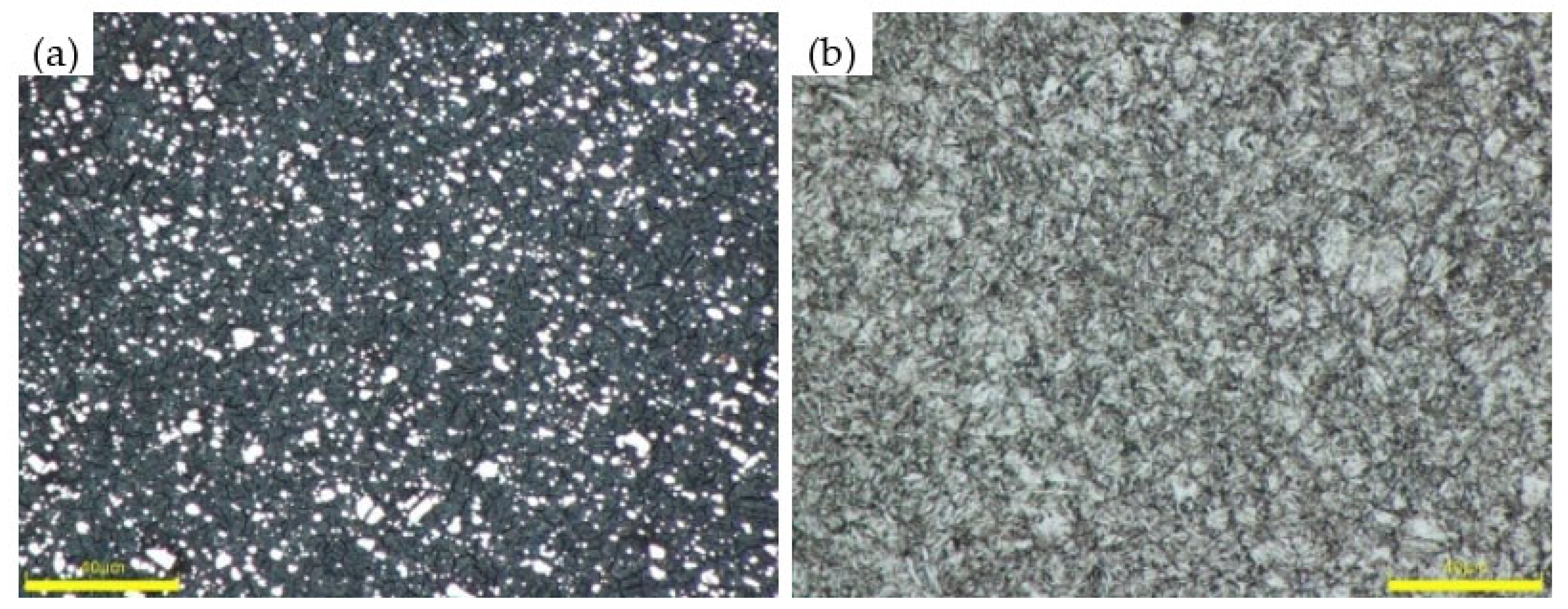
The bimetal bandsaw blade (hereinafter referred to as bandsaw) tested in this study had dimensions of 41 mm × 1.3 mm and 2/3 teeth per inch (TPI), and its basic information is provided in Table 1. The tooth material of the bandsaw was M42 high-speed steel (HSS) with a hardness of 940–980 HV. Figure 1a shows its metallographic structure. The carbide was uniformly distributed in the tempered martensite matrix, and the maximum carbide size was <10 μm. The saw blade body was composed of X32CrMoV4-1 high-strength spring steel with a hardness of 490–530 HV, and its structure was mainly tempered sorbite (as shown in Figure 1b). The nominal compositions of the tooth and body materials are listed in Table 2.
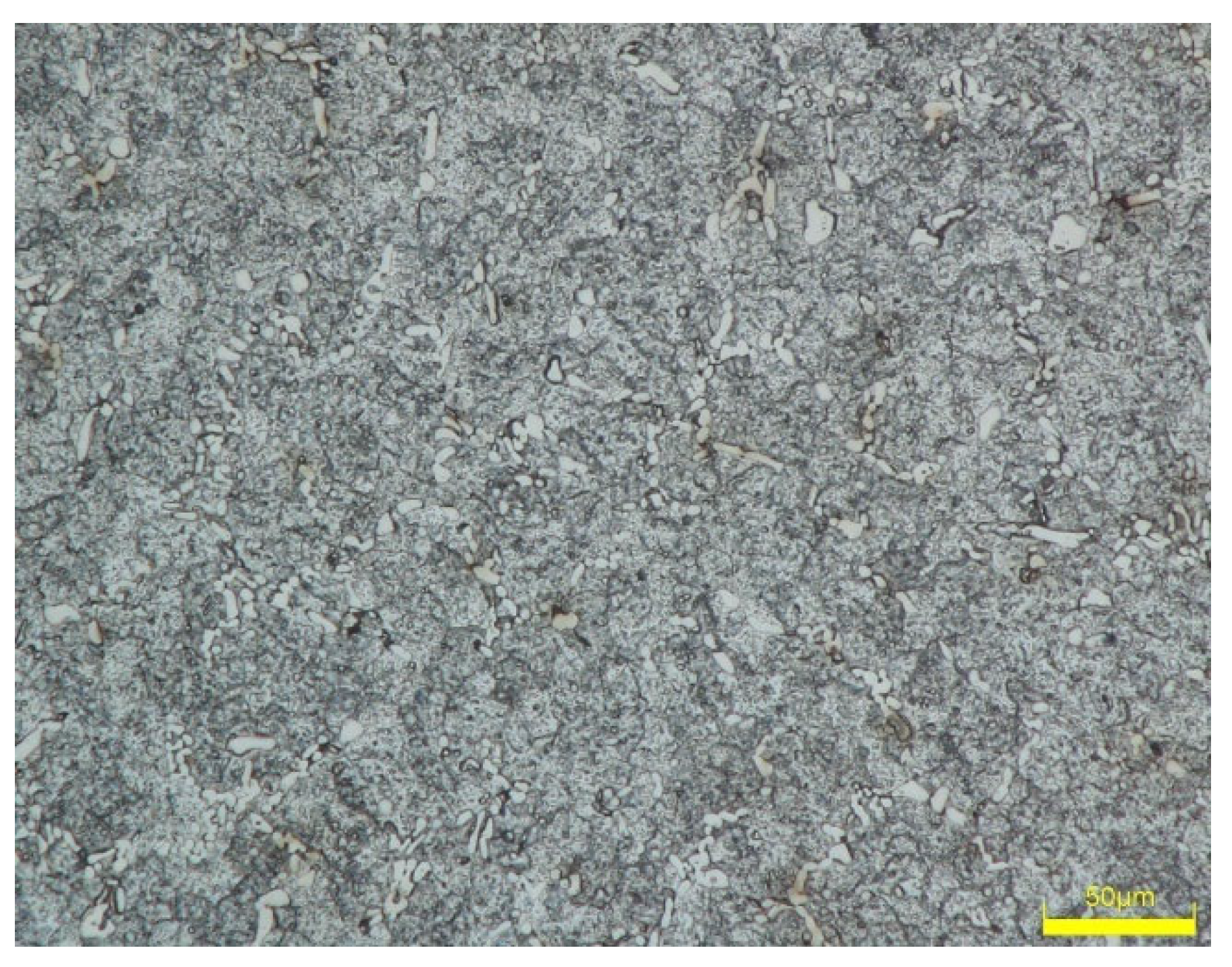
The workpiece material was a Cr12MoV cold-work die steel square with a size of 400 mm × 200 mm and an average hardness of 267 HV. Its metallographic structure is depicted in Figure 2, which shows an annealed structure, and the metal carbides were distributed in a pearlite matrix in the form of dots or strips.
Table 1. Basic information regarding the bandsaw used in the experiment.
Item Content
Section size (width × thickness) 41 mm × 1.3 mm
Pitch (TPI) Variable pitch (2/3 TPI)
Rake angle/clearance angle 10°/30°
Setting sequence Left - right - left - right - neutron
Kerf width 2.1 mm
Tooth material/hardness M42/940–980 HV
Body material/hardness X32CrMoV4-1/490–530 HV

2.2. Experimental Method

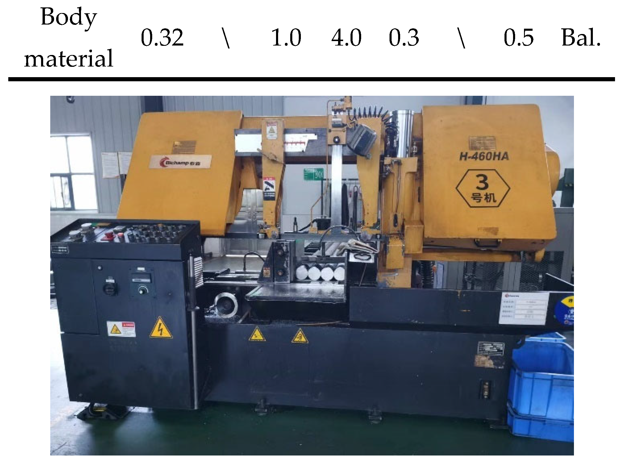
A sawing test was conducted using an H-460HA horizontal bandsaw machine. Figure 3 shows the appearance of the bandsaw machine. The bandsaw did not undergo a break-in procedure, and a band speed of 40 m/min and a feed speed of 10 mm/min were used for the sawing test from the first cut. The average cutting depth per cut was 2.5 μm. A Hispec high-speed camera was used to observe the sawing and cutting forming process of the new saw blade, and the image acquisition rate was 3500 frames/s. The bandsaw was removed after every five cuts, and a VMS-3020H video measuring system was used to detect the flank wear of the saw tooth. Then, the bandsaw was reinstalled on the saw machine to continue the sawing test. This process was repeated until the bandsaw blade failed. When measuring the flank wear, the width of the wear platform at the left, middle, and right sides of each tooth was measured, and the maximum value was considered the wear amount of the tooth [17]. In this test, the phenomenon such as body fractures, tooth breakage, or continued tooth stripping didn’t occur. The failure mode was out-of-square, in which the vertical error of the workpiece was too large due to severe tooth wear (criterion standard: perpendicular error of the workpiece section >1.5% × 200 mm). The material structure was observed by an OLYMPUS DSX510 digital microscope. An FEI Quanta200 scanning electron microscope (SEM) was used to observe the tooth morphology after failure in the secondary electron mode.
Table 2. Chemical compositions of the tooth and body materials (mass fraction, %).
C W Mo Cr V Co Ni Fe
Tooth material 1.08 1.5 9.4 3.8 1.2 8.0 \ Bal.
Body material 0.32 \ 1.0 4.0 0.3 \ 0.5 Bal.

3. Results and Discussion

3.1. Wear Curve of the Saw Tooth

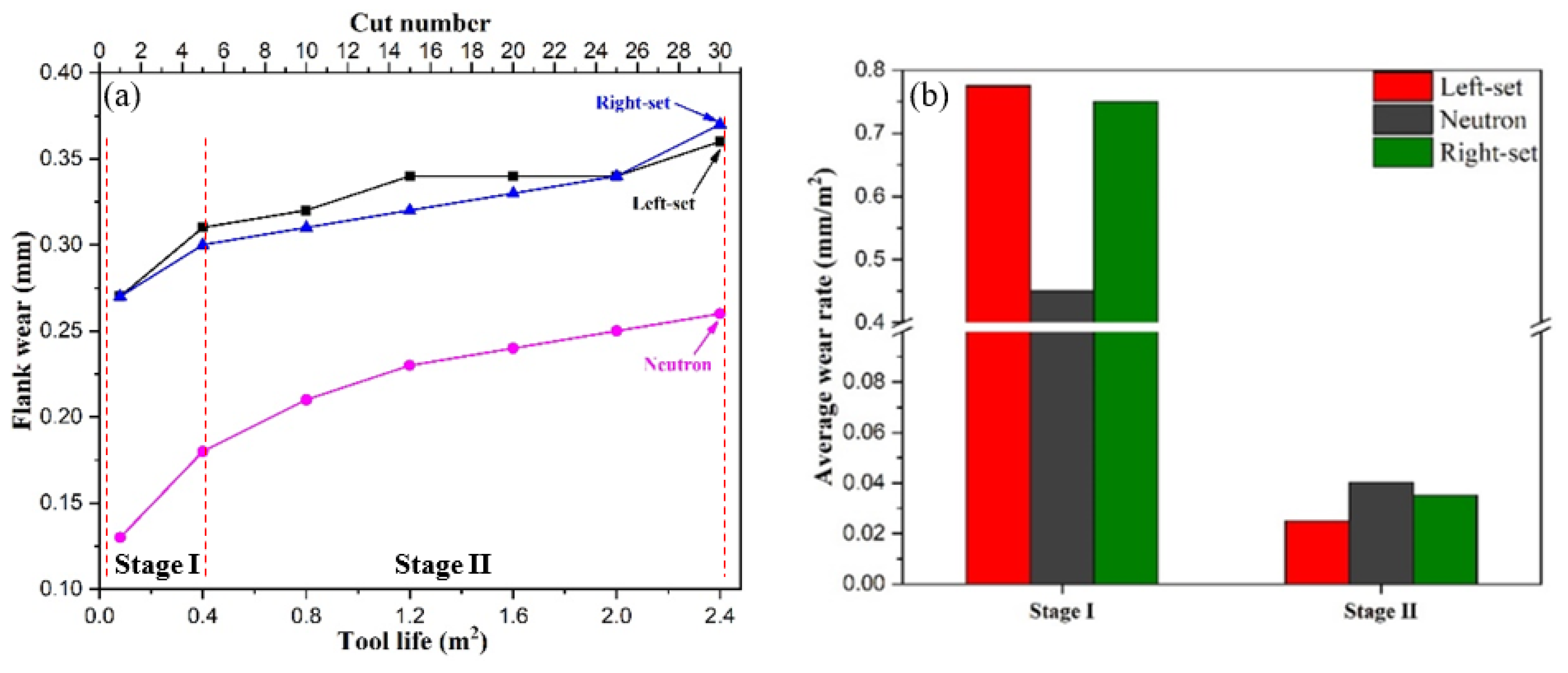
Starting from sawing 0.08 m2 (sawing the first cut), the bandsaw was removed after every five cuts for flank wear measurement. The wears of the neutron, left-set, and right-set teeth were measured, and the flank wear evolution is shown in Figure 4a. The bandsaw employed in the sawing test finally failed after sawing 2.4 m2, and the failure mode was that the out-of-square was more than 3 mm, which was due to the large wear of the teeth after sawing 2.4 m2, and the flank wear of the neutron, left-set, and right-set tooth reached 0.26 mm, 0.36 mm, and 0.37 mm, respectively.
As shown in Figure 4a, the flank wear of the neutron tooth was less than that of the set tooth due to the shape characteristics of different teeth. The wear of both the neutron and set teeth was characterized by two stages: Stage I - sawn area below 0.4 m2, and Stage II - sawn area over 0.4 m2. When the sawn area reaches 0.4 m2, the flank wears of the neutron, left-set, and right-set tooth were 0.18 mm, 0.31 mm, and 0.30 mm, respectively, which is 69.2%, 86.1%, and 81.1% of those of the failed bandsaw, while the tool life percentage at this time is only 16.7% (= 0.4/2.4 × 100%). After the sawing area exceeded 0.4 m2, the tooth wear entered Stage II, when the wear rate decreased significantly. The average wear rates of the neutron, left-set, and right-set teeth at this stage were 0.04 mm/m2, 0.025 mm/m2, and 0.035 mm/m2, respectively (as shown in Figure 4b).
Common tool wear curves are characterized by three stages: rapid wear in the first stage, uniform wear in the second stage, and severe wear in the later stages [18,19]. However, in this study, the bandsaw teeth did not exhibit severe wear in Stage III because bandsaw blades, which are flexible cutting tools, fail mainly because of out-of-square or body fracture. When teeth are severely worn, the feed force will increase, forcing saw blade body bending. When the bending reaches a critical value, out-of-square wear will occur. At this time, the tooth wear has not entered Stage III (severe wear stage). If out-of-square wear does not occur, the saw teeth will be violently worn (the third stage of wear), and the so-called “domino stripping of teeth” phenomenon will occur, which did not appear in this study.

3.2. Saw Tooth Wear Mechanism in Stage I

To explore the mechanism of tooth wear in Stage I, the bandsaw was removed after one cut for morphological observation. A total of 200 teeth were randomly selected from the entire bandsaw for observation, and significant differences were found in the wear modes of the different teeth. For the purpose of discussion, the wear modes of teeth at this stage were divided into four types.
The first type is mild wear without chipping, as shown in Figure 5a. It is characterized by a small amount of saw tooth wear (usually flank wear below 0.1 mm), while no wear is found on a few saw teeth, indicating that they are not cut with the workpiece. The saw teeth were relatively intact without chipping. Eleven of the 200 teeth were found to be worn with such characteristics, accounting for 5.5%.
The second type is significant wear without chipping, as shown in Figure 5b. Compared with the first type, the wear of this type is larger, usually over 0.1 mm, and a built-up edge (BUE) can be observed on several teeth. However, the integrity of the teeth is good, and no chipping is seen. A total of 64 teeth with these characteristics were identified, accounting for 32% of the total.
The third type is chipping, as indicated by the red arrow in Figure 5c. In this type of wear, teeth were observed to be chipped. The chipping positions of some teeth were in the middle, and those of other teeth were on the corners. However, the common feature was that the chipping width was no larger than 1/2 of the width of the tooth, usually being between 1/5 and 1/3. This type of wear accounted for the largest proportion of the saw teeth (107 saw teeth, or 53.5% of the total).
The fourth type is tooth breakage, such as the position indicated by the red arrow in Figure 5d. This wear type of saw tooth is seriously damaged. Both sides of the corner have large breakage, the size of the gap accounts for more than 1/2 of the width of the saw tooth, and in extreme cases, a completely broken saw tooth can be seen. A total of 18 serrations with such wear characteristics were found, accounting for 9%.
The phenomenon that different saw teeth of a bandsaw are worn in different modes is probably due to the different cutting depths, resulting in the different cutting forces of different teeth. When a saw tooth is subjected to a large force, the third and fourth wear types are inclined to occur, and when a saw tooth is subjected to a small force, the first and second wear types are more likely to occur. To verify the assumption above, high-speed photography was used to obtain a real-time picture for in situ observation during bandsawing by a new saw blade, as shown in Figure 6. Large differences were found in the cutting depths of different teeth. Some of the teeth had larger cutting depths and formed thicker chips, as shown in Figure 6a. In this case, the cutting force of the teeth was high, causing significant wear or chipping, and in extreme cases, tooth breakage could occur. The cutting depth of some of the teeth was relatively small, and the formed chip was fine and thin, as shown in Figure 6b. In this case, the cutting force was relatively small, the corresponding wear was mild, and the saw teeth were only slightly worn, as shown in Figure 5a. In the high-speed photographic observations, a few teeth were found not to be in contact with the workpiece, as shown in Figure 6c, and thus did not cut the workpiece; consequently, tooth wear did not occur.
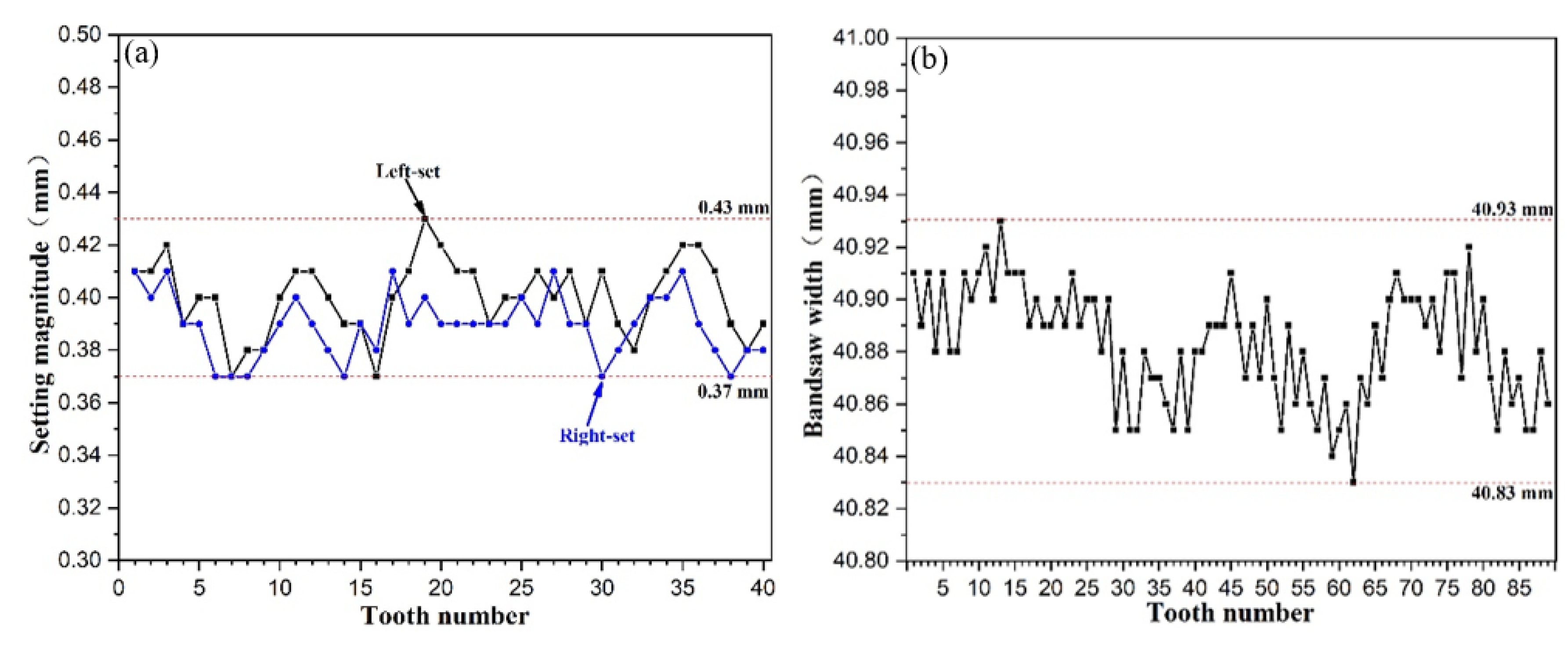
This phenomenon is probably due to the bandsaw processing accuracy. For bimetal bandsaws, the teeth are usually shaped by a milling cutter followed by a setting process to form neutron teeth, left-set teeth, and right-set teeth. In the case of milling, production is stroke by stroke rather than continuous, where the stroke length is determined by the length of the milling cutter [20], and a joint will be formed between two adjacent strokes. The accuracy of the joint will affect the accuracy of the bandsaw. Meanwhile, the milling cutter will also experience wear during use, and as the milling cutter edge becomes worn, the width of the bandsaw during formation processing will change (usually, the width will gradually increase). The milling cutter needs resharpening when worn to a certain extent, and the width before and after resharpening is likely to alter. All these factors will affect the accuracy of the bandsaws. Similarly, tooth setting processing is affected by several factors, such as equipment rigidity, operator experience, and wear of the tooth setting tool. To determine the deviation of the width of the bandsaw (distance from the tooth tips to the bottom edge) and the actual accuracy of tooth setting, the widths of 89 consecutive teeth of the new saw blade, 40 consecutive left-set teeth, and 40 consecutive right-set teeth were measured, as shown in Figure 7. The width of the bandsaw fluctuated from 40.83 mm to 40.93 mm, i.e., within a range of 0.1 mm (as shown in Figure 7a), and the setting magnitude varied from 0.37 mm to 0.43 mm, i.e., within a range of 0.06 mm (as shown in Figure 7b). The average depth of cut per tooth is usually small and is only 2.5 μm (i.e., 0.0025 mm) in this study or only 1/40 of the width fluctuation range and 1/28 of the setting fluctuation range. Fluctuations in the width and setting magnitude are inclined to result in different cutting depths of different teeth. The tooth with a relatively small width and small setting magnitude withstands a small cutting depth, and in contrast, a large cutting depth occurs on the tooth with a relatively large width and small setting magnitude, which is easily chipped or broken.
As a multi-point cutting tool, the cutting depths and forces on different teeth of a new bandsaw should ideally be uniform. However, the actual cutting depths and forces of different teeth vary due to the processing accuracy of the bandsaw. Thus, the saw teeth were worn in different types. For most of the saw teeth, because of the relatively large cutting depth, the cutting resistance was large, so the saw teeth wore quickly, and chipping or breaking tended to occur. Chipping is the main wear type, and it is the main reason for the rapid wear of the bandsaw blade in Stage I. After Stage I (rapid wear), the wear of saw teeth entered Stage II (stable wear) due to the even saw teeth after wear in Stage I.

3.3. Saw Tooth Wear Mechanism in Stage II

When the saw tooth wear enters Stage II, the different saw teeth become even until the bandsaw blade fails. Except for seriously damaged saw teeth in Stage I, most of the remaining saw teeth eventually present uniform wear, as shown in Figure 9. However, because of the specificity of the distribution of the bandsaw blade teeth, different teeth form kerfs at different positions, leading to differences in their wear characteristics. For neutron tth, both sides of tooth are worn more severely than the central part of tooth, forming an arc shape after uniform wear, as shown in Figure 8a. For the set tooth, the major part that withstands wear is the outside of the saw tooth, that is, the left side of the saw tooth for the left-set tooth and the right side of the saw tooth for the right-set tooth. Therefore, the set tooth is mainly unilateral wear, as shown in Figure 8b and Figure 8c, which meets the results of research by Sӧderberg et al. [21].
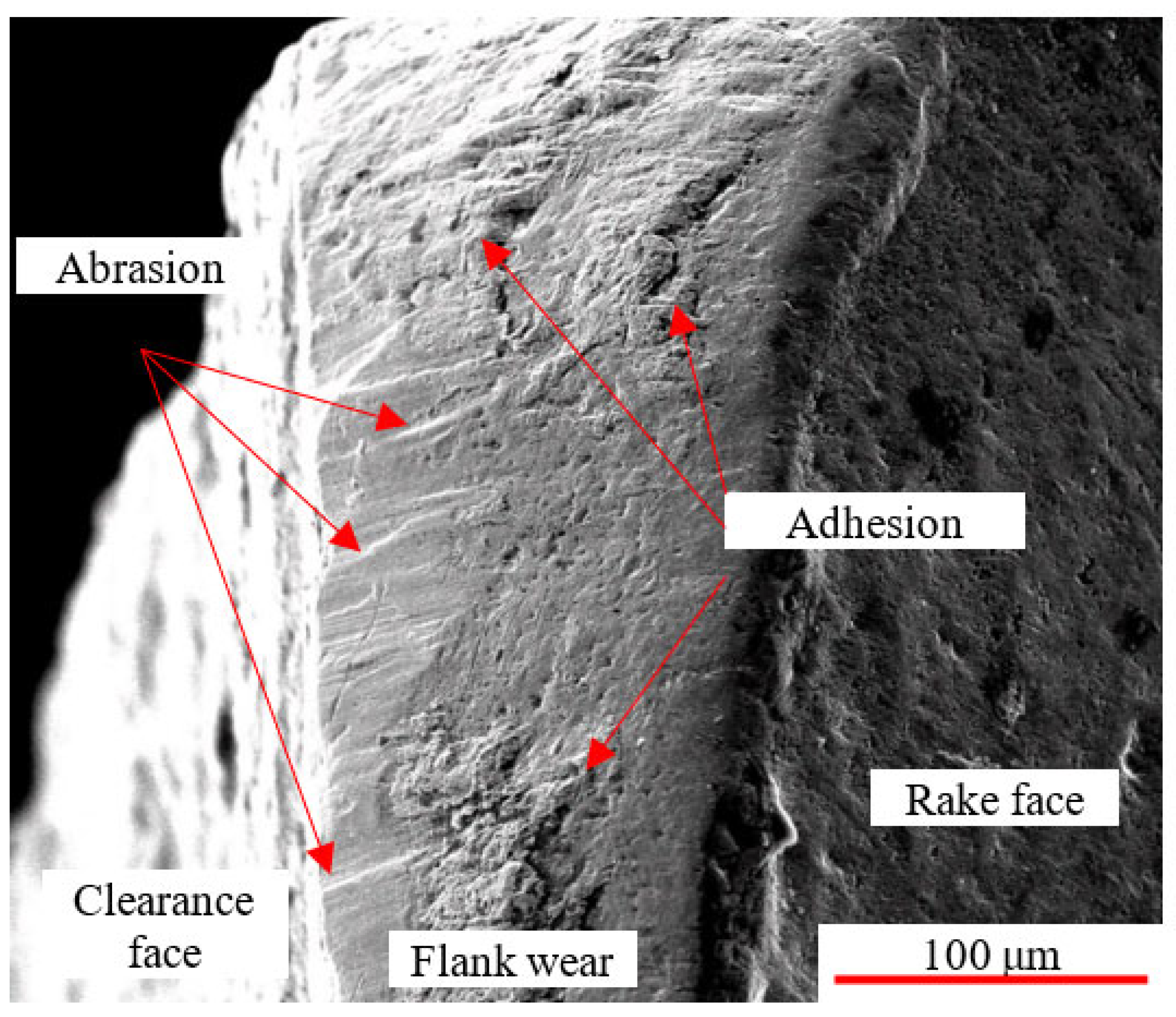
In Stage II, the saw teeth gradually become even, so chipping of the saw teeth infrequently occurs, and the wear of the saw teeth presents a wear mechanism different from that in Stage I. The SEM images of the bandsaw blade teeth after failure are shown in Figure 9, which exhibits two different tooth wear mechanisms in Stage II. Obvious adhered workpieces are observed, and most of them are tightly adhered to the saw teeth. However, some of the large adhered workpieces have cracks between them and the saw teeth, indicating that they are about to peel off. The parts show the characteristics of adhesive wear. Meanwhile, small scratches exist on the worn surface of the saw tooth, and the direction of the scratches is consistent with the cutting direction, which presents abrasive wear. The workpiece material (Cr12MoV cold-work die steel) used in this study is high-C, which is a high-Cr martensitic stainless steel with a C content of approximately 1%. Thus, there are more carbides with high hardness on the matrix. These carbides abrade the saw teeth during bandsawing, so the bandsaw blade teeth develop abrasive wear. In summary, adhesive and abrasive wear are the main wear mechanisms of the bandsaw blade teeth in Stage II.

3.4. Suggestions for Improving the Sawing Performance of Bandsaws

As mentioned above, the wear of bandsaw teeth when sawing Cr12MoV is divided into two stages: Stage I-rapid wear stage, during which the wear mechanism is characterized by chipping being dominant and various forms of wear coexisting; and Stage II-homogeneous wear, during which adhesive and abrasive wear are the main wear mechanisms. Therefore, suppressing chipping in Stage I and adhesive and abrasive wear in Stage II are the main methods for improving the sawing performance of bandsaws.
Edge preparation of saw teeth by sandblasting was previously proposed to reduce the previous chipping of bandsaw teeth [22,23]. Since bandsawing features a small cutting depth of a single tooth (the average cutting depth of a single tooth in this study was 2.5 μm, while the cutting depths of other methods such as turning, drilling, and milling are usually more than 100 μm [24,25,26]), the edge radius of bandsaws should not be too large, which distinguishes it from other cutting tools. The main reason for chipping in Stage I is the large tolerance of the processing accuracy of the bandsaw blade (greater than the cutting depth of a single tooth); thus, improving the processing accuracy of the bandsaw blade is an effective way to reduce chipping. A method to manufacture a bimetal bandsaw blade by CNC grinding instead of milling was proposed to improve the width accuracy of the bimetal bandsaw blade from 0.1 mm (as shown in Figure 6a) to ≤0.05 mm [27]. Break-in procedures are widely used in bandsawing, especially for hard-to-machine materials with a high rate of work hardening, such as stainless steel and superalloys. When executing the break-in procedure, the operator needs to decrease the feed rate to reduce the average cutting depth per tooth and then reduce the cutting force. Then, the feed rate is increased gradually to the normal value after some time. However, there are many factors that will influence the break-in procedure, such as the bandsaw’s quality, stability of the bandsaw machine, and workpiece, and operators generally perform the break-in procedure based on their own experience.
Adhesive and abrasive wear are the main wear mechanisms of Stage II, so improving the wear resistance of the saw teeth is beneficial for reducing the wear during Stage II. The application of powder metallurgy HSS instead of traditional HSS is effective; for example, ASP2042 [28] and ASP2051 [29] are better options for saw tooth materials. PVD technology has been broadly used for various tools, such as lathing tools, milling cutters, drills, and circular saws. Researchers have tried to apply PVD technology to improve the sawing performance of bandsaws, and the life of bandsaws has obviously improved [14]. However, unlike other tools, PVD coating is not widely utilized in bandsaws at present due to its high cost and the special shape of bandsaws.
4. Conclusions

(1) The saw tooth wear mechanism when Cr12MoV is machined by a bimetal bandsaw blade evolves and shows two stages of characteristics: rapid wear stage and uniform wear stage.
(2) The wear mechanisms of the saw teeth in the two stages are different. In Stage I, chipping is the dominant wear mechanism, and multiple mechanisms coexist. These mechanisms are related to the processing accuracy of the bandsaw blade, where deviations in the width and setting magnitude are the main effects. Less chipping occurs, and adhesion and abrasive wear dominate the tooth wear mechanism in Stage II because the teeth are more even after wear.
(3) Reducing the chipping in Stage I and adhesive and abrasive wear in Stage II are conducive to the tool life of the bandsaw. Tooth edge preparation, processing accuracy improvement, and break-in procedures can reduce chipping in Stage I. The use of powder metallurgy high-speed steel as the tooth material and application of PVD technology can suppress adhesion and abrasive wear in Stage II.

Acknowledgments

This research was financially supported by the Hunan High-Tech Industry Scientific and Technological Innovation Leading Program of Hunan Province (Grant No. 2022GK4049) and the Science and Technology Innovation Program of Hunan Province (Grant No. 2022RC1050). Mr. Robert C. Hayden is appreciated for providing consultation.

References

  1. Jones, P. A.; Simons, E. N. The story of the saw. Spear and Jackson Limited 1961.
  2. Wang, Y.; Zhang, Y.; Tan, D.; Zhang, Y. Key Technologies and Development Trends in Advanced Intelligent Sawing Equipments. Chin. J. Mech. Eng. 2021, 34, 30. [Google Scholar] [CrossRef]
  3. Lengoc, L.; McCallion, H. Wide bandsaw blade under cutting conditions: Part I: Vibration of a plate moving in its plane while subjected to tangential edge loading. J. Sound Vib. 1995, 186, 125–142. [Google Scholar] [CrossRef]
  4. Lengoc, L.; McCallion, H. Wide bandsaw blade under cutting conditions: Part II: Stability of a plate moving in its plane while subjected to parametric excitation. J. Sound Vib. 1995, 186, 143–162. [Google Scholar] [CrossRef]
  5. Lengoc, L.; McCallion, H. Wide bandsaw blade under cutting conditions: Part III: Stability of a plate moving in its plane while subjected to non-conservative cutting forces. J. Sound Vib. 1995, 186, 163–179. [Google Scholar] [CrossRef]
  6. Fujiwara, K. Experimental verification of bandsaw roll-tensioning theory. J. Wood Sci. 2002, 48, 359–364. [Google Scholar] [CrossRef]
  7. Fujiwara, K. Theoretical analysis of bandsaw roll-tensioning. J. Wood Sci. 2002, 48, 277–282. [Google Scholar] [CrossRef]
  8. Gendraud, P.; Roux, J. C.; Bergheau, J. M. Vibrations and stresses in band saws: A review of literature for application to the case of aluminium-cutting high-speed band saws. J. Mater. Process. Technol. 2003, 135, 109–116. [Google Scholar] [CrossRef]
  9. Ni, J.; Lang, J.; Wu, C. Effect of surface texture on the transverse vibration for sawing. Int. J. Adv. Manuf. Technol. 2017, 92, 4543–4551. [Google Scholar] [CrossRef]
  10. Christopher, J. D.; Le-Ngoc, L. Robust Active Vibration Control of a Bandsaw Blade. J. Vib. Acoust. 1999, 122, 69–76. [Google Scholar]
  11. Sarwar, M.; Persson, M.; Hellbergh, H. Wear of the cutting edge in the bandsawing operation when cutting austenitic 17-7 stainless steel. Wear 2007, 263, 1438–1441. [Google Scholar] [CrossRef]
  12. Sarwar, M.; Persson, M.; Hellbergh, H. Wear and failure modes in the bandsawing operation when cutting ball-bearing steel. Wear 2005, 259, 1144–1150. [Google Scholar] [CrossRef]
  13. Sarwar, M.; Persson, M.; Hellbergh, H.; Haider, J. Forces, wear modes, and mechanisms in bandsawing steel workpieces. In Proceedings of the Institution of Mechanical Engineers, 2010/11/01., Part B: Journal of Engineering Manufacture.
  14. Khan, F. N.; Daadbin, A.; Persson, M.; Haider, J.; Hellbergh, H. Assessing the performance of TiAlSiN coating on bandsaw tooth when cutting Ti-17 alloy. Proceedings of the Institution of Mechanical Engineers, Part B: Journal of Engineering Manufacture 2012, 226, 870–877. [Google Scholar] [CrossRef]
  15. Zhuo, R.; Deng, Z.; Chen, B.; Liu, G.; Bi, S. Overview on development of acoustic emission monitoring technology in sawing. Int. J. Adv. Manuf. Technol. 2021, 116, 1411–1427. [Google Scholar] [CrossRef]
  16. Li, W.; Zhang, L.; Wu, C.; Cui, Z.; Niu, C. Influence of Tool and Workpiece Properties on the Wear of the Counterparts in Contact Sliding. J. Tribol. 2022, 144, 021702. [Google Scholar] [CrossRef]
  17. Zhuo, R.; Deng, Z.; Chen, B.; Liu, T.; Ge, J.; Liu, G.; Bi, S. Research on online intelligent monitoring system of band saw blade wear status based on multi-feature fusion of acoustic emission signals. Int. J. Adv. Manuf. Technol. 2022, 121, 4533–4548. [Google Scholar] [CrossRef]
  18. Shaw, M. C. Metal Cutting Principles. Oxford University Press, Inc. 2005.
  19. Bhushan, B. Introduction to Tribology. John Wiley & Sons, Ltd 2013.
  20. Sarwar, M.; Haider, J. Aspects of burr formation in bandsaw teeth manufactured by milling operation. Robot. Comput. -Integr. Manuf. 2010, 26, 596–601. [Google Scholar] [CrossRef]
  21. Söderberg, S.; Åhman, L.; Svenzon, M. A metallurgical study of the wear of band-saw blades. Wear 1983, 85, 11–27. [Google Scholar] [CrossRef]
  22. Jia, Y.; Wu, Y.; Ouyang, W.; Liu, G.; Peng, D.; Chen, G. Effects of Shot Peening on Cutting Life and Fatigue Resistance of Bi-metal Bandsaw Blade. Tool Eng. 2017, 51, 37–40. (in Chinese). [Google Scholar]
  23. Fleming, M. G. Investigation of the wear and failure modes of surface engineered multipoint cutting tools. Dublin City University, 1992.
  24. Karmiris-Obratański, P.; Karkalos, N. E.; Kudelski, R.; Markopoulos, A. P. Experimental study on the effect of the cooling method on surface topography and workpiece integrity during trochoidal end milling of Incoloy 800. Tribol. Int. 2022, 176, 107899. [Google Scholar] [CrossRef]
  25. Yu, Z.; Zeng, D.; Hu, S.; Zhou, X.; Lu, W.; Luo, J.; Fan, Y.; Meng, K. The failure patterns and analysis process of drill pipes in oil and gas well: A case study of fracture S135 drill pipe. Eng. Fail. Anal. 2022, 138, 106171. [Google Scholar] [CrossRef]
  26. Shoja, S.; Norgren, S.; Andrén, H. O.; Bäcke, O.; Halvarsson, M. On the influence of varying the crystallographic texture of alumina CVD coatings on cutting performance in steel turning. Int. J. Mach. Tools Manuf. 2022, 176, 103885. [Google Scholar] [CrossRef]
  27. Jia, Y.; Ouyang, W.; Liu, G.; Hayden, R. Method for making bandsaw blade and bandsaw blade. China, 201610738676.X, 2019.
  28. https://www.erasteel.com/products/asp2042-2/.
  29. https://www.erasteel.com/products/asp2051/.
Figure 1. Microstructures of different parts of the bandsaw: (a) tooth (M42 high speed steel); (b) body (X32CrMoV4-1 high strength spring steel).
Preprints 91108 g001
Figure 2. Microstructure of the Cr12MoV workpiece.
Preprints 91108 g002
Figure 3. Bandsawing machine of the experiments.
Preprints 91108 g003
Figure 4. Wear of tooth of bandsaw in tool life: (a) wear curve; (b) average wear rate.
Preprints 91108 g004
Figure 5. Different wear modes in Stage I: (a) mild wear, no chipping; (b) significant wear, no chipping; (c) chipping; (d) tooth breakage.
Preprints 91108 g005
Figure 6. High speed photographs of bandsawing workpiece by new bandsaw: (a) large cutting depth; (b) small cutting depth; (c) tooth not touching workpiece.
Preprints 91108 g006
Figure 7. Variations of dimensions of new bandsaw: (a) width of bandsaw; (b) setting magnitude.
Preprints 91108 g007
Figure 8. Typical worn teeth morphologies of a failed bandsaw: (a) neutron tooth; (b) left-set tooth; (c) right-set tooth.
Preprints 91108 g008
Figure 9. SEM morphologies of the teeth of a failed bandsaw.
Preprints 91108 g009
Disclaimer/Publisher’s Note: The statements, opinions and data contained in all publications are solely those of the individual author(s) and contributor(s) and not of MDPI and/or the editor(s). MDPI and/or the editor(s) disclaim responsibility for any injury to people or property resulting from any ideas, methods, instructions or products referred to in the content.
Copyright: This open access article is published under a Creative Commons CC BY 4.0 license, which permit the free download, distribution, and reuse, provided that the author and preprint are cited in any reuse.
Prerpints.org logo

Preprints.org is a free preprint server supported by MDPI in Basel, Switzerland.

Subscribe

© 2024 MDPI (Basel, Switzerland) unless otherwise stated