1. Introduction
The need to monitor such emergencies as fires and floods in real time for the large territory of Kazakhstan requires the use of remote sensing satellites in high orbits. In this paper, to cover the largest possible area and provide high temporal and spatial resolution, it is proposed to use a satellite formation flying at GEO and representing a synthetic aperture telescope in the form of a Fizeau interferometer that provides a high spatial resolution corresponding to the resolution of an individual telescope with a high quality optical system [
1]. The use of multi-aperture telescope makes it possible to obtain a high quality image of the Earth's surface with the help of 3 and more satellites representing its optical elements [
2,
3,
4,
5,
6,
7,
8].
The considered in this paper satellite formation flying forms a telescope operating in infrared range and consisting of three mirror satellites located in one plain and imaging satellite located above this plane on the distance equal to the focal length of telescope. In other words, satellite formation flying have the form of tetrahedron or regular pyramid. High-resolution monitoring requires to keep the geometrical configuration of formation with high accuracy [
9].
Several authors study the problem of developing control for the satellite formation flying representing the multi-aperture telescope. In [
10] the result of control for satellite formation as three satellite interferometer is obtained. The formation is kept rigid with position error tolerance 0.2 m. Developed adaptive controller provides tracking the desired trajectories for every satellite in formation taking into account actuator saturation constraints.
In [
11] the role of relative dynamics models for formation flying control system analysis was established, and the need for simple and high-fidelity dynamics models was identified. Authors considered the problem of keeping the satellite formation flying for a DARWIN-type mission in LEO and near L2 point. At first the relative dynamics models for formation flying were established taking into account appropriate perturbations. Further LQR controller was represented for formation keeping with the accuracy of 0.2 - 0.4 m.
In [
12] the problem of control of satellite formation for the mission of synthetic aperture telescope at GEO is considered. The precise relative motion dynamic model of satellite formation flying is represented using Relative Orbital Elements (ROEs) with account of J22 effect. Control system is developed based on LQR technique and provided the relative position accuracy 0.15-0.2m.
Thus, to provide the operation of a synthetic aperture telescope it is necessary to have a control system that would ensure the conservation of the satellite formation configuration taking into account perturbations typical for GEO, such as the inhomogeneity of the Earth’s gravity field, perturbations arising from the attraction of the Moon and the Sun, Solar Radiation Pressure and etc. It means that much attention must be paid to the development of relative dynamic model and controller for satellite formation flying.
Many relative dynamic models are used for satellite formation flying. The most of the satellite relative motion dynamics models are represented by direct ordinary differential equation models [
13,
14,
15,
16,
17] formed relative the Local-Vertical-Local-Horizontal (LVLH) frame attached to the reference (chief) satellite. Hill, Clohessy and Wiltshire [
18,
19] developed a linear relative motion dynamic model by neglecting the perturbation forces and assuming that the Earth gravitational field is uniform. Tschauner and Hempel [
20] developed time varying linearized dynamic model of the relative motion of deputy satellite with respect to an elliptical reference orbit of the chief satellite. To improve the accuracy of relative motion dynamic model the third-body effects [
21], J2 perturbations [
22,
23,
24,
25] and atmospheric drag [
26,
27] were taken into account. Evidently the models based on the ordinary differential equation are convenient in controller design. In this work the Sedwick-Schweighart equations with J2 effect were chosen to describe the tetrahedron satellite formation dynamics in a geostationary orbit. The mathematical model of satellite relative dynamics and problem formulation is given in the
Section 2. The simulation results and analysis of uncontrolled perturbed motion of satellite formation flying is given in the
Section 3.
Many works are devoted to the control of the motion of satellites in a formation based on various approaches and control techniques. In particular the authors of [
28] presented a solution to the problem of maintaining a formation of nanosatellites based on the leader-follower approach using time optimal controller, LQR and H∞ controller. They made a comparison of convergence time to the required position and control effort for every controller. In [
29] formation flying dynamics under consideration of J2 perturbation and nonlinear dynamics using distributed game strategy is considered. In this work control strategy to obtain a desired formation configuration, minimal energy consumption and minimal impact of disturbance on formation system is determined.
A fuzzy control system was applied to the formation. In [
30] a fuzzy controller is used together with a PD-controller to motion control of the satellites formation moving in the elliptical orbits. In [
31], a low-thrust fuzzy control was presented for keeping the satellite formation flying with relative position accuracy 0.02 m.
A robust controller for satellite formation flying subject to nonlinearity, parametric uncertainties, and external disturbances is presented in [
32]. The proposed robust formation controller yields a position controller to form desired formation trajectories with the accuracy 0.05 m.
In this work we focus on the problem of maintaining the configuration of satellite formation flying representing the optical elements of synthetic aperture telescope for monitoring the fire in the forest. The quality characteristics of the telescope, in particular, the resolution and point spread function (PSF) of telescope, as well as quality of the image obtained with its help, is greatly influenced by the mutual arrangement of the main optical elements of the telescope. It means that to make high-quality and high-resolution observations, it is necessary to develop the control system for keeping the configuration of formation with ultrahigh accuracy. Suzumoto [
1] and Rousset [
3] states that to achieve a high-resolution telescope, it is required that the relative positioning accuracy of its elements reaches 1/10 of the observation wavelength. In the case of the infrared range, the accuracy of the relative positioning of satellites in the formation must be 0.1 µm. Currently such accuracy is available when using deformable mirrors [
1]. In this paper we focus on the telescope using conventional mirrors and µm positioning accuracy. Thus, the main task that is solved in the process of designing a formation control system is to keep the formation configuration with an µm-class accuracy. In particular, relative position error of mirror satellites in tetrahedral formation should be kept within a range of 0.1-1µm. To provide this conditions the root method (RLM), LQR,
optimal control,
optimal control and mixed
control methods are applied for synthesizing the control system for satellite formation. The mathematical model of these control methods is given in the
Section 4. The simulation results for the controlled motion are given in the
Section 5.
2. Problem Formulation and Mathematical Model of the Motion of Satellite in a Tetrahedral Formation
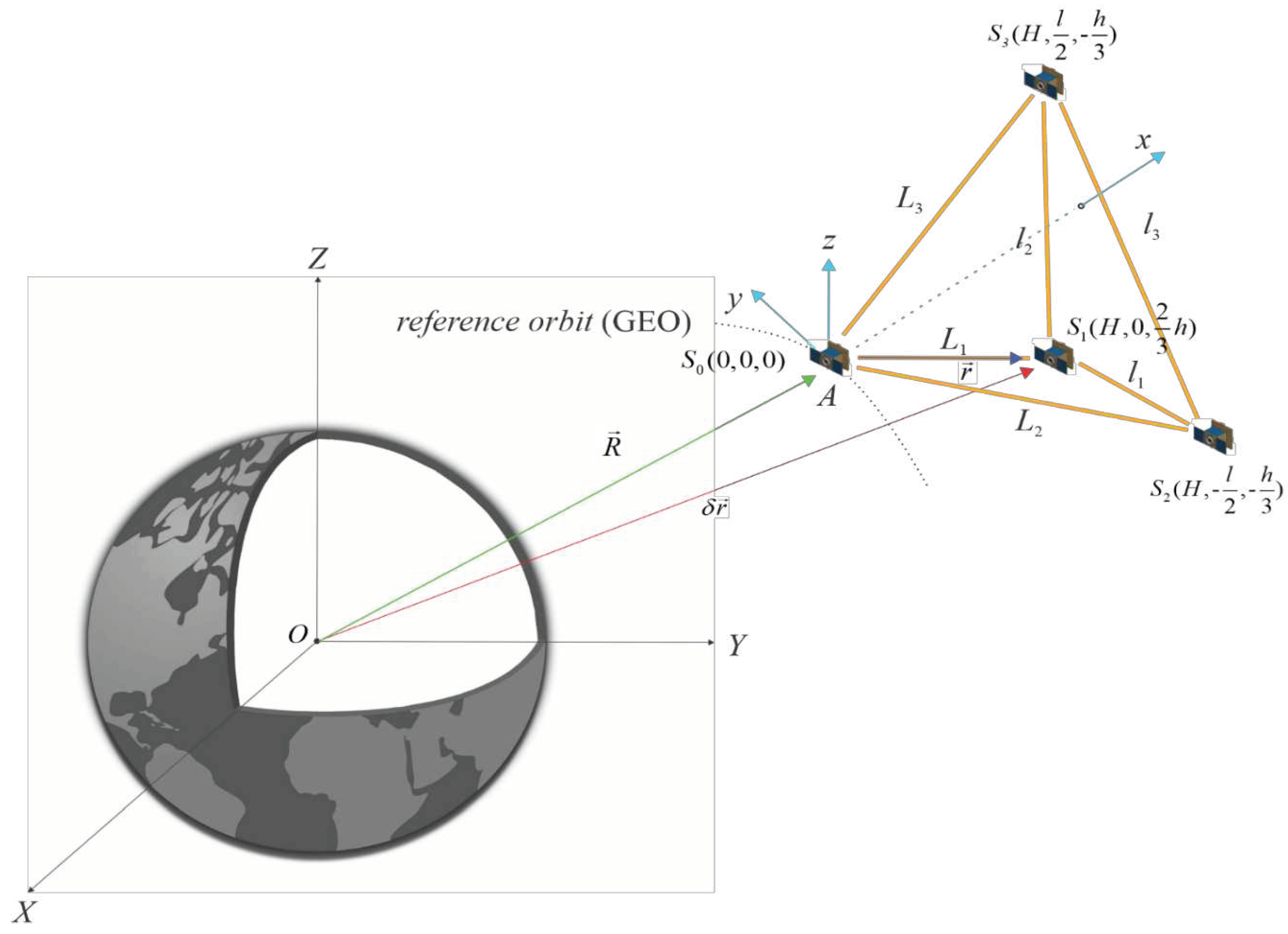
The satellite formation flying represents the synthetic aperture telescope for forest fire monitoring and consists of four satellites forming a tetrahedron or regular pyramid. The imaging satellite
S0 is located above the three mirror satellites
S1,
S2,
S3 located in the plane of the tetrahedron base and moves in an orbit called the reference orbit (
Figure 1). The mirror satellites
S1,
S2,
S3 form a regular triangle, and the height of the tetrahedron passes through the center of this triangle.
For monitoring the fire area in this work it was assumed that the ground sample distance (GSD) should be equal to 30 m. To achieve this value of GSD the distance between the plane with mirror satellites and imaging satellite that corresponds to the focal length of the telescope is assumed to be equal to 21.6 m, distance between mirror satellites affecting the aperture of telescope is assumed to be equal to 26.5 m.
The utilization of distributed satellite systems for aperture synthesis presents new opportunities for Earth monitoring from space. Nevertheless, this approach also introduces novel hurdles in maintaining the satellite formation flying geometry under action of disturbances. In this work the gravitational perturbations due to non-sphericity and inhomogeneity of Earth represented by zonal harmonic is considered in the process of derivation of relative dynamic model for the satellite formation.
In the
Figure 1 are shown following coordinate systems for describing the motion of satellite formation:
OXYZ - inertial coordinate system (ICS), the center of which is located at the Earth's center of mass, the OZ axis is directed along the Earth's rotation axis, the OX is directed to the point of the Spring equinox of the J2000 epoch;
Axyz – local vertical local horizontal (LVLH) coordinate system, the center of which is in the reference satellite represented by imaging satellite, the Ax axis is directed along the radius vector of the reference satellite from the center of the Earth, the Az axis is normal to the orbit plane in the direction of the orbital momentum, the Ay axis completes the system to the right handed system.
As it is known [
33] to take into account the inhomogeneity of the Earth's gravitational field represented by
zonal harmonic we need to write the gravitational potential in the following form:
where
is the radius of the Earth,
is the radius vector of the reference satellite in the ICS,
is the latitude of the reference satellite in the ICS.
Further using (1) the equations of satellite motion in formation relative to the reference satellite in LVLH frame was derived in [
33] in the form:
where
is the position of satellite in LVLH (position of imaging satellite),
I is the inclination of orbit of reference satellite,
is the inclination of the deputy satellites in formation represented by mirror satellites,
is the initial value for coordinate
z in relative position of satellites in formation,
the initial value of the velocity on the
z axis,
R is the radius-vector of reference satellite in ICS,
i is the deputy satellite number.
To determine the deviation of the current geometrical configuration from the tetrahedral one we introduced the volume of the tetrahedron [
34]:
where
=
,
=
,
=
are relative distances between the imaging satellite and mirror satellites in LVLH.
3. Analysis of Uncontrolled Motion of Tetrahedral Satellite Formation
At first the study of dynamics of passive uncontrolled motion of formation flying was performed. To assess the "run-up" (or "drift") of satellites in a formation during flight without control, graphs of changes in the distances between the reference imaging satellite -
S0 and mirror satellites
S1,
S2 and
S3 (
Figure 2,
Figure 3,
Figure 4,
Figure 5,
Figure 6,
Figure 7,
Figure 8 and
Figure 9), and a graph of changes in the configuration volume (
Figure 10) were obtained in the process of numerical simulation. All of these graphs represent the accuracy of relative positioning of satellites in the formation in case of perturbed uncontrolled motion.
The initial position and initial velocity of satellites in formation are given in
Table 1. The required geometrical configuration of satellite formation corresponds to the initial position of satellites given in the table.
It is assumed that the reference unperturbed orbit of the imaging satellite has following parameters: the radius of the circular orbit is 42164 km, the inclination
,
For simplicity of analysis of numerical simulation the following parameters was introduced:
- the magnitude of distance between the imaging satellite and the mirror satellite , ;
- the magnitude of distance between the mirror satellites , ;
- the magnitude of required distance between the imaging satellite and the mirror satellite , ;
- the magnitude of required distance between the mirror satellites , ;
- the magnitude of relative position error of the mirror satellite relative to imaging satellite, , ;
- the magnitude of relative position error of the mirror satellites, ;
- the magnitude of the formation volume deviation from the required value,
- the magnitude of the tetrahedral formation height deviation from the required value, .
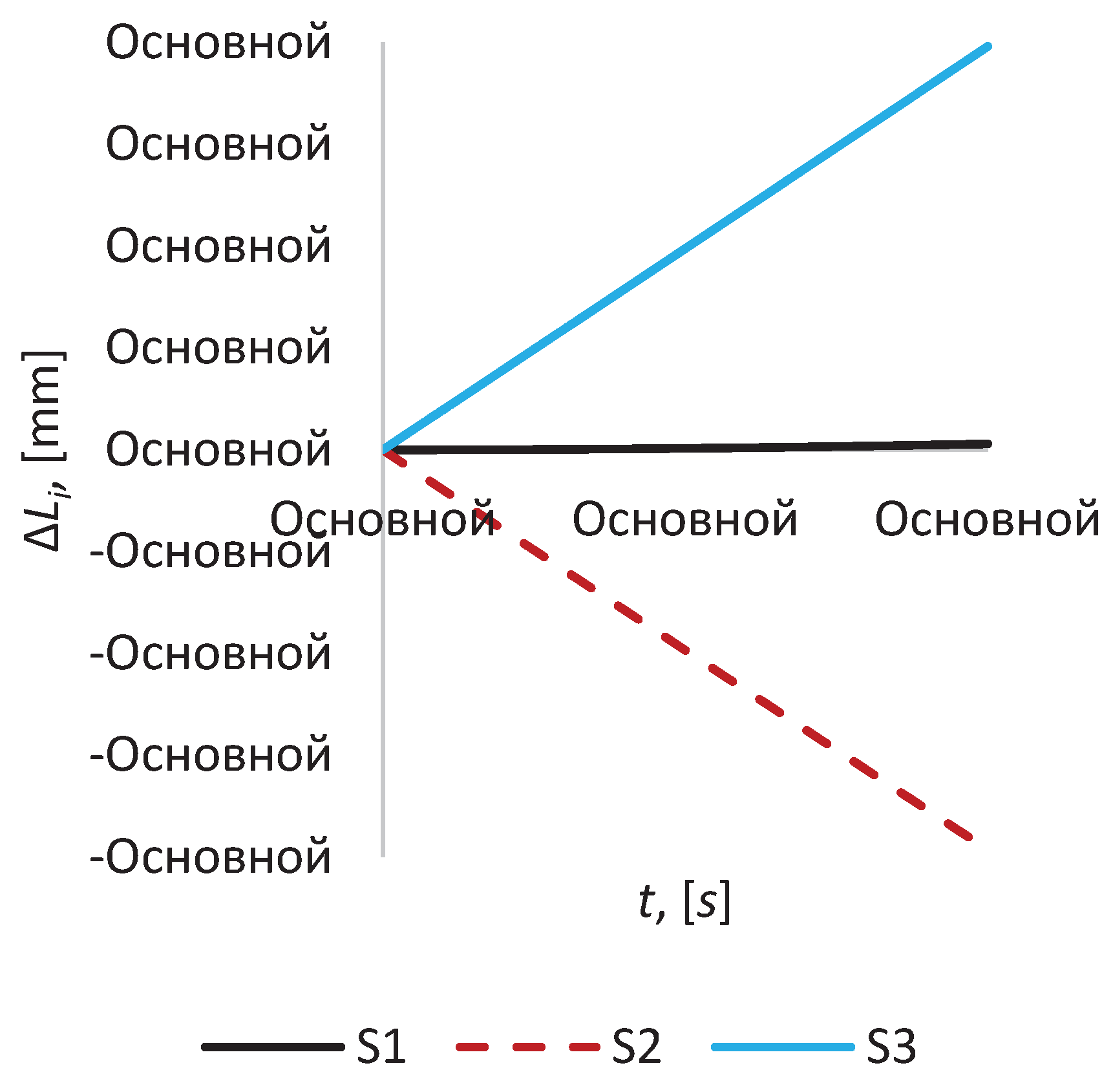
Changing of the relative position error of the mirror satellite relative to imaging satellite for time intervals, i.e. up to 100 seconds, is ambiguous for each mirror satellite (
Figure 2). For example, the most intense change in distance is observed for
S2 and
S3, i.e. for the mirror satellites
S2 and
S3, and at 100 seconds it reaches the values of 26.421 m and 26.579 m, respectively. The distance between satellites
S0 and
S1 changes much more slowly; for example, at t = 100 s it equals 26.501 m. Thus, the relative position error for
S2 and
S3 is 7.9 cm (or Δ
L2 = -7.9 cm, Δ
L3 = +7.9 cm, where the minus sign means that the satellite is moving towards reference point of the local coordinate system, see
Figure 2), while for
S1 it is 1 mm (or Δ
L1 = +1 mm, see
Figure 2).
Figure 2.
The relative position error for the time interval 100 s.
Figure 2.
The relative position error for the time interval 100 s.
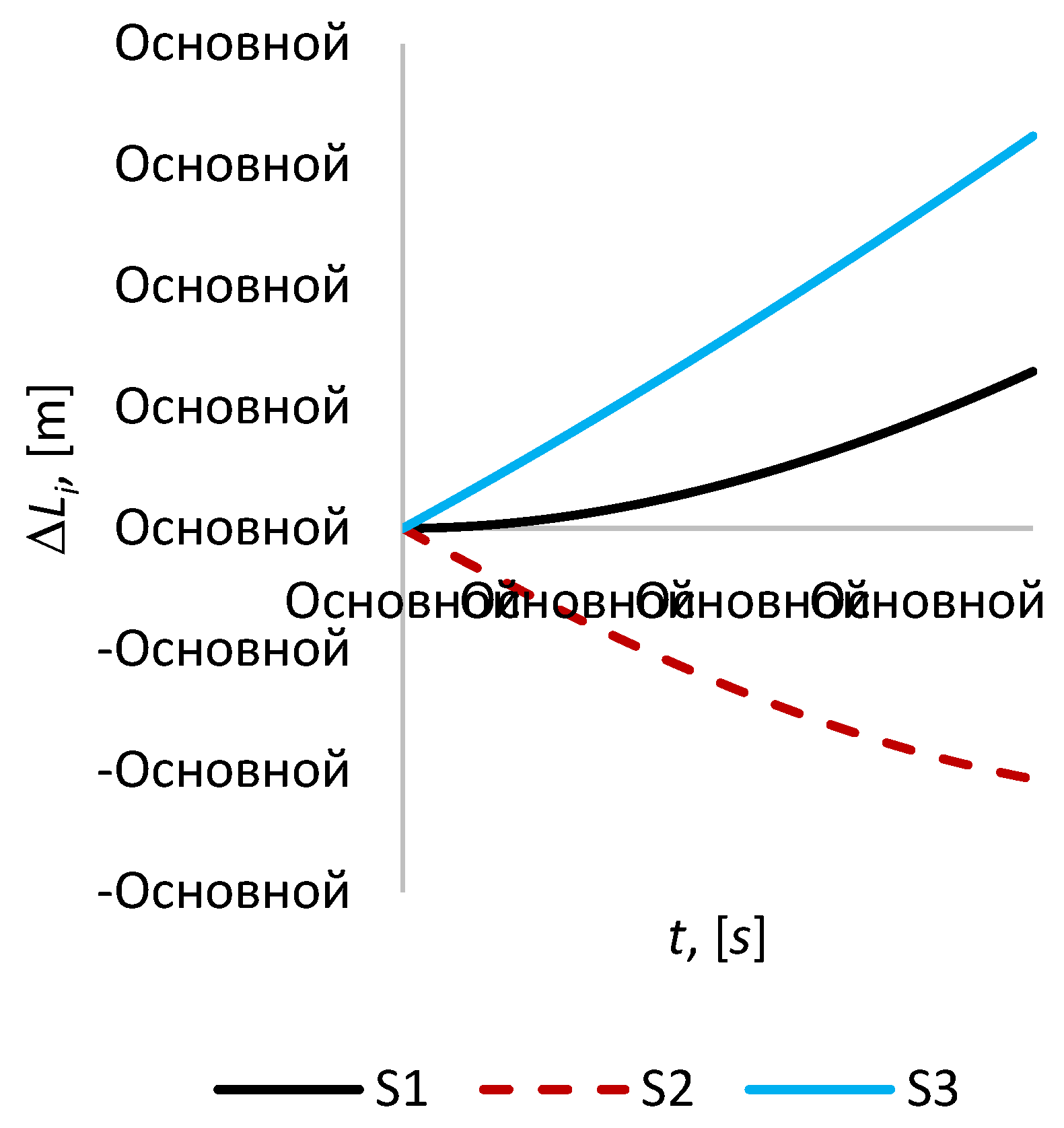
In the case of a passive flight of the formation without control for an hour (see
Figure 3), the displacement of
S2 continues up to a value of 2.1 m. Δ
L1 increases with lesser intensity, for example, at
t = 3600 with Δ
L1 = +1.3 m. Whereas within an hour Δ
L3 reaches 3.2 m, i.e. in this case, in this case Δ
L3 is already greater than Δ
L1 by almost 2.5 times. Based on this, it can be assumed that at longer time intervals, the mirror satellite
S1 will move away more intensively, while the satellite
S2 at some point in time will leave a stable orbit while keeping its constant value, or will reapproach the imaging satellite
S0.
Figure 3.
The relative position error for the time interval 3600 s.
Figure 3.
The relative position error for the time interval 3600 s.
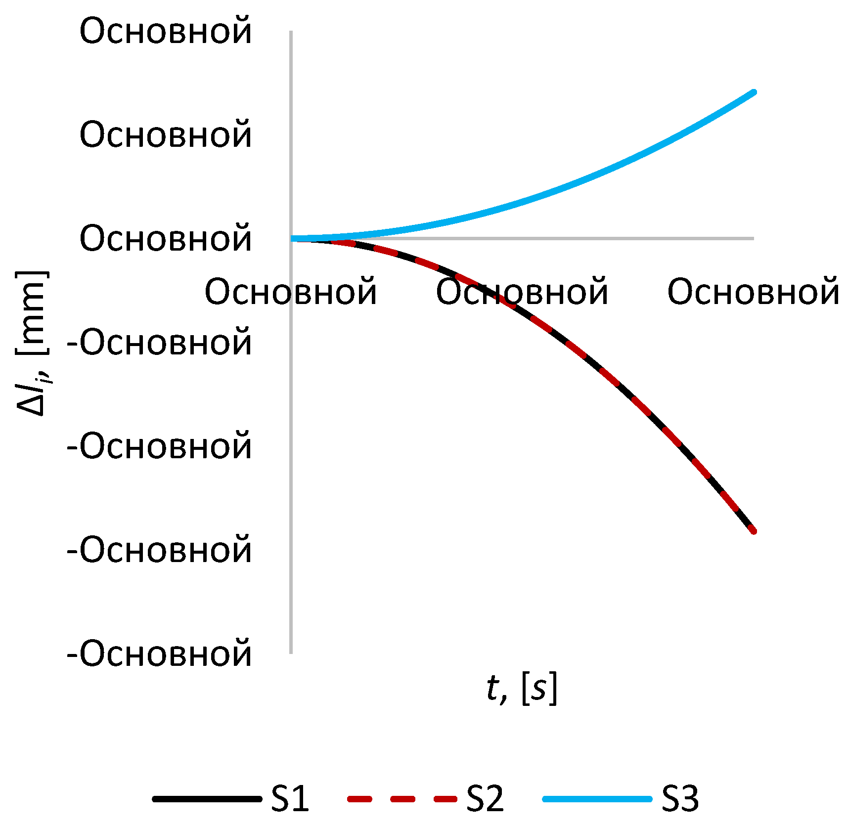
In the case of passive flight, the change in the distance between mirror satellites
S1,
S2 and
S3 at short time intervals, i.e. at
t ≤ 3600 s is much less than the case of changing the distances between the imaging satellite and mirror satellites (
Figure 4). For example, at
t = 100 s, the maximum values for satellites
S1,
S2 and
S3 are Δ
l1 = Δ
l2 = –1.4 mm, Δ
l3 = + 0.7 mm, which is almost 56 and 113 times less than the cases of
ΔL2 and
ΔL3, while the change in Δ
l1 and Δ
L1 comparable.
Figure 4.
The relative position error for the time interval 100 s.
Figure 4.
The relative position error for the time interval 100 s.
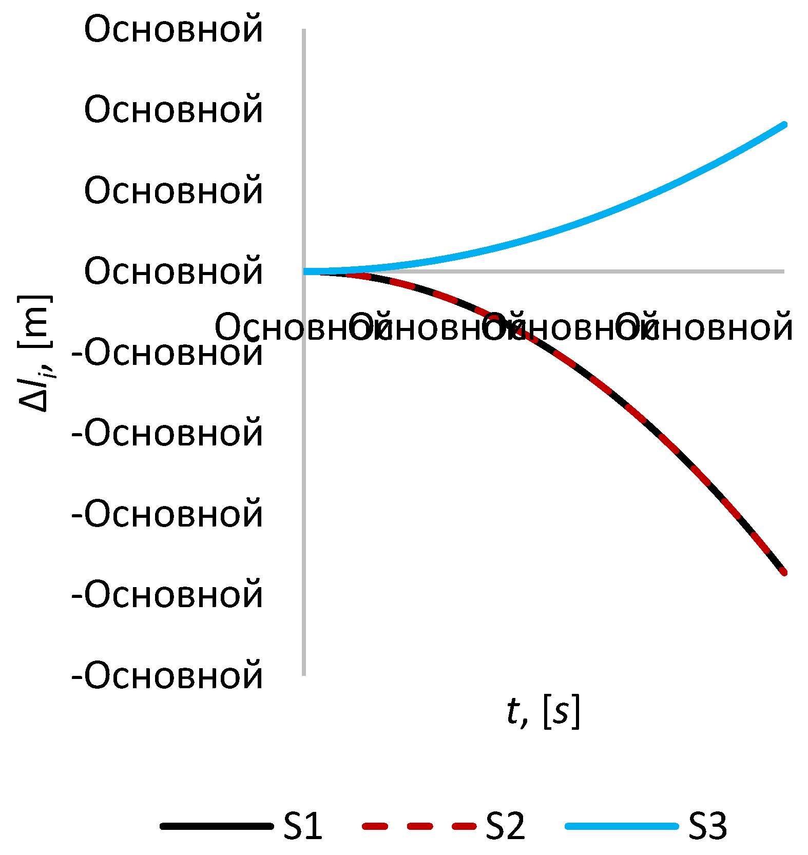
At
t = 3600 s, the magnitude of the distances between the imaging and mirror satellites, and between the mirror satellites become almost the same order (
Figure 5). For example, Δ
l2 = –1.9 m, which is only 1.1 times less than Δ
L2, respectively, Δ
l3 = + 0.9 m, which is 3.56 times less than Δ
L3. For the distances between the satellites
S0 and
S1, and between
S1 and
S2, the opposite picture is observed, in this case Δ
l1 = –1.9 m, which is already 1.46 times greater than Δ
L1.
Figure 5.
The relative position error for the time interval 3600 s.
Figure 5.
The relative position error for the time interval 3600 s.
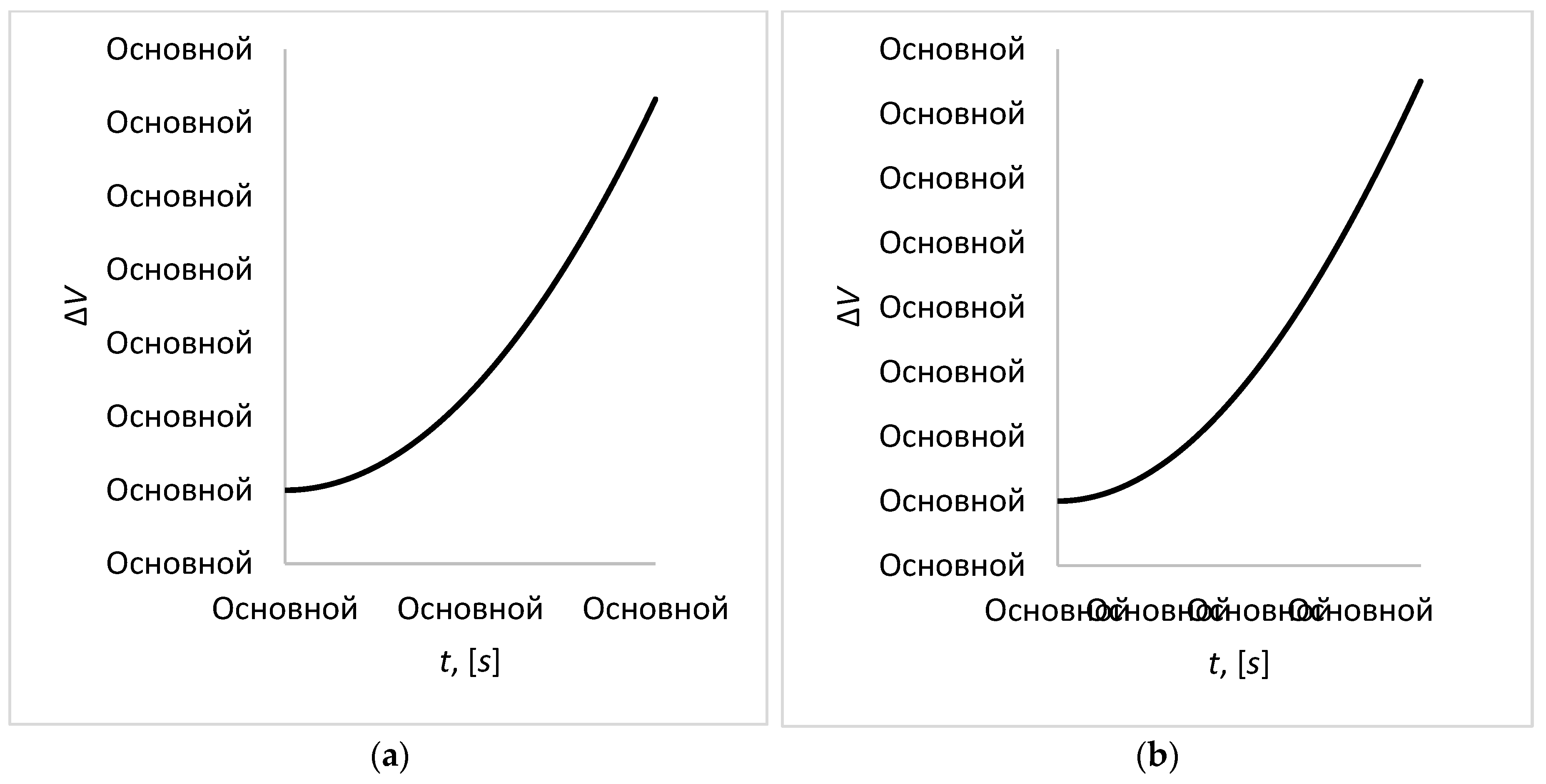
As mentioned above, to assess the “run-up” of satellites in a formation during flight without control, or in other words, to assess the keeping of the formation volume, graphs of volume deviation from the required value were plotted for different time intervals ranging from 100 seconds to 1 hour. For example, with ΔV = 1, we can conclude that the volume has not changed from the initial value.
For short time intervals, a slow but monotonous increase in volume is observed (
Figure 6, cases (a) and (b)). For example, at 100 seconds, the volume increases by only 0.005% compared to the required value (
Figure 6, case (a)), while with an hour of passive flight, this value already reaches 6.5% (
Figure 6, case (b)). For most tasks, these volume fluctuations are insignificant, and should in no way affect to the successful completion of the mission, which cannot be admissible for the formation representing the synthetic aperture telescope. This mission requires relative position accuracy of about 0.1-1μm, which leads to active control of the formation in the early stages of the motion.
Figure 6.
The magnitude of volume deviation from the required value for different time intervals, cases: (a) t = 100 s, (b) t = 3600 s.
Figure 6.
The magnitude of volume deviation from the required value for different time intervals, cases: (a) t = 100 s, (b) t = 3600 s.
Table 2.
Table of maximum values for relative position errors of satellites.
Table 2.
Table of maximum values for relative position errors of satellites.
| t |
max(ΔL1) |
max(ΔL2) |
max(ΔL3) |
max(Δl1) |
max(Δl2) |
max(Δl3) |
| 0-100 s |
+1 mm |
-7.9 сm |
+7.9 сm |
-1.4 mm |
-1.4 mm |
+ 0.7 mm |
| 0-3600 s |
+1.3 m |
-2.1 m |
+3.2 m |
-1.9 m |
-1.9 m |
+ 0.9 m |
4. Control System for Tetrahedron Satellite Formation
As it was stated earlier, in this paper we consider the problem of developing a control system for a tetrahedral satellite formation flying in the geostationary orbit for high temporal and spatial resolution monitoring of fire in the forest area of Kazakhstan.
The satellite formation flying forms a synthetic aperture telescope operating in infrared range. The main task that is solved by this formation control system is to keep the formation geometrical configuration with a µm-class accuracy. In particular, relative position error of mirror satellites in tetrahedral formation should be kept within a range of 0.1-1 µm.
The equations for the controlled motion of a satellite in a formation has the form (2) with the control forces assumed as the linear function
where
are required position of satellite in formation relative the reference coordinate system,
are relative velocity of satellites in formation,
,
,
are constant coefficients.
To determine the unknown feedback coefficients , , in expressions for the control acceleration (9) we applied several approaches of linear control theory:
1) root method (RLM) providing the required response speed, damping and stability of the system;
2) linear quadratic regulator (LQR) minimizing the state error and control effort of the system;
3) optimal control minimizing the system's sensitivity to disturbances;
4) optimal control providing the robustness of the system to disturbances;
5) mixed control allowing the flexible trade-off between performance and robustness.
Let’s consider every approach in detail.
Root method (RLM)
At the first stage we considered the classical approach for the root method providing the special location of the closed-loop poles of the system in the complex plain.
As can be seen from (9) the third equation of the system does not contain the variables included in the first and second equations, then it can be considered individually. We will look for a solution to the equation in the form:
From here we find the corresponding
,
and introduce the corresponding values into the third equation of system (2). Making transformations we obtain an algebraic equation:
Obviously, equation (12) is a polynomial of the second degree of the form:
Consider the first and second equations of system (2). We will look for their solutions in the form:
From here we find the corresponding time derivatives and put them into the equations of system (2). Making transformations, we obtain the corresponding system of algebraic equations:
Since the system of equations (14) must have a non-zero solution for A and B, the determinant of this system is equal to zero:
or
We define the required roots of the second-order characteristic equation as the roots of the Butterworth polynomial since it provides maximally flat and monotonic transition process [
35] in the form:
where
,
is the normalized time of the transient process,
is the real time of the transient process.
And the roots of the characteristic equation of the fourth order as the roots of the Butterworth polynomial in the form:
The roots of Butterworth polynomial locate on the circle of radius in the left half of complex plain.
Further equating in formulas (12) and (18) terms at the similar power of
we obtain expressions for determining the unknown feedback coefficients:
Equating in formulas (17) and (19) terms at the similar power of
we obtain a system of algebraic equations for determining the unknown feedback coefficients:
At the following stage we considered another approach for the root method proving the location of the closed-loop poles of the system in LMI regions.
LMI regions are convex subsets D of the complex plane characterized by [
36]:
where
and
are fixed real matrices. The matrix-valued function
is called characteristic function of the region
.
The approach of control synthesis as the function
that provides the robust pole placement in LMI regions usually is considered for the linear systems of the type:
where
is the state vector of the system,
is the exogenous input,
is control,
is the regulated output,
is the measured output.
The closed-loop poles of (24) lie in the LMI region (22) if and only if there exists a symmetric positive definite matrix
satisfying [
36]:
with the notation
.
LMI region can be represented individually or as intersection of several LMI regions. In this article this region is given as the intersection of a disk of radius
with origin at the point
and a conical sector with inner angle
:
The matrices of equation (24) used for synthesis of controller has the following form:
Linear quadratic regulator (LQR)
The second method to synthesize the controller for keeping the satellite formation with high accuracy is a linear quadratic regulator (LQR), which is obtained by minimizing the quality criterion of the form [
37]:
where
, Q, R are positive matrices with constant components,
,
,
- is the required position of the satellite in a formation.
The control acceleration
] for the linear system in the form (24) obtained as result of minimizing the performance criterion (31) has the form [
37]:
where
introduced in (28), the matrix R has the form:
And the matrix P can be determined from the equation:
where
,
are the matrices introduced in (28), the matrix Q has the form:
optimal control
optimal controller is considered for the linear systems with a state space representation similar to (24):
where
.
The state feedback synthesis control problem reduces to developing a controller
that minimizes the
norm of the transfer function
[
38]:
To calculate this norm we need to solve the following problem [
38]:
Introducing
,
,
and using appropriate transformations (38) is equivalent to LMI problem:
Using the matrices , , , , introduced in (28), (29), (30) and finding satisfying (39) the state feedback gain matrix is calculated as .
optimal control
optimal controller is considered for the linear systems with a state space representation similar to (24). The state feedback synthesis control problem reduces to developing a controller
that minimizes the
norm of the transfer function
[
39]:
To calculate this norm we need to solve the following problem [
39]:
Introducing
,
and using appropriate transformations (41) is equivalent to:
Using the matrices , , , , introduced in (28), (29), (30) and finding satisfying (42) the state feedback gain matrix is calculated as .
Mixedcontrol
Mixed
control is considered for the linear systems with a state space representation:
where
is the state,
is the control,
is the output, where
is the
performance channel,
is the
performance channel.
Mixed
output feedback controller for the plant (43) can be obtained in the form [
40]:
This controller stabilizes the system exponentially, the performance channel has a performance level , the performance is minimized among all stabilizing the system exponentially and having prescribed performance level .
Thus, the mixed
-synthesis problem is the optimization program [
40]:
where
denotes the transfer function of the
closed-loop performance channel,
denotes the transfer function of the
closed-loop performance channel,
is a threshold.
The solution of presented problem is presented in [
40].
The matrices
,
,
,
,
,
,
,
,
,
,
used for synthesis of
controller has the following form correspondingly:
5. Results and Discussion of Numerical Simulation of Tetrahedron Satellite Formation under Control
Numerical modeling of the satellite formation dynamics was carried under action of RLM, LQR,
,
controllers, mixed
controllers. Initial conditions for numerical integration and initial geometrical configuration are given in
Table 1. The problem of keeping the actual positions of satellites in this initial geometrical configuration is considered in this section.
For numerical simulation it was assumed that the reference unperturbed orbit of the imaging satellite has the following parameters: the radius of the circular orbit is 42000 km, the inclination .
As in the section 3, for simplicity the following parameters are used in this section for the description of numerical results:
- the relative position error of the mirror satellite relative to imaging satellite, , ;
- the relative position error of the mirror satellites, ;
- magnitude of the formation volume deviation from the required value, ;
- magnitude of the tetrahedral formation height deviation from the required value, .
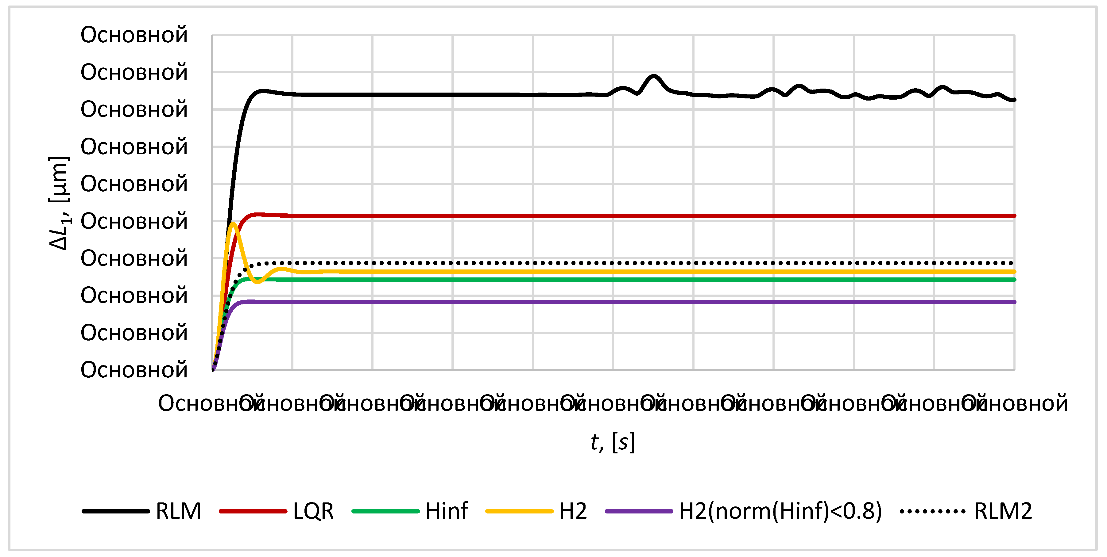
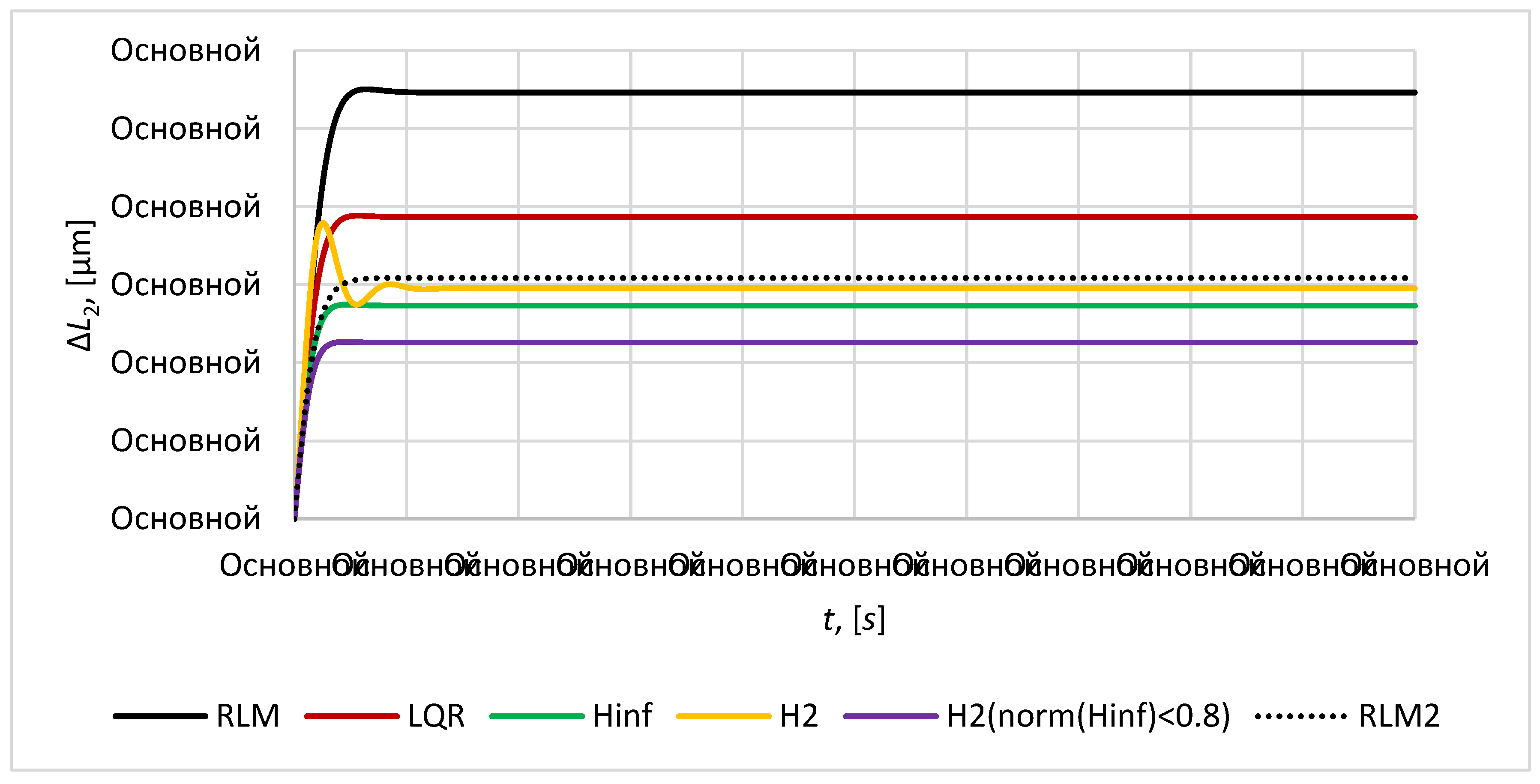
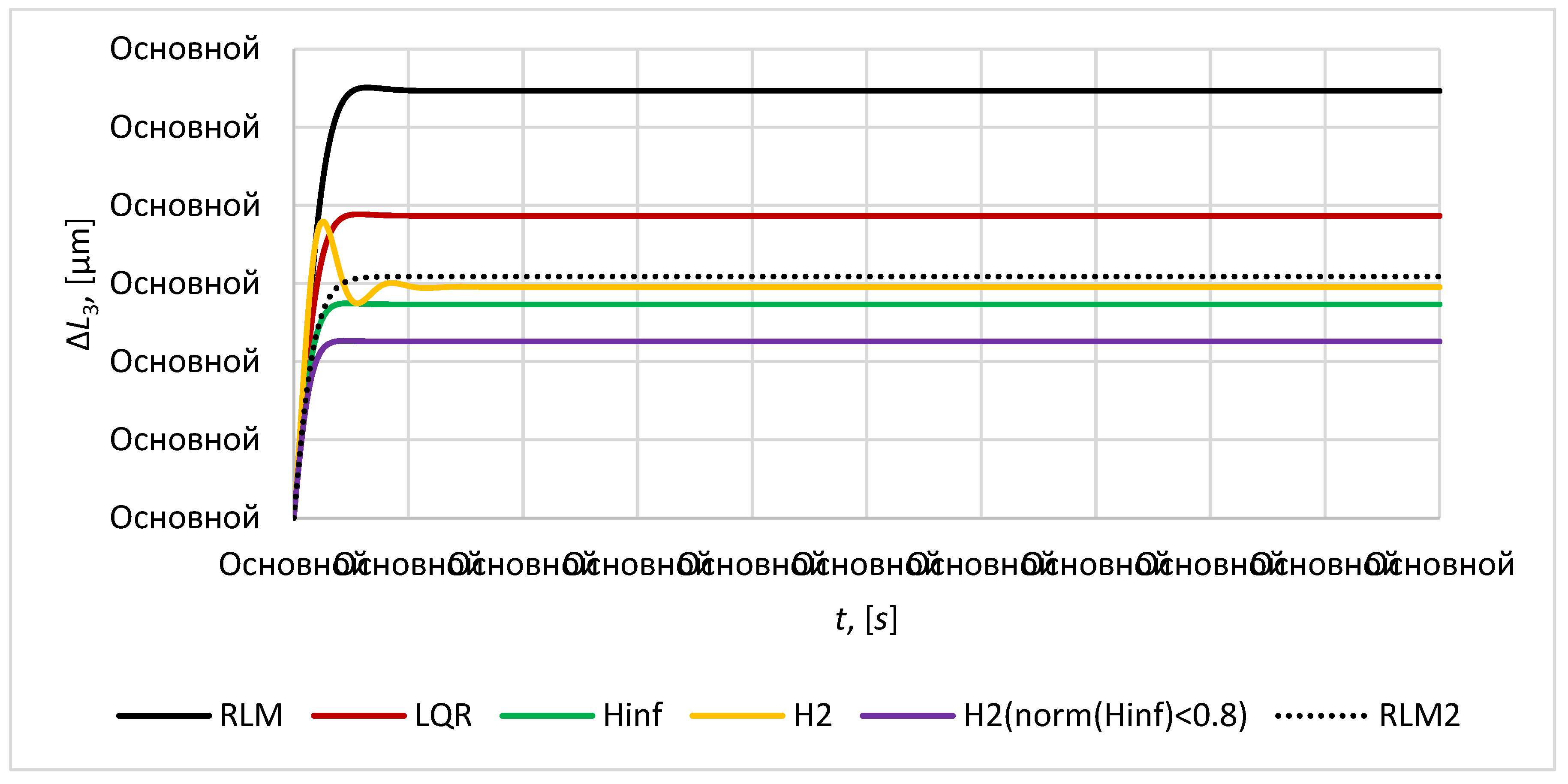
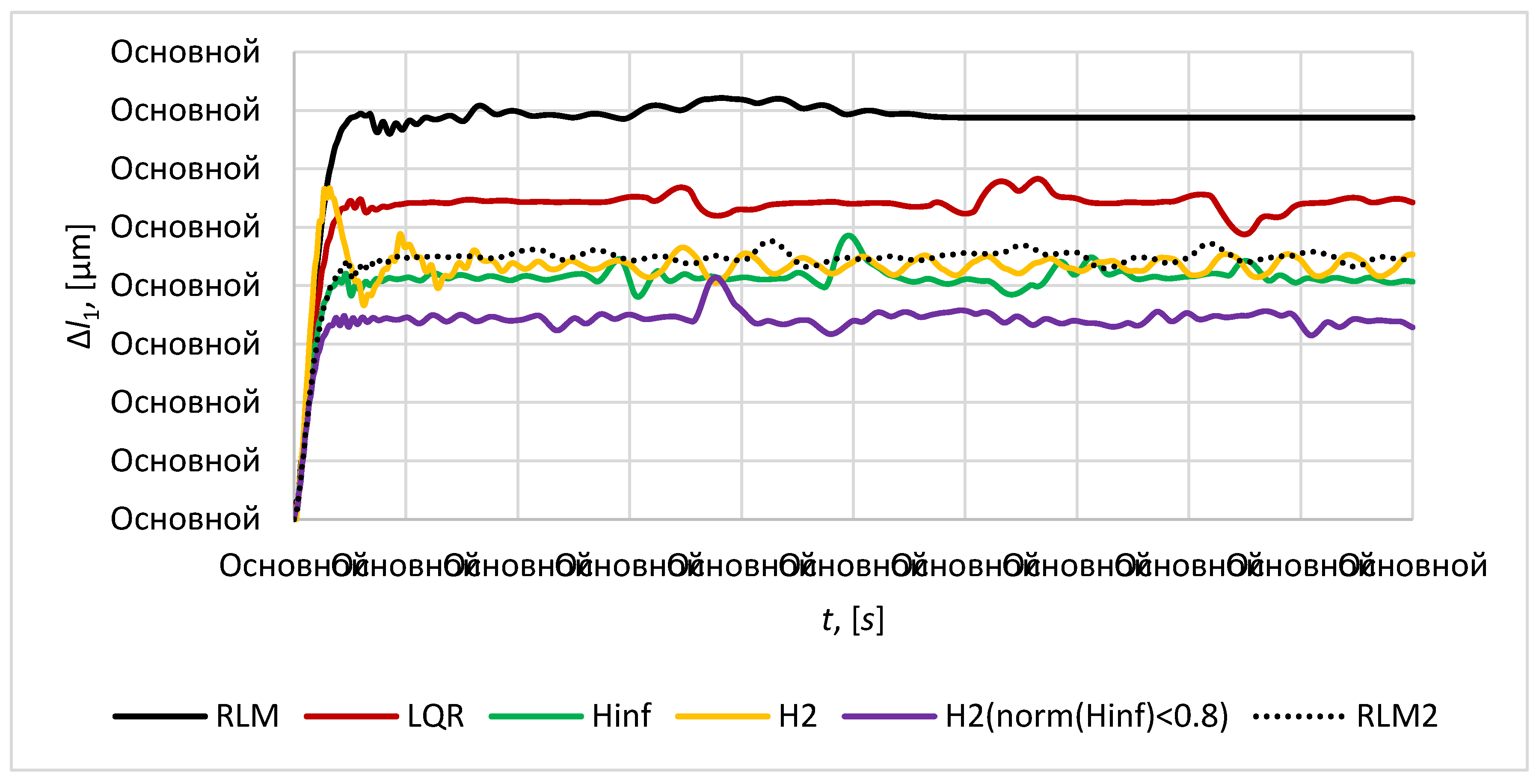
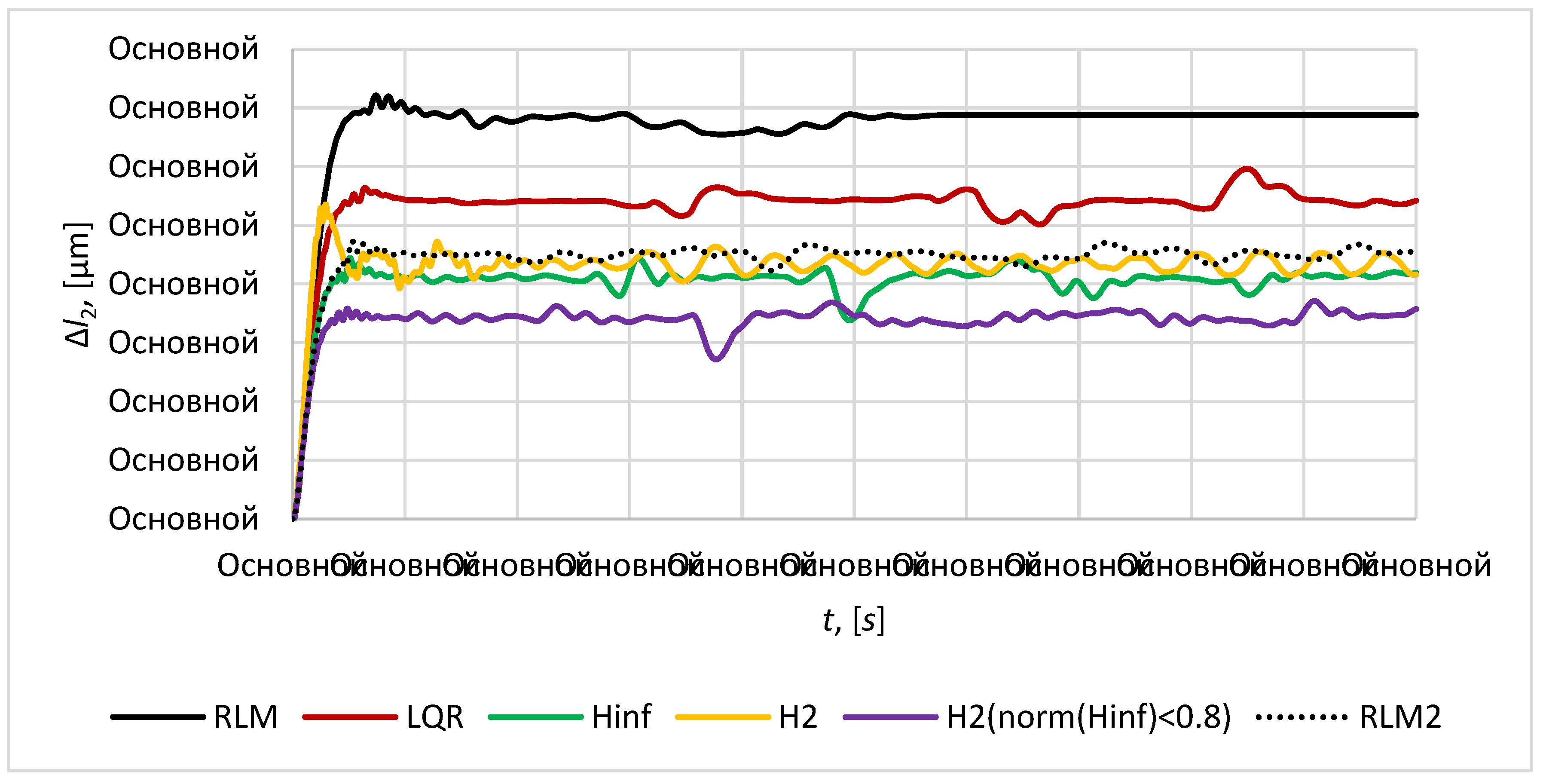
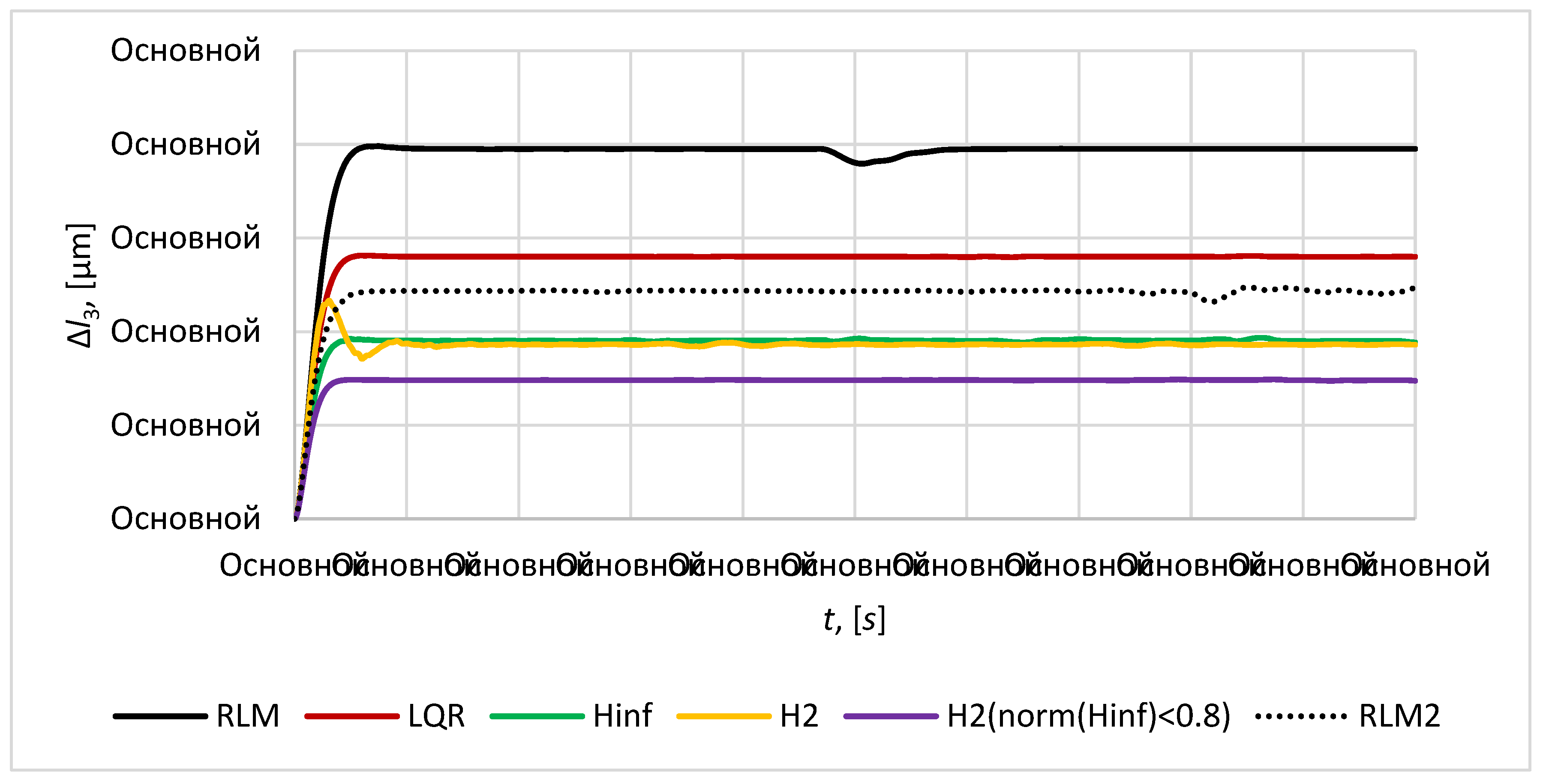
The plots of relative position error
of the mirror satellite
relative to imaging satellite
are given in the
Figure 7,
Figure 8 and
Figure 9. The required distance between the imaging satellite and the mirror satellite
is taken as
.
The plots of the relative position error
of the mirror satellites are given in the
Figure 10,
Figure 11 and
Figure 12. The required distance between the mirror satellites
is taken as
.
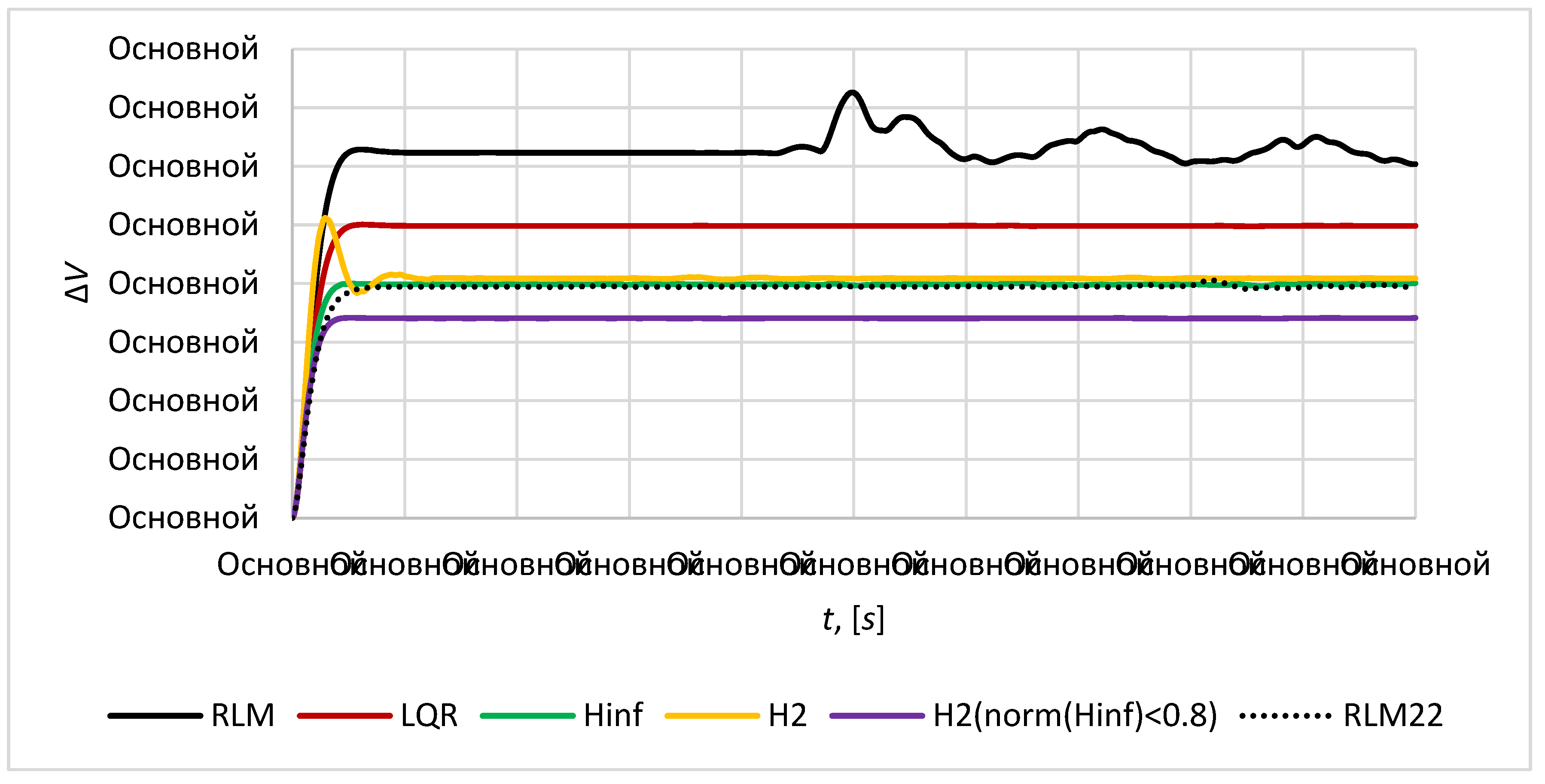
The plot of magnitude of the formation volume deviation
from the initial required value
is given in the
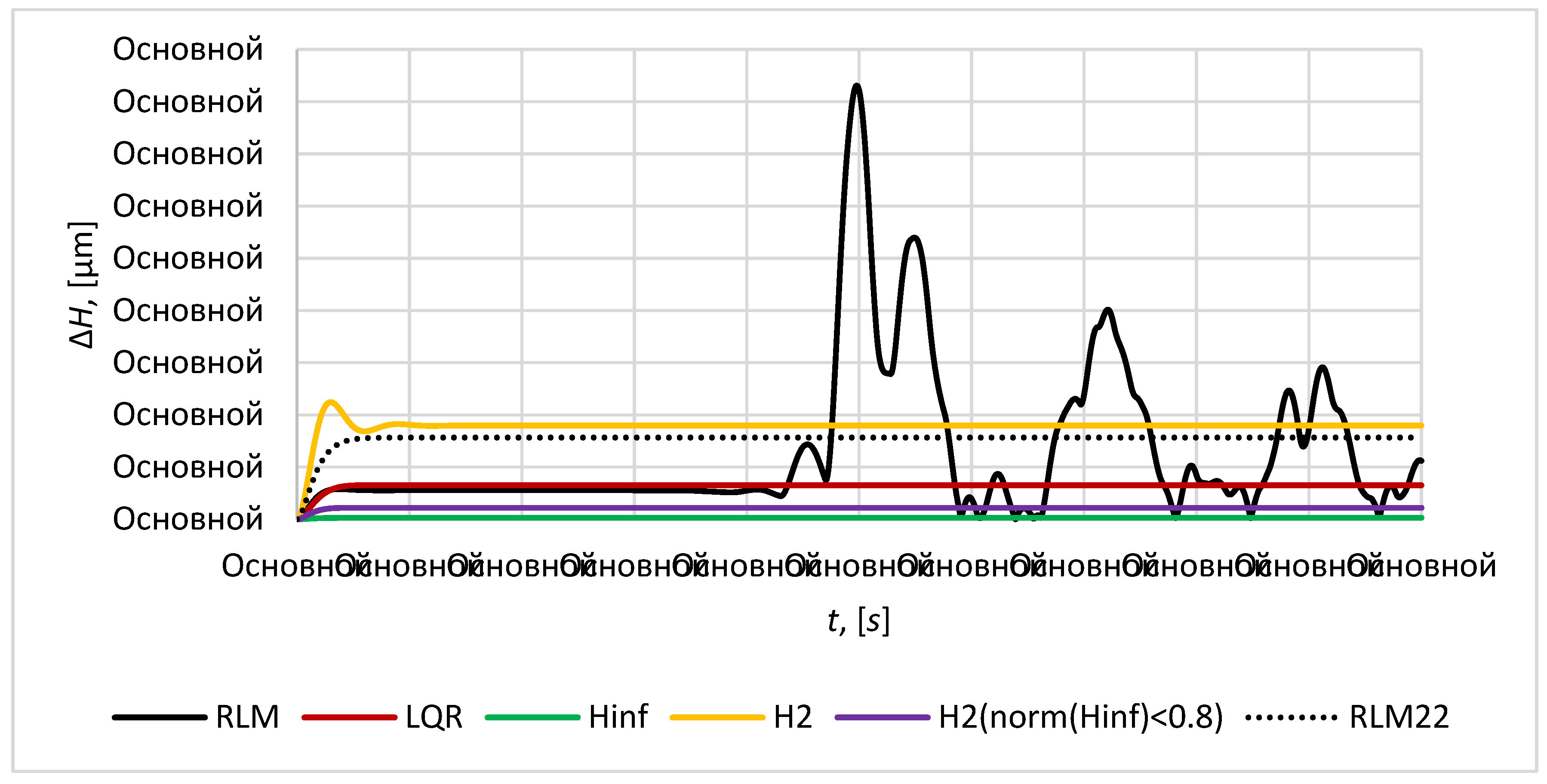
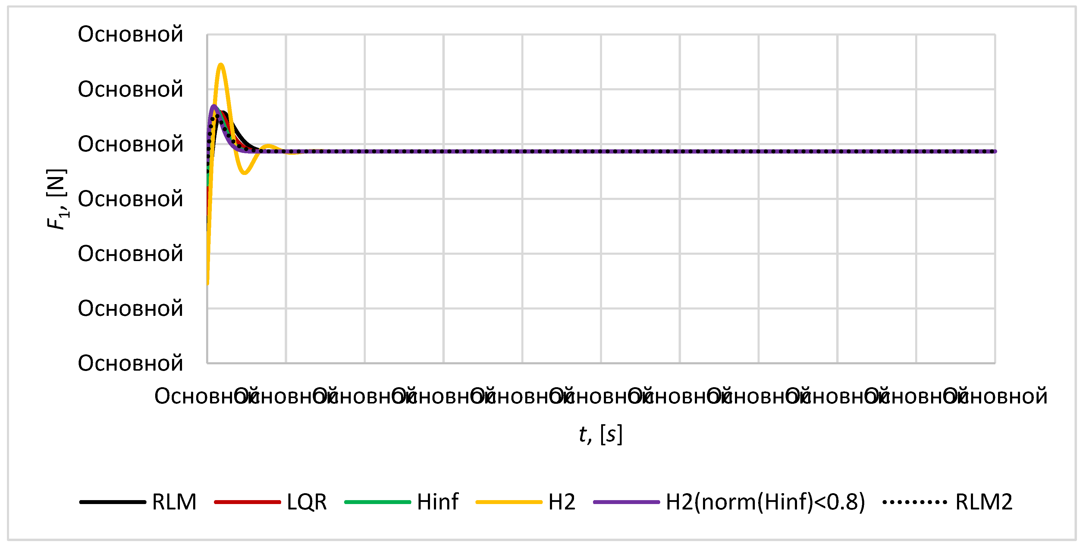
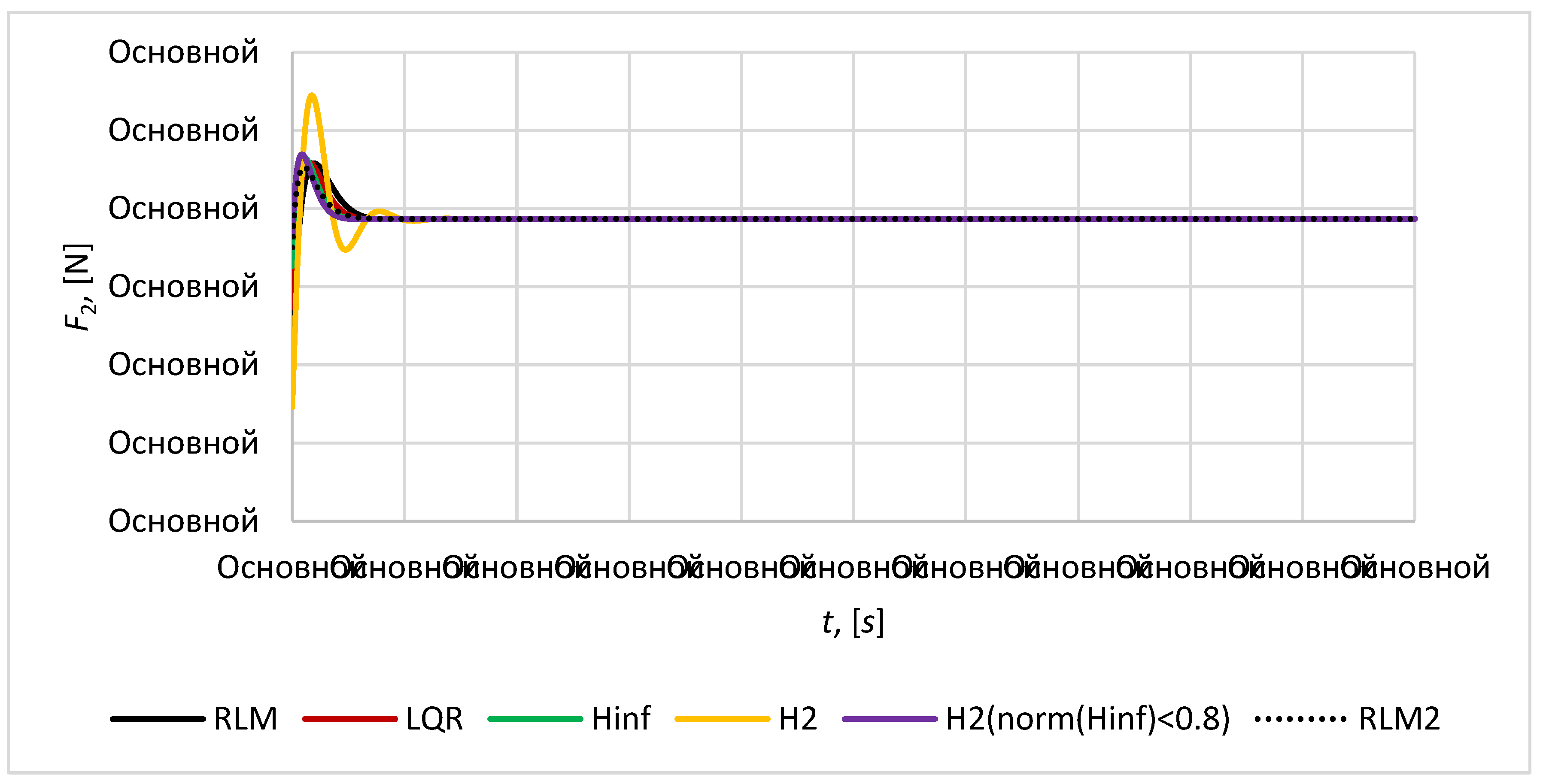
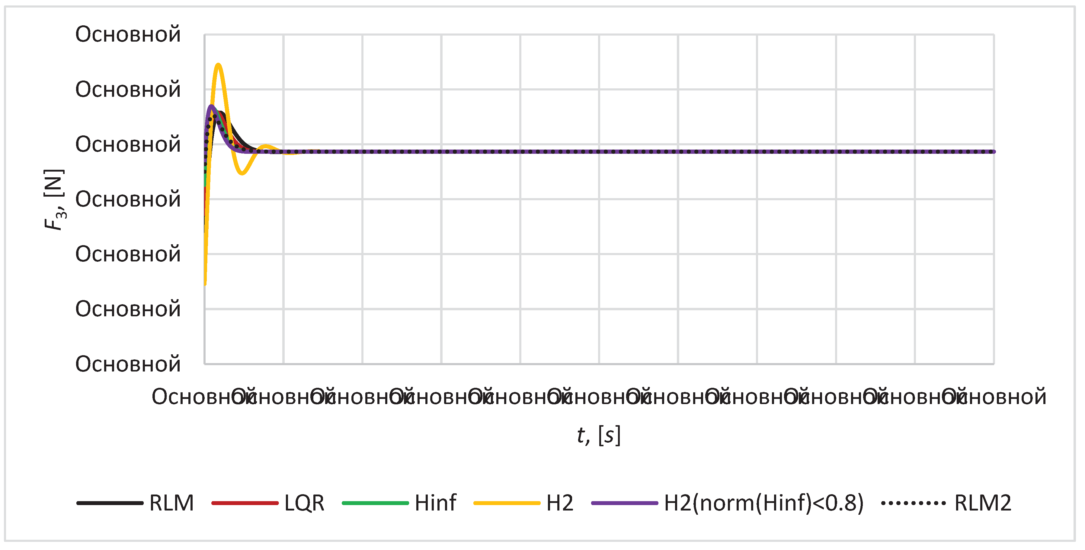
Figure 13. The magnitude of control force for imaging satellites
are given in the
Figure 15,
Figure 16 and
Figure 17. Below in
Table 3 are given the results of analysis of controllers:
- the quality analysis of these controllers on the base of the parameters of accuracy, transient time, overshoot, damping character;
- quality analysis of the satellite formation configuration based on the volume character of the formation;
- analysis of control effort for keeping the configuration with required accuracy.
In accordance with the results of simulation modeling mixed
controller provides best results in terms of transient time and accuracy, as the maximum relative position error for mirror satellites is 0.17
and maximum relative position error for mirror satellites relative to imaging satellite is 1129
under the maximum control effort of 0.231 N. This control provides the minimal changes in height and volume of satellite formation (
Figure 13 and
Figure 14) that guarantee the keeping of formation configuration in tetrahedral form with high accuracy.
controller shows the similar results in accuracy, transient time, control effort, character of volume and height of satellite formation. It provides the maximum relative position error for mirror satellites of 0.20
and maximum relative position error for mirror satellites relative to imaging satellite of 1366
. Mixed
controller gives better accuracy and performance in the process of keeping the configuration as it combines the advantages of
and
control techniques. In contrast the pure
controller results in oscillatory character of relative distances variation between the satellites and doubles the transient time (
Figure 7,
Figure 8,
Figure 9,
Figure 10,
Figure 11 and
Figure 12), whereas the maximum relative position error for mirror satellites is 0.21
and maximum relative position error for mirror satellites relative to imaging satellite is 1477
under the maximum control effort of 0.271 N. This accuracy is close to
controller, but damping character of transient process is worse.
LQR controller shows good results in stabilization of transient process, stability of volume and height of the satellite formation, but in contrast to controller and mixed controller it provides worse accuracy: the maximum relative position error for mirror satellites is 0.27 and maximum relative position error for mirror satellites relative to imaging satellite is 1932 .
For the root method (RLM) two approaches of poles placement in complex plane is considered in this paper and corresponding RLM controller and RLM2 controller was obtained. RLM controller provides the placement of poles of control system on the circle of radius 1.2 in left part of complex plane. RLM2 controller provides the placement of poles of control system in the region bounded by a disk of radius 2 with origin at the point (-2, 0) and a conical sector with apex at the point (-0.1,0) and inner angle
. This technique allows to achieve good transient process quality such as transient time and damping characteristics. RLM2 controller provides the accuracy similar in values to
and
controllers: the maximum relative position error for mirror satellites is 0.22
and maximum relative position error for mirror satellites relative to imaging satellite is 1544
. RLM is worse in accuracy. Both RLM and RLM2 controllers provide almost the similar transient time 9-10 seconds, but in contrast to other considered here controllers it is more sensitive to disturbances, that results in non-permanent character of satellite formation volume and height (
Figure 13 and
Figure 14) and it can lead to the violation of tetrahedral configuration which is not valid for a mission presented in this article.
The analysis made it possible to conclude that
controller and mixed
controller is the most appropriate for providing the satellite formation mission that forms a telescope for remote sensing, since it provides the necessary accuracy of satellite relative positioning, the quality of transient processes and keep the configuration with the high accuracy. Regarding the results of simulation and thrust calculation (
Figure 15,
Figure 16 and
Figure 17) in case of using cold gas thrusters with specific impulse 70 seconds the necessary fuel consumption for mirror satellite is 9.86 kg per year. It indicates the necessity to improve the controller for decreasing the amount of necessary fuel for satellites in formation.
Figure 7.
The relative position error .
Figure 7.
The relative position error .
Figure 8.
The relative position error .
Figure 8.
The relative position error .
Figure 9.
The relative position error .
Figure 9.
The relative position error .
Figure 10.
The relative position error .
Figure 10.
The relative position error .
Figure 11.
The relative position error .
Figure 11.
The relative position error .
Figure 12.
The relative position error .
Figure 12.
The relative position error .
Figure 13.
Magnitude of formation volume deviation .
Figure 13.
Magnitude of formation volume deviation .
Figure 14.
Magnitude of the tetrahedral formation height deviation .
Figure 14.
Magnitude of the tetrahedral formation height deviation .
Figure 15.
Magnitude of control force for satellite S1.
Figure 15.
Magnitude of control force for satellite S1.
Figure 16.
Magnitude of control force for satellite S2.
Figure 16.
Magnitude of control force for satellite S2.
Figure 17.
Magnitude of control force for satellite S3.
Figure 17.
Magnitude of control force for satellite S3.
6. Conclusion
The problem of development the control system for a satellite formation flying in the form of synthetic aperture telescope on the geostationary orbit for monitoring of fire in the forest area of Kazakhstan is considered in this paper. To achieve a high spatial resolution it was assumed that the formation has definite tetrahedral configuration in the form of synthetic aperture telescope operating in infrared range and consists of three mirror satellites and one imaging satellite. Synthesizing the image with good quality requires to keep the configuration of formation with µm-class accuracy and provide minimum volume deviation of the configuration from its required value. It has been shown that in uncontrolled flight volume conservation is not a sufficient condition for successful missions, since for a single configuration volume value there are many configurations. To obtain the best quality of images, it is necessary to keep the relative position of satellites with 0.1-1µm-class accuracy. Currently adaptive optics and MEMS deformable mirror can provide such accuracy. In this paper we focused on the synthetic aperture telescope using conventional mirrors and µm-class positioning accuracy.
To keep the configuration in the required form with µm accuracy the analysis of efficiency of various control methods, such as the root method (RLM), LQR, optimal control, optimal control and mixed control method, was carried out in the process of numerical simulation. The simulation results made it possible to highlight the following features of various approaches to the development of control system for the satellite formation flying representing a synthetic aperture telescope:
- RLM controllers is sensitive to disturbances, that results in non-permanent character of satellite formation volume and height and it can lead to the violation of satellite configuration which is not valid for a mission presented in this article;
- controller and mixed controller provide best results in terms of transient time and accuracy;
- LQR controller shows good results in stabilization of transient process, stability of volume and height of the satellite formation, but in contrast to controller and mixed controller it provides worse accuracy;
- controller results in oscillatory character of relative distances variation between the satellites and doubles the transient time.
Thus, in accordance with the results of analysis, it possible to conclude that controller and mixed controller is the most appropriate for providing the satellite formation mission that forms a synthetic aperture telescope for remote sensing, since it provides the necessary accuracy of satellite relative positioning, the quality of transient processes and keep the configuration geometry with the high accuracy.
Author Contributions
For research articles with several authors, a short paragraph specifying their individual contributions must be provided. The following statements should be used “Conceptualization, Z.R. and Sh.N.; methodology, A.S. and G.G.A.I.; software, G.G.A.I.; validation, Z.R., Sh.N. and A.S.; formal analysis, N.K.; investigation, A.S.; resources, A.S.; data curation, G.G.A.I. and N.K.; writing—original draft preparation, A.Z. and N.K.; writing—review and editing, A.Z. and A.S.; visualization, G.G.A.I. and N.D.; supervision, Z.R.; project administration, N.D.; funding acquisition, Z.R. All authors have read and agreed to the published version of the manuscript.”
Funding
This research was funded by the Ministry of Science and Higher Education of the Republic of Kazakhstan. Grant number AP09260469 “Development of a control system able to keep the required configuration of spacecraft formation for the performed mission purposes, taking into account the uncertainties caused by external disturbances”.
Data Availability Statement
Data are contained within the article.
Conflicts of Interest
Data sharing not applicable to this article as no datasets were generated or analyzed during the current study. The authors declare no conflict of interest.
References
- Suzumoto, R.; Ikari, S.; Miyamura, N.; Nakasuka, S. Experimental Study for µm-Class Control of Relative Position and Attitude for Synthetic Aperture Telescope Using Formation Flying Micro-Satellites. In Proceedings of the IFAC-PapersOnLine; 2020; Vol. 53. [Google Scholar]
- Hénault, F. Imaging and Nulling Properties of Sparse-Aperture Fizeau Interferometers. In Proceedings of the Optical and Infrared Interferometry IV; 2014; Vol. 9146. [Google Scholar]
- Rousset, G.; Mugnier, L.M.; Cassaing, F.; Sorrente, B. Imaging with Multi-Aperture Optical Telescopes and an Application. Comptes Rendus de l’Académie des Sciences - Series IV - Physics 2001, 2. [Google Scholar] [CrossRef]
- Mugnier, L.; Cassaing, F.; Rousset, G.; Baron, F.; Michau, V.; Mocœur, I.; Sorrente, B.; Velluet, M.T. Continuous High-Resolution Earth Observation with Multiple Aperture Optical Telescopes. In Proceedings of the OPTRO 2005 International Symposium; 2005. [Google Scholar]
- Mesrine, M.; Thomas, E.; Garin, S.; Blanc, P.; Alis, C.; Cassaing, F.; Laubier, D. High Resolution Earth Observation from Geostationary Orbit by Optical Aperture Synthesys.; SPIE-Intl Soc Optical Eng, 17; p. 61. 20 November.
- Dolkens, D.; Kuiper, J.M. A Deployable Telescope for Sub-Meter Resolutions from Microsatellite Platforms. In Proceedings of the International Conference on Space Optics; 2017. [Google Scholar]
- Cui, S.; Xu, B.; Luo, S.; Xu, H.; Cai, Z.; Luo, Z.; Pu, J.; Chávez-Cerda, S. Determining Topological Charge Based on an Improved Fizeau Interferometer. Optics Express 2019, 27. [Google Scholar] [CrossRef]
- Mugnier, L.M.; Cassaing, F.; Rousset, G.; Sorrente, B. Earth Observation from a High Orbit: Pushing the Limits with Synthetic Aperture Optics. Spacebased observation techniques 2000.
- Leitner, J. Formation Flying-the Future of Remote Sensing from Space. In Proceedings of the 18th International Symposium on Space Flight Dynamics; 2004; p. 621. [Google Scholar]
- Lawton, J.; Beard, R.W.; Hadaegh, F.Y. Adaptive Control Approach to Satellite Formation Flying with Relative Distance Constraints. In Proceedings of the Proceedings of the American Control Conference; 1999; Vol. 3. [Google Scholar]
- Roberts, J.A. Satellite Formation Flying for an Interferometry Mission, Cranfield University, 2005.
- Rizzieri, L. Relative Motion Control of Cluster Formation in a Geostationary Orbit with the J22 Perturbation. 2022.
- Ogundele, A.D. Modeling and Analysis of Nonlinear Spacecraft Relative Motion via Harmonic Balance and Lyapunov Function. Aerospace Science and Technology 2020, 99. [Google Scholar] [CrossRef]
- Inalhan, G.; Tillerson, M.; How, J.P. Relative Dynamics and Control of Spacecraft Formations in Eccentric Orbits. Journal of Guidance, Control, and Dynamics 2002, 25. [Google Scholar] [CrossRef]
- Melton, R.G. Time-Explicit Representation of Relative Motion between Elliptical Orbits. Journal of Guidance, Control, and Dynamics 2000, 23. [Google Scholar] [CrossRef]
- Gurfil, P.; Kasdin, N.J. Nonlinear Modeling of Spacecraft Relative Motion in the Configuration Space. Journal of Guidance, Control, and Dynamics 2004, 27. [Google Scholar] [CrossRef]
- Ogundele, A.D. Nonlinear Dynamics and Control of Spacecraft Relative Motion; PhD thesis, Auburn University 2017.
- Hill, G.W. Researches in the Lunar Theory. American Journal of Mathematics 1878, 1. [Google Scholar] [CrossRef]
- CLOHESSY, W.H.; WILTSHIRE, R.S. Terminal Guidance System for Satellite Rendezvous. Journal of the Aerospace Sciences 1960, 27. [Google Scholar] [CrossRef]
- Tschauner, J.; Hempel, P. Rendezvous Zu Einem in Elliptischer Bahn Umlaufenden Ziel. Astronautica Acta 1965, 11, 104. [Google Scholar]
- Schweighart, S.A.; Sedwick, R.J. High-Fidelity Linearized J2 Model for Satellite Formation Flight. Journal of Guidance, Control, and Dynamics 2002, 25. [Google Scholar] [CrossRef]
- Alfriend, K.T.; Schaub, H. Dynamic and Control of Spacecraft Formations: Challenges and Some Solutions. Journal of the Astronautical Sciences 2000, 48. [Google Scholar] [CrossRef]
- Koon, W.S.; Marsden, J.E.; Murray, R.M.; Masdemont, J. J2 Dynamics and Formation Flight. In Proceedings of the AIAA Guidance, Navigation, and Control Conference and Exhibit; 2001. [Google Scholar]
- Ginn, J.S. Spacecraft Formation Flight: Analysis of the Perturbed J (2)-Modified Hill-Clohessy-Wiltshire Equations; The University of Texas at Arlington, 2006; ISBN 0-542-72311-5. [Google Scholar]
- Schaub, H. Incorporating Secular Drifts into the Orbit Element Difference Description of Relative Orbits. Advances in the Astronautical Sciences, 2003,Vol. 114.
- Sedwick, R.J.; Miller, D.W.; Kong, E.M.C. Mitigation of Differential Perturbations in Formation Flying Satellite Clusters. Journal of the Astronautical Sciences 1999, 47. [Google Scholar] [CrossRef]
- Carter, T.; Humi, M. Clohessy-Wiltshire Equations Modified to Include Quadratic Drag. Journal of Guidance, Control, and Dynamics 2002, 25. [Google Scholar] [CrossRef]
- Naasz, B.J.; Karlgaard, C.D.; Hall, C.D. Application of Several Control Techniques for the Ionospheric Observation Nanosatellite Formation. In Proceedings of the Advances in the Astronautical Sciences; 2002; Vol. 112 II. [Google Scholar]
- Li, J.; Chen, S.; Li, C.; Wang, F. Distributed Game Strategy for Formation Flying of Multiple Spacecraft with Disturbance Rejection. IEEE Transactions on Aerospace and Electronic Systems 2021, 57, 119–128. [Google Scholar] [CrossRef]
- Pengji, W.; Di, Y. PD-Fuzzy Formation Control for Spacecraft Formation Flying in Elliptical Orbits. Aerospace Science and Technology 2003, 7. [Google Scholar] [CrossRef]
- Qingsong, M.; Pengji, W.; Di, Y. Low-Thrust Fuzzy Formation Keeping for Multiple Spacecraft Flying. Acta Astronautica 2004, 55. [Google Scholar] [CrossRef]
- Liu, H.; Tian, Y.; Lewis, F.L.; Wan, Y.; Valavanis, K.P. Robust Formation Flying Control for a Team of Satellites Subject to Nonlinearities and Uncertainties. Aerospace Science and Technology 2019, 95. [Google Scholar] [CrossRef]
- Xu, C.; Tsoi, R.; Sneeuw, N. Analysis of J2-Perturbed Relative Orbits for Satellite Formation Flying. International Association of Geodesy Symposia 2005, 129, 30–35. [Google Scholar] [CrossRef]
- Liu, A.; Joe, B. On the Shape of Tetrahedra from Bisection. Mathematics of Computation 1994, 63. [Google Scholar] [CrossRef]
- Ellis, G. Control System Design Guide (Fourth Edition) 2012, Chapter 9 Filter in Control Systems, pp. 165-183.
- Chilali, M.; Gahinet, P.; Apkarian, P. Robust Pole Placement in LMI Regions. IEEE Transactions on Automatic Control 1999, 44. [Google Scholar] [CrossRef]
- Anderson, B.D.O.; Moore, J.B. Optimal Control: Linear Quadratic Methods; Dover Publications, 2007.
- Zolotas, A.C.; Korba, P.; Chaudhuri, B.; Jaimoukha, I.M. 2 LMI-Based Robust Control for Damping Oscillations in Power Systems. In Proceedings of the 2007 IEEE International Conference on System of Systems Engineering, SOSE; 2007. [Google Scholar]
- Gahinet, P.; Apkarian, P. A Linear Matrix Inequality Approach to H∞ Control. International Journal of Robust and Nonlinear Control 1994, 4. [Google Scholar] [CrossRef]
- Apkarian, P.; Noll, D.; Rondepierre, A. Mixed H2/H∞ Control via Nonsmooth Optimization. SIAM Journal on Control and Optimization 2008, 47. [Google Scholar] [CrossRef]
|
Disclaimer/Publisher’s Note: The statements, opinions and data contained in all publications are solely those of the individual author(s) and contributor(s) and not of MDPI and/or the editor(s). MDPI and/or the editor(s) disclaim responsibility for any injury to people or property resulting from any ideas, methods, instructions or products referred to in the content. |
© 2023 by the authors. Licensee MDPI, Basel, Switzerland. This article is an open access article distributed under the terms and conditions of the Creative Commons Attribution (CC BY) license (http://creativecommons.org/licenses/by/4.0/).
