Preprint
Communication

Plasmonic Fabry-Pérot Nanocavities Produced via Solution Methods

Altmetrics

Downloads

121

Views

56

Comments

0

A peer-reviewed article of this preprint also exists.

Submitted:

27 November 2023

Posted:

28 November 2023

You are already at the latest version

Alerts
Abstract
Plasmonic nanomaterials have garnered considerable attention in the scientific community due to their applicability in light-mediated technologies, owing to tunability, large light absorption cross-sections, transparency, and potential scalability. While single morphology plasmonic nanoparticles exhibit substantial absorption cross-sections, their effectiveness is limited to a narrow energy window, especially under polychromatic illumination like sunlight. Integrating plasmonics with a Fabry-Pérot nanocavity is a promising approach to broaden the absorption energy range of the photosystem. Traditionally, the fabrication of these nanocavities involves clean room processes, posing scalability challenges. This study presents a novel approach, demonstrating the successful enhancement of light absorption in a plasmonic photoelectrode system through a Fabry-Pérot nanocavity created using bottom-up solution methods. This innovative technique not only overcomes the scalability issues associated with clean room processes but also enables the production of scalable photosystems that can be rendered entirely opaque or semitransparent. Such versatility opens up a multitude of application possibilities for these photosystems.
Keywords: 
Subject: Physical Sciences  -   Chemical Physics

1. Introduction

Plasmonic materials have received considerable attention as a novel light-driven system for optoelectronics [1,2,3,4,5], photovoltaics [4,6,7], photocatalysis [8,9,10,11,12,13] and others [1,14]. However, a single layer of plasmonic nanoparticles with uniform morphology cannot efficiently harvest polychromatic light, such as sunlight, despite their large optical cross-sections [15,16,17]. Photoelectrodes with three-dimensional architectures were developed and applied to improve light utilisation efficiency [18,19,20,21].
Shi et al. [22] demonstrated highly efficient light-harvesting photo-anodes with responsivity over a broad range of wavelengths. Their system consisted of an Au-film /TiO2/ Au NPs (nanoparticles) structure. It demonstrated the strong coupling between the Fabry–Pérot nanocavity modes and localised surface plasmon resonance (LSPR) and optical modes, which they exploited to increase the water-splitting quantum yield. A Fabry–Pérot cavity [23] is a fundamental optical structure consisting of two parallel reflecting surfaces separated by a small distance. To control and modify light, it uses the phenomenon of constructive and destructive interference. When the size of the spacing between the two reflecting surfaces is comparable to the wavelength of the incident light, the (nano)cavity can be itself in resonance with the incident light.
The systems, so far, have been produced via a top-down methodology requiring sophisticated equipment and a clean room environment. Consequently, they are challenging to scale and adapt and are often costly. Therefore, it is highly desirable to develop bottom-up manufacturing of such systems that can be processed from solution, thus leveraging the available breadth of plasmonic morphologies and materials. Herein, a methodology for preparing a photo-cathode is reported using bottom-up solution methods that can be adapted to many systems. The system consisted of FTO/metal film/CuSCN/Au NPs. The designs can be made opaque or semitransparent.

2. Materials and Methods

2.1. Materials

Diethyl sulfide (DES, 98%), copper(I) thiocyanate (CuCSN, 99%), 4-methoxythiophenol (97%), tannic acid (99.5%), sodium citrate tribasic dihydrate (99%), were purchased from Merck (Sigma-Aldrich). Hydrogen tetrachloaurate(III) hydrate (HAuCl4, Au wt.% ≥ 49%) was purchased from Thermo Fisher Scientific. All the chemicals and reagents were used as received.

2.2. Gold nanoparticles (Au NPs) synthesis

As described elsewhere, Au NPs were prepared using a modified Turkevich method [24]. Briefly, a sodium citrate tribasic dihydrate (50 mL, 6.6 mM) water solution was put in a 100 mL round-bottom flask and stirred at 70 °C in an oil bath. Then, 0.1 mL (2.5 mM) tannic acid was added to the reaction mixture. Finally, 1 mL of (25 mM) HAuCl4 was added instantly. After 5 min, the reaction mixture changed from dark blue to a wine colour, indicating the Au nanoparticle formation. The synthesised Au nanoparticles were stored in a fridge at 4 °C.

2.3. Device fabrication

First, the FTO glass substrates (~7 Ω sq-1, Sigma-Aldrich) were cleaned by ultrasonication in a solution containing surfactant, double-deionized water, acetone and isopropanol. Then, the FTO substrates were treated with UV–-ozone for 15 min. Three different categories of samples were fabricated: i) samples without a reflective film on top of the FTO substrate, ii) samples with a semitransparent reflective film on top of the FTO substrate, and iii) samples with a reflective film on top of the FTO substrate. Additionally, samples with the metallic film on the back side of the FTO were prepared as references. The general structure of the nanocavity samples used was FTO/metallic film/CuSCN/Au NPs. The semitransparent metallic film consisted of 25 nm Au film, whereas the reflective film was a 100 nm Ag film. The metallic films were prepared by evaporation employing the LEICA EM MED202 (Leica Camera AG, Wetzlar, Germany). The p-type semiconductor films (CuSCN) were fabricated via spin coating using a precursor solution of 0.08 M of CuSCN powder diluted in DES (9.7 mg in 5 mL) to which we added 10 μL of 4-methoxythiophenol. The CuSCN layer was spin-coated onto the FTO substrates with a speed of 3000 rpm for 30 s and heated at 100 °C on a hotplate for 10 min [25], yielding CuSCN films about 30 nm thick. The nanoparticle loading was then achieved by submerging the samples into an Au NPs solution (~ 5 mM) for 25 min at 60 °C. After the Au NPs deposition, the samples were allowed to dry in air overnight.

2.4. Characterisation

The Au NPs optical absorption was characterised via UV-Vis spectra on a Cary 5000 UV-VIS-NIR (Agilent Technologies) spectrophotometer. Dynamic Light Scattering (DLS) in a Malvern Panalytical Zetasizer nanoS instrument estimated their average particle size and homogeneity. A total of 3 measurements comprised of 12 scans were done each time.
The surface topography of the films was imaged by Atomic Force Microscopy (AFM) Nanosurf AG with a long Si cantilever in tapping mode with Al reflex. The optical absorption of the films was measured on a Cary 5000 UV-VIS-NIR (Agilent Technologies) spectrophotometer using an integrating sphere.
Transient absorption spectroscopy (TAS) was used to determine plasmon relaxation dynamics. A 40-fs pulsed laser with a 3 kHz repetition rate was generated through the Libra Ultrafast Amplifier System designed by Coherent. An optical parametric oscillator (TOPAS- prime, Light Conversion) created the excitation beam. The signals were detected with a UV-NIR detector, and a Newport MS260i spectrograph with interchangeable gratings. The fundamental laser (probe, 795 nm) passes through the delay stage (1-2 fs step size) and is focused in a Sapphire optical window to generate visible light from 400 to 750 nm. The instrument response function obtained for our system is ca. 95 fs.
Power-dependent light absorbance was performed following Scheme 1. The experiments used 532 nm and 630 nm CW lasers to evaluate the effect of exciting resonantly and non-resonantly, respectively.

3. Results and discussion

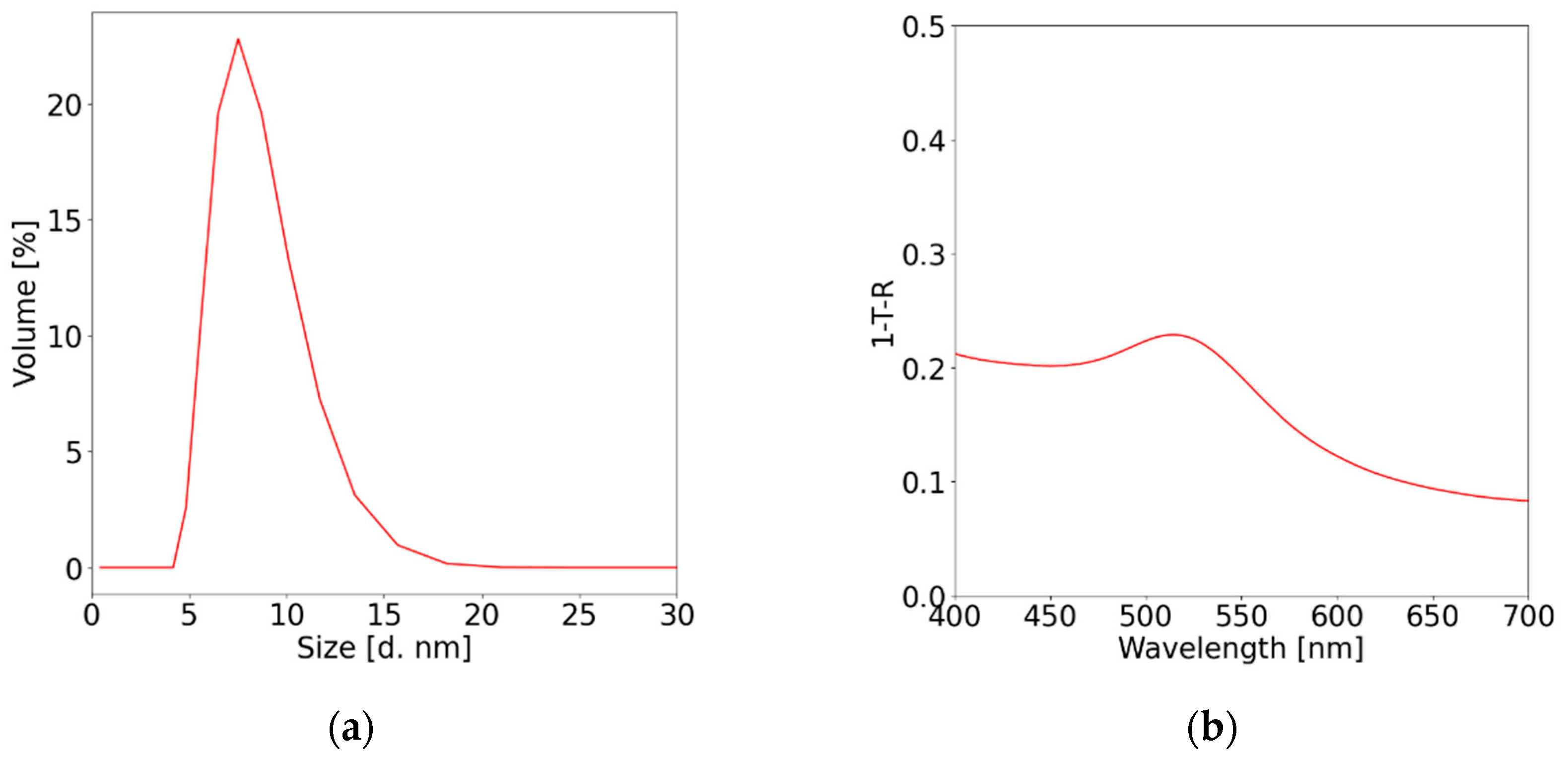
Figure 1(a) shows the DLS spectrum of the Au NPs. The average particle size was estimated to be 8 ± 2 nm. The Au NPs were monodispersed, as confirmed by the single peak in the DLS spectrum and the low polydispersity index (PDI) of about 0.26. The samples displayed a typical Au NPs localised surface plasmon resonance (LSPR) centred at 515 nm with an intraband absorption tail below 500 nm (Figure 1(b)) [16].
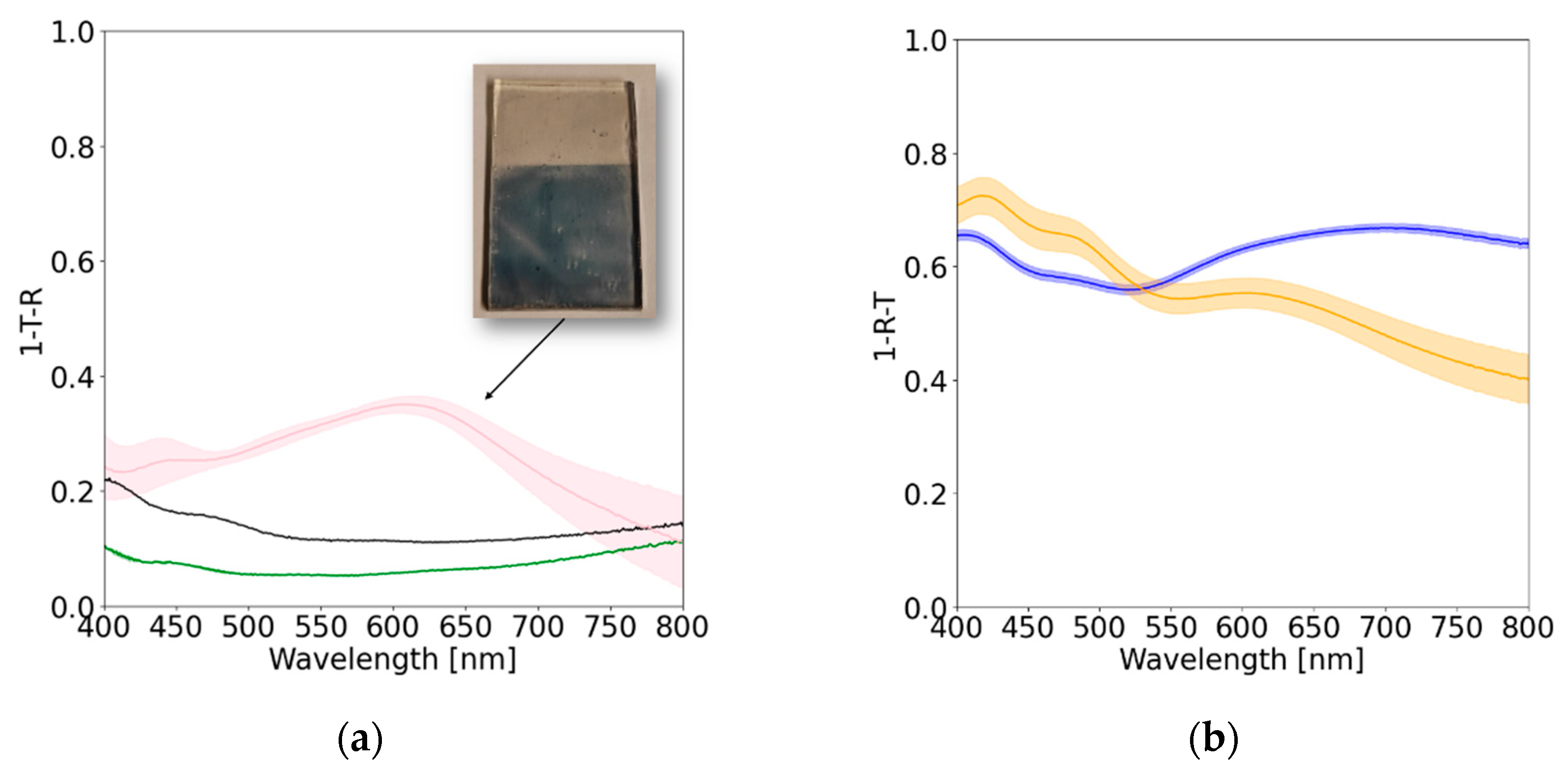
Figure 2 (a) shows the UV-Vis of the samples without a metallic film on top of FTO. Adding CuSCN to the FTO improved the transmission of the conductive glass by effectively reducing its reflectivity. The attachment of Au NPs to the CuSCN promoted by the 4-methoxythiophenol molecules is observed by the appearance of an absorption peak centred at 609 nm. The shift in the LSPR peak is explained by the change in the dielectric medium from water (εr ≈ 78 [26]) to CuSCN (εr ≈ 5.1 [27]), as seen with similar electrodes [28]. Note that without the Au metal film, the absorption across the visible range never exceeded 0.4.
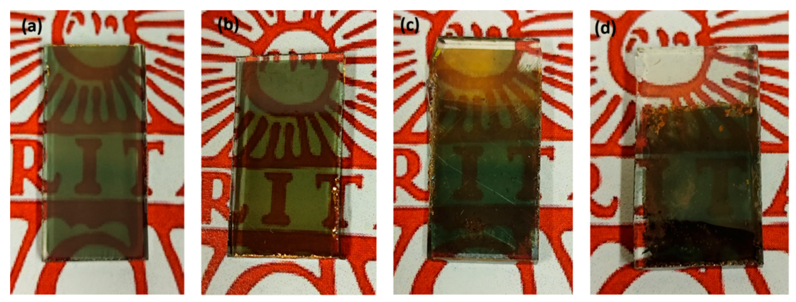
The addition of the 25 nm Au metal film significantly affected the electrode absorption, increasing the electrode absorption by about 0.5-0.6 (Figure 2(b)). This is noticeable when comparing the optical photographs of the films against a coloured background (Figure 3). However, when the Au film is on top of FTO and thus in an arrangement where the Fabry–Pérot nanocavity can occur, there is an apparent enhancement in the absorption between 550-800 nm. This increase in absorption cannot be justified by changes in film morphology because, according to AFM analysis (Figure 4), the films' roughness decreases as additional layers are added to the FTO but does not significantly affect the overall scattering [29]. All films with CuSCN were very smooth, considering they were fabricated on FTO, corroborating CuSCN properties to make thin and smooth films [25]. Therefore, the observed enhancement must be related to forming a Fabry–Pérot nanocavity, which enhances light absorption in some parts by as much as 20%. The observation is consistent with Shi et al. findings [22], where they observed the most significant optical absorption when the cavity modes overlap with the Au NPs LSPR absorption.
The finding demonstrates that Fabry–Pérot nanocavities can be created from bottom-up solution-based methods, even on semitransparent electrodes. Semitransparent electrodes enable optical spectroscopic measurements in transmission mode [30], energy transfer processes [31], and photochemical reactions with back-side illumination (the most common in academic settings) [32], making the proposed strategy highly relevant.
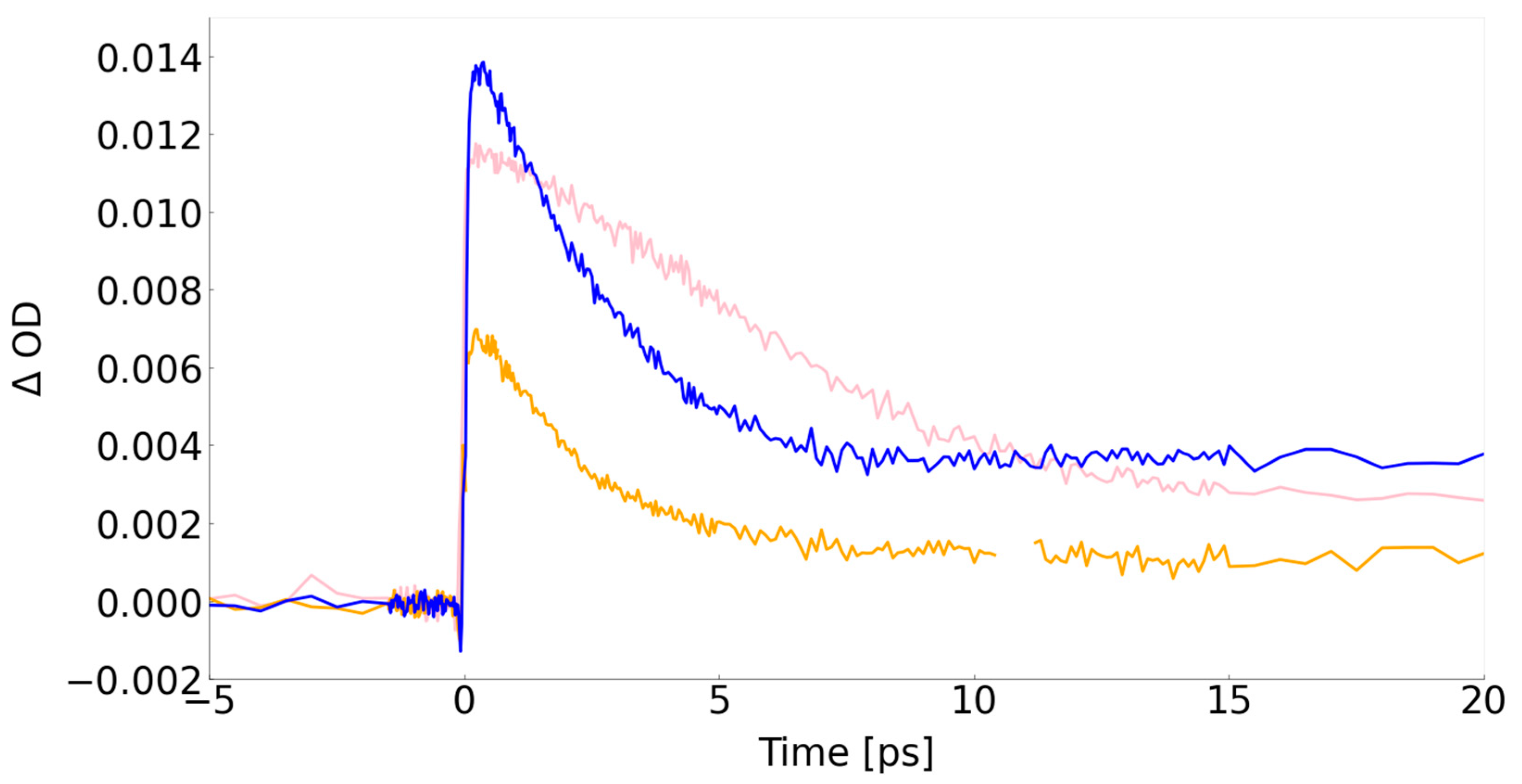
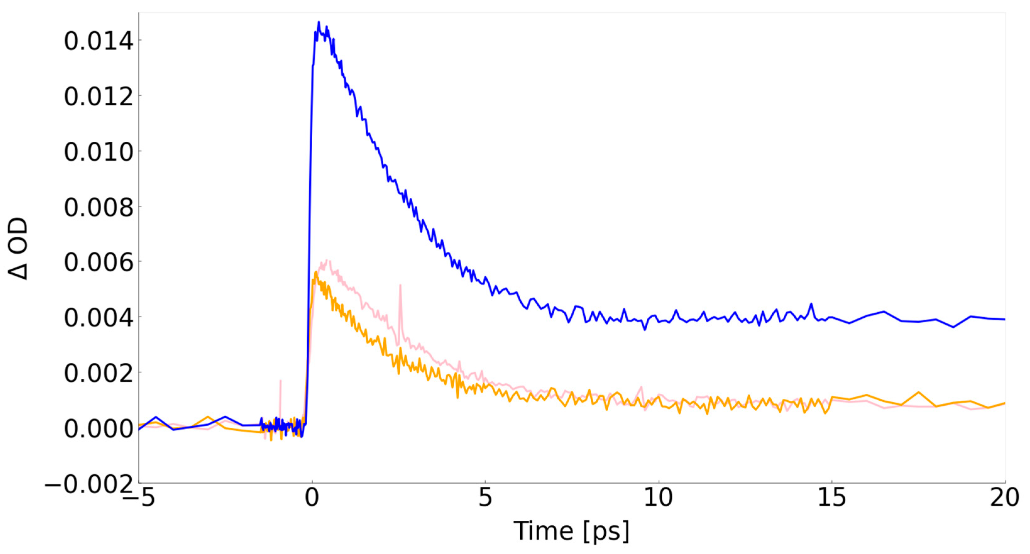
TAS measurements demonstrated the cavity's effectiveness in enhancing plasmon optical absorption and creating hot carriers. Optical excitation of the plasmon resonance results in the broadening of the optical absorption, forming a bleach signal around the excitation wavelength and two positive winglets on either side of the bleach signal [33,34,35,36]. Kinetic traces extracted at the maximum of the winglets or minimum of the bleach provide information on plasmon excitation efficiency (delta absorption (ΔOD) at time zero) and hot carriers' lifetime. The latter includes information about charge extraction from the plasmonic material in the presence of a suitable acceptor [36,37], in the present case, CuSCN.
Experiments were performed resonantly (excitation at 550 nm) and non-resonantly (excitation at 650 nm) with the Au NP LSPR peak. Three samples were measured, more specifically, FTO/Au NPs (reference sample), Au film/FTO/CuSCN/Au NPs (all components but no nanocavity) and FTO/Au film/CuSCN/Au NPs (with nanocavity). Note that the FTO/Au NPs (reference sample) has significantly more Au NPs because it is not limited by the Au NPs attachment to the CuSCN; therefore, one is to expect a high signal when exciting Au NPs resonantly. The outcome of the experiments is shown in Figure 5 and Figure 6.
Despite having considerably fewer Au NPs on the film, the ΔOD of the nanocavity sample (blue trace) at time zero is still slightly higher than the FTO/Au NPs. The enhancement is clearly due to the presence of the nanocavity because we have double the ΔOD compared with the Au film/FTO/CuSCN/Au NPs. This demonstrates that even under resonant excitation, the presence of the nanocavity significantly enhances the plasmonic effect, permitting similar optical absorptions with much less Au NPs density. The nanocavity effect becomes even more pronounced when performing non-resonant excitation (Figure 6). It is evident that under non-resonant excitation, the ΔOD at time zero for the FTO/ Au NPs drops significantly, while the signal for the sample with the nanocavity remains almost the same. This corroborates the optical measurements, demonstrating that the nanocavity expands the absorption range without changing nanoparticle morphology.
Analysis of the kinetic traces permits extraction of electron-phonon (e-ph) lifetime, which is sensitive to the amount of charge in the resonance, i.e., a decrease in e-ph lifetime signifies charge transfer to a suitable acceptor [36,37]. The motivation to use CuSCN was first to enable the fabrication of a Fabry–Pérot cavity using bottom-up solution methods. However, CuSCN is a known p-type semiconductor able to accept hot holes and thus create a photo-cathode device [38], which, to our knowledge, has not been demonstrated so far.
A summary of the e-ph lifetimes extracted from the fitting of the kinetic traces following the methodology proposed elsewhere [33,34,35] is presented in Table 1. The fittings show a significant decrease in the e-ph lifetime in the nanocavity when compared with Au on FTO glass. A reduction of e-ph lifetime is consistent with charge transfer from the plasmon to the semiconductor, which in the present case suggests hot hole transfer. A similar e-ph lifetime was observed when the sample was measured off-resonance from the Au NPs LSPR. Unfortunately, due to the low signal, the e-ph of the reference sample could not be determined. However, the e-ph lifetime is an intrinsic nanoparticle property; it is reasonable to assume that a similar level of hole extraction is attained when the sample is excited non-resonantly if fabricated into a nanocavity. The findings confirm that nanocavities can also be used to manufacture photo-cathodes, expanding the exciting portfolio.
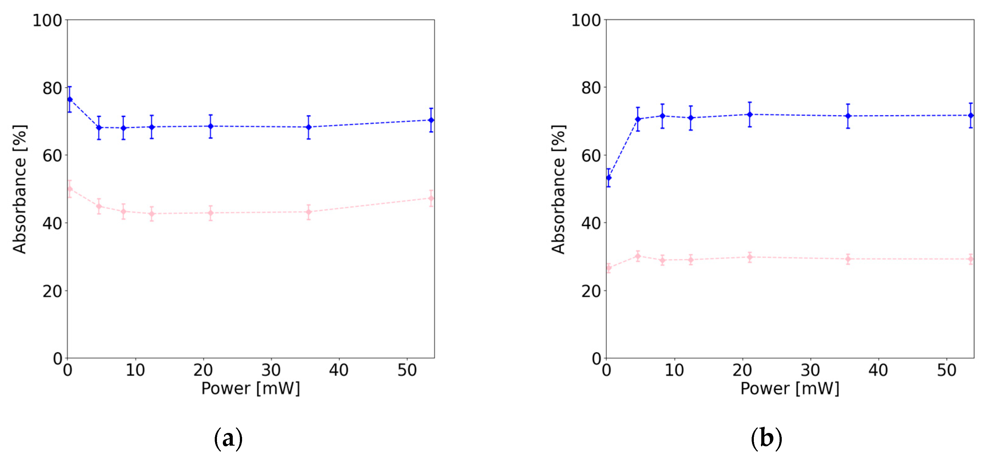
Power-dependent light absorbance measurements were carried out to substantiate the nanocavity optical properties further. Figure 7 shows the absorbance of the FTO/Au NPs sample (pink trace) and FTO/Au film/CuSCN/Au NPs (blue trace) under different CW laser power at resonant (excitation at 532 nm) and non-resonant excitation (excitation at 630 nm). Under resonant excitation (Figure 7(a)), the presence of the cavity led to an increase of about 20% in light absorption, which is significant if one considers that the FTO/Au NPs have a higher amount of Au NPs for the abovementioned reasons. When the experiments were performed using non-resonant excitation (Figure 7(b)), the enhancement was about 40%. Noticeably, the light uptake for the sample with the nanocavity did not change significantly between the two excitation modes, corroborating that the nanocavity expands the optical absorption range, as observed with the TAS experiments.
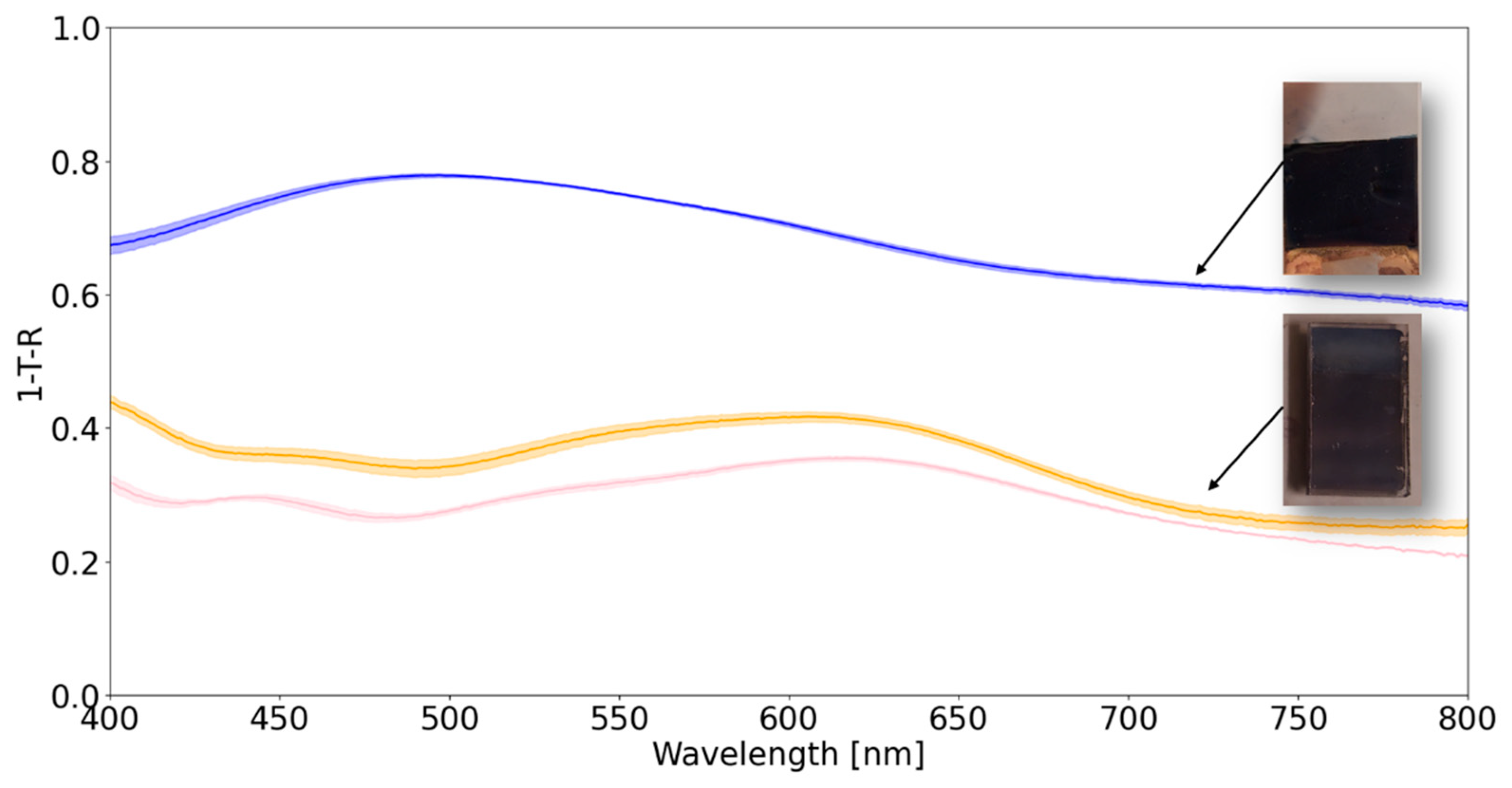
Shi et al. [22] optimised a nanocavity structure consisting of SiO2 glass/Au film {100 nm}/TiO2 {28 nm}/Au NPs {12 ± 5.5 nm} 14 nm inlaid into the TiO2. These opaque electrodes displayed a broad absorption across the visible range, with a dual absorption band. To demonstrate this could be achieved with the strategy proposed herein, nanocavities with the following architecture: FTO/Ag film {100 nm}/CuSCN {30 nm}/Au NPs {8 ± 2 nm} not inlaid were fabricated. By not inlaying the Au NPs in the semiconductor, one could reduce the workflow complexity while being conscious that that might affect the nanocavity efficacy in capturing the visible light [22]. Similar electrodes were fabricated for comparison purposes but with Ag film on the backside of the FTO. These electrodes provide information about electrode layers' combined absorption and the impact of dual absorption due to back-reflectance without the nanocavity effect. The outcome of the experiments is shown in Figure 8.
Adding the 100 nm Ag film to the electrode (backside of FTO) slightly improved the electrode's overall absorption. This is understandable since the Ag film back-reflects the light, enabling additional absorption by the Au NPs. When the Ag film was deposited on top of the FTO, a significant increase in absorption across the entire visible range was detected, which is noticeable in the optical photographs. The absorption increased by as much as 30% and displayed dual absorption bands, in agreement with Shi et al. [22] observations. They assigned the low energy absorption band to the cavity mode overlapping with the LSPR of the Au NPs, while the one at higher energy to the cavity mode attributed to the Au interband transition. The findings corroborate that the methodology can be adapted to opaque films, where the optical absorption gains are even more substantial in total absorption and absorption range.

4. Conclusions

A simple bottom-up method for manufacturing plasmonic Fabry-Pérot nanocavities is reported. Fabry-Pérot nanocavities are promising devices to broaden the absorption energy range of the plasmonic photosystems, enabling efficient capture of polychromatic light, such as sunlight. The fabrication method is solution-based, making it adaptable and able to leverage the breadth of plasmonic morphologies and materials available. The designs could be made for complete or partial light absorption, expanding the potential range of applications. The devices produced could be used as photo-cathodes since one could demonstrate that holes are transferred from Au to CuSCN.

Author Contributions

Conceptualization, S.K. and J.S.; methodology, S.K. and J.S.; formal analysis, S.K. and. J.S.; investigation, S.K., R.B.V. and V.R.S.; resources, J.S.; data curation, S.K. and J.S.; writing—original draft preparation, S.K. and J.S.; writing—review and editing, S.K. and J.S.; visualisation, S.K.; supervision, J.S.; project administration, S.K.; funding acquisition, J.S. All authors have read and agreed to the published version of the manuscript.

Funding

This research was funded by ÅForsk, grant number 23-268.

Data Availability Statement

The data supporting this study's findings are available from the corresponding author, [J.S.], upon reasonable request.

Acknowledgements

The authors thank Ms Keely-Marilyn Dodd-Clements for developing the protocol to attach the Au NPs to the CuSCN. The authors also thank Prof. Erik Johansson's group for providing access to the metal evaporator and Uppsala University for access to instrumentation.

Conflicts of Interest

The authors declare no conflict of interest.

References

  1. Brongersma, M. L.; Halas, N. J.; Nordlander, P. Plasmon-induced hot carrier science and technology. Nat. Nanotech. 2015, 10, 25–34. [Google Scholar] [CrossRef]
  2. Salamin, Y.; Ma, P; Baeuerle, B. ; Emboras, A.; Fedoryshyn, Y.; Heni, W.; Cheng, B’; Josten, A.; Leuthold, J. 100 GHz Plasmonic Photodetector. ACS Photon. 2018, 5, 3291–3295. [Google Scholar] [CrossRef]
  3. Zou, X.; Vadell, R. B.; Cai, B.; Geng, X.; Dey, A.; Liu, Y.; Gudmundsson, A.; Meng, J.; Sá, J. Ultrafast infrared-to-visible photon upconversion on plasmon/TiO2 solid films. J. Phys. Chem. Lett. 2023, 14, 6255–6262. [Google Scholar] [CrossRef]
  4. Brongersma, M. L. Plasmonic Photodetectors, Photovoltaics, and Hot-Electron Devices. Proc. IEEE 2016, 104, 2349–2361. [Google Scholar] [CrossRef]
  5. Vadell, R. B.; Zou, X.; Drillet, M.; Corvoysier, H.; Silveira, V. R.; Konezny, S. J.; Sá, J. Carrier dynamics in solution-processed CuI as a p-type semiconductor: the origin of negative photoconductivity. J. Phys. Chem. Lett. 2023, 14, 1007–1013. [Google Scholar] [CrossRef]
  6. Clavero, C. Plasmon-induced hot-electron generation at nanoparticle/ metal-oxide interfaces for photovoltaic and photocatalytic devices. Nat. Photon. 2014, 8, 95–103. [Google Scholar] [CrossRef]
  7. Geng, X.; Abdellah, M.; Vadell, R. B.; Folkenant, M.; Edvinsson, T.; Sá, J. Direct plasmonic solar cell efficiency dependence on spito-OMeTAD Li-TFSI content. Nanomaterials 2021, 11, 3329. [Google Scholar] [CrossRef] [PubMed]
  8. Mubeen, S.; Lee, J.; Singh, N.; Krämer, S.; Stucky, G. D.; Moskovits, M. An autonomous photosynthetic device in which all charge carriers derive from surface plasmons. Nat. Nanotech. 2013, 8, 247–251. [Google Scholar] [CrossRef] [PubMed]
  9. Linic, S.; Christopher, P.; Ingram, D. B. Plasmonic-metal nanostructures for efficient conversion of solar to chemical energy. Nat. Mater. 2011, 10, 911–921. [Google Scholar] [CrossRef] [PubMed]
  10. Mubeen, S.; Lee, J.; Singh, N.; Krämer, S.; Stucky, G. D.; Moskovits, M. An autonomous photosynthetic device in which all charge carriers derive from surface plasmons. Nat. Nanotech. 2013, 8, 247–251. [Google Scholar] [CrossRef] [PubMed]
  11. Oshikiri, T.; Ueno, K.; Misawa, H. Plasmon-induced ammonia synthesis through nitrogen photofixation with visible light irradiation. Angew. Chem. Int. Ed. 2014, 53, 9802–9805. [Google Scholar] [CrossRef]
  12. Zhang, N.; Han, C.; Fu, X.; Xu, Y. J. Funtion-oriented engineering of metal-based nanohybrids for photoredox catalysis: exerting plasmonic effect and beyond. Chem 2018, 4, 1832–1861. [Google Scholar] [CrossRef]
  13. . Vadell, R. B.; Sekar, P.; Patehebieke, Y.; Zou, X.; Kaul, N.; Broqvist, P.; Lindblad, R.; Lindblad, A.; Arkhypchuk, A.; Walletin, C.-J.; Sá, J. Single-Electron Transfer Reactions on Surface-Modified Gold Plasmons. Mater. Today Chem. 2023, 34, 101783. [Google Scholar] [CrossRef]
  14. Brongersma, M. L.; Shalaev, V. M. The Case for Plasmonics. Science 2010, 328, 440–441. [Google Scholar] [CrossRef]
  15. Coronado, E. A.; Encina, E. R.; Stefani, F. D. Optical properties of metallic nanoparticles: manipulating light, heat and forces at the nanoscale. Nanoscale 2011, 3, 4042–4059. [Google Scholar] [CrossRef] [PubMed]
  16. Hartland, G. V. Optical Studies of Dynamics in Noble Metal Nanostructures. Chem. Rev. 2011, 111, 3858–3887. [Google Scholar] [CrossRef] [PubMed]
  17. Douglas-Gallardo, O. A.; Berdakin, M.; Fauenheim, T.; Sánchez, C. G. Plasmon-induced hot-carrier generation differences in gold and silver nanoclusters. Nanoscale 2019, 11, 8604–8615. [Google Scholar] [CrossRef] [PubMed]
  18. Christ, A.; Tikhodeev, S. G.; Gippius, N. A.; Kuhl, J.; Giessen, H. Waveguide-plasmon polaritons: strong coupling of photonic and electronic resonances in a metallic photonic crystal slab. Phys. Rev. Lett. 2003, 91, 183901. [Google Scholar] [CrossRef] [PubMed]
  19. Pei, D.; Liang, E.; Cai, G.; Hu, W.; Fan, C.; Xue, Q. Dual-band perfect absorption and field enhancement by interaction between localized and propagating surface plasmons in optical metamaterials. J. Opt. 2011, 13, 075005. [Google Scholar] [CrossRef]
  20. Zeng, P.; Cadusch, J.; Chakraborty, D.; Smith, T. A.; Roberts, A.; Sader, J. E.; Davis, T. J.; Gómez, D. E. Photoinduced electron transfer in the strong coupling regime: waveguide-plasmon polaritons. Nano Lett. 2016, 16, 2651–2656. [Google Scholar] [CrossRef] [PubMed]
  21. Hägglund, C.; Zeltzer, G.; Ruiz, R.; Wangperawong, A.; Roelofs, K. E.; Bent, S. F. Strong coupling of plasmon and nanocavity modes for dual-band, near-perfect absorbers and ultrathin photovoltaics. ACS Photon. 2016, 3, 456–463. [Google Scholar] [CrossRef]
  22. Shi, X.; Ueno, K.; Oshikiri, T.; Sun, Q.; Sasaki, K.; Misawa, H. Enhanced water splitting under modal strong coupling conditions. Nat. Nanotech. 2018, 13, 953–958. [Google Scholar] [CrossRef]
  23. Pérot, A. & Fabry, C. On the Application of Interference Phenomena to the Solution of Various Problems of Spectroscopy and Metrology. Astrophys. J. 1899, 9, 87–115. [Google Scholar] [CrossRef]
  24. Piella, J.; Bastús, N. G.; Puntes, V. Size-Controlled Synthesis of Sub-10-nanometer Citrate-Stabilized Gold Nanoparticles and Related Optical Properties. Chem. Mater. 2016, 28, 1066–5463. [Google Scholar] [CrossRef]
  25. Wang, H.; Yu, Z.; Lai, J.; Song, X.; Yang, X.; Hagfeldt, A.; Sun, L. One plus one greater than two: high-performance inverted planar perovskite solar cells based on a composite CuI/CuSCN hole-transporting layer. J. Mater. Chem. A 2018, 6, 21435–21444. [Google Scholar] [CrossRef]
  26. Archer, D.G.; Wang, P. The Dielectric Constant of Water and Debye-Hückel Limiting Law Slopes. J. Phys. Chem. Ref. Data 1990, 19, 371–411. [Google Scholar] [CrossRef]
  27. Pattanasattayavong, P.; Mottram, A. D.; Yan, F.; Anthopoulos, T. D. Study of the Hole Transport Processes in Solution-Processed Layers of the Wide Bandgap Semiconductor Copper(I) Thiocyanate (CuSCN). Adv. Funct. Mater. 2015, 25, 6802–6813. [Google Scholar] [CrossRef]
  28. Hawe, P.; Silveira, V. R. R.; Vadell, R. B.; Lewin, E.; Sá, J. Plasmon-Mediated Oxidation Reaction on Au/p-Cu2O: The Origin of Hot Holes. Physchem 2021, 1, 163–175. [Google Scholar] [CrossRef]
  29. Collier, C. T.; Hesse, E.; Taylor, L.; Ulanowski, Z.; Penttilä, A.; Nousiainen, T. Effects of surface roughness with two scales on light scattering by hexagonal ice crystals large compared to the wavelength: DDA results. J. Quant. Spectrosc. Radiat. Transf. 2016, 182, 225–239. [Google Scholar] [CrossRef]
  30. Wu, F.; Finkelstein-Shapiro, D.; Wang, M.; Rosenkampff, I.; Yartsev, A.; Pascher, T.; Nguyen-Phan, T. C.; Cogdell, R.; Börjesson, K.; Pullerits, T. Optical cavity-mediated exciton dynamics in photosynthetic light harvesting 2 complexes. Nat. Commun. 2022, 13, 6864. [Google Scholar] [CrossRef]
  31. Wei, Y.-C.; Lee, M.-W.; Chou, P.-T.; Scholes, G. D.; Schatz, G. C.; Hsu, L.-Y. Can Nanocavities Significantly Enhance Resonance Energy Transfer in a Single Donor–Acceptor Pair? J. Phys. Chem. C 2021, 125, 18119–18128. [Google Scholar] [CrossRef]
  32. Silveira, V. R.; Vadell, R. B.; Sá, J. Photoelectrocatalytic conversion of nitrates to ammonia with plasmon hot-electrons. J. Phys. Chem. C 2023, 127, 5425–5431. [Google Scholar] [CrossRef]
  33. Link, S.; El-Sayed, M. A. Spectral Properties and Relaxation Dynamics of Surface Plasmon Electronic Oscillations in Gold and Silver Nanodots and Nanorods. J. Phys. Chem. B 1999, 103, 8410–8426. [Google Scholar] [CrossRef]
  34. Link, S.; Burda, C.; Wang, Z. L.; El-Sayed, M. A. Electron dynamics in gold and gold–silver alloy nanoparticles: The influence of a nonequilibrium electron distribution and the size dependence of the electron– phonon relaxation. J. Chem. Phys. 1999, 111, 1255–1264. [Google Scholar] [CrossRef]
  35. Link, S.; El-Sayed, M. A. Shape and size dependence of radiative, non-radiative and photothermal properties of gold nanocrystals. Int. Rev. Phys. Chem. B 2000, 19, 409–453. [Google Scholar] [CrossRef]
  36. Tagliabue, G.; DuChene, J. S.; Abdellah, M.; Habib, A.; Gosztola, D. J.; Hattori, Y.; Cheng, W.-H.; Zheng, K.; Canton, S. E.; Sundararaman, R.; Sá, J.; Atwater, H. A. Ultrafast Hot-Hole Injection Modifies Hot-Electron Dynamics in Au/p-GaN Heterostructures. Nat. Mater. 2020, 19, 1312–1318. [Google Scholar] [CrossRef] [PubMed]
  37. Ratchford, D. C.; Dunkelberger, A. D.; Vurgaftman, I.; Owrutsky, J. C. Quantification of efficient plasmonic hot-electron injection in gold nanoparticle-TiO2 films. Nano Lett. 2017, 17, 6047–6055. [Google Scholar] [CrossRef] [PubMed]
  38. Pattanasattayavong, P.; Promarak, V.; Anthopoulos, T. D. Electronic properties of Copper(I) Thiocyanate (CuSCN). Adv. Electron. Mater. 2017, 3, 1600378. [Google Scholar] [CrossRef]
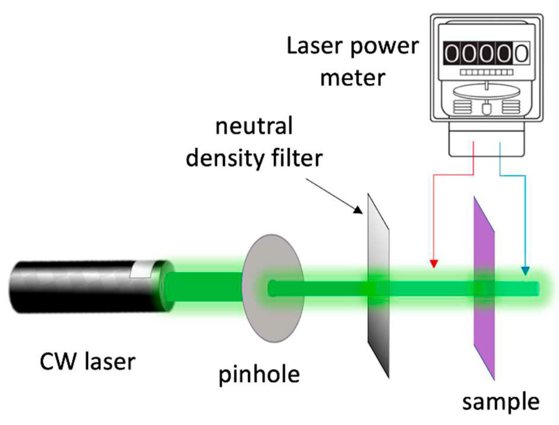
Scheme 1. Power-dependent light absorbance experimental setup.
Preprints 91560 sch001
Figure 1. Au NPs solution characterisation. (a) DLS spectrum (b) UV-vis spectrum.
Preprints 91560 g001
Figure 2. Electrodes optical absorption comparison. The trace shade represents the error originating from variability in sample fabrication. (a) UV-vis spectra of the FTO (black line), FTO/CuSCN (green line) and FTO/CuSCN/Au NPs (pink line). Insert it is the optical photograph of the FTO/CuSCN/Au NPs electrode. (b) UV-vis spectra of the transparent samples Au film/FTO/CuSCN/Au NPs (orange line) and FTO/Au film/CuSCN/Au NPs (blue line).
Preprints 91560 g002
Figure 3. Photos of the semitransparent electrodes. (a) FTO/Au film, (b) FTO/Au film/CuSCN, (c) Au film/FTO/CuSCN/Au NPs and (d) FTO/Au film/CuSCN/Au NPs.
Preprints 91560 g003
Figure 4. AFM images of the semitransparent electrodes. (a) FTO, (b) FTO/Au film, (c) FTO/Au film/CuSCN, and (d) FTO/Au film/CuSCN/Au NPs.
Preprints 91560 g004
Figure 5. TAS kinetic traces were extracted at the maximum of the winglet signal to the blue of the plasmonic transient bleach after excitation at 550 nm (resonant with Au NPs LSPR peak). FTO/Au NPs (pink trace), Au film/FTO/CuSCN/Au NPs (orange trace) and FTO/Au film/CuSCN/Au NPs (blue trace).
Preprints 91560 g005
Figure 6. TAS kinetic traces were extracted at the maximum of the winglet signal to the blue of the plasmonic transient bleach after excitation at 650 nm (non-resonant with the Au NPs LSPR peak). FTO/Au NPs (pink trace), Au film/FTO/CuSCN/Au NPs (orange trace) and FTO/Au film/CuSCN/Au NPs (blue trace).
Preprints 91560 g006
Figure 7. Power-dependent light absorbance for the FTO/Au NPs sample (pink trace) and FTO/Au film/CuSCN/Au NPs (blue trace): (a) employing the 532 nm CW laser (resonant excitation); and (b) employing the 630 nm CW laser (non-resonant excitation).
Preprints 91560 g007
Figure 8. UV-vis spectra of the non-transparent samples with reflective metallic film (100 nm Ag). FTO/CuSCN/Au NPs (pink line), Ag film/FTO/CuSCN/Au NPs (orange line) and FTO/Ag film/CuSCN/Au NPs (blue line) with the respective optical photos of the samples.
Preprints 91560 g008
Table 1. Summary of the e-ph lifetimes extracted from the TAS kinetic traces.
Sample Resonant excitation
(ps)
Non-resonant excitation
(ps)
FTO/Au NPs 4.0 ± 0.1 --[1]
FTO/Au film/CuSCN/Au NPs 2.2 ± 0.1 2.3 ± 0.1
[1] Too weak absorption at 650 nm, making it challenging to determine the value accurately.
Disclaimer/Publisher’s Note: The statements, opinions and data contained in all publications are solely those of the individual author(s) and contributor(s) and not of MDPI and/or the editor(s). MDPI and/or the editor(s) disclaim responsibility for any injury to people or property resulting from any ideas, methods, instructions or products referred to in the content.
Copyright: This open access article is published under a Creative Commons CC BY 4.0 license, which permit the free download, distribution, and reuse, provided that the author and preprint are cited in any reuse.
Prerpints.org logo

Preprints.org is a free preprint server supported by MDPI in Basel, Switzerland.

Subscribe

© 2024 MDPI (Basel, Switzerland) unless otherwise stated