Preprint
Article

Bubble Wrap-Like Carbon-Coated Rattle-Type Silica@silicon Nanoparticles by Surface-Protected Etching as Hybrid Anodes for Lithium–Ion Batteries

Altmetrics

Downloads

131

Views

71

Comments

0

A peer-reviewed article of this preprint also exists.

Submitted:

28 November 2023

Posted:

28 November 2023

You are already at the latest version

Alerts
Abstract
The severe volumetric expansion of silicon nanoparticles (~400 %) limits their practical application as an anode material for next-generation lithium–ion battery (LIB). Here, we describe the fabrication and characterization of conformal polydopamine carbon shell encapsulating rattle-type silica@silicon nanoparticles (PDA−PEI@PVP−SiO2@Si) with tunable void structure prepared following a dual SiO2 template using (3–aminopropyl)triethoxysilane (APTES) as a self-catalytic, structure-directing agent to tetraethyl orthosilicate (TEOS) pretreated with polyvinylpyrrolidone (PVP K30) via modified Stöber process. Polyethylene imine (PEI) crosslinking facilitated the construction of interconnected three-dimensional bubble wrap-like carbon matrix structure through hydrothermal treatment, pyrolysis, and subsequent surface-protected etching. The composite anode material delivered 539 mAh·g−1 capacity after 100 cycles at 0.1 A·g−1, and 453 mAh·g−1 rate performance at 5 A·g−1. The satisfactory electrochemical performance of the PDA−PEI@PVP−SiO2@Si was attributed to the following: the rattle-type structure providing void space for Si volume expansion, PVP K30-pretreated APTES/TEOS SiO2 seeds via catalyst-free, hydrothermal-assisted Stöber protecting Si/C spheres upon etching, carbon coating strategy increasing Si conductivity while stabilizing the solid electrolyte interface (SEI), and PEI carbon crosslinks providing continuous conductive pathways across the electrode structure. The present work realizes a promising strategy to synthesize the tunable yolk–shell C@void@Si composite anode materials for high power/energy-density LIB applications.
Keywords: 
Subject: Chemistry and Materials Science  -   Nanotechnology

1. Introduction

Global environmental key issues stemming from elevated greenhouse gasses, especially carbon dioxide, induced climate change and its adverse effects triggering species endangerment, and ozone depletion, including catastrophic effects to biodiversity, pose a significant threat to human survival at a highly alarming rate [1]. International treaties, such as the Paris Agreement [2], and international federations, such as the United Nations (UN) and European Union (EU), have adopted tactical approaches to regulate and promote the transition from a fossil fuel reliant economy to a carbon neutral economy to mitigate climate change [3,4]. In 2022, 91 % of energy generation continues to rely on fossil fuel, while CO2 emission from the transportation sector grew to approximately 8 Gt CO2, 3 % higher than in 2021 emission. To achieve the Net Zero Emission (NZE) scenario in the transportation sector by 2050, global environmental policies focused on enabling low- and zero-emission vehicle operations and promoting transportation de-carbonization are intensifying [5]. Major economies have adopted lithium–ion battery (LIB) technology for the electrification of road vehicles, with electric vehicles (EV) continuing to gain momentum starting from 2022; however, the mismatch between supply demands for critical materials for such advanced applications presents an apparent material scarcity [6].
Due to its simplified cell chemistry, LIB technology has been the dominating technology powering most commercial electronic devices [7,8]. Moreover, the LIB system operates within wide range operating voltages with minimal self-discharge and memory defects, with low maintenance requirements [9]. Despite high structural stability, current graphite anodes with only 372 mAh·g−1 of gravimetric capacity used in commercial LIB have long been regarded as unsuitable for high-energy and high-energy density applications, such as in EV and grid scale operations [10]. The search for new battery materials capable of delivering both high energy density and other desirable features, such as fast charging functions [11], longer driving range on a single charge [12], relatively less expensive active materials with reduced amounts of critical metals, such as nickel (Ni) and lithium (Li) [13], battery stability, even in extreme temperature conditions [14], and in general, longer battery life, are key factors that battery manufacturers need to consider during material selection. These critical conditions must all be satisfied to successfully transition into pure electric or hybrid electric vehicles.
Since the current LIB technology requires a dramatic boost in specific capacity for advanced EV applications, the use of silicon (Si) as an alternative to graphite has been widely investigated. Aside from the obvious advantage of excellent theoretical capacity (4,200 mAh·g−1 for Li22Si5), Si operates within a moderate onset voltage potential of (0.3 − 0.4) V above Li/Li+, hence minimizing the occurrence of undesirable Li plating side reactions [15,16,17]. Being the second most abundant element in the Earth’s crust after oxygen, coupled with environment-friendliness, Si as an active anode material presents great potential to power EVs, offering lower production costs that are advantageous for market values [18,19]. Aside from the cheap cost of Si due to its natural abundance partnered with the high theoretical capacity expected to improve driving range, its fast-charging capability and stable cycling performance in extremely low temperature conditions mean that it offers great potential for powering future LIB applications [20].
However, when used in pristine conditions, Si tends to undergo repetitive volumetric expansion, triggering the formation of a mechanically unstable solid electrolyte interface (SEI) layer. Continuous volume expansion and contraction of the Si morphology exposes more bare Si particles that are vulnerable to electrolyte decomposition, excessively consuming finite Li+ ions in the process, forming a thicker SEI film, eventually deteriorating reversible capacity, and further drying the entire cell [21,22]. In addition, issues regarding the inferior electronic conductivity of Si (Si 10−3 S·cm−1) compared to graphite and activated carbons (C 1 S·cm−1), the severe Si particle aggregation due to high surface energy, and the native oxide layer of the as-received Si that adds to the challenge of dispersion stability, often lead to the uneven distribution of active materials within the anode structure. This triggers particle isolation, crack formation, and pulverization during prolonged lithiation/delithiation cycles [23].
Various morphologies of Si ranging from nanostructuring into nanoparticle [24], nanowires [25], nanotubes [26], nanospheres [27], and nanoporous structures [28] to 3D microstructures [29] have been explored, and techniques to enhance the electrochemical performances of Si have been developed. For example, our group has incorporated diverse carbon nanomaterials, such as carbon nanofibers [31,32], carbon nanotubes [33,34], graphene [35,36], and graphene quantum dots [34,37] to improve the electronic conductivity of Si, while offering protection against parasitic electrolyte decomposition reactions and detrimental volume changes. While the use of highly functional carbon nanomaterials seems promising, high-temperature thermal processing [38], costly precursor materials [39,40], low material yield [41], and exhaustive synthetic routes requiring multiple organic reactions and purifications at intermediate steps [42,43] continue to present major barriers for EV applications. There is an urgent need for battery manufacturers and their subsidiaries to develop a low-cost yet efficient synthetic route to manufacture LIBs with advanced features for EV applications that maximize the advantageous features of Si, while considering methods to address its severe volume expansion and low conductivity.
As upon cycling, Si tends to repeatedly expand and contract, a straightforward synthetic approach of incorporating a hollow, void space between Si and the carbon coating layer, as reported in particular in Si/SiOx hybrids [44], 3D−Si@SiOx/C [45], and yolk–shell structured Si/C nanocomposite anodes [46], has exhibited interesting improvements in terms of stability and electrochemical performance that are attributed to the extra void space that is capable of absorbing internal Si volume changes. The use of hard templates, such as silica (SiO2) [47], typically synthesized via a Stöber route [48], which involves the hydrolysis and condensation reaction of silicon alkoxides (e.g., tetraethyl orthosilicate (TEOS)) in an alcohol solvent (e.g., ethyl alcohol (EtOH)) in the presence of water and a base catalyst (e.g., ammonia) [49], have been widely used to fabricate yolk–shell structures. Removing the SiO2 patterning substrate to achieve yolk–shell structure will require either a reactive ion etching (RIE) process [50], or a solution-phase chemical etching using either a strong acid (e.g., (45−48) % hydrofluoric acid (HF) or in diluted form, as in buffered HF (BHF)) [51], sometimes in combination with inorganic fluorides (e.g., sodium fluoride (NaF) and ammonium fluoride (NH4F)), as in a buffered oxide etch (BOE) [52], or the use of high concentrations of a strong base (e.g., sodium hydroxide (NaOH) at boiling temperatures [53].
Despite the simplicity of the SiO2 coating process via the Stöber route, challenges are presented that are related to the utilization of SiO2 hard template and safety concerns of the handling of highly corrosive and highly toxic HF during template removal. First, the tunability of the HF-assisted chemical etching of SiO2 is extremely challenging, due to high etching rates, even at dilute concentrations (1,000 Å·min−1 in industry-standard 10:1 BHF) [54]. Second, using TEOS as a SiO2 precursor has been reported to produce a continuous, dense, and rigid SiO2 coating to Si that is susceptible to mechanical stress during cycling [55]. Third, although techniques, such as the surface-protected etching initially reported by Zhang et al., have demonstrated significant improvement to the tunability of etching SiO2 shells by coating poly(vinylpyrrolidone) (PVP K15) polymers [56], it should be noted that the numerous refluxes of SiO2 hydrolysis, followed by the subsequent PVP surface protection required to employ such protected etching, suggests a tedious synthetic process [57]. Therefore, the utilization of an alternative longer PVP K30 chain with greater molecular mass to improve the stability of polymer chains protecting SiO2 shells in a simplified, one-pot technique provides a promising alternative strategy to improve harsh etching conditions, and therefore prevent the total dissolution of Si active materials in yolk–shell Si/C composites.
This paper describes the fabrication of polydopamine (PDA)-coated and poly(ethyleneimine) (PEI)-crosslinked rattle-type SiO2@Si nanoparticles prepared using a dual template strategy using TEOS and (3-aminopropyl)triethoxysilane (APTES) pretreated with PVP K30 as a SiO2 sacrificial template via a hydrothermally-assisted Stöber process, followed by subsequent carbonization by pyrolysis and surface-protected NaOH etching. To evaluate the design of a yolk–shell structure, a composite material prepared with the same process was fabricated with core–shell structure. The fabricated hybrid composites were employed as an anode material for the LIB, and the electrochemical performances were evaluated. The representative yolk–shell composite material (PDA−PEI@PVP−SiO2@Si) delivered an initial capacity of 719 mAh·g−1, and maintained 539 mAh·g−1 after 100 cycles at 0.1 A·g−1. At 5 A·g−1, 453 mAh·g−1 of capacity was sustained, which was relatively higher, compared to its core–shell composite counterparts.

2. Materials and Methods

2.1. Materials and Reagents

The reagents employed in the study were of analytical grade, and were used as obtained, with no further purification. Sulfuric acid (H2SO4, 98.0 %), hydrogen peroxide (H2O2, 30.0 %), and PVP K30 were obtained from Daejung Chemical & Metals. The Si nanoparticles (powder, APS ≤ 50 nm, 98.0 %) were purchased from Alfa Aesar. TEOS (≥ 99.0 %), dopamine hydrochloride for PDA coating (C8H12ClNO2), and PEI solution (MW ~ 750,000; 50 wt.% in H2O) were purchased from Sigma–Aldrich. APTES (≥ 99.0 %) was purchased from AcroSeal, Thermo Scientific Chemicals. EtOH (C2H5OH, 94.5 %) was purchased from Samchun Pure Chemical Co., Ltd. NaOH was supplied by Duksan Pure Chemicals. The high-purity industrial argon (Ar, 99.0 %) gas used for pyrolysis was supplied by PSG Corp, Korea. All aqueous solutions were prepared and washed with deionized (DI) water.

2.2. Fabrication of Yolk–Shell and Core–Shell PDA−PEI@PVP−SiO2@Si Composites

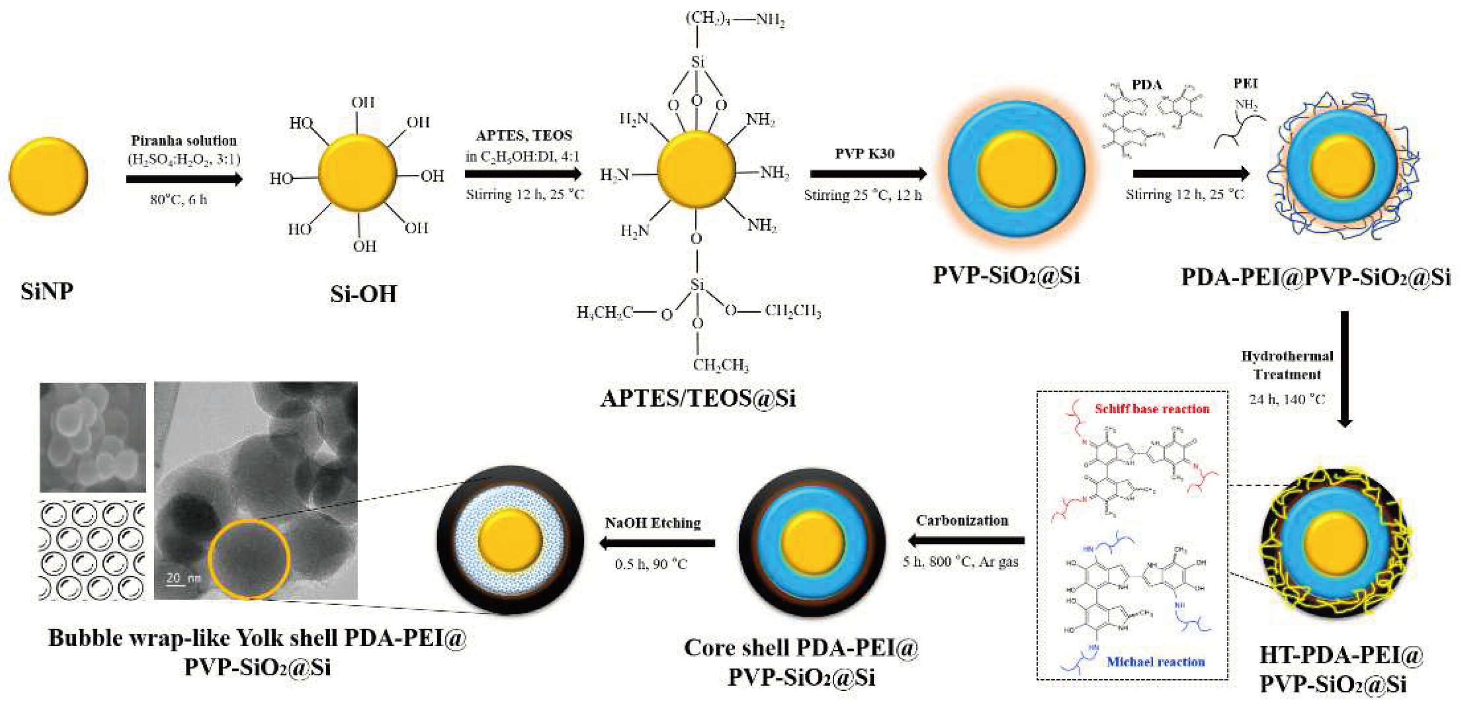
Figure 1 illustrates the one-pot hydrothermal synthesis of yolk–shell composite materials via the Stöber process. The fabrication process is described as follows. The hydrophilicity of the as-received Si nanoparticles was increased following a typical piranha solution pre-treatment, which made available abundant surface −OH groups to Si (Si–OH), described in previous work of our group [37].
The piranha pre-treated Si–OH (0.5 g) was dispersed in EtOH (480 mL) mixed with DI (120 mL) solution via sonication for 2 h. After cooling, TEOS (7 mL) and APTES (2 mL) were added in succession to the dispersed Si–OH solution in a drop-wise manner (~0.5 mL·min−1) under rigorous stirring (300 rpm), to prevent aggregation. PVP K30 (0.5 g) was dissolved in DI (10 mL), before adding to the solution. The solution was mechanically stirred at room temperature (RT) overnight to ensure the completion of hydrolysis and condensation reactions. Afterwards, PDA (0.5 g) and PEI solution (2.5 mL) were successively added to the solution, and further kept overnight under constant stirring, until a viscous solution was observed. To obtain SiO2 shells with uniform size, facilitate PVP K30 loading into SiO2 shells, and enhance PDA−PEI carbon coating, the resultant solution was transferred into a Teflon-lined container, and reacted for 24 h at 140 °C. After the hydrothermal treatment, the products were collected via filtration with washing with large amounts of EtOH and DI, and subsequent overnight drying in a vacuum oven at 80 °C. Carbonization of polymer coatings was carried out by pyrolysis in a tube furnace at 800 °C for 5 h in Ar gas.
At this stage, core–shell PDA−PEI@PVP−SiO2@Si composite was collected after the pyrolysis. Meanwhile, representative yolk–shell PDA−PEI@PVP−SiO2@Si composite was obtained after an additional chemical etching process using NaOH (2.5 M) were carried out at 90 °C, followed by DI washing and collected as a black powder by oven-drying overnight at 80 °C. To elucidate the effect of adding APTES in SiO2 synthesis, yolk–shell and core–shell composite materials with only TEOS-derived SiO2 shells were alternatively fabricated (PDA−PEI@−TEOS@Si). Similarly, a PEI-free composite material (PDA@PVP−SiO2@Si) was also synthesized to further study the PDA−PEI coating efficiency, while the effect of surface-protected etching was elucidated by fabricating SiO2 shells without PVP K30 (PDA−PEI@SiO2@Si). Finally, the effect of hydrothermal treatment (HT−PDA−PEI@PVP−SiO2@Si) in the overall composite fabrication was studied against composites obtained via the traditional Stöber process and carbon coating performed at RT (RT−PDA−PEI@PVP−SiO2@Si).

2.3. Materials Characterization

The structural and morphological characteristics of the fabricated composites were examined by field-emission scanning electron microscopy (FE−SEM, S-4800, Hitachi, Tokyo, Japan) at 100 kV, while the high-resolution transmission electron microscopy provided insights into the internal yolk–shell structures (TEM, JEM-2100, JEOL, Tokyo, Japan). Energy dispersive X-ray (EDS, ARL-3460, Thermo Fischer Scientific, Waltham, MA, USA) mapping was used to determine qualitative and quantitative microanalyses of the elements in the sample composites. The crystalline compositions were characterized using powder X-ray diffraction (XRD) measurements using CuKα radiation (K = 1.5418 Å) at 2ϴ = (2−90 in a 2 kW Ultima IV (Rigaku, Tokyo, Japan) instrument. Raman spectra were obtained within (500−3,000) cm1 wavelength using a Jobin–Yvon LabRAM HR-800 (Horiba, Kyoto, Japan) with laser light irradiation (λ = 514 nm). Fourier-transform infrared spectroscopy (FTIR) analysis was conducted within the (400−4,000) cm1 frequency range, using potassium bromide (KBr) pellets on a Nicolet 6700 spectrophotometer (Thermo Fischer Scientific, Waltham, MA, USA). Al–Kα twin-anode X-ray photoelectron spectroscopy (XPS, Multilab-2000, Thermo Fischer Scientific, Waltham, MA, USA) was used to evaluate the chemical bonding states in the composite materials. The mass loadings of Si, SiOx, and carbonaceous materials present in the composites samples were extrapolated from thermogravimetric analysis (TGA) coupled with differential thermal analysis (DTA), and the derivative thermogravimetric (DTG) curves in percent mass loss per degree Celsius) were collected using a Diamond TG/DTA system (PerkinElmer, Waltham, MA, USA) from (20−900) °C at a heating rate of 10 °C·min1 in a nitrogen-protected environment, to prevent the rapid oxidation of Si into SiO2.

2.4. Electrochemical Testing

The fabricated yolk–shell and core–shell composites were used as an active anode material in a two-electrode battery system. To evaluate the electrochemical performance of the resultant composite materials, a conventional slurry mixture was obtained by mechanically mixing 80 wt.% of the active composite materials with 10 wt.% of binder and 10 wt.% of Super P as a conductive agent cast on a copper (Cu) foil as the current collector. Circular disks of 14 mm diameter were punched from the electrode plate with ~1 mg·cm−2 average load density to obtain working electrodes from the fabricated core–shell and yolk–shell composites. Depending on the coating efficiency of the slurry mixture onto the electrode plate after vacuum drying at 80 °C for 24 h, carboxymethyl cellulose (CMC) binder in DI water solvent and polyvinylidene fluoride (PVDF) dissolved in N–Methyl-2-pyrrolidone (NMP) organic solvent were employed as the binder material during slurry preparation.
Coin-type cells (2032) were assembled inside an Ar-filled glove box using the working electrodes from the fabricated composites, a metal Li foil as the counter/reference electrode, and a standard polyethylene membrane (Celgard 2600) as the separator soaked in the electrolyte. The electrolyte employed was 1.0 M of LiPF6 in 3:7 w/w ethylene carbonate (EC) / ethyl methyl carbonate (EMC) with 7 wt.% of fluoroethylene carbonate (FEC) to increase the solvation and improve cycling stability. Cycling voltammetry (CV) conducted at a scan rate of 0.1 mV·s−1 at voltages of (0.01 − 1.5) V at 25 °C and electrochemical impedance spectroscopy (EIS) measurements at frequencies of (100 kHz to 10 mHz) and amplitude of 5 mV were conducted on a Chi 660F electrochemical analysis instrument (CH Instruments, Inc. Shanghai, China). Cycling test, high-rate loading tests and galvanostatic charge/discharge profile measurements were performed using a battery tester (Neware Co., Ltd. Shenzhen, China) at voltages of (0.01 − 1.5) V (vs. Li/Li+). The specific capacity was computed based on the mass loading of the anode material in the working electrode disks.

3. Results and Discussion

3.1. Role of APTES in the Synthesis of SiO2@Si Shells

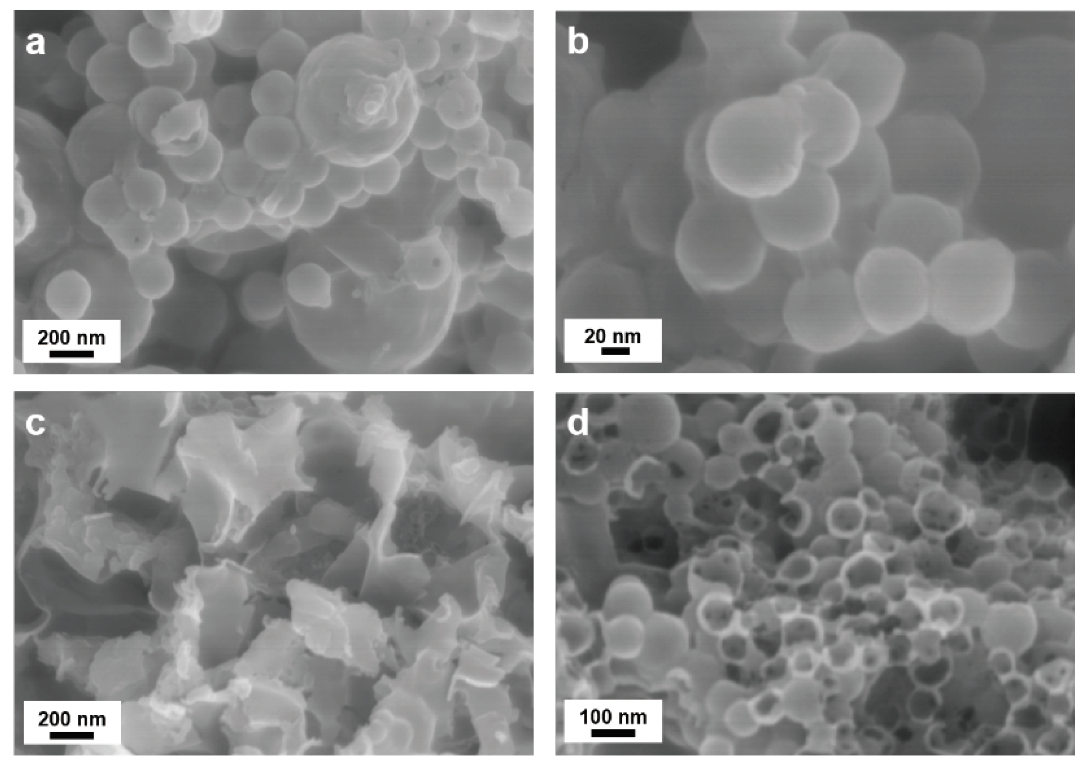
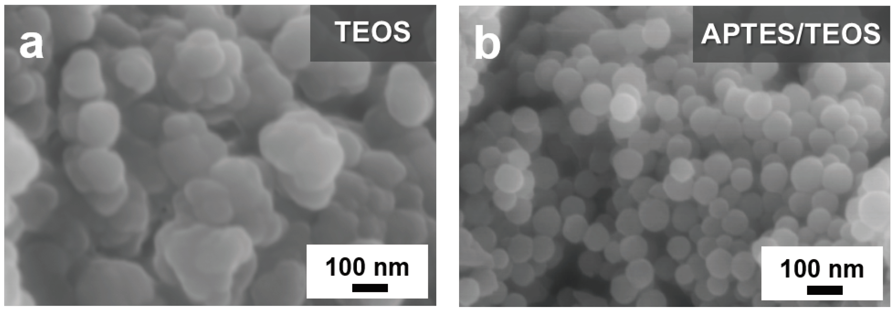
Figure 2 compares the SEM images of the TEOS- and APTES/TEOS-derived SiO2 shells precursors:
Figure S1 of the Supplementary Information (SI) presents the FE−SEM image and the FT−IR spectra of Si into Si–OH after the piranha pre-treatment. A thick and uneven coating from the TEOS-derived SiO2 shell can be observed in Figure 2a. In contrast, the APTES/TEOS-derived SiO2 presented in Figure 2b exhibits a relatively more uniform SiO2 coating, with less agglomeration of Si–OH nanoparticles. Additionally, a conformal spherical morphology can be observed with particle average diameter of approximately 60 nm. This result is attributed to the self-catalytic activity of APTES regarding the sol–gel SiO2 particle formation, wherein the formation of siloxane bonds with the abundant silanol groups of Si–OH takes place, even without the presence of an alkali catalyst [55].
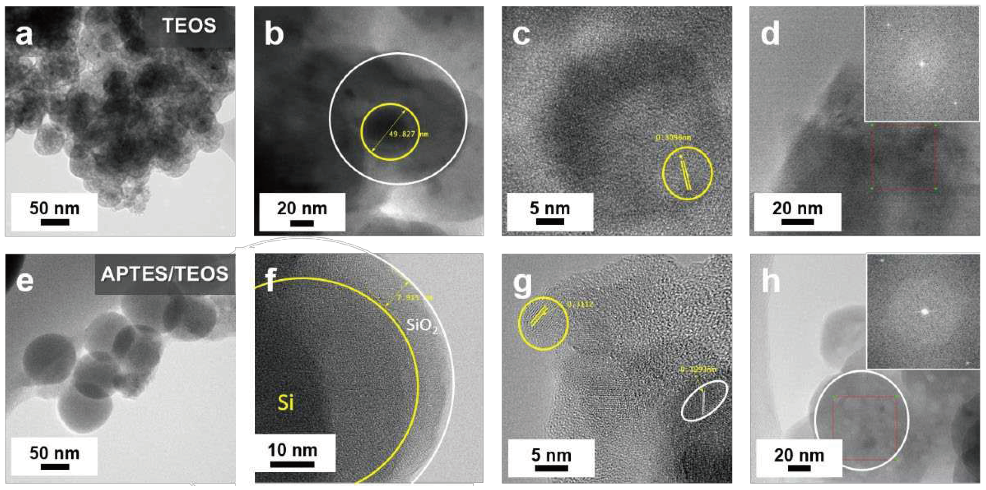
Evidence supporting the self-catalyzing role of APTES in facilitating SiO2 growth and the successful coating on Si–OH is further supplied by the TEM results of Figure 3. Notable particle agglomeration of the TEOS−SiO2@Si with no structural organization can be observed in Figure 3a. An isolated TEOS−SiO2@Si particle shown in Figure 3b portrays an approximately 50 nm Si nanoparticle encircled by a thick SiO2 coating with evident aggregation characterized by dark patches scattered in the background. The in-plane lattice fringe highlighted in Figure 3c reveals a 0.3096 nm ordered lattice spacing, which is attributed to the (111) plane of Si [37]. The inset in Figure 3d shows that after the SiO2 sol–gel coating process using TEOS, a corresponding fast Fourier transform (FFT) pattern verified Si crystallinity was sustained.
On the other hand, the role of APTES as a structure-directing agent is highlighted in Figure 3e, which depicts the APTES/TEOS-derived SiO2@Si with no visible aggregation of particles, and with uniform spherical morphology. A thin, conformal SiO2 coating (~8 nm) was observed in an isolated APTES/TEOS−SiO2@Si nanoparticle shown in Figure 3f. Two distinct crystal lattice spacings were detected in Figure 3g, namely (0.3112 and 0.1993) nm, in good agreement with the (111) and (220) planes, respectively, of Si [31,37]. Notable bright spots are shown in the inset image in Figure 3h, indicating that the inherent crystallinity of Si is maintained.
Previous literature citing the co-condensation of TEOS and APTES in EtOH and DI have generally incorporated APTES as a surface-modifier in a post-modification or grafting of amino groups to Si [35], as a precursor material to SiO2 [55], such as in soft-hard template strategies [47], often with other surfactants (e.g., cetyl trimethyl ammonium bromide, CTAB) [58]. Figure S2 of the SI illustrates the crucial role of APTES as a self-catalytic, structure-directing agent to TEOS, the hydrolysis and condensation reaction mechanism, and the formation of siloxane networks from APTES and TEOS. Note that although the pristine Si nanoparticles inherently possess a native oxide layer due to inevitable surface oxidation during manufacturing, pre-treatment with piranha solution is generally preferred to optimize the number of surface hydroxyl groups to form bonds with the silanol groups of APTES and TEOS. The −OH groups of piranha-pre-treated Si–OH energetically favored the formation of siloxane bonds in a condensation reaction, resulting in a well-ordered silane layer on the surface of Si in the APTES/TEOS, even without the presence of an alkali catalyst.
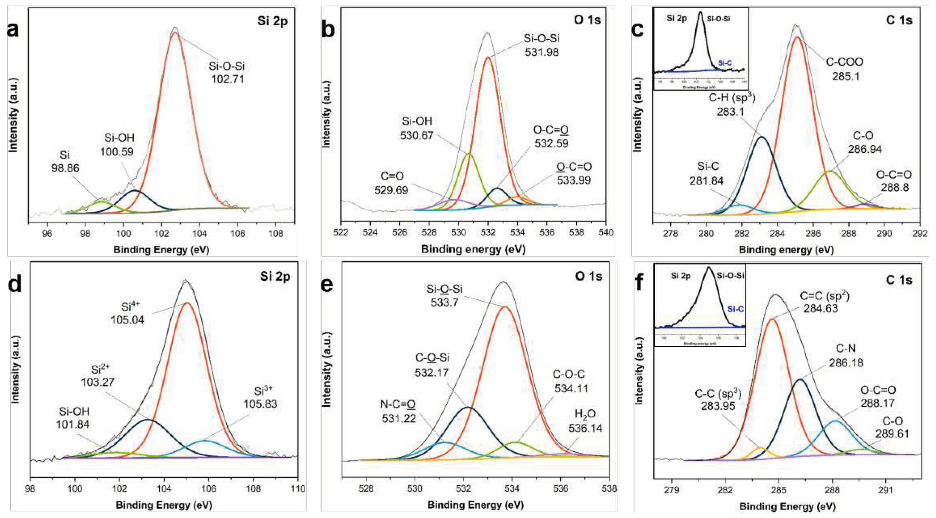
Figure 4 shows the results of XPS analysis conducted to confirm the changes in the elemental composition during SiO2 synthesis from the two precursors, and subsequent coating with Si nanoparticles. The high-resolution Si 2p spectra of the TEOS-derived SiO2@Si in Figure 4a reveals three peaks at 102.71 eV that are attributed to the Si–O–Si band, 100.59 eV related to Si–OH, and a small peak at 98.86 eV corresponding to Si. These peaks also appear in the O 1s scan in Figure 4b, revealing peaks at 531.98 eV for the Si–O–Si and 530.67 eV for the Si–OH [59]. The high relative intensities of the Si–O–Si peak at both Si 2p and O 1s scans suggest that the majority of the TEOS silane precursor was successfully converted into SiO2. The trace amounts of Si–OH are assumed to be from the unreacted hydroxyl groups from piranha pre-treatment. The occurrence of a small Si peak suggests that the SiO2 coating derived from TEOS precursor resulted in inefficient coating, with bare Si nanoparticles remaining. The C 1s spectra in Figure 4c reveal peaks corresponding to the different chemical environments of carbon within the organic groups of TEOS: 283.1 for sp3 C−C, 285.1 eV for the C−COO sub-peak due to the chemical shift of the carbon bonded to an adjacent ester group, the ester group C−O at 286.94 eV, and the ester group sub-peak O−C=O at 288.8 eV, and Si–C peak at 281.84 eV. Furthermore, C 1s scan also identified the O 1s peaks at 532.59 eV for O−C=O and 533.99 eV for O−C=O showing different bonding environment of the O atoms in the ester groups [60].
Meanwhile, Figure 4d reveals that neither the Si–OH nor pure Si peaks were detected in the Si 2p scans of the APTES/TEOS-derived SiO2@Si nanoparticles. This observation indicates that all the Si–OH was successfully condensed into an SiO2 layer after the reaction. The Si 2p scans reveal that the Si–O–Si peak with relatively high intensity shifts to a higher binding energy of 105.04 eV, due to the generation of a particle charge on the deposited SiO2 coating. A shift to higher binding energy was observed in the silicon oxides while the non-oxidized chemical species exhibited no shift [59,61]. In other reports, the Si 2p peak at 105.04 eV signifies that the Si obtained after APTES/TEOS−SiO2 coating is in the 4+ oxidation state, while the broad peaks at (103.27 and 105.83) eV are ascribed to the Si2+ and Si3+ oxidation states, respectively, of the amorphous SiOx [62]. The relatively small peak of Si–OH at 101.84 eV further supports the construction of SiO2 coating on Si. Apart from the major peak shifted to 533.7 eV relating to the Si–O–Si band, the O 1s peaks in Figure 4e that are detected at (532.17, 531.22, and 534.11) eV for C−O−Si, N−C=O, and C−O−C, respectively [63], align well with the C 1s scans in Figure 4f, with peaks centered at (284.63, 286.18, 288.17, 283.95, and 289.61) eV for the sp2 C=C, C−N, O−C=O, sp3 C−C, and C−O, respectively [62,64]. A negligible peak detected at 536 eV was due to the trace amounts of adsorbed H2O molecules, presumably during sample analysis [65]. Additionally, the N 1s peaks at 400.07 eV ascribed to C−N confirmed the successful SiO2 modification into an amino-functionalized SiO2 coating, due to the chemical composition of APTES [63].

3.2. Multifaceted Effects of the Proposed Modified Stöber via Hydrothermal Treatment

It has been established that (1) the Si active material needs to be coated uniformly with a thin carbon layer, providing a physical barrier of protection from direct electrolyte contact. Since inevitable Si volume expansion is expected, it is crucial for the SiO2 sacrificial layer to be effectively etched during template removal, to allow the formation of an internal void space. Moreover, the rigid structure of SiO2 coupled with its amorphous character presents another condition that needs to be satisfied. (2) The void space provided by yolk–shell structure is not just for the absorption of Si volume expansion but is also crucial to prevent the formation of cracks in the carbon shell from repetitive volume fluctuations. Furthermore, (3) the carbon coating should be able to withstand the etching process without damage to its mechanical structure. To achieve all three conditions above, PVP K30 polymer was loaded to the APTES/TEOS−SiO2@Si, followed by subsequent PDA carbon coating and PEI crosslinking via the proposed hydrothermal treatment. A control sample was fabricated following the same procedures at RT.
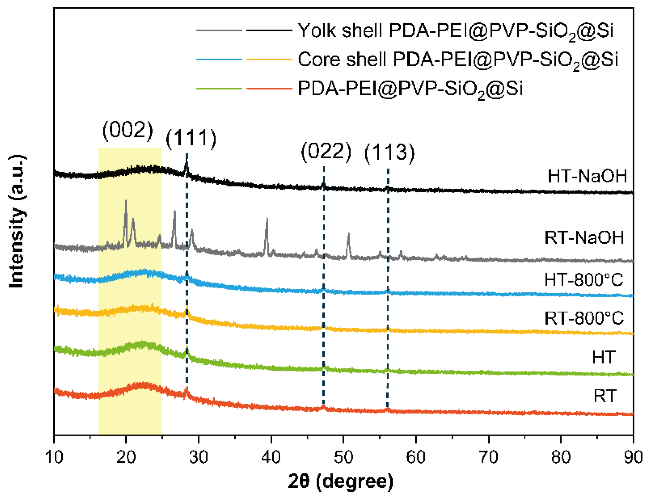
The importance of a hydrothermal treatment in increasing the efficiency and stability of PDA carbon shells has been reported, even after 40 wt.% HF etching for 2 h [66]. Building on this idea, a stable PDA coating to Si can be constructed with satisfactory structural integrity. It is also important for the proposed fabrication process to not alter the inherent crystallinity of the Si active material during template removal. Therefore, the crystallinity of the Si active material was evaluated during the entire composite fabrication process via XRD analysis; Figure 5 presents the results verifying the Si crystallinity.
The crystallinity of the Si active material during the composite fabrication process was monitored via XRD analysis. For comparison, Figure S3 of the SI presents the XRD patterns of the pristine Si nanoparticles, TEOS−SiO2@Si, and APTES/TEOS−SiO2@Si. As shown in Figure 5, the crystallinity of Si is well maintained in both synthetic routes. Apart from the broad peak centered at 2ϴ =26.0° that is attributed to the (002) plane of graphitic carbon materials due to the PDA−PEI carbonization, intense diffraction peaks at 2ϴ = (28.4, 47.3, and 56.1)° were well-indexed to the (111), (220), and (311) facets, respectively, of a typical face-centered cubic Si crystal (Reference code 98-065-2265), presented in Figure S4 of the SI. Representative Si peaks were all observed in the composites with or without the hydrothermal treatment, even after high-temperature pyrolysis. However, after the composite samples without hydrothermal treatment have undergone the etching process, these peaks have disappeared, and multiple intense peaks at various diffraction angles are detected. In contrast, the composite samples synthesized via the proposed hydrothermal route present Si peaks, even after NaOH etching. The XRD results verify the positive effect of hydrothermal treatment in fabricating yolk–shell composites, without altering the Si crystallinity upon template removal.
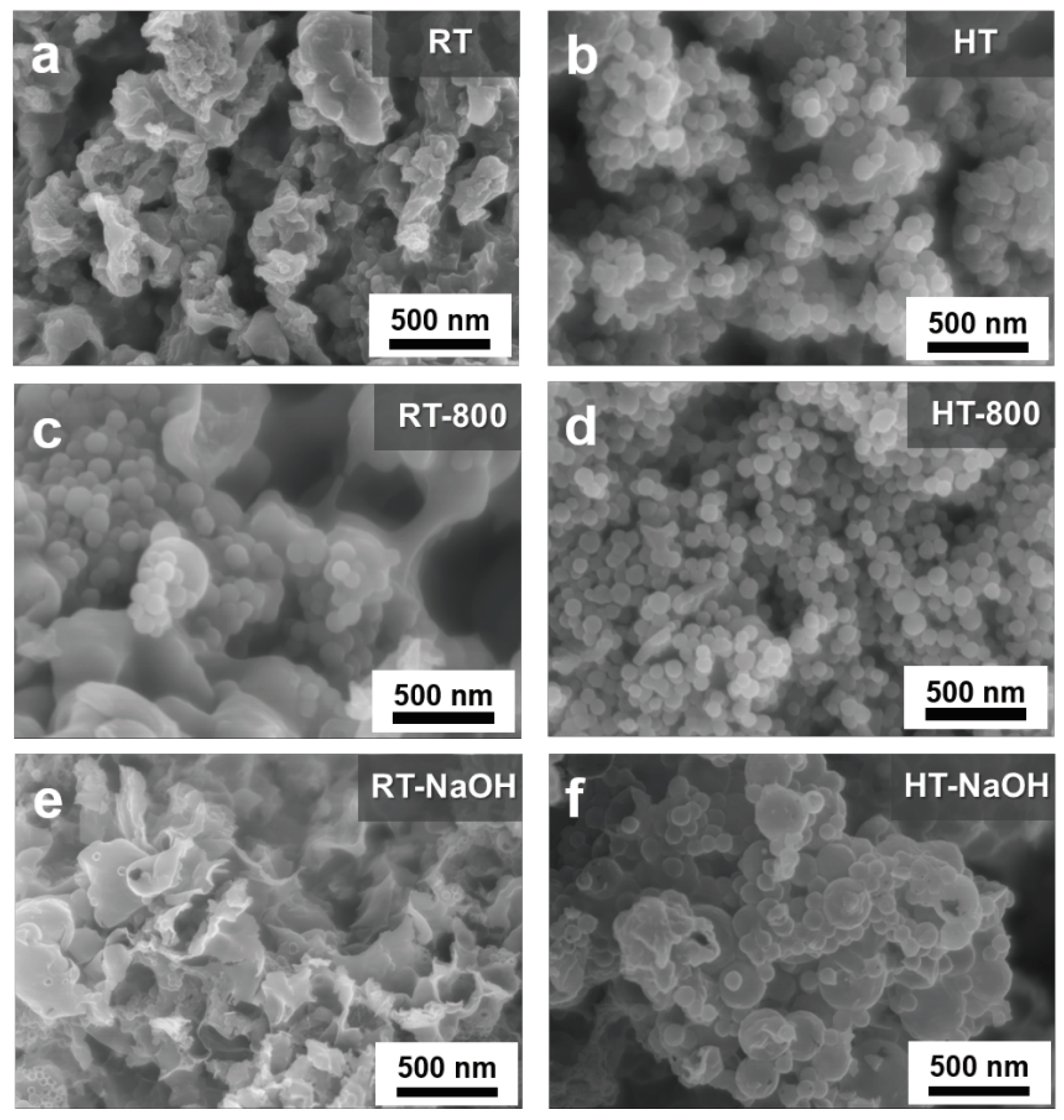
Aside from maintaining Si crystallinity against harsh etching conditions, positive effect on the coating efficiency was also observed in the sample composites prepared via hydrothermal treatment, as compared in Figure 6:
A thin, sheet-like structure enveloping spherical SiO2@Si nanoparticles that were aggregated to a large extent was obtained in a one-pot synthetic route at RT, as shown in Figure 6a. Meanwhile, the composites obtained via the hydrothermal treatment Stöber route illustrated in Figure 6b exhibit well-dispersed SiO2 shells coated with PDA−PEI in a uniform manner, with less aggregation. The dramatic difference between the carbon coating efficiency through both routes is evident in comparing Figure 6c,d after pyrolysis. The uneven carbon coating of RT–composite samples demonstrate exposed APTES/TEOS−SiO2@Si nanoparticles lumped together above sheet-like PDA−PEI carbon structures. Even with PVP-surface protection during NaOH etching, the composites without hydrothermal treatment exhibit severe damage to the carbon network structure, as shown in Figure 6e, wherein the PDA−PEI carbon coating and crosslinking structure were compromised as the SiO2 template was removed. On the other hand, the composite samples prepared with hydrothermal treatment were able to maintain distinguishable PDA carbon coatings with almost no damage to the structure, as shown in Figure 6f. The TEM images in Figure S5 of the SI provide a visual insight into the effect of hydrothermal treatment, which resulted in a more complete PDA carbon coating and PEI crosslinking to the APTES/TEOS−SiO2@Si nanoparticles.

3.3. Significance of PVP K30 Surface Protection during NaOH Etching

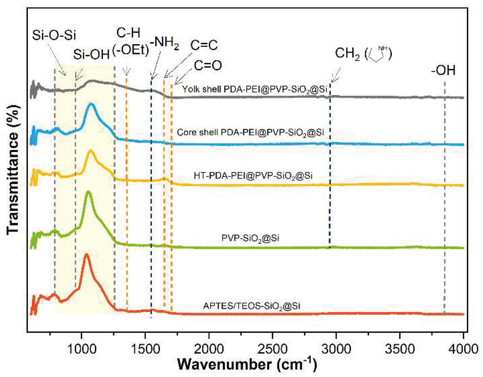
The direct loading of the PVP K30 polymer was studied by comparing the chemical bonds present in the composite samples during the entire fabrication process. FTIR analysis was conducted to verify the successful loading of the PVP K30, and Figure 7 presents the resultant spectra:
The abundant surficial –OH groups previously detected at ~3,400 cm−1 after piranha pre-treatment disappeared completely from all sample spectra, which can be interpreted as a result of the successful condensation reactions of the APTES/TEOS. An adsorption band at 1,544 cm−1 corresponding to −NH2 groups is attributed to the amino groups present in the APTES precursor solution [31]. The weak absorption band at 1,348 cm−1 is attributed to the C−H bending vibration of the unhydrolyzed −OEt groups detected on the APTES/TEOS−SiO2@Si, which when the PVP K30 is loaded to yield PVP-SiO2@Si, further reduce in intensity. This observation is attributed to the formation of hydrogen bonds with the SiO2 surface. Additional vibration peaks detected at 2,925 cm−1, assigned to the −CH2 stretching modes in the pyrrolidone ring, C=O stretching band at 1,703 cm−1, and C=C bond at the PVP polymer backbone at 1,645 cm−1, provide further evidence of the successful PVP loading into the SiO2 shells [56]. An increase in the C=C peak can be attributed to the formation of a graphitic carbon structure during hydrothermal treatment, which is due to the polymerization and crosslinking reactions of PDA and PEI polymers. Meanwhile, a broad and intense absorption band in the range (788−1,095) cm−1 corresponding to the symmetric and asymmetric stretching of Si–O–Si bands and Si–OH peak at 947 cm−1 both present for all samples further verifies the complete condensation of APTES/TEOS precursor, and the formation of SiO2 shell [44].
Note also that the intensity of the Si–O–Si bands follows a decreasing trend from sol–gel coating to etching. The decrease in Si–O–Si band after PVP K30 is added can be ascribed to the formation of PVP-treated SiO2 shells. Further decrease in the peak intensity is observed after PDA−PEI is added to form a carbon shell to the SiO2, aligned with the occurrence of a strong C=C peak. The thermal treatment at 800 °C increases the SiO2 stability, which is characterized by a slight increase in the Si–O–Si band intensity. Finally, after NaOH etching, the Si–O–Si band intensity is significantly reduced, dissolving the SiO2 template.
The TEM analysis results shown in Figure 8 comparing sample composites with and without a PVP K30 surface protection highlight the integrity of carbon coating, and whether the spherical morphologies are maintained after etching. The PVP K30-surface protected composites samples shown in Figure 8a,b exhibit excellent stability, with no damage to the PDA−PEI carbon network structure, even after NaOH etching. However, a contrasting difference in the morphologies of the composite samples without PVP K30 protection can be observed in Figure 8c,d, with the majority of PDA carbon shells destroyed, and the sheet-like PEI carbon networks torn apart.
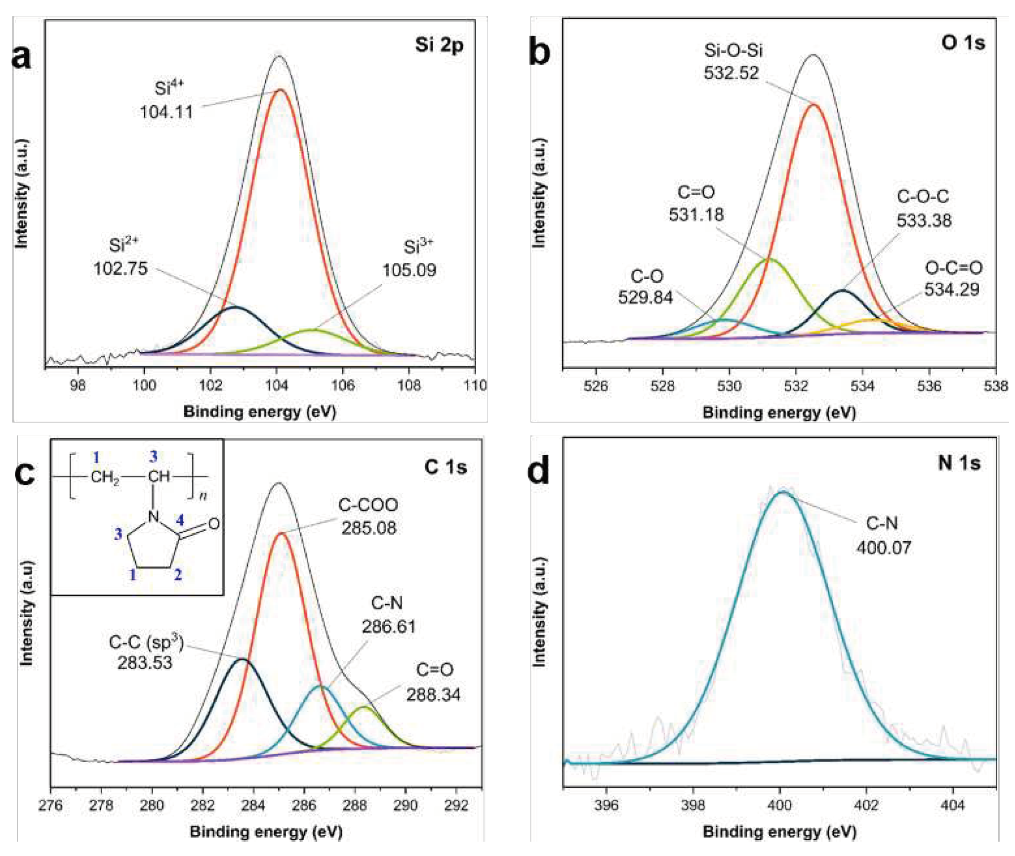
The successful loading of PVP K30 polymer into APTES/TEOS−SiO2@Si is also verified by the XPS analysis shown in Figure 9. The high-resolution Si 2p scans in Figure 9a reveal three peaks at (104.11, 102.75, and 105.09) eV, which are all ascribed to the Si–O–Si band, and the increasing oxidation states of Si into Si2+, Si3+ and Si4+ oxidation states, respectively, related to the synthesis of SiO2 shells after the condensation of APTES and TEOS [59,61]. The O 1s scans in Figure 9b detect peaks at 532.52 eV with a high relative intensity, which are ascribed to the Si–O–Si band of the siloxane networks, with (531.18, 533.38, and 529.84) eV for the C=O, C−O−C, and C−O bonds, respectively, in the PVP molecular structure [67]. The small peak at 534.29 eV is attributed to the O−C=O peak initially identified from the carbon-containing organic groups of the silane precursors used [60]. The C 1s scans in Figure 9c also reveal peaks at (283.53, 285.08, 286.61, and 288.34) eV which originate from the different carbon atoms of the PVP molecules (see inset in Figure 9c) [67]. The peak revealed in the N 1s scan at 400.07 eV in Figure 9d is assigned to the N atoms of C−N from the APTES structure.

3.4. Characterization of Representative Core–Shell and Yolk–Shell Composites

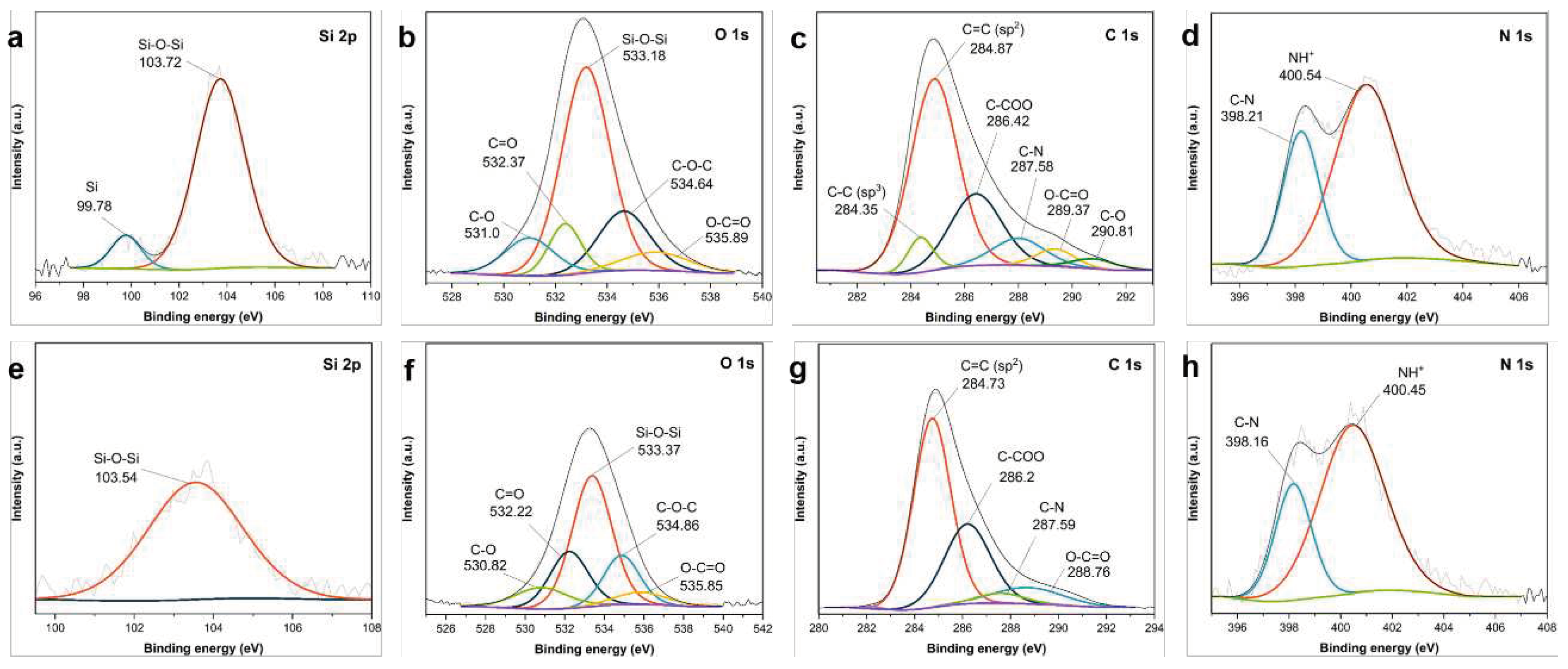
Representative composites bearing core–shell and yolk–shell structures, including a sample composite with a PVP-surface protected SiO2 shells and PEI crosslinked structure, were fabricated following the proposed synthetic route. To study the changes in the surface composition of the fabricated composites with a core–shell and a yolk–shell structure, namely, the core–shell PDA−PEI@SiO2@Si and yolk–shell PDA−PEI@SiO2@Si, XPS analysis was conducted, and Figure 10 presents the results:
The high-resolution Si 2p scan of the core–shell PDA−PEI@SiO2@Si composite sample in Figure 10a reveals two peaks; one at 103.72 eV, which is attributed to the Si–O–Si band with a relatively higher intensity than the peak located at 99.78 eV, which is ascribed to Si [59]. These peaks have been previously identified, and matched with the cited literature. The O 1s scans in Figure 10b are deconvoluted into five components in decreasing order of peak intensity: (533.18, 534.64, 532.37, 531.0, and 535.89) eV for the Si–O–Si band, C−O−C, C=O, C−O, and O−C=O, respectively [60,63]. Meanwhile, the peaks revealed in the C 1s scan were located at the following six peaks in order of decreasing intensity: (284.87, 286.42, 289.37, 284.35, 289.37, and 290.81) for the sp2 C=C bonds, C−COO, C−N, sp3 C−C bonds, O−C=O, and C−O, respectively [62,64]. Similar peaks were observed in the yolk–shell PDA−PEI@SiO2@Si sample, except for the reduced intensities for the O-containing compounds, due to the NaOH etching. For example, the intensity of the Si–O–Si band at 103.54 eV shown in Figure 10e, as well as the O 1s scans in Figure 10f, exhibit a similar reduction in peak intensities for Si–O–Si, C−O−C, C=O, O−C=O, and C−O peaks at (533.37, 534.86, 532.22, 535.85, and 530.82) eV, respectively. However, the peaks for sp3 C−C and C−O bonds in Figure 10c of the core–shell composite disappear in Figure 10g after the removal of SiO2. This observation can be attributed to the destruction of the carbon structures, previously confirmed in Figure 8 showing TEM images of the composite materials without PVP K30 surface protection. The chemical species detected in the O 1s scans align well with the results of C 1s scans all attributed to the SiO2 component, to the carbon-containing ligands of the silanes used, and to the polymer chains of PDA carbon coating compound and PEI crosslinks. Two peaks are revealed in the N 1s scan of the core–shell PDA−PEI@SiO2@Si sample in Figure 10d centered at (400.54 and 398.21) eV, while these peaks in the yolk–shell PDA−PEI@SiO2@Si sample are located at (400.45 and 398.16) eV. These peaks were ascribed to the protonated amines due to APTES hydrolysis and C−N bonds, respectively [63]. The C−N bond that appeared on the O 1s, C 1s, and N 1s scans is attributed to the crosslinking reaction of the amino groups and catechol in oxidized PDA polymer chains with PEI molecules. The formation of the PDA−PEI networks are presumed to be via a Schiff base reaction or a Michael addition reaction mechanism, as illustrated in Figure S6 of the SI [68].
The effect of PVP K30 polymers and the role of PEI crosslinked structures in enhancing the durability of the carbon coating layer is further highlighted in the XPS results of the core–shell PDA@SiO2@Si, when compared to the yolk–shell PDA−PEI@PVP−SiO2@Si composite sample, as shown in Figure 11:
Similar peak observations were detected in the composite samples. For example, the Si 2p of the core–shell PDA@SiO2@Si in Figure 11a detects a similar Si–O–Si band, which also appears in the yolk–shell PDA−PEI@PVP−SiO2@Si sample in Figure 11e, only with a lower peak intensity. Likewise, the O 1s scans in Figure 11b,f in both samples detect similar chemical compositions at very similar binding energies in decreasing order of peak intensities, namely: Si–O–Si, C=O, C−O−C, C−O, and O−C=O. The same observations are made based on the comparison of C 1s scans of both samples illustrated in Figure 11c,g; with peaks for the sp2 C=C, C−COO, C−N, O−C=O, and C−O. Lastly, no significant changes are observed in the N 1s scans of the two composites, as shown in Figure 11d,h. Apart from the obvious reduction in peak intensities of the O-containing groups across all high-resolution scans observed in the PDA−PEI@PVP−SiO2@Si composite samples due to etching, note that the important sp3 C−C peak at 284.47 eV and C−O peak at 289.92 eV in the C 1s of the PVP-surfaced protected composite sample shown in Figure 11g are sustained, in contrast to the non-PVP protected etched composites shown in Figure 10g. This result further verifies the important role of PVP surface protection and the PEI crosslinking in terms of constructing a carbon coating layer that can withstand the NaOH etching necessary for template removal.
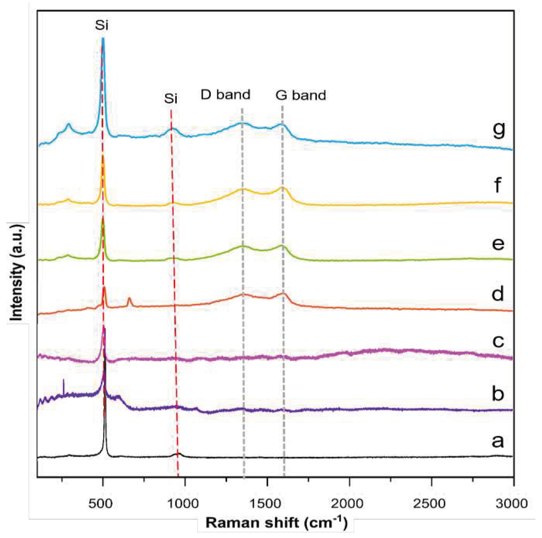
Raman spectroscopy was performed to determine the defect quantity within the carbon coating layer, and identify the degree of graphitization of representative core and yolk–shell composites. Additionally, the TEOS−SiO2@Si, APTES/TEOS−SiO2@Si, and PVP-SiO2@Si samples are also analyzed for reference purposes. Figure 12 summarizes the recorded spectra of each representative composite and reference sample:
The peaks located at (511 and 918) cm−1 related to Si appear in all sample curves, suggesting that the Si crystallinity and inherent properties are maintained. The peak attributed to Si exhibits a decrease in intensity after APTES is added to the precursor mix, implying that after the reaction is completed, the Si is coated with a layer of amorphous SiOx. This decreasing trend in Si peak intensity is further observed after the PVP was loaded onto the SiO2 shells. Meanwhile, all representative composite samples exhibit a characteristic disordered D band at ~1,350 cm−1 and ordered G band at ~1,590 cm−1, typical of graphite and other sp2-bonded carbons after the pyrolysis of PDA and PEI molecules [69]. More importantly, second-order vibrations at ~2,400 cm−1 are shown in the PDA−PEI-containing composites, suggesting that the carbon coating is at least partially graphitic [70]. The relatively stronger G bands compared to the D bands across all the representative composites provide strong indications that the PDA and PEI molecules are integrated into a crystalline graphitic matrix, as initially predicted via the TEM results shown in Figure 3. The relative intensity ratio of the disordered carbon to the graphitized carbon (ID/IG) is quantified for all composite samples after curve fitting using the Gaussian-Lorentzian model, and are shown in Figures S7−S10 of the SI, with corresponding ID/IG ratios, including the fitting parameter values, summarized in Table S1 of the SI [71].
The increase in the ID/IG value of the core–shell PDA@SiO2@Si (0.84) upon the addition of the PEI polymer in the core–shell PDA−PEI@SiO2@Si (0.85) is ascribed to the increase of sp2-carbon edge atoms after the co-polymerization of PDA and PEI, and subsequent graphitization during thermal treatment. A similar increase in ID/IG value is observed for the yolk–shell PDA−PEI@SiO2@Si (0.85), which is attributable to the successful carbonization of the polymer coatings. Although the PVP-SiO2@Si does not show any remarkable variations of the G band peak position or of the ID/IG ratio, this lack of variation can be related to the high intensity of Si signals weakening the carbon contribution from the PVP K30 [72]. The yolk–shell PDA−PEI@PVP−SiO2@Si (0.86) displays the highest ID/IG value among the representative composites, which is attributed to the PDA−PEI graphitization and subsequent carbonization of the PVP K30 polymer chains protecting the SiO2 shells after thermal treatment.
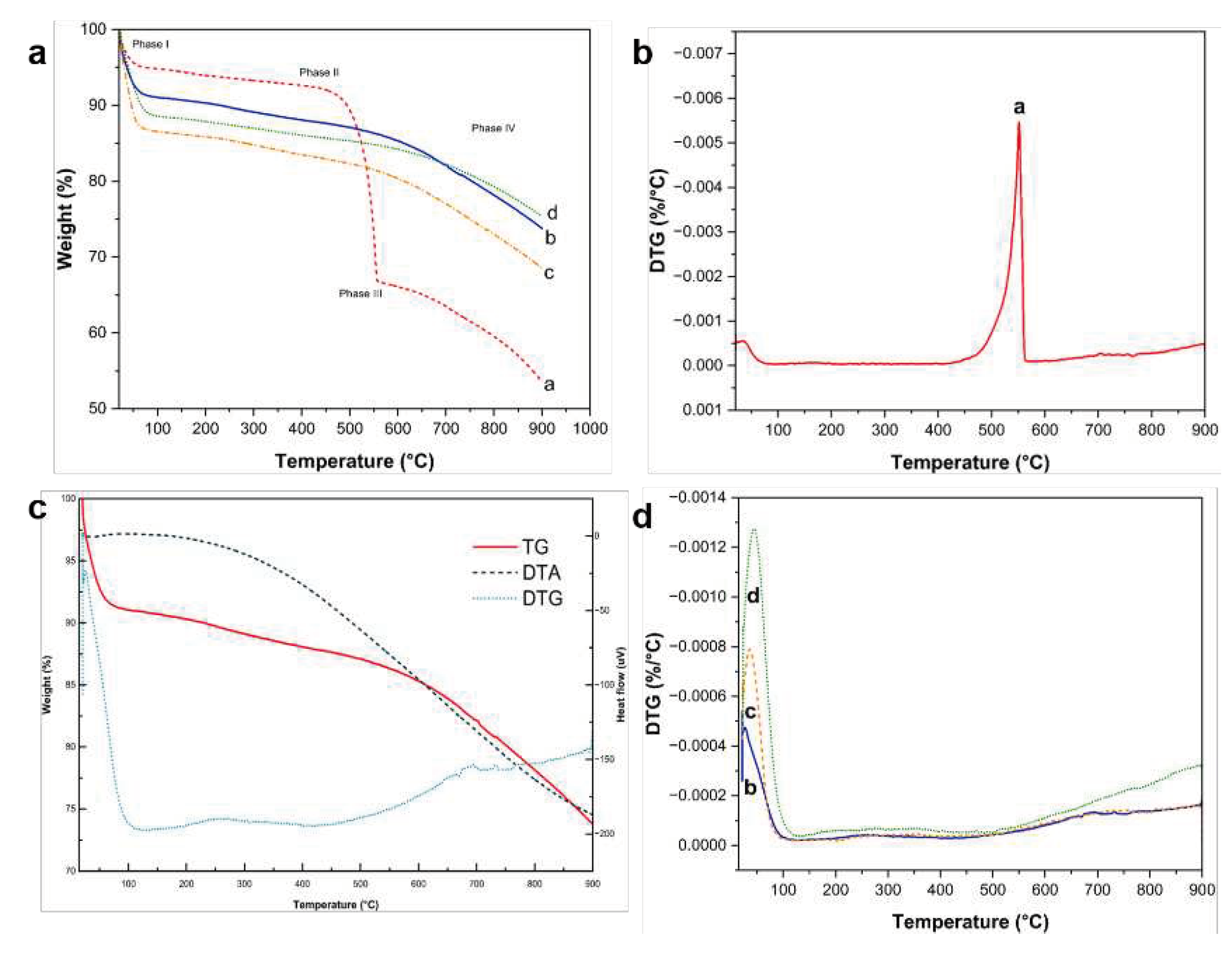
Figure 13 presents the TG/DTA thermograms including the DTG curves of the representative composites during continuous combustion until a temperature cutoff of 800 °C under a N2 gas-protected environment to prevent the rapid oxidation of Si.
The TG profiles in Figure 13a can be divided into four phases based on the composition of representative samples. Phase I, marked by the slight decrease in weight of the samples at ~ (50−90) °C, is due to the loss of moisture from physisorbed water on the surface the composites, followed by actual polymer decomposition over a broad range of temperature, until around 220 °C. Phase II is characterized by the gradual weight loss beginning at ~ (400−550) ºC. The core–shell PDA@SiO2@Si sample exhibits a very sharp decrease in sample weight within this temperature range, due to the rapid degradation of PDA coating without the aid of PEI crosslinks and PVP K30 molecules. This rapid decrease in sample weight is also verified in the DTG profile shown in Figure 13b. Based on the weight decrease recorded in the TG profiles, the total C content of the core–shell PDA@SiO2@Si sample was calculated to be approximately 60 wt.%, in good agreement with the ratio during composite fabrication. Another sample weight loss curve is recorded at ~550 °C, which marks the beginning of Phase III due to the oxidation of exposed Si particles vulnerable to oxidation reactions at elevated temperatures [32]. The oxidation reaction continues during Phase IV until all components in the samples are combusted, except for Si and SiOx components, at ~700 °C. Interestingly, the remaining composite materials with either PEI crosslinking or a PVP K30 surface protection exhibit good thermal stability, characterized by minimal sample weight loss at temperatures higher than 550 °C, due to the effective PDA carbon coating reinforced with PEI crosslink structures.
The increased thermal stability of the PDA−PEI co-polymerized coating structures is verified in the DT−TGA and DTG curves of the representative composite yolk–shell PDA−PEI@PVP−SiO2@Si sample presented in Figure 13c. The TG curve shows a steady and sharp weight loss of ~10 %, which can be associated with the removal of the physisorbed and chemisorbed water. Moreover, the TG curve exhibits a small exothermic peak from ~100 °C, due to moisture loss, a broad endothermic peak centered at (200−400) °C due to polymer decomposition, and a broad exothermic signal starting from 500 °C due to SiO2 oxidation. The DTG curve shows the removal of water from the small endothermic peak observed at ~100 °C and the actual polymer degradation from the broad endothermic peak between ~ (200 and 400) °C. The decomposition of carbon components is confirmed in a broad exothermic signal from ~ (400−550) °C, while endothermic peaks at ~700 °C [73] mark the transition to SiOx.
Apart from the minor loss in sample weight observed at ~ (50−100) °C due to the evaporation of adsorbed water molecules in Figure 13b, no evident changes were observed in the sample weights at 550 °C for the remaining composite samples in Figure 13d. Generally, the total combustion of carbon-based compounds is typically observed from ~ (400−550) °C. However, the representative yolk–shell PDA−PEI@PVP−SiO2@Si composite only displays a slight decrease in sample weight at ~700 °C, suggesting the composite fabrication and design prevent the thermal oxidation of Si. Based on the sample weight loss, the total C content in yolk–shell the PDA−PEI@PVP−SiO2@Si is calculated to be ~18 % while the Si content of ~73 % is from the combined contributions of SiO2 from the APTES, TEOS, and pure Si nanoparticles.

3.5. Electrochemical Performance of the Representative Core–Shell and Yolk–Shell Composites

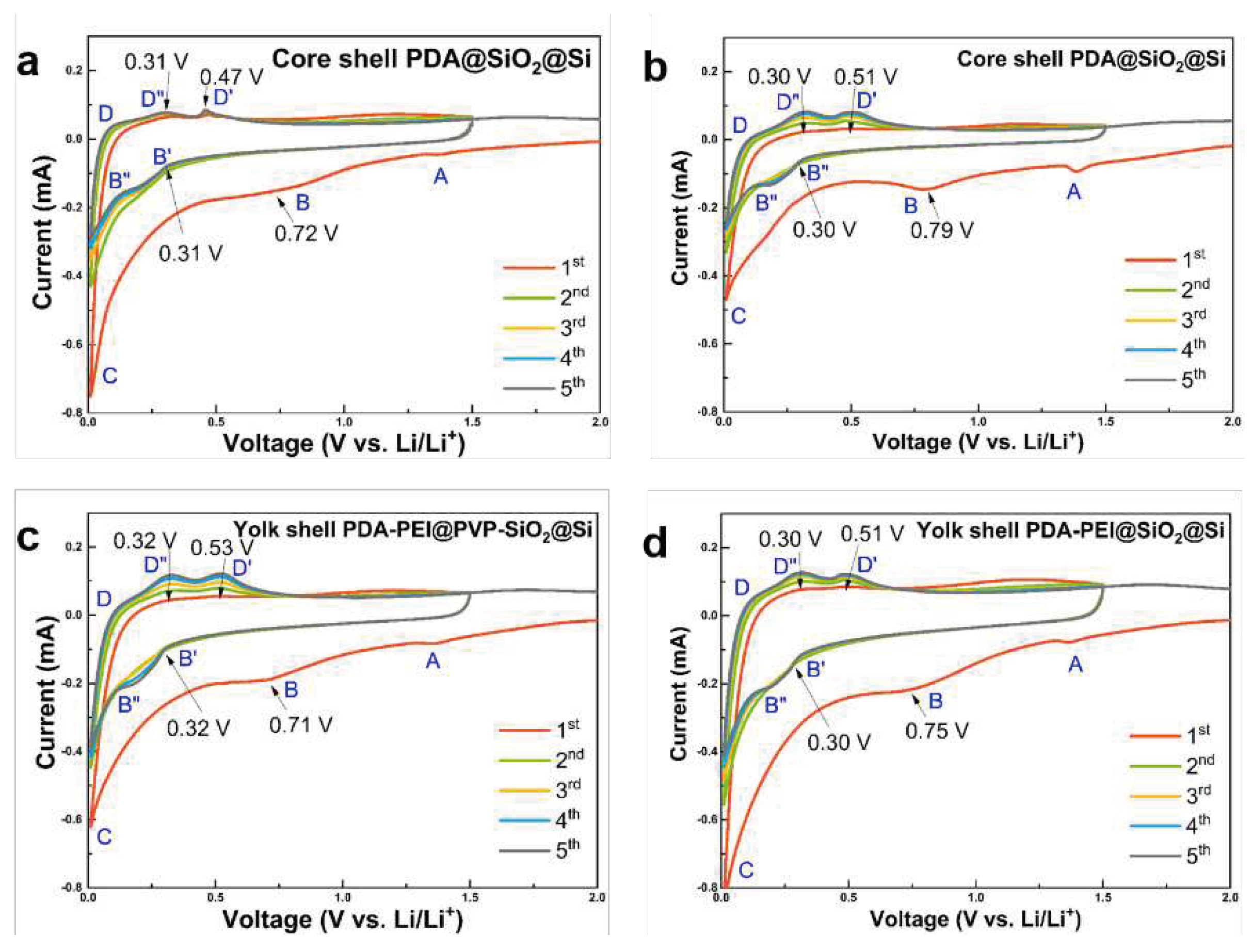
Figure 14 shows the electrochemical performance of the representative yolk and core–shell composite samples that are first characterized by CV.
All composite samples demonstrate two distinct peaks at ((0.30 − 0.32) and (0.72 − 0.79)) V during the first cathodic scan, which are ascribed to the initial electrochemical reactions between the bulk Si and Li+ atoms, which leads to the formation of irreversible lithiated precipitates. Table 1 summarizes the Si phase transformations and corresponding chemical reactions [37]:
The cathodic peaks in the range (0.72 – 0.79) V are attributed to the SEI film formation disappearing in the second cycle, suggesting the stabilization of SEI film after the first cycle. Moreover, two broad oxidation peaks centered at ((0.47 − 0.53) and (0.30 − 0.32)) V in the subsequent anodic scans signify the delithiation processes of Li4.2Si and the complete delithiation into LixSi into amorphous Si, respectively. Although less polarization is observed in the core–shell PDA@SiO2@Si sample in Figure 14a, the hydrothermally-fabricated counterparts in Figure 14b demonstrate electrode activation characterized by gradual, yet steady increase in the intensities of both cathodic and anodic scans in the subsequent cycles. Similar gradual electrode activation is observed in the PVP-surface protected composites in Figure 14c, compared to the less polarized counterpart in Figure 14d. Meanwhile, the CV scans of the core–shell PDA−PEI@TEOS−SiO2@Si composite via RT in Figure S11 of the SI demonstrate similar peak observations and peak qualities; however, important oxidation peaks during the delithiation process are not clearly manifest, implying the difficulty in retrieving Li+ from LixSi alloyed components during the reaction.
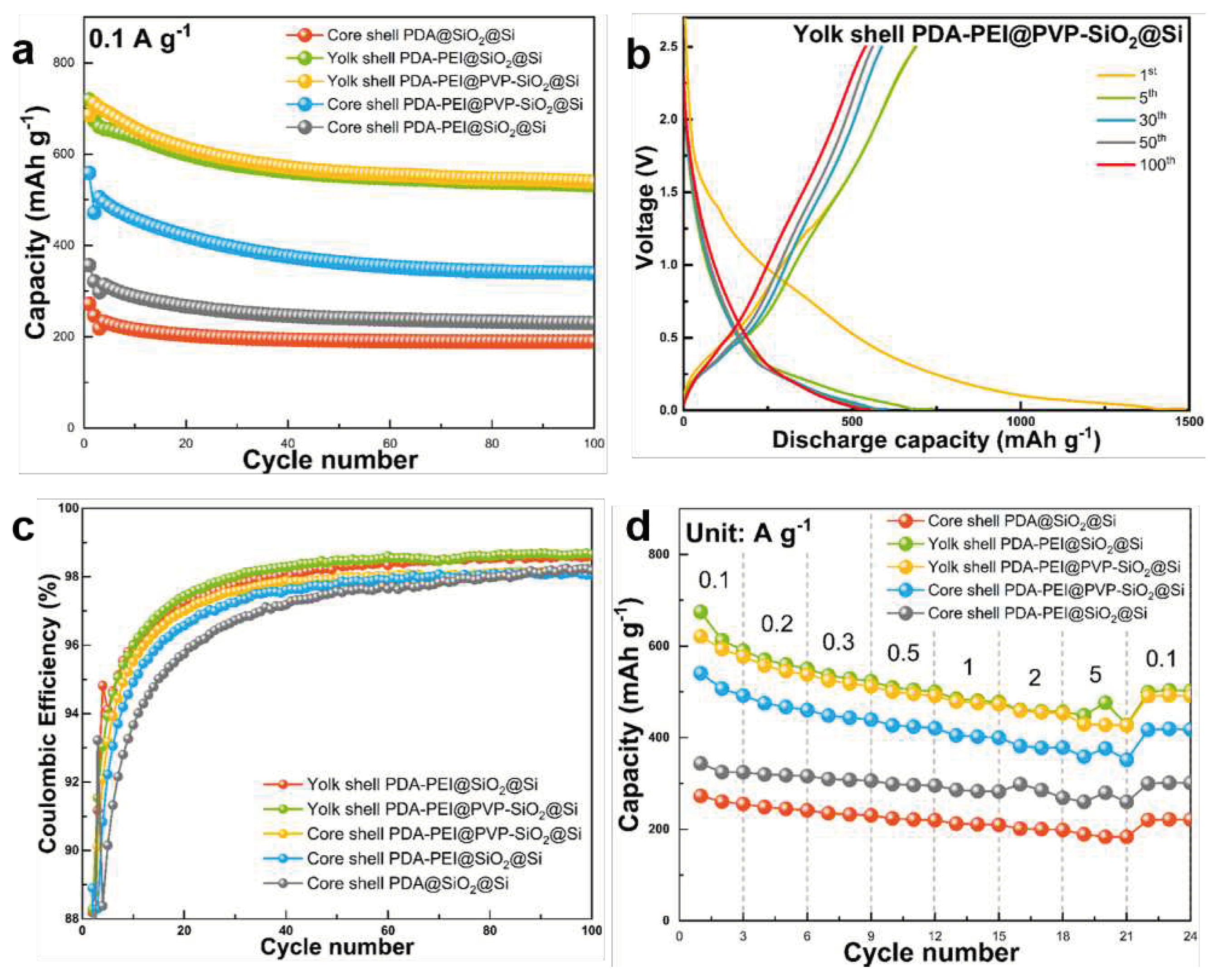
Figure 15 compares the electrochemical performance of the composites in terms of cycling stability, rate performance, and CE stability over 100 cycles. Figure S12 of the SI also presents the galvanostatic charge and discharge profiles of the other composites.
The influence of the core–shell and yolk–shell structures and PVP surface protection and PDA−PEI carbon crosslinking on the electrochemical performances is evaluated at a low current density of 0.1 A·g−1 for 100 cycles, as reflected in Figure 15a. Among the studied composites, the representative yolk–shell PDA−PEI@PVP−SiO2@Si sample exhibits the highest discharge capacity of 719 mAh·g−1 with an initial CE (ICE) value of 47.94 %, which after five cycles readily increases to 94 %, and during the subsequent cycles, maintains more than 98 %. The galvanostatic charge and discharge profiles of the representative composite presented in Figure 15b also show minimal electrode polarization with overlapping profile scans over increasing cycle number. Generally, the low ICE values of the Si-based composite anodes are due to the decomposition reaction at the SEI interface, consuming Li+ in the process, hence the decreased available reversible Li+ to participate in electrochemical reactions during the initial cycles. The representative yolk–shell PDA−PEI@PVP−SiO2@Si sample was able to retrieve 539 mAh·g−1 discharge capacity after 100 cycles with a CE value of 98 %. Moreover, the CE was stabilized after the initial SEI formation, as shown in Figure 15c.
Overall, the yolk–shell composite samples demonstrate better cycling performance and CE stability, even without the PVP K30 surface protection. For example, the yolk–shell PDA−PEI@SiO2@Si composite sample without PVP K30 is able to maintain capacity of 531.25 mAh·g−1 after 100 cycles. Meanwhile, even with the help of PVP K30 surface protection, the core–shell PDA−PEI@PVP−SiO2@Si composite sample demonstrates inferior cycling performance with only 339.62 mAh·g−1 of capacity after 100 cycles. This result highlights the role of void spaces in yolk–shell structures that are sufficient to absorb the internal volume changes of Si, and stabilize the cycling performance. With both PDA−PEI@SiO2@Si and PDA@SiO2@Si composites possessing core–shell structures, the difference in the cycling performances and CE values can be attributed to the enhanced electronic conductivity of PDA carbon coating due to PEI crosslinking across the entire electrode structure, which provide continuous pathways for fast electron and ion transport.
The rate capabilities of the composite samples were examined at several current densities ranging (0.1 – 5) A·g−1, and Figure 15d summarizes the results. The representative yolk–shell PDA−PEI@PVP−SiO2@Si electrode exhibits better rate performance than the core–shell composites with or without PVP K30 and PEI crosslinking across all current densities, without the formation of Li dendrites. The specific capacities of the yolk–shell PDA−PEI@PVP−SiO2@Si electrode are (621.21, 577.46, 537.96, 512.50, 491.53, 472.71, and 453.16) mAh·g−1 at the current densities of (0.1, 0.2, 0.3, 0.5, 1, 2, and 5) A·g−1. When the current density is returned to 0.1 A·g−1, 490.73 mAh·g−1 is retrieved.
Although the yolk–shell PDA−PEI@SiO2@Si composite performs slightly better, the sudden increase in capacity from (456.32 to 476.41) mAh·g−1 at 5 A·g−1 suggests an open short circuit has taken place due to Li dendritic formations, which typically occur at high current densities. Similar sudden increase in capacities are also observed in the core–shell PDA−PEI@PVP−SiO2@Si and core–shell PDA−PEI@SiO2@Si composites. It is also worth noting that when the current density is reduced to 0.1 A·g−1, the slight increases in capacity observed in other sample composites are all stabilized, implying the ability of the designed composites to recover satisfactory capacities, even after high-rate tests. Table 2 summarizes the cycling and rate performances of the representative yolk–shell PDA−PEI@PVP−SiO2@Si composite against the other fabricated composites:
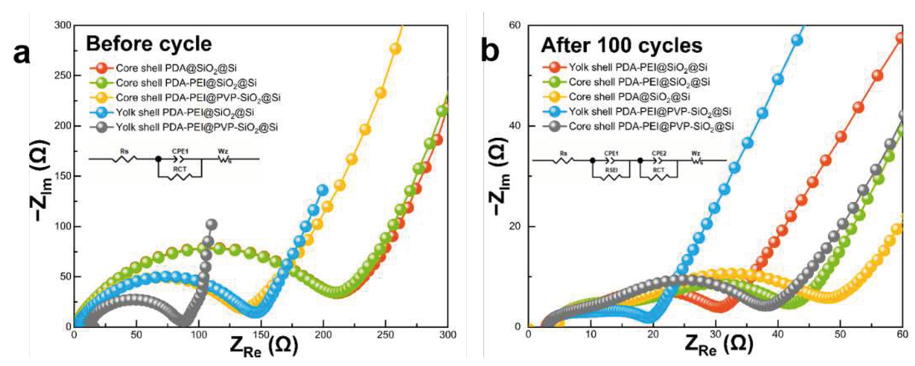
Electrochemical impedance measurements were recorded before and after the 100th cycle to describe the factors that led to the enhancement of Li+ storage capacity of the representative yolk–shell PDA−PEI@PVP−SiO2@Si composite. Figure 16 shows the Nyquist plots that were obtained. The insets in Figure 16a,b show the equivalent circuit models corresponding to Nyquist plots. The resistance value emerging from the interaction of electrolyte solution with the bulk Si denoted as Rs, the resistance of Li+ as it migrates back and forth between the two electrodes passing the SEI layer as RSEI, the resistance value during charge transfer as RCT, and the Warburg impedance denoted as Wz are all considered in the circuit model. Meanwhile, the double-layer capacitance of surface film CPE1 and CPE2 represents the constant phase elements of the cell.
As shown in Figure 16a, the Nyquist plots of the studied composites before cycling are comprised of a semicircle located in the middle-frequency region, and a slanted sloping line in the low-frequency region. The smaller diameter of the representative yolk–shell PDA−PEI@PVP−SiO2@Si before cycling signifies lower resistance value (73.76 Ω), and therefore faster charge transfer. The relatively fast charge transfer kinetics of the representative composite can be attributed to the synergy of yolk–shell structure that allows direct contact of the carbon coating layer with the PVP-SiO2@Si active material. Additionally, the shorter slanted line of the representative composite material implies relatively faster Li+ diffusion rates. The synergistic effect of a yolk–shell structure combined with PVP K30 surface protection can also be observed in the yolk–shell PDA−PEI@SiO2@Si (139.60 Ω) and core–shell PDA−PEI@PVP−SiO2@Si (140.21 Ω), with the PVP K30 showing comparable RCT values, yet much lower than in the core–shell PDA@SiO2@Si (211.16 Ω) and core–shell PDA−PEI@SiO2@Si (209.23 Ω). The thick layer of the amorphous SiO2 coating present in the core–shell composites prevent the direct contact between the Si active material and conductive PDA carbon coating. Therefore, a drastic increase in Li+ tortuosity is observed in the core–shell composites as the Li+ needs to migrate from the PDA coating, passing through the electronically insulating SiO2 layer, before it reaches the Si active material.
After 100 cycles, the Nyquist plots in Figure 16b verify the formation of a stable SEI layer. The Nyquist plots of the fabricated electrodes demonstrate two semicircles; one in the high-frequency region, and the other in the middle-frequency region, which are attributed to the RSEI and RCT, respectively, followed by a slanted line in the low-frequency region. The smallest diameter of the semicircle in the high-frequency zone observed in the representative composite translates to the lowest RSEI value (6.30 Ω). This is due to the formation of a mechanically stable SEI layer thanks to the PDA coating, which prevents excessive electrolyte decomposition. The yolk–shell PDA−PEI@SiO2@Si also demonstrates a relatively lower RSEI (8.13 Ω) value compared to its core–shell counterparts, further supporting the importance of yolk–shell structure. However, the larger RCT value of the yolk–shell PDA−PEI@SiO2@Si (19.28 Ω) compared to the representative composite (9.71 Ω) emphasizes the importance of constructing yolk–shell structures with PVP K30 surface protection. The core–shell composites PDA−PEI@PVP−SiO2@Si (9.51 Ω) with PVP K30 exhibit lower RSEI values than the PDA−PEI@SiO2@Si (10.77 Ω) sample. The stabilized SEI formation in the core–shell PDA−PEI@PVP−SiO2@Si can be explained by acknowledging the influence of PVP K30 polymer chains after being loaded inside amorphous SiO2 shells. Assuming a crack formation in the PDA carbon coating due to expansion of the lithiated Si and SiO2 components, the PVP K30 polymer chains embedded within SiO2 shells provide a secondary barrier that prevents direct contact with the Si active materials. In addition, the flexibility of PVP K30 polymer chains aids SEI stable formation by providing a buffer against the rigid and dense SiO2 layer susceptible to crack formation during repetitive volume fluctuations. The contribution of the embedded PVP K30 polymer chains within SiO2 also help increase the conductivity of the amorphous SiO2 seeds, hence the slight improvement in the RCT of the core–shell PDA−PEI@PVP−SiO2@Si (23.32 Ω), compared to the core–shell PDA−PEI@SiO2@Si (28.01 Ω). On the other hand, the lack of PEI component in the core–shell PDA@SiO2@Si results in higher RSEI (10.84 Ω) coupled with thick SiO2 shells that block Li+ migration, thereby increasing the tortuosity (32.50 Ω). Table 3 summarizes the parameters acquired from the Nyquist plots of the fabricated composites before and after 100 lithiation/delithiation processes.
4. Conclusions

In summary, this paper reported important findings that emphasize the essential function of designing rattle-type, yolk–shell Si/C composite structures from APTES/TEOS dual template-derived SiO2 shells treated with PVP K30 polymers as surface protection against NaOH etching encapsulated within conformal PDA carbon coating layer and dispersed within 3D cross-linked, bubble wrap-like matrix from PEI polymers fabricated via a hydrothermally-assisted modified Stöber process as anode materials for advanced LIB applications. The representative yolk–shell composite sample PDA−PEI@PVP−SiO2@Si delivered an initial discharge capacity of 719 mAh·g−1, and recovered 539 mAh·g−1 capacity after 100 lithiation and delithiation cycles at 0.1 A·g−1. At high current density of 5 A·g−1, the composite sample maintained 453 mAh·g−1 capacity, with no signs of Li dendritic formation.
The satisfactory electrochemical performance of the representative composite over the other studied composites can be attributed to the overall contributions of the proposed synthetic design, which may be summarized as follow: (1) the self-catalytic mechanism of APTES emphasized its dual role as a structure-regulating agent that is able to facilitate the synthesis of spherical SiO2 shells without a base catalyst, and as a precursor to amino-functionalized SiO2 shells with enhanced durability; (2) the PDA carbon coating with high coating efficiency and PEI-copolymerized crosslink structures provided a protective barrier from parasitic electrolyte decomposition, thereby stabilizing the SEI layer and increasing the electronic conductivity of Si via graphitic conductive channels; (3) the yolk–shell structure obtained from SiO2 template removal created void spaces that efficiently catered to the internal mechanical stress from volume-induced fluctuations; (4) the PVP K30 surface protection provided surface protection against harsh NaOH etching and prevented structural damage and crack formation of the carbon structures, while also providing flexibility and increased electronic conductivity to rigid, amorphous SiO2 templates with insulating nature; and (5) the proposed hydrothermal route to composite fabrication offered multiple advantages in terms of increased SiO2 durability to protect Si crystallinity against etching, enhanced PVP K30 loading and improved carbon coating and crosslinking efficiency. The electrode with thermal stability, even at temperatures exceeding 700 °C, and with satisfactory cycle stability and rate performances, could serve as a reference for the development of rattle-type Si/C anode materials for advanced EV applications.

Supplementary Materials

The following supporting information can be downloaded at: www.mdpi.com/xxx/s1, Figure S1: FE-SEM image of (a) the pure Si nanoparticles. (b) FT-IR result comparing the pure Si nanoparticles and Si–OH after piranha solution pre-treatment; Figure S2: (a) Formation of siloxane networks from the piranha-treated Si–OH using APTES. (b) Hydrolysis and (c) condensation reaction mechanism of TEOS, showing the formation of siloxane bridges; Figure S3: XRD patterns of the (a) Si and (b) TEOS-derived SiO2@Si and APTES/TEOS-derived SiO2@Si; Figure S4: XRD reference peaks for the face-centered cubic Si crystal (Reference code 98-065-2265); Figure S5: TEM images showing carbon crosslinking from PEI and PDA carbon coating efficiency in the (a) & (b) composite samples prepared via the traditional SiO2 sol–gel synthesis reaction and carbon coating at RT, and (c) & (d) composite samples prepared via hydrothermal treatment at 140 °C for 24 h; Figure S6: The two possible reaction mechanisms showing the formation of PDA−PEI carbon crosslinks; Figure S7: Raman peak fitting of the core–shell PDA@SiO2@Si composite sample; Figure S8: Raman peak fitting of the yolk–shell PDA−PEI@SiO2@Si composite sample; Figure S9: Raman peak fitting of the yolk–shell PDA−PEI@PVP−SiO2@Si composite sample; Figure S10: Raman peak fitting of the core–shell PDA−PEI@SiO2@Si composite sample; Figure S11: CV scans of the core–shell PDA−PEI@TEOS−SiO2@Si composite fabricated at RT using TEOS as precursor solution; Figure S12: Galvanostatic charge and discharge profiles of the (a) core–shell PDA@SiO2@Si, (b) core–shell PDA−PEI@SiO2@Si, (c) core–shell PDA−PEI@PVP−SiO2@Si, and (d) yolk–shell PDA−PEI@SiO2@Si composite samples; Table S1: The ID/IG values of the samples calculated by the ratio of the D band peak area to the G band peak area using the Gaussian–Lorentzian curve fitting model.

Author Contributions

Conceptualization, methodology, data curation, visualization, and writing—original draft preparation, AM; investigation, data curation, electrochemical measurements in Figure 14, Figure 15 and Figure 16, JJ and HL; resources, formal analysis, HHP; funding acquisition, writing—review and editing, supervision, project administration, CSL. All authors have read and agreed to the published version of the manuscript.

Funding

This research was funded by the KOREA EVALUATION INSTITUTE OF INDUSTRIAL TECHNOLOGY, grant number 20220488.

Data Availability Statement

The datasets generated and/or analyzed during the current study are available from the corresponding author upon reasonable request.

Conflicts of Interest

The authors declare no conflict of interest. The funders had no role in the design of the study; in the collection, analyses, or interpretation of data; in the writing of the manuscript; or in the decision to publish the results.

References

  1. Turner, W. R., Bradley, B. A., Estes, L. D., Hole, D. G., Oppenheimer, M., & Wilcove, D. S. Climate change: Helping nature survive the human response. Conserv. Lett. 2010, 3(5), 304–312. [CrossRef]
  2. United Nations (UN). Paris Agreement; UN: Geneva, Switzerland, 2015; Available online: https://unfccc.int/files/essential_background/convention/application/pdf/english_paris_agreement.pdf (accessed on 31 October 2023).
  3. United Nations (UN). United Nations Secretariat Climate Action Plan 2020–2030; UN: Geneva, Switzerland, 2019; Available online: https://www.un.org/management/sites/www.un.org.management/files/united-nations-secretariat-climate-action-plan.pdf (accessed on 1 November 2023).
  4. European Union (EU). 2050 Long-Term Strategy; EU: Brussels, Belgium, 2021; Available online: https://ec.europa.eu/clima/policies/strategies/2050_en (accessed on 1 November 2023).
  5. International Energy Agency (IEA). World Energy Outlook 2022. 2022. Available online: https://iea.blob.core.windows.net/assets/830fe099-5530-48f2-a7c1-11f35d510983/WorldEnergyOutlook2022.pdf (accessed on 1 November 2023).
  6. Liang, Y., Kleijn, R., & Van der Voet, E. Increase in demand for critical materials under IEA Net-Zero emission by 2050 scenario. Appl. Energy 2023, 346, 121400. [CrossRef]
  7. Warner, J. T. The handbook of lithium–ion battery pack design: Chemistry, components, types and terminology. Elsevier: Amsterdam, Netherlands, 2015; pp. 76–79. [Google Scholar]
  8. Pistoia, G. Lithium–ion batteries: Advances and applications. Elsevier: Amsterdam, Netherlands, 2014; pp. 437–438. [Google Scholar]
  9. Fasahat, M., & Manthouri, M. State of charge estimation of lithium–ion batteries using hybrid autoencoder and Long Short Term Memory neural networks. J. Power Sources 2020, 469, 228375. [CrossRef]
  10. Wu, F., Yushin, G. Conversion cathodes for rechargeable lithium and lithium–ion batteries. Energy Environ. Sci 2017, 10(2), 435–459. [CrossRef]
  11. Weiss, M., Ruess, R., Kasnatscheew, J., et. al. Fast charging of lithium-ion batteries: A review of materials aspects. Advanced Energy Materials 2021, 11(33), 2101126. [CrossRef]
  12. Yang, C. Running battery electric vehicles with extended range: Coupling cost and energy analysis. Appl. Energy 2022, 306, 118116. [Google Scholar] [CrossRef]
  13. Wu, F., Maier, J., & Yu, Y. Guidelines and trends for next-generation rechargeable lithium and lithium–ion batteries. Chem. Soc. Rev. 2020, 49(5), 1569–1614. [CrossRef]
  14. Zhang, X., Li, Z., Luo, L., Fan, Y., & Du, Z. A review on thermal management of lithium–ion batteries for electric vehicles. Energy, 2022, 238, 121652. [CrossRef]
  15. Maranchi, J. P., Hepp, A. F., & Kumta, P. N. High capacity, reversible silicon thin-film anodes for lithium–ion batteries. ESL 2003, 6(9), A198. [CrossRef]
  16. Hatchard, T. D., & Dahn, J. R. In situ XRD and electrochemical study of the reaction of lithium with amorphous silicon. J. Electrochem. Soc. 2004, 151(6), A838. [CrossRef]
  17. Zhang, W. J. A review of the electrochemical performance of alloy anodes for lithium–ion batteries. J. Power Sources 2011, 196(1), 13–24. [Google Scholar] [CrossRef]
  18. Turcheniuk, K., Bondarev, D., Amatucci, G. G., & Yushin, G. Battery materials for low-cost electric transportation. Mater Today 2021, 42, 57–72. [CrossRef]
  19. United States Geological Survey (USGS). Mineral Commodity Summaries 2023. 2023. Available online: https://minerals.usgs.gov/minerals/ 1030 pubs/mcs/2018/mcs2018.pdf (accessed on 2 November 2023).
  20. Cao, Z., Zheng, X., Zhou, M.; et al. Electrolyte Solvation Engineering toward High-Rate and Low-Temperature Silicon-Based Batteries. ACS Energy Lett. 2022, 7(10), 3581–3592. [CrossRef]
  21. Ryu, J. H., Kim, J. W., Sung, Y. E., & Oh, S. M. Failure modes of silicon powder negative electrode in lithium secondary batteries. ESL 2004, 7(10), A306. [CrossRef]
  22. Wu, B., Chen, C., Danilov; et al. Influence of the SEI formation on the stability and lithium diffusion in Si electrodes. ACS omega 2022, 7(36), 32740–32748. [CrossRef]
  23. Shin, J., Kim, T. H., Lee, Y., & Cho, E. Key functional groups defining the formation of Si anode solid-electrolyte interphase towards high energy density Li-ion batteries. Energy Stor. Mater. 2020, 25, 764–781. [CrossRef]
  24. Yang, Y., Yuan, W., Kang, W.; et al. Silicon-nanoparticle-based composites for advanced lithium–ion battery anodes. Nanoscale 2020, 12(14), 7461–7484. [CrossRef]
  25. Chan, C. K., Peng, H., Liu, G.; et al. High-performance lithium battery anodes using silicon nanowires. Nat. nanotechnol. 2008, 3(1), 31–35. [CrossRef] [PubMed]
  26. Wu, H., Chan, G., Choi, J. W.; et al. Stable cycling of double-walled silicon nanotube battery anodes through solid–electrolyte interphase control. Nat. Nanotechnol. 2012, 7(5), 310–315. [CrossRef]
  27. Yao, Y., McDowell, M. T., Ryu, I.; et al. Interconnected silicon hollow nanospheres for lithium–ion battery anodes with long cycle life. Nano Lett. 2011, 11(7), 2949–2954. [CrossRef]
  28. Wada, T., Ichitsubo, T., Yubuta, K.; et al. Bulk-nanoporous-silicon negative electrode with extremely high cyclability for lithium–ion batteries prepared using a top-down process. Nano Lett. 2014, 14(8), 4505–4510. [CrossRef]
  29. Goldman, J. L., Long, B. R., Gewirth, A. A., & Nuzzo, R. G. Strain anisotropies and Self-Limiting capacities in Single-Crystalline 3D silicon microstructures: Models for high energy density Lithium-Ion battery anodes. Adv. Funct. Mater. 2011, 21(13), 2412–2422. [CrossRef]
  30. Fan, S., Wang, H., Qian, J.; et al. Covalently bonded silicon/carbon nanocomposites as cycle-stable anodes for Li-ion batteries. ACS Appl. Mater. Interfaces 2020, 12(14), 16411–16416. [CrossRef] [PubMed]
  31. Cong, R., Jo, M., Martino, A.; et al. Three-dimensional network of nitrogen-doped carbon matrix-encapsulated Si nanoparticles/carbon nanofibers hybrids for lithium–ion battery anodes with excellent capability. Sci. Rep. 2022, 12(1), 16002. [CrossRef]
  32. Choi, J. Y., Cong, R., Martino, A.; et al. Characteristics and electrochemical performances of nickel@ nano-silicon/carbon nanofibers composites as anode materials for lithium secondary batteries. Bull. Korean Chem Soc 2023, 44(10), 852–864. [CrossRef]
  33. Noh, E., Cong, R., Choi, J. Y.; et al. Synthesis, properties and electrochemical characteristics of SiNPs/CNT/rGO composite films for the anode material of Li ion batteries. Appl. Nanosci. 2022, 12(11), 3207–3218. [CrossRef]
  34. Kwon, S., Jamal, H., Choi, J. Y.; et al. Synthesis and characterization of graphene quantum dot/SiNP/carbon nanomaterial composites. Appl. Nanosci. 2022, 12(11), 3219–3228. [CrossRef]
  35. Cong, R., Choi, J. Y., Song, J. B.; et al. Characteristics and electrochemical performances of silicon/carbon nanofiber/graphene composite films as anode materials for binder-free lithium–ion batteries. Sci. Rep. 2021, 11(1), 1283. [CrossRef]
  36. Hu, R., Sun, W., Chen, Y., Zeng, M., & Zhu, M. Silicon/graphene based nanocomposite anode: Large-scale production and stable high capacity for lithium ion batteries. J. Mater. Chem. A 2014, 2(24), 9118–9125. [CrossRef]
  37. Martino, A., Cong, R., Jo, M.; et al. Characteristics and Electrochemical Performance of Hydroxyl-Functionalized Graphene Quantum Dot-Coated Si Nanoparticles/Reduced Graphene Hybrid Anodes for Advanced Li-Ion Batteries. J. Nanomater. 2023, 2023. [CrossRef]
  38. Ramos, A., Cameán, I., & García, A. B. Graphitization thermal treatment of carbon nanofibers. Carbon 2013, 59, 2–32. [CrossRef]
  39. Whitener Jr, K. E., & Sheehan, P. E. Graphene synthesis. Diam. Relat. Mater 2014, 46, 25–34. [CrossRef]
  40. Landi, B. J., Ganter, M. J., Cress, C. D., DiLeo, R. A., & Raffaelle, R. P. Carbon nanotubes for lithium ion batteries. Energy Environ. Sci, 2009, 2(6), 638–654. [CrossRef]
  41. Lee, J., Kim, K., Park, W. I.; et al. Uniform graphene quantum dots patterned from self-assembled silica nanodots. Nano Lett. 2012, 12(12), 6078–6083. [CrossRef] [PubMed]
  42. Liu, R., Wu, D., Feng, X., & Müllen, K. Bottom-up fabrication of photoluminescent graphene quantum dots with uniform morphology. J. Am. Chem. Soc. 2011, 133(39), 15221–15223. [CrossRef]
  43. Yan, X., Cui, X., & Li, L. S. Synthesis of large, stable colloidal graphene quantum dots with tunable size. J. Am. Chem. Soc. 2010, 132(17), 5944–5945. [CrossRef]
  44. Yang, L. Y., Li, H. Z., Liu, J.; et al. Dual yolk-shell structure of carbon and silica-coated silicon for high-performance lithium–ion batteries. Sci. Rep. 2015, 5(1), 10908. [CrossRef]
  45. Lee, J., Moon, J., Han, S. A.; et al. Everlasting living and breathing gyroid 3D network in Si@SiOx/C nanoarchitecture for lithium ion battery. ACS Nano 2019, 13(8), 9607–9619. [CrossRef]
  46. Pan, L., Wang, H., Gao, D.; et al. Facile synthesis of yolk–shell structured Si–C nanocomposites as anodes for lithium–ion batteries. Chem comm 2014, 50(44), 5878–5880. [CrossRef]
  47. Yang, Y., Liu, R., Wu, J.; et al. Bottom-up fabrication of graphene on silicon/silica substrate via a facile soft-hard template approach. Sci. Rep. 2015, 5(1), 13480. [CrossRef]
  48. Stöber, W., Fink, A., & Bohn, E. Controlled growth of monodisperse silica spheres in the micron size range. J. Colloid Interface Sci. 1968, 26(1), 62–69. [CrossRef]
  49. Li, W., & Zhao, D. Extension of the Stöber method to construct mesoporous SiO2 and TiO2 shells for uniform multifunctional core–shell structures. Adv. Mater. 2013, 25, 142–149. [CrossRef]
  50. Mogab, C. J., Adams, A. C., & Flamm, D. L. Plasma etching of Si and SiO2—The effect of oxygen additions to CF4 plasmas. J. Appl. Phys. 1978, 49(7), 3796–3803. [CrossRef]
  51. Spierings, G. A. C. M. Wet chemical etching of silicate glasses in hydrofluoric acid based solutions. J. Mater. Sci. 1993, 28, 6261–6273. [Google Scholar] [CrossRef]
  52. Proksche, H., Nagorsen, G., & Ross, D. The Influence of NH 4 F on the Etch Rates of Undoped SiO2 in Buffered Oxide Etch. J. Electrochem. Soc. 1992, 139(2), 521. [CrossRef]
  53. Lou, X. W., Yuan, C., & Archer, L. A. Double-walled SnO2 nano-cocoons with movable magnetic cores. Adv Mater 2007, 19(20), 3328–3332. [CrossRef]
  54. Bühler, J., Steiner, F. P., & Baltes, H. Silicon dioxide sacrificial layer etching in surface micromachining. JMM 1997, 7(1), R1. [CrossRef]
  55. Dai, X., Liu, H., Liu, X.; et al. Silicon nanoparticles encapsulated in multifunctional crosslinked nano-silica/carbon hybrid matrix as a high-performance anode for Li-ion batteries. J. Chem. Eng. 2021, 418, 129468. [CrossRef]
  56. Zhang, Q., Zhang, T., Ge, J., & Yin, Y. Permeable silica shell through surface-protected etching. Nano Lett. 2008, 8(9), 2867–2871. [CrossRef]
  57. Zhang, Q., Ge, J., Goebl, J.; et al. Rattle-type silica colloidal particles prepared by a surface-protected etching process. Nano Res. 2009, 2, 583–591. [CrossRef]
  58. Zhang, H., Xu, H., Wu; et al. A soft–hard template approach towards hollow mesoporous silica nanoparticles with rough surfaces for controlled drug delivery and protein adsorption. J. Mater. Chem. B 2015, 3(31), 6480–6489. [CrossRef] [PubMed]
  59. Post, P., Wurlitzer, L., Maus-Friedrichs, W., & Weber, A. P. Characterization and applications of nanoparticles modified in-flight with silica or silica-organic coatings. Nanomaterials 2018, 8(7), 530. [CrossRef]
  60. Dos Santos, F. C., Harb, S. V., Menu, M. J.; et al. On the structure of high performance anticorrosive PMMA–siloxane–silica hybrid coatings. RSC Adv. 2015, 5(129), 106754–106763. [CrossRef]
  61. Barr, T. L. An XPS study of Si as it occurs in adsorbents, catalysts, and thin films. Appl. Surf. Sci. 1983, 15(1-4), 1–35. [Google Scholar] [CrossRef]
  62. Yu, Q., Ge, P., Liu, Z.; et al. Ultrafine SiO x/C nanospheres and their pomegranate-like assemblies for high-performance lithium storage. J. Mater. Chem. A 2018, 6(30), 14903–14909. [CrossRef]
  63. Maaz, M., Elzein, T., Dragoe, D.; et al. Poly (4-vinylpyridine)-modified silica for efficient oil/water separation. J. Mater. Sci. 2019, 54(2), 1184–1196. [CrossRef]
  64. Scharf, T. W., Ott, R. D., Yang, D., & Barnard, J. A. Structural and tribological characterization of protective amorphous diamond-like carbon and amorphous CN x overcoats for next generation hard disks. J. Appl. Phys. 1999, 85(6), 3142–3154. [CrossRef]
  65. Yamamoto, S., Bluhm, H., Andersson, K.; et al. In situ x-ray photoelectron spectroscopy studies of water on metals and oxides at ambient conditions. J. Phys. Condens. 2008, 20(18), 184025. [CrossRef]
  66. Lin, J., Wang, H., Ren, E.; et al. Stomatocyte-like hollow polydopamine nanoparticles for rapid removal of water-soluble dyes from water. Chem. Commun. 2019, 55(56), 8162–8165. [CrossRef]
  67. Zhang, Y., Liu, J. Y., Ma, S.; et al. Synthesis of PVP-coated ultra-small Fe 3 O 4 nanoparticles as a MRI contrast agent. J. Mater. Sci. Mater. Med. 2010, 21, 1205–1210. [CrossRef]
  68. Yang, H. C., Liao, K. J., Huang, H.; et al. Mussel-inspired modification of a polymer membrane for ultra-high water permeability and oil-in-water emulsion separation. J. Mater. Chem. A 2014, 2(26), 10225–10230. [CrossRef]
  69. Tuinstra, F., & Koenig, J. L. Raman spectrum of graphite. J. Chem. Phys. 1970, 53(3), 1126–1130. [CrossRef]
  70. Lee, Y. J. The second order Raman spectroscopy in carbon crystallinity. J. Nucl. Mater. 2004, 325(2-3), 174–179. [Google Scholar] [CrossRef]
  71. Yuan, X., & Mayanovic, R. A. An empirical study on Raman peak fitting and its application to Raman quantitative research. Appl. Spectrosc. 2017, 71(10), 2325–2338. [CrossRef]
  72. Alvarez Barragan, A., Nava, G., Wagner, N. J., & Mangolini, L. Silicon-carbon composites for lithium–ion batteries: A comparative study of different carbon deposition approaches. J. Vac. Sci. Technol. B 2018, 36(1). [CrossRef]
  73. Waseem, M., Mustafa, S., Naeem, A.; et al. Mechanism of Cd (II) sorption on silica synthesized by sol–gel method. J. Chem. Eng. 2011, 169(1-3), 78–83. [CrossRef]
Figure 1. Schematic of the fabrication process of the core–shell and yolk–shell PDA−PEI@PVP−SiO2@Si composites.
Preprints 91649 g001
Figure 2. FE-SEM images of the (a) TEOS-derived SiO2@Si and (b) APTES/TEOS-derived SiO2@Si via catalyst-free Stöber route synthesis at RT.
Preprints 91649 g002
Figure 3. TEM images of the (ad) TEOS-derived SiO2@Si and (eh) APTES/TEOS-derived SiO2@Si nanoparticles, after a catalyst-free, sol–gel synthesis at RT.
Preprints 91649 g003
Figure 4. XPS high resolution (a,d) Si 2p, (b,e) O 1s, and (c,f) C 1s scans of the (ac) TEOS−SiO2@Si and (df) APTES/TEOS−SiO2@Si samples. The insets of (c,f) show the Si–C peaks within the respective samples.
Preprints 91649 g004
Figure 5. XRD patterns of the core–shell and yolk–shell PDA−PEI@PVP−SiO2@Si composites fabricated from the hydrothermally-assisted modified Stöber (HT) process, compared with the control group fabricated conventional sol–gel reaction at room temperature (RT), before and after pyrolysis, and after the NaOH etching processes.
Preprints 91649 g005
Figure 6. FE-SEM images of the (a,c,e) composite samples prepared via RT, and (b,d,f) HT, before and after pyrolysis and NaOH etching of the SiO2 template.
Preprints 91649 g006
Figure 7. FTIR spectra of the APTES/TEOS−SiO2@Si, PVP-SiO2@Si, HT−PDA−PEI@PVP−SiO2@Si, core–shell PDA−PEI@PVP−SiO2@Si, and yolk–shell PDA−PEI@PVP−SiO2@Si samples with PVP K30-surface protection.
Preprints 91649 g007
Figure 8. TEM images of the composite samples fabricated via the hydrothermal treatment of APTES/TEOS−SiO2@Si seeds (a,b) with, and (c,d) without, PVP K30 surface protection after NaOH etching.
Preprints 91649 g008
Figure 9. XPS high resolution (a) Si 2p, (b) O 1s, (c) C 1s, and (d) N 1s scans of the APTES/TEOS−SiO2@Si after PVP K30 polymer loading via the proposed hydrothermal route. The inset in Figure (c) shows the different carbon atoms in the PVP K30 molecular structure.
Preprints 91649 g009
Figure 10. XPS high-resolution (a,e) Si 2p, (b,f) O 1s, (c,g) C 1s, and (d,h) N 1s scans of the (ad) core–shell PDA−PEI@SiO2@Si and (eh) yolk–shell PDA−PEI@SiO2@Si composite samples.
Preprints 91649 g010
Figure 11. XPS high-resolution (a,e) Si 2p, (b,f) O 1s, (c,g) C 1s, and (d,h) N 1s scans of the (ad) core–shell PDA@SiO2@Si and (eh) yolk–shell PDA−PEI@PVP−SiO2@Si composite samples.
Preprints 91649 g011
Figure 12. Raman spectra of the (a) TEOS−SiO2@Si, (b) APTES/TEOS−SiO2@Si, (c) PVP-SiO2@Si, (d) core–shell PDA@SiO2@Si, (e) yolk–shell PDA−PEI@SiO2@Si, (f) yolk–shell PDA−PEI@PVP−SiO2@Si, and (g) core–shell PDA−PEI@SiO2@Si samples.
Preprints 91649 g012
Figure 13. (a) TG curves of the a. core–shell PDA@SiO2@Si, b. yolk–shell PDA−PEI@PVP−SiO2@Si, c. yolk–shell PDA−PEI@SiO2@Si, and d. core–shell PDA−PEI@SiO2@Si samples. (b) TG-DTA and DTG curves of a representative composite yolk–shell PDA−PEI@PVP−SiO2@Si sample. (c) DTG curves of the core–shell PDA@SiO2@Si sample, and (d) of the other composites.
Preprints 91649 g013
Figure 14. CV profiles of the (a) core–shell PDA@SiO2@Si at RT, (b) core–shell PDA@SiO2@Si by HT, (c) yolk–shell PDA−PEI@PVP−SiO2@Si by HT, and (d) yolk–shell PDA−PEI@SiO2@Si by HT during the initial five cycles.
Preprints 91649 g014
Figure 15. (a) Cycling performance of the composite samples with (b) galvanostatic charge and discharge profiles of the representative yolk–shell PDA−PEI@PVP−SiO2@Si composite sample via HT. (c) The corresponding CE values of composite samples at 0.1 A·g−1 over 100 lithiation/delithiation cycles. (d) Rate performance of the representative composite samples.
Preprints 91649 g015
Figure 16. Nyquist plots and electrochemical impedance spectra of the fabricated composites (a) before cycling, and (b) after 100 lithiation/delithiation cycles.
Preprints 91649 g016
Table 1. Summary of phase transformations in Si nanoparticles during the initial five cycles.
Point in Figure 14 Phase Transformation Chemical Reaction
A SEI formation Si + xLi+ + xe → LixSi; x ≤ 4
B Lithiation of crystalline Si (c-Si) c-Si + xLi → a-LixSi
C Transformation to a new phase at < 50 mV a-LixSi → a-LiySi
D Delithiation of the phase formed at < 50 mV a-LiySi → a-LixSi + (yx’)Li
B’ Lithiation of amorphous Si (a-Si) at > 0.17 V a-Si + x’Li → a-LixSi
B” Lithiation of a-Si between 70 mV and 0.17 V a-LixSi + x”Li → a-Li(x’ + x”)Si
D” Delithiation of a-Si at < 0.38 V a-Li(x’ + x”)Si → a-LixSi + x”Li
D’ Delithiation of a-Si at > 0.38 V a-LixSi → a-Si + x’Li
Table 2. Electrochemical performance of the fabricated composites.
Composite Sample Low-Current Density Performance (at 0.1 A·g−1) High-Current Density Performance
Discharge Capacity
(mAh·g−1)
CR*
(%)
CE
(%)
Discharge Capacity
(mAh·g−1)
1st 5th 99th 100th 100th 1st 5th 100th 1 A·g−1 2 A·g−1 5 A·g−1
Core–shell PDA@SiO2@Si 272.12 228.97 189.64 189.81 99.91 36.72 90.15 98.18 219.81 209.52 198.40
Core–shell PDA−PEI@SiO2@Si 356.68 308.12 230.49 230.32 99.93 42.93 92.23 98.05 295.43 282.43 268.55
Core–shell PDA−PEI@PVP−SiO2@Si 558.84 487.07 339.62 339.19 99.87 46.11 93.18 98.20 420.50 399.83 378.30
Yolk–shell PDA−PEI@SiO2@Si 685.87 653.51 531.90 531.25 99.88 47.15 94.11 98.64 484.92 460.76 453.32
Yolk–shell PDA−PEI@PVP−SiO2@Si 719.11 689.45 539.98 539.44 99.90 47.94 93.93 98.70 491.53 472.71 453.16
*Capacity retention (CR) was calculated from the measured discharge capacity of cycle n+1 divided by the measured discharge capacity of the previous cycle n.
Table 3. Comparison of the fitted parameters obtained from the Nyquist plots of the studied composites.
Composite Sample Resistance Before Cycling (Ω) Resistance after 100 Cycles (Ω)
Rs RSEI RCT Rs RSEI RCT
Core–shell PDA@SiO2@Si ̶ ̶ 211.16 4.85 10.84 32.50
Core–shell PDA−PEI@SiO2@Si ̶ ̶ 209.23 3.89 9.77 28.01
Core–shell PDA−PEI@PVP−SiO2@Si ̶ ̶ 140.21 3.53 9.51 23.32
Yolk–shell PDA−PEI@SiO2@Si ̶ ̶ 139.60 3.30 8.13 19.28
Yolk–shell PDA−PEI@PVP−SiO2@Si ̶ ̶ 73.76 3.21 6.30 9.71
Disclaimer/Publisher’s Note: The statements, opinions and data contained in all publications are solely those of the individual author(s) and contributor(s) and not of MDPI and/or the editor(s). MDPI and/or the editor(s) disclaim responsibility for any injury to people or property resulting from any ideas, methods, instructions or products referred to in the content.
Copyright: This open access article is published under a Creative Commons CC BY 4.0 license, which permit the free download, distribution, and reuse, provided that the author and preprint are cited in any reuse.
Prerpints.org logo

Preprints.org is a free preprint server supported by MDPI in Basel, Switzerland.

Subscribe

© 2024 MDPI (Basel, Switzerland) unless otherwise stated