Preprint
Article

The Comminution of Chert Gravel by Microwave Irradiation for Reuse Optimization of Quarry Areas

Altmetrics

Downloads

60

Views

17

Comments

0

This version is not peer-reviewed

Submitted:

30 November 2023

Posted:

01 December 2023

You are already at the latest version

Alerts
Abstract
Chert rock is a by-product of sand quarrying (about 40% in the geological section). All attempts to use ordinary technologies for aggregate production from chert have been economically unsuccessful, resulting in significant chert "waste" accumulation covering vast quarry areas. This paper presents the study results of the effect of microwave irradiation on the mechanical properties of chert gravel, which is mineralogically relatively homogenous and consists of fine quartz grains. The results show that an increase in irradiation time decreases the strength of chert gravel (by a factor of 4-6 for the 2.5 min of irradiation), while the quenching changes the fractional content of the samples after the crushing test, decreasing the Gravel-to-Sand ratio.
Keywords: 
Subject: Environmental and Earth Sciences  -   Environmental Science

1. Introduction

1.1. The state of the art

The analysis of diverse ore pretreatment techniques, including thermal, chemical, electric, magnetic, ultrasonic, and bio-milling, shows that microwave irradiation causes substantial energy savings and enhances comminution efficiency [1,2,3]. It is known that power density minimally affects irradiation time and energy consumption beyond a specific threshold [4]. At the same time, larger crystals require less time and energy, with marginal changes beyond a particular size [5]. The polarization of minerals exposed to microwaves causes a rise in internal friction, noticeable through the increase in mineral temperatures, resulting in differential thermal expansion and cracking [6,7]. It was shown that the rock degradation effect is achieved when the temperature range is 50-600 °C, with most rocks in the 100-300 °C [8,9]. Minerals are categorized into three primary responses to microwaves: 1) Low-loss materials permit microwaves to pass through without being absorbed; 2) No-loss materials reflect microwaves with minimal energy absorption; 3) High-loss materials, typically dielectrics, fully absorb microwaves [10]. It was noted that quartz shows a weak response to microwave irradiation [4,11,12]. Examining microcrack growth in galena and calcite ore particles under microwave irradiation indicated that mineral shape predominantly impacts microcrack quantity but not their growth behavior [13]. Numerous studies have explored the effect of temperature increase on rock properties [4,5,9], including static and dynamic mechanical [14,15,16,17,18,19,20,21,22], fracture toughness, porosity, and micro-fracturing [23,24,25,26,27,28,29]. The basalt studies revealed significant microcrack differences based on power levels and distances from the antenna, with longer exposures leading to more severe cracks [30]. Subjecting granite samples to microwave treatment significantly reduced the peak and average cutting forces (~10% reduction in average cutting force from untreated to irradiated parts) [31]. It was shown that stresses and damage increased with higher power density, resulting in lower sample strength, while reducing exposure time leads to more significant strength reductions for a given energy input [2,3]. The analysis suggests that fractures form along the boundaries between grains, which can enhance mineral liberation and reduce comminution energy after microwave treatment [32], consistent with the results [33].

1.2. Brief description of chert gravel

The geology of the chert gravels was presented in detail in [34]. The significance of its potential for the industry here is only briefly noted: the Mishor-Rotem region has been previously studied for its mining potential, including oil shale and other materials. Chert rock, a by-product of sand quarrying (about 40% in the geological section), is dark, highly abrasive, and appears between 5 and 20 cm in size. Attempts to use ordinary technologies for aggregate production from chert have been economically unsuccessful, resulting in significant chert "waste" accumulation covering vast quarry areas.
The state-of-the-art analysis shows that irradiation's effect on quartz properties was studied for single-grain quartz minerals or when quartz grains are surrounded by other grains of minerals (e.g., granite rock), the response of which on irradiation is different from that of quartz. This paper presents the study results of the effect of microwave irradiation on the mechanical properties of chert gravel, which is mineralogically relatively homogenous and consists of fine quartz grains [34].

2. Materials and Methods

2.1. Heating and sample types

Chert gravel samples were exposed to microwave radiation from a microwave oven (Model EM823A2GU-6563) operating at a frequency of 2.45 GHz and a maximum power of 900 W. Microwave treatment durations included 1, 1.5, 2, and 2.5 minutes, under the specified conditions:
A. the heating of dried samples with the following sample cooling under room temperature,
B. as in A. while the samples were additionally quenched (hereafter “shock” for simplicity) by immersing the sample in water (at room temperature) just after removing it from the microwave oven,
C. as in A, but the samples were with a wet surface,
D. as in B, but the samples were with a wet surface.

2.2. Strength assessment

Point load tests were carried out to estimate the corresponding index strength of the samples with uneven shapes. The observations were conducted using the MATEST instrument by the ASTM 5130-16 standard. The point load strength index ‘Is’ is generally used for the strength characterization of samples with irregular shapes. It was calculated as follows:
I s = P × 10 3 D 2
where ‘Is’ is the point load strength index, P is the point load force that caused the sample failure (kN), and D is the sample thickness in the direction of load application (in mm). To adjust the value of the point load strength index to the values of samples with standard diameter (50 mm), the following expression is used:
I s ( 50 ) = D 50 0.45 × I s

2.3. Crushing test

A typical crushing study was carried out to understand the effect of microwave irradiation on chert gravel (BS 812:110). After processing (see the procedures in Sect. 2.1. A-D), the gravels were located and placed into a steel cylinder, then loaded using a steel plunger. The cylinder, plunger, and base plate are made of special alloy steel with a hardness of 650 (HV) (57.8 HRC) and protected against corrosion. The cylinder's internal diameter is 150 (mm), height is 130 (mm), and weight is 16.5 (kg) (48-D0510), following BS 812:110. The loading was conducted using the Matest compression machine (MATEST S.P.A TREVOLO 24048) at a rate of 0.05 (mm/sec) up to the maximum applied force of 300 (kN) using strain control. Each test was terminated when the sample deformation reached 40% of the sample's initial height.

2.4. Crushing test

After the crushing test, the aggregate samples were graded based on the Unified Soil Classification System (USCS) method. The USCS system categorizes all soils and aggregates into four primary groups (Gravel, Sand, Mud, and Clay) and their combinations based on particle distribution, particle percentage, plasticity properties, etc. Mineral aggregates used in asphalt and concrete mixes are classified as coarse or fine. For example, index GW means well-graded gravel is a coarse aggregate example, while index SW – well-graded sand belongs to an example of fine aggregate. The set of sieves used for the observation (Figure 1) conforms to the American current ISO 3310-1 and ISO 565 standards, namely, 25 mm, 19 mm, 12.5mm, 9.5 mm, 4.75 mm, 2.36 mm, 1.18 mm, 600 µm, 300 µm, 150 µm, and 75 µm.

3. Results

3.1. The results of temperature measurements

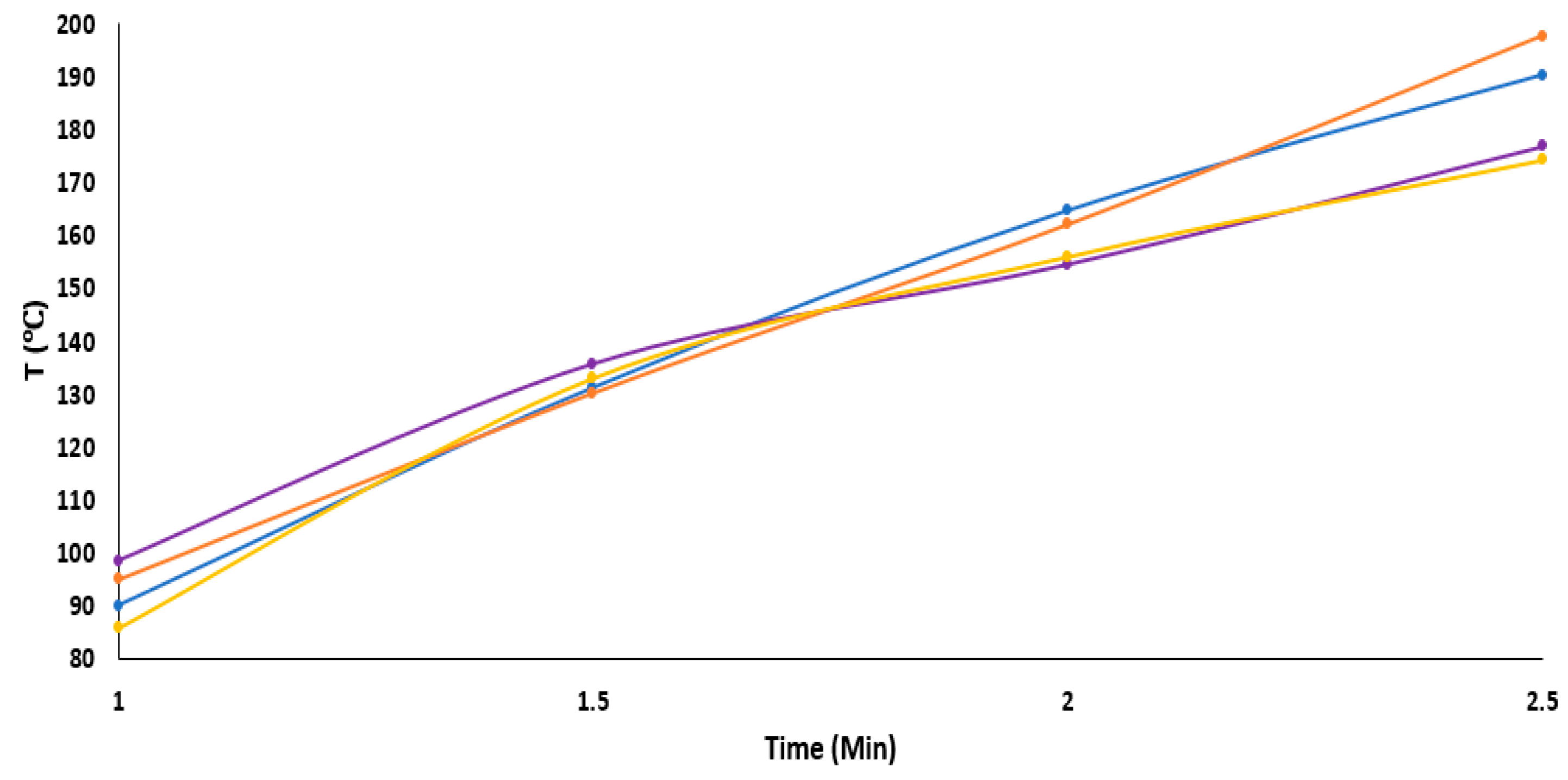
Figure 2 shows the temperature measurement results at the end of irradiation employment as a function of time.
Table 1 presents the results in the table form, while for A-D, see Sect. 2.1 and Figure caption for Figure 2.
It can be seen that the difference in temperature values (between sets A-D) is insignificant and even uneven at the time range between 1-1.5 minutes, while over an irradiation time of 1.5-2 minutes, the slope of the “wet” curves significantly decreases and becomes less than for “dry” curves. Such changes cause the final temperature for "wet" curves to be lower than for "dry" curves by approximately 15-20°C. The consistency of the results across the two pairs of data sets A-B - “dry” and C-D -“wet” is worth noting, respectively.

3.2. The results of the crushing test

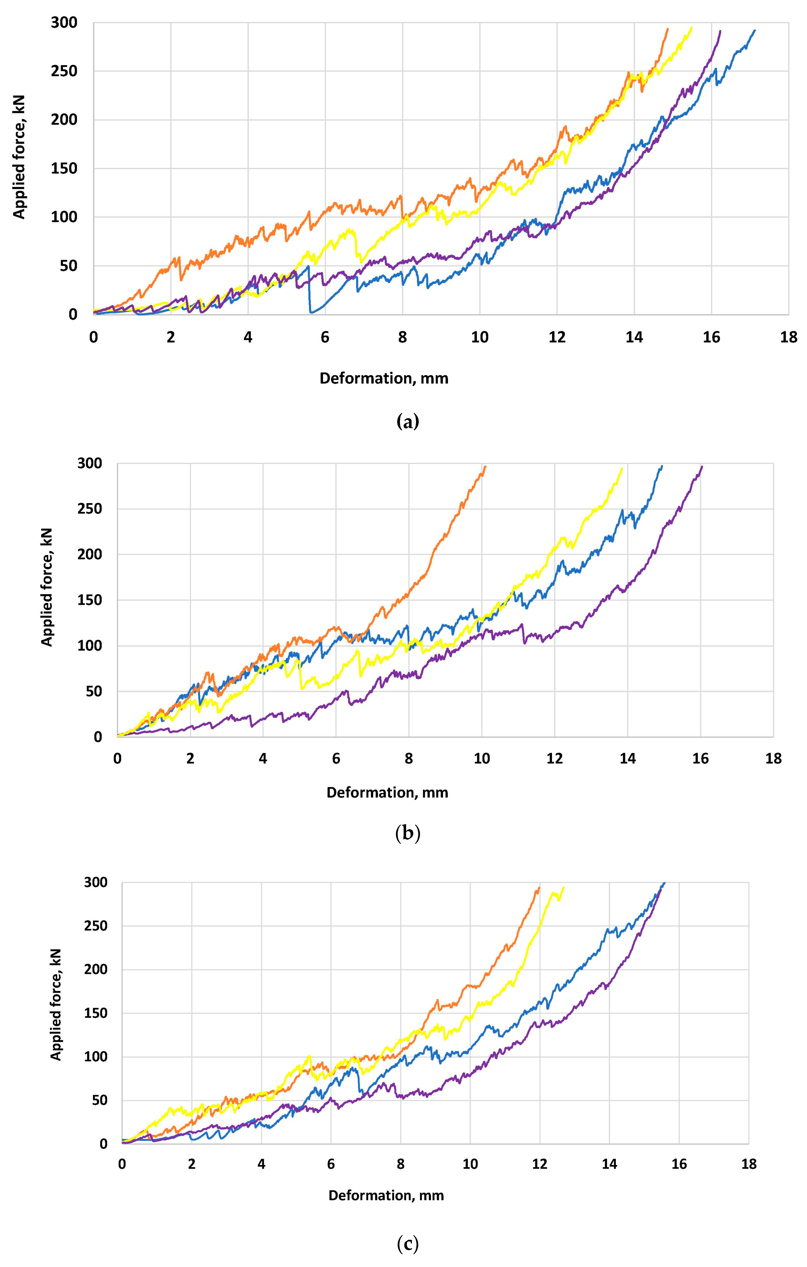
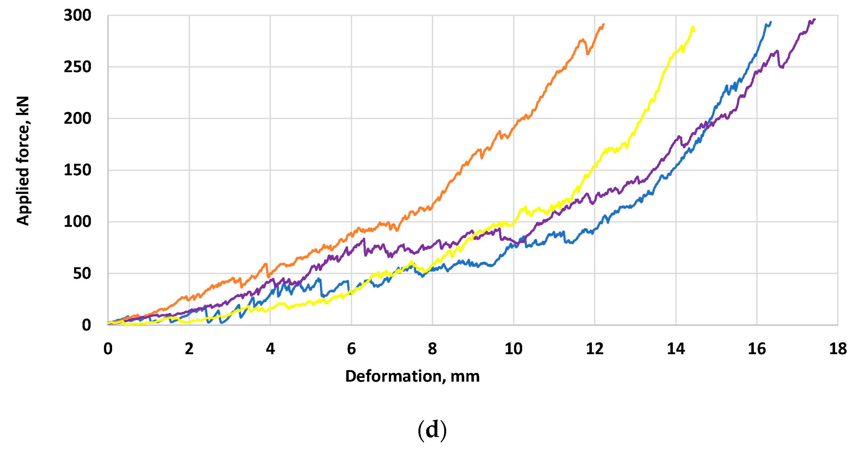
Figure 3 shows typical load-deformation curves of gravel under the standard crushing condition. All curves are characterized by two main parts: a. The applied load is 0-150 kN, b. the applied load ranges 150-300 kN. Stage “a” is characterized by load drops and a low slope of curves, while the curves at stage “b” are smoother than at stage “a”, and their slope is higher. Our preliminary study showed that 150kN is the load needed for course gravel crushing, beyond which there are no unfractured coarse gravel pieces within the loading steel cylinder (Sect. 2.3). Moreover, this load range corresponds to the values of gravel strength observed in our previous study by the uniaxial compression and Schmidt hammer methods [34]. Our analysis showed that an increase in load above 150 kN causes a decrease in gravel size and increases the percentage of sand fraction (0.075-4.75mm).
The application of the quenching procedure causes the crushing of gravels under less final deformation and with a significant deformation gradient, especially when the dry surface gravel was irradiated and then quenched (orange curves in Figure 3, Type B samples - Sect. 2.3). The load-deformation curves for type D samples (yellow curves in 3, the wet-surface samples processed by irradiation and quenching) are close or below the orange ones for all irradiation time under the load higher than 100-150 MPa. The yellow-type curves under the load higher than 150 MPa are not lower than those for samples not quenched. The load below 100-150 MPa corresponds to gravel's preliminary or initial fracturing. Beyond this load level, the deformation curves for all studied samples are much smoother than below (lack of significant stress drops), meaning the lack of extensive fractures created. Note the lack of orange and yellow curves (B and D type samples) below the curves of unquenched samples at a load of more than 150 MPa. Under the load below 150 MPa, the difference between orange and yellow curves is probably due to partial lubrication of sample surfaces (in the case of D-type samples) by a water film at the wet surface. It is seen that the blue and purple curves (A and C type of samples to which the quenching procedure was not applied) are below the orange and yellow curves for all irradiation times while the load level is higher than 150 MPa.
The analysis of sample deformation shows that the quenching application fundamentally affects the deformation behavior, significantly decreasing the final deformation values of the crushing test. It is seen that deformation energy (the area under the curve of deformation) is minor for the A-type samples (the orange curve). The effect of wet surfaces before irradiation application is insignificant.
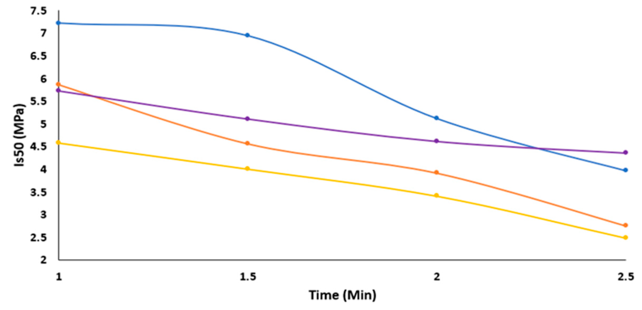
Figure 4 presents the measurement results of the point load strength index versus the microwave irradiation time.
Table 2 presents the values of the point load strength index in the table form, while for A-D, see Sect. 2.1 and Figure caption for Figure 4.
Analysis of Figure 4 and Table 2 shows that after 1 minute of microwave irradiation of dry chert gravel, the value of the point strength index is lower than that of the sample to which irradiation was not applied (Is(50) =12.5 MPa [34]). At the same time, it is more significant for dry samples than for the corresponding samples with a wet surface. An increase in irradiation time (from 1 to 2.5 min) causes a substantial decrease in the strength of gravel by 1.3-2.13 times. Note that the strength of samples after the quenching procedure is 1.45-1.75 times lower than that of samples to which the quenching was not applied. In addition, the strength index of dry samples after irradiation is higher than that of the samples whose surface was wet before irradiation.

3.3. The results of the sieve analysis

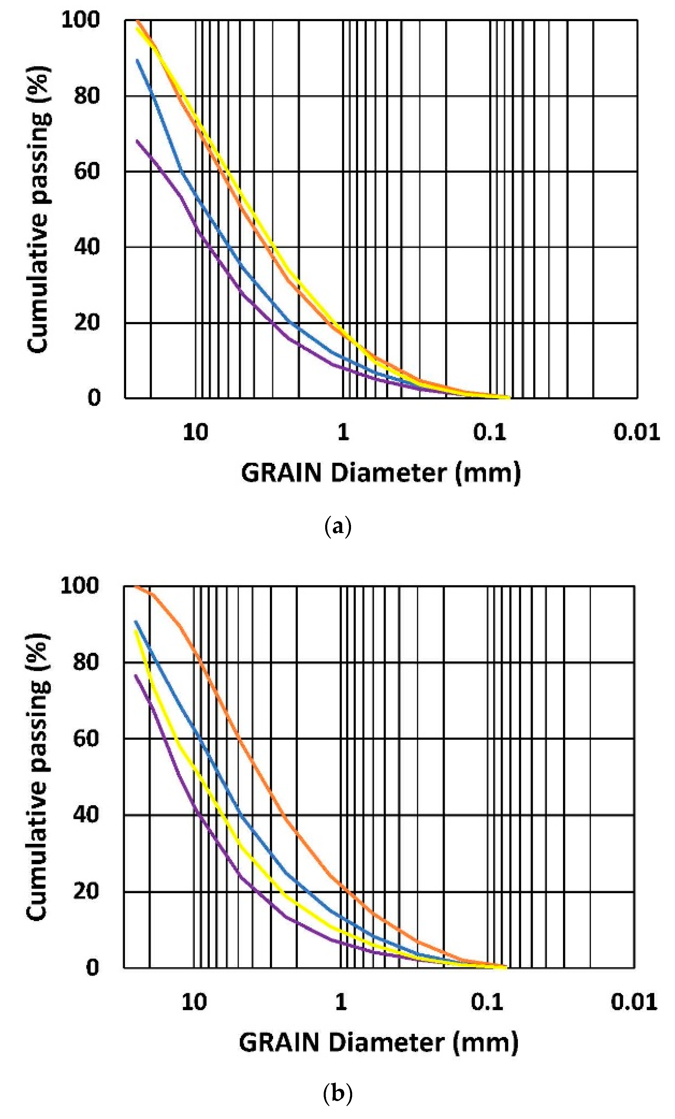
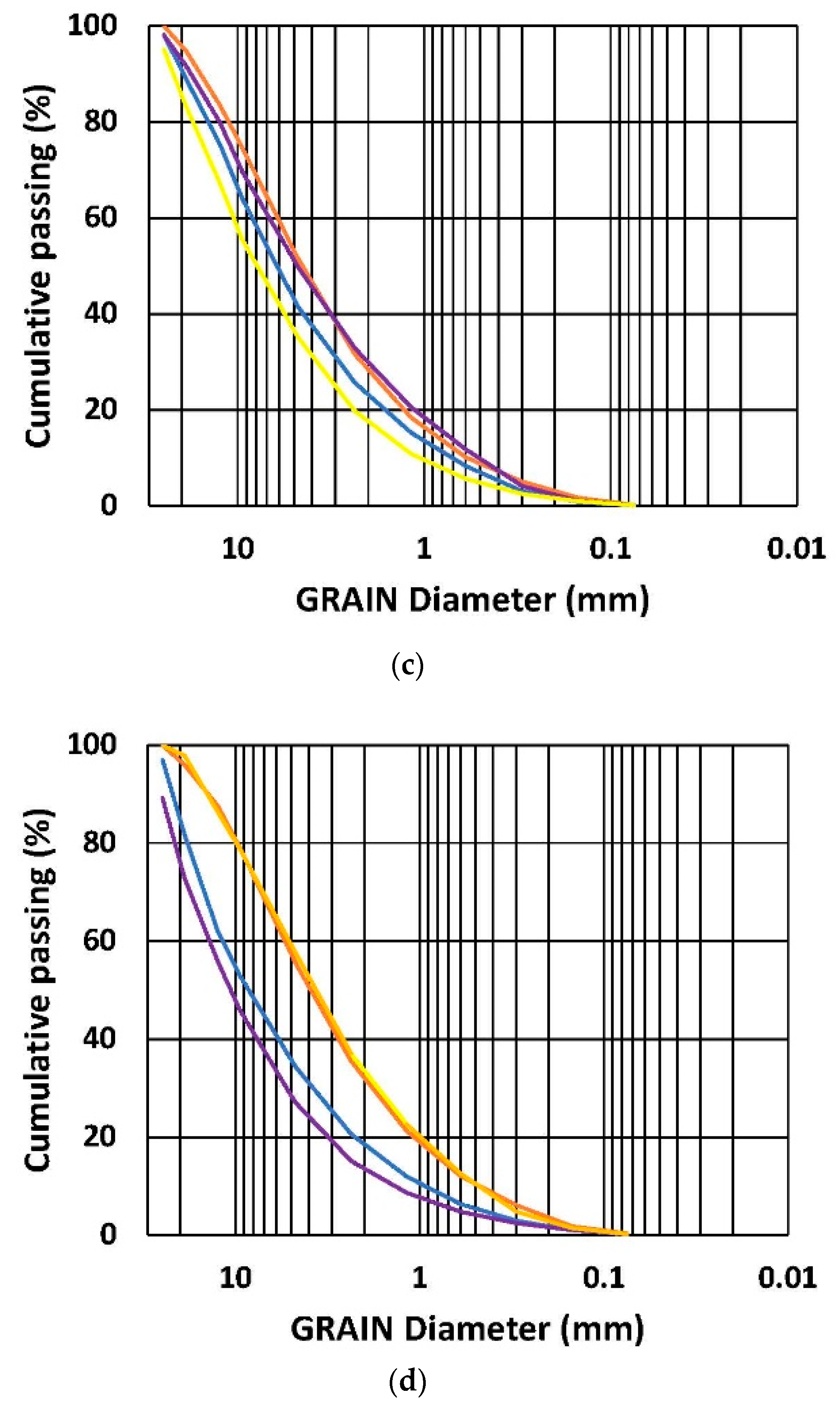
Figure 5 shows a series of grain distribution curves. Table 3 portrays the quantitative grain distribution of the crushing test results.
Analysis of Figure 5 and Table 3 shows that:
A-type samples: A comparison of the grain size ratio between the A-type samples and the samples to which irradiation was not applied shows that the minimal irradiation dose (1 min) significantly changed the Gravel/Sand (G/S) ratio from about 3 to about 2. The decrease in the relative percentage of the coarsest fraction is worth noting, from about 30% to about 20%. An increase in irradiation time between 1-2.5 min does not essentially affect the value of the G/S ratio or the relative percentage of three fractions within the gravel category. The UCSC index for the entire irradiation range is unchangeable – GW and is the same as for the non-irradiated samples.
B-type samples: It is seen that the G/S ratio is ~1 (by factor 2 less than for the samples to which quenching was not applied: A-type). Note the decrease in the percentage of the coarsest gravel fraction and an increase in the finest gravel fraction. The increase in the irradiation time (from 1 to 2.5 min) does not essentially change this result. In comparison with the A-type results, it can be seen that the effect of quenching is much more essential than the effect of an increase in irradiation time. The UCSC index for the entire irradiation range is GW or SW, while both fractions' percentages are similar.
C-type samples: The G/S ratio is ~3, and the relative percentage of three gravel fractions is similar to the results observed for the samples to which the radiation was not applied. This result indicates that an essential part of the irradiation energy was lost on drying the samples’ surface. Note the decrease in the percentage of the coarsest gravel fractions and the increase in the finest gravel fraction. The increase in the irradiation time (from 1 min to 2.5 min) essentially does not change this result. In comparison with the A-type results, it can be seen that quenching is much more essential than the effect of the increase in irradiation time. The UCSC index for the entire irradiation range is unchangeable – GW and is the same as for the non-irradiated samples.
D-type samples: The G/S ratio is ~1-2, and the relative percentage of three gravel fractions varies from the range of B-type and A&C-type samples. The variation in grain size distribution was noted for the C-type samples, implying ambiguity in the irradiation effect, followed by instability in crushing test results. The UCSC index for the entire irradiation range is GW or SW.
In summary, analysis of Figure 5 and Table 3 shows that quenching application increases the appearance of finer fraction (sand) and even the change in classification index from gravel to sand.

4. Discussion and Conclusion

The analysis of the results of the experiments portrays that despite the weak response of quartz on microwave irradiation noted in [4,11,12], the chert gravel can be significantly weakened by this method (Table 2) while the mean temperature on the sample surface (Table 1) is in line with the values presented in [8,9] for the significant number of rocks. However, since the response of quartz grains to microwave irradiation is weak, the considerable decrease in its strength cannot be explained by the appearance of thermal stress only. It can be assumed that the piezoelectric properties of the quartz grains accidentally oriented in the chert matrix can affect the damage process. Let us consider a specific calculation as an example to assess the frequency of vibrations induced by microwave radiation. Our previous study [34] shows that the grain size of chert grains is less than 1-10 µm (5 µm in average). The primary vibration mode is identified by the grain size being half the wavelength λ≈2.5 µm. The speed of sound in quartz is c=5800 m/s. From this, we can calculate the frequency f=c/λ≈2.3 GHz. This value is very close to the microwave frequency applied to the samples and causes the resonance deformation of accidentally oriented quartz grains. The presence of inclusions (Ca, Ba, S, and F) in the chert matrix appears negligible, accounting for less than 1%. Hence, their effect on the matrix disintegration seems to be minor.
Examining the behavior of sample deformation reveals that the quenching process fundamentally impacts deformation behavior, leading to a notable reduction in the final deformation values during the crushing test. Specifically, the deformation energy, represented by the area under the deformation curve, is the lowest for the A-type samples (illustrated by the orange curve - Figure 3). This finding agrees with the findings discussed in [35,36,37], highlighting the significant impact of the quenching cooling process on strength and elastic properties. Namely, the thermal stress induced by the temperature disparity between the rock and the coolant widens existing cracks, initiates new ones, and damages the rock's internal structure. Analysis of Table 3 shows that the utilization of quenching causes a significant increase in the number of cracks and, hence, a rise in the sand fraction (decrease in the Gravel-to-Sand ratio) due to the crushing test.
Wetting the samples’ surface before irradiation does not cause significant changes in the irradiation or quenching results. This is consistent with our previous observation [34], which demonstrated that the value of chert porosity and water absorption is meager (0.34% and 0.13%, respectively).
In summary, our results show that an increase in irradiation time decreases the strength of chert gravel, while the quenching changes the fractional content of the samples after the crushing test, decreasing the Gravel-to-Sand ratio.

Author Contributions

Conceptualization, MT. and VF.; methodology, MT. and VF.; software, MT.; validation, M.T., and V.F.; formal analysis, M.T.; investigation, M.T., and V.F; resources, V.F.; data curation, V.F.; writing—original draft preparation, M.T., and V.F.; writing—review and editing, V.F.; visualization, M.T.; supervision, V.F.; project administration, V.F. All authors have read and agreed to the published version of the manuscript.

Funding

This research was funded by the Ministry of Energy of Israel. The Grant number 3-18116/221-17-21.

Data Availability Statement

All data generated and analyzed during this study are included in the article.

Conflicts of Interest

The authors declare no conflict of interest.

References

  1. Adewuyi, S.; Ahmed, H. Methods of Ore Pretreatment for Comminution Energy Reduction. Minerals 2020, 10, 423. [Google Scholar] [CrossRef]
  2. Jones, D.A.; Kingman, S.W.; Whittles, D.N.; Lowndes, I.S. The influence of microwave energy delivery method on strength reduction in ore samples. Chemical Engineering and Processing 2007, 46, 291–299. [Google Scholar] [CrossRef]
  3. Bradshaw, S.; Louw, W.; van der Merwe, C.; Reader, H.; Kingman, S.; Celuch, M.; Kijewska, W. Techno-Economic Considerations in the Commercial Microwave Processing of Mineral Ores. Journal of Microwave Power and Electromagnetic Energy 2005, 40, 228–240. [Google Scholar] [CrossRef] [PubMed]
  4. Bai, G.; Sun, Q.; Jia, H.; Ge, Z.; Tang, L.; Xue, S. Mechanical responses of igneous rocks to microwave irradiation: a review. Acta Geophysica 2022, 70, 1183–1192. [Google Scholar] [CrossRef]
  5. Qin, L.; Dai, J. Meso-mechanics simulation analysis of microwave-assisted mineral liberation. Frattura ed Integrità Strutturale 2015, 34, 543–553. [Google Scholar] [CrossRef]
  6. Li, Q.; Li, X.; Yin, T. Effect of microwave heating on fracture behavior of granite: An experimental investigation. Engineering Fracture Mechanics 2021, 250, 107758. [Google Scholar] [CrossRef]
  7. Kafashi, S.; Kuhar, L.; Bóna, A.; Nikoloski, A.N. Review of Fracturing Techniques (Microwaves,High-Voltage Pulses, and Cryogenic Fluids) for Application as Access Creation Method in Low-Permeability Hard Rocks for Potential in situ Metal Recovery, Mineral Processing and Extractive Metallurgy Review. 2023. [Google Scholar] [CrossRef]
  8. Adewuyi, S.; Ahmed, H. Grinding Behavior of Microwave-Irradiated Mining Waste. Energies 2021, 14, 3991. [Google Scholar] [CrossRef]
  9. Zheng, Y.L.; Ma, Z.J.; Yang, S.Q.; Zhao, X.B.; He, L.; Li, J.C. A microwave fracturability index (MFI) of hard igneous rocks. International Journal of Rock Mechanics & Mining Sciences 2021, 138, 104566. [Google Scholar]
  10. Wei, W.; Shao, Z.; Zhang, Y.; Qiao, R.; Gao, J. Fundamentals and applications of microwave energy in rock and concrete processing – A review. Appl. Therm. Engng. 2019, 157, 113751. [Google Scholar] [CrossRef]
  11. Zheng, Y.L.; Zhao, X.B.; Zhao, Q.H.; Li, J.C.; Zhang, Q.B. Dielectric properties of hard rock minerals and implications for microwave-assisted rock fracturing. Geomech. Geophys. Geo-energ. Geo-resour. 2020, 6, 22. [Google Scholar] [CrossRef]
  12. Gao, F.; Shao, Y.; Zhou, K. Analysis of Microwave Thermal Stress Fracture Characteristics and Size Effect of Sandstone under Microwave Heating. Energies 2020, 13, 3614. [Google Scholar] [CrossRef]
  13. Qin, L.; Dai, J. Analysis on the growth of different shapes of mineral microcracks in microwave field. Frattura ed Integrità Strutturale 2016, 37, 342–351. [Google Scholar] [CrossRef]
  14. Chen, Y.; Wang, S.; Ni, J.; Azzam, R.; Fernandez-Steeger, T.M. An experimental study of the mechanical properties of granite after high temperature exposure based on mineral characteristics. Engng. Geol. 2017, 220, 234–42. [Google Scholar] [CrossRef]
  15. Peng, J.; Rong, G.; Cai, M.; Yao, M.; Zhou, C. Physical and mechanical behaviors of a thermal-damaged coarse marble under uniaxial compression. Engng. Geol. 2016, 200, 88–93. [Google Scholar] [CrossRef]
  16. Zhang, Q.; Li, X.; Bai, B.; Hu, H. The shear behavior of sandstone joints under different fluid and temperature conditions. Engng. Geol. 2019, 257, 105143. [Google Scholar] [CrossRef]
  17. Lü, C.; Sun, Q.; Zhang, W.; Geng, J.; Qi, Y.; Lu, L. ; The effect of high temperature on tensile strength of sandstone. Appl. Therm. Engng. 2017, 111, 573–579. [Google Scholar] [CrossRef]
  18. Wang, P.; Xu, J.; Fang, X.; Wen, M.; Zheng, G.; Wang, P. Dynamic splitting tensile behaviors of red-sandstone subjected to repeated thermal shocks: Deterioration and micro-mechanism. Engng. Geol. 2017, 223, 1–10. [Google Scholar] [CrossRef]
  19. Wang, P.; Xu, J.; Liu, S.; Wang, H. Dynamic mechanical properties and deterioration of red-sandstone subjected to repeated thermal shocks. Engng. Geol. 2016, 212, 44–52. [Google Scholar] [CrossRef]
  20. Yin, T.; Li, Q.; Li, X. Experimental investigation on mode I fracture characteristics of granite after cyclic heating and cooling treatments. Engng. Fract. Mech 2019, 222, 106740. [Google Scholar] [CrossRef]
  21. Sun, Q.; Zhang, W.; Zhu, Y.; Huang, Z. Effect of High Temperatures on the Thermal Properties of Granite. Rock Mech. Rock Engng. 2019, 52, 2691–2699. [Google Scholar] [CrossRef]
  22. Sun, H.; Sun, Q.; Deng, W.; Zhang, W.; Lü, C. Temperature effect on microstructure and P-wave propagation in Linyi sandstone. Appl. Therm. Engng. 2017, 115, 913–22. [Google Scholar] [CrossRef]
  23. Mahanta, B.; Singh, T.N.; Ranjith, P.G. Influence of thermal treatment on mode I fracture toughness of certain Indian rocks. Engng. Geol. 2016, 210, 103–14. [Google Scholar] [CrossRef]
  24. Zuo, J.; Li, Y.; Zhang, X.; Zhao, Z.; Wang, T. The effects of thermal treatments on the subcritical crack growth of Pingdingshan sandstone at elevated high temperatures. Rock Mech. Rock Engng 2018, 51, 3439–3454. [Google Scholar] [CrossRef]
  25. Yin, T.; Wu, Y.; Li, Q.; Wang, C.; Wu, B. Determination of double-K fracture toughness parameters of thermally treated granite using notched semi-circular bending specimen. Engng. Fract. Mech 2019, 226, 106865. [Google Scholar] [CrossRef]
  26. Sun, Q.; Zhang, Y. Combined effects of salt, cyclic wetting and drying cycles on the physical and mechanical properties of sandstone. Engng. Geol. 2019, 248, 70–79. [Google Scholar] [CrossRef]
  27. Borinaga-Trevino, R.; Orbe, A.; Norambuena-Contreras, J.; Canales, J. Effect of microwave heating damage on the electrical, thermal and mechanical properties of fibre-reinforced cement mortars. Constr. Build. Mater. 2018, 186, 31–41. [Google Scholar] [CrossRef]
  28. Yin, T.; Wang, P.; Li, X.; Wu, B.; Tao, M.; Shu, R. Determination of Dynamic Flexural Tensile Strength of Thermally Treated Laurentian Granite Using Semi-Circular Specimens. Rock Mech. Rock Engng 2016, 49, 3887–3898. [Google Scholar] [CrossRef]
  29. Wang, P.; Yin, T.; Li, X.; Zhang, S.; Bai, L. Dynamic Properties of Thermally Treated Granite Subjected to Cyclic Impact Loading. Rock Mech. Rock Engng 2019, 52, 991–1010. [Google Scholar] [CrossRef]
  30. Teimoori, K.; Hassani, F.; Sasmito, A.P.; Ghoreishi-Madiseh, S.A. Experimental investigations of microwave effects on rock breakage using SEM analysis. 17th international conference on microwave and high-frequency heating. 2019, Valencia, Spain, September 9-12.
  31. Grafe, P.H. Experimental Study on Microwave Assisted Hard Rock Cutting of Granite. BHM, 2017, 162(2), 77-81. [CrossRef]
  32. Jones, D.A.; Kingman, S.W.; Whittles, D.N.; Lowndes, I.S. Understanding microwave assisted breakage. Minerals Engineering 2005, 18, 659–669. [Google Scholar] [CrossRef]
  33. Lu, G.M.; Feng, X.-T. , Li, Y.-H., Hassani, F.; Zhang, X. Experimental Investigation on the Effects of Microwave Treatment on Basalt Heating, Mechanical Strength, and Fragmentation. Rock Mechanics and Rock Engineering 2019, 52, 2535–2549. [Google Scholar] [CrossRef]
  34. Tzibulsky, M.; Frid, V. Features of the properties of chert gravels. Minerals 2023, 13, 455. [Google Scholar] [CrossRef]
  35. Srinivasan, V.; Haseeb Hasainar, T.N. Singh Experimental study on failure and fracturing attributes of granite after thermal treatments with different cooling conditions. Engineering Geology 2022, 310, 106867. [Google Scholar] [CrossRef]
  36. Shao, S.; Ranjith, P.G.; Wasantha, P.B.; Chen, K. Experimental and numerical studies on the mechanical behavior of Australian Strathbogie granite at high temperatures: an application to geothermal energy. Geothermics 2015, 54, 96–108. [Google Scholar] [CrossRef]
  37. Yin, Q.; Wu, J.; Jiang, Z.; Zhu, C.; Su, H.; Jing, H.; Gu, X. Investigating the effect of water quenching cycles on mechanical behaviors for granites after conventional triaxial compression. Geomech. Geophys. Geo-energ. Geo-resour. 2022, 8, 77. [Google Scholar] [CrossRef]
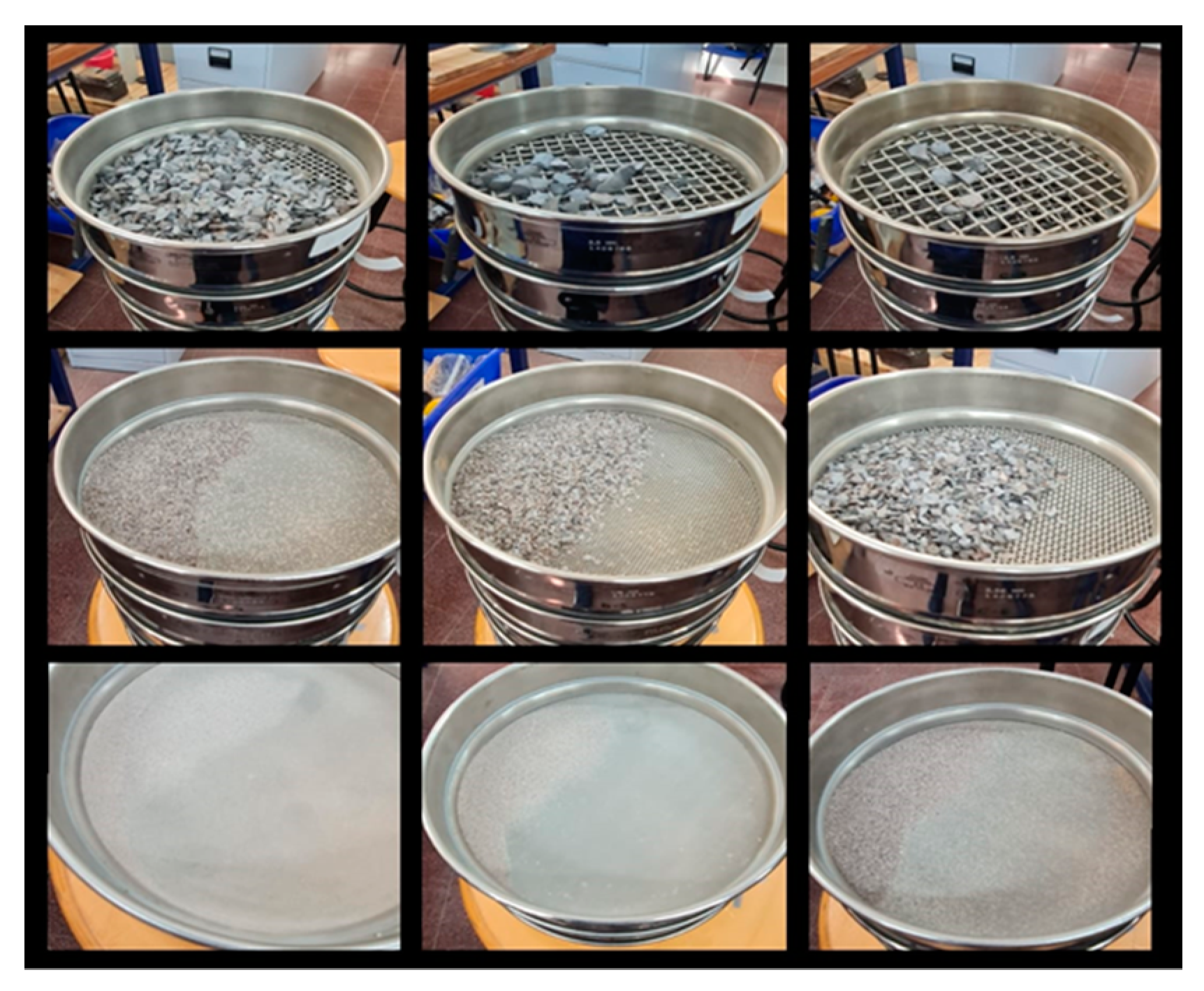
Figure 1. Gravel sieving after crushing test.
Preprints 91955 g001
Figure 2. The results of temperature measurement at the end of the microwave irradiation test. The blue and orange curves portray the results of temperature measurements of samples dried before the test (A and B in Sect 2.1, respectively). In contrast, the purple and yellow curves show the measurement results of the sample with a “wet surface” at the beginning of irradiation (C and D in Sect 2.1, respectively).
Preprints 91955 g002
Figure 3. Typical curves of gravel crushing (a)-(d) 1, 1.5, 2, and 2.5 min of gravel irradiation, respectively. The blue and orange curves display the results for samples with a dry surface at the beginning of the test (A and B in Sect. 2.1, respectively). The purple and yellow curves are the measurement results of samples with a “wet surface” at the beginning of irradiation (C and D in Sect. 2.1, respectively). The orange and yellow curves show results for samples to which the quenching procedure was applied.
Preprints 91955 g003aPreprints 91955 g003b
Figure 4. The results of observation of point load strength index vs. the time of microwave irradiation. The blue and orange curves display the results of measuring the temperature of dry samples at the beginning of the test (A and B in Sect. 2.1, respectively). The purple and yellow curves are the measurement results of samples with a “wet surface” at the beginning of irradiation (C and D in Sect. 2.1, respectively). Note that the orange and yellow curves show results for samples to which the quenching procedure was applied.
Preprints 91955 g004
Figure 5. Typical grain distribution curves of gravel after the crushing while (a)-(d) show the curves after 1,1.5, 2, and 2.5 min of gravel irradiation, respectively. The blue and orange curves display the results for samples with a dry surface at the beginning of the test (A and B in Sect. 2.1, respectively). The purple and yellow curves are the measurement results of samples with a “wet surface” at the beginning of irradiation (C and D in Sect. 2.1, respectively). The orange and yellow curves show results for samples to which the quenching procedure was applied.
Preprints 91955 g005aPreprints 91955 g005b
Table 1. The values of samples’ temperature at the end of microwave irradiation (For A-D, see Sect. 2.1.).
Time A B C D
(min) (℃)
1 90.02 95.0 98.42 85.82
1.5 131.14 130.18 135.66 133.02
2 164.58 161.98 154.48 155.96
2.5 190.24 197.6 176.78 174.22
Table 2. The point load strength index values after irradiation tests for A-D type samples (Sect. 2.1.).
Time Is(50)-A Is(50)-B Is(50)-C Is(50)-D
(min) (MPa)
1 7.219 5.860 5.728 4.576
1.5 6.941 4.559 5.109 4.001
2 5.119 3.913 4.615 3.407
2.5 3.969 2.752 4.359 2.485
Table 3. The results of the sieve analysis of the chert samples after the crushing test.
Time % pass. after
crush. test
% pass. in the range of
Gravel fraction
USCS index
Gravel Sand
>4.75 4.75-0.075 9-25 12.5-19 4.75-12.5
Min mm
A: Irradiation of sample with dry surface (quenching not applied)
1 65.7 34.3 21.00 19.0 25.7 GW
1.5 60.2 39.6 18.3 12.8 29.1 GW
2 58.6 41.3 11 13.6 34 GW
2.5 65.6 34.3 18.3 19.8 27.5 GW
B: Irradiation of sample with dry surface (quenching applied)
1 50.5 49.5 6.9 14.8 28.8 GW/SW
1.5 41.2 58.8 2.3 8.1 30.7 SW
2 48.5 51.5 5.2 11.2 32.1 GW/SW
2.5 44.5 55.6 4.0 8.5 31.9 SW
C: Irradiation of sample with wet surface (quenching not applied)
1 72.6 27.4 37.5 9.4 25.7 GW
1.5 76.4 23.6 32.4 17.7 26.3 GW
2 50.3 49.5 8.3 8.3 11.8 30.2 30.2 GW
2.5 72.9 27.1 27.1 17.1 28.7 GW
D: Irradiation of sample with wet surface (quenching applied)
1 46.9 53 7.7 11.3 27.9 SW
1.5 68.4 31.6 26.3 15.8 26.3 GW
2 64.8 35.2 16.4 16.1 32.1 GW
2.5 42.3 57.7 2.0 11.6 28.5 SW
The typical grain size content of the chert sample to which irradiation was not applied
0 76.6 23.4 33.8 15.4 27.4 GW
Disclaimer/Publisher’s Note: The statements, opinions and data contained in all publications are solely those of the individual author(s) and contributor(s) and not of MDPI and/or the editor(s). MDPI and/or the editor(s) disclaim responsibility for any injury to people or property resulting from any ideas, methods, instructions or products referred to in the content.
Copyright: This open access article is published under a Creative Commons CC BY 4.0 license, which permit the free download, distribution, and reuse, provided that the author and preprint are cited in any reuse.
Prerpints.org logo

Preprints.org is a free preprint server supported by MDPI in Basel, Switzerland.

Subscribe

© 2024 MDPI (Basel, Switzerland) unless otherwise stated