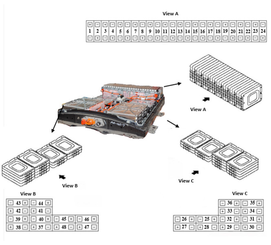
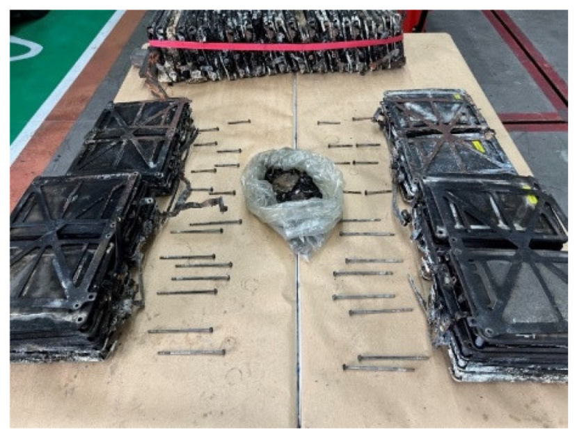
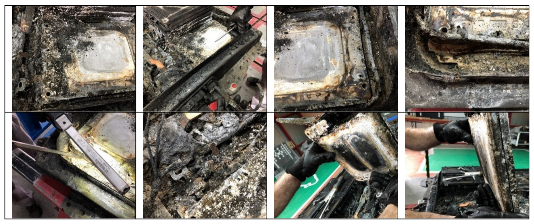
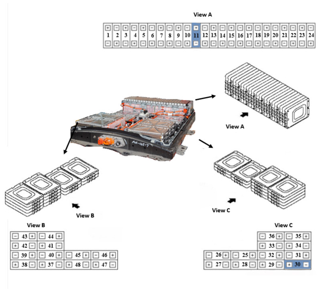
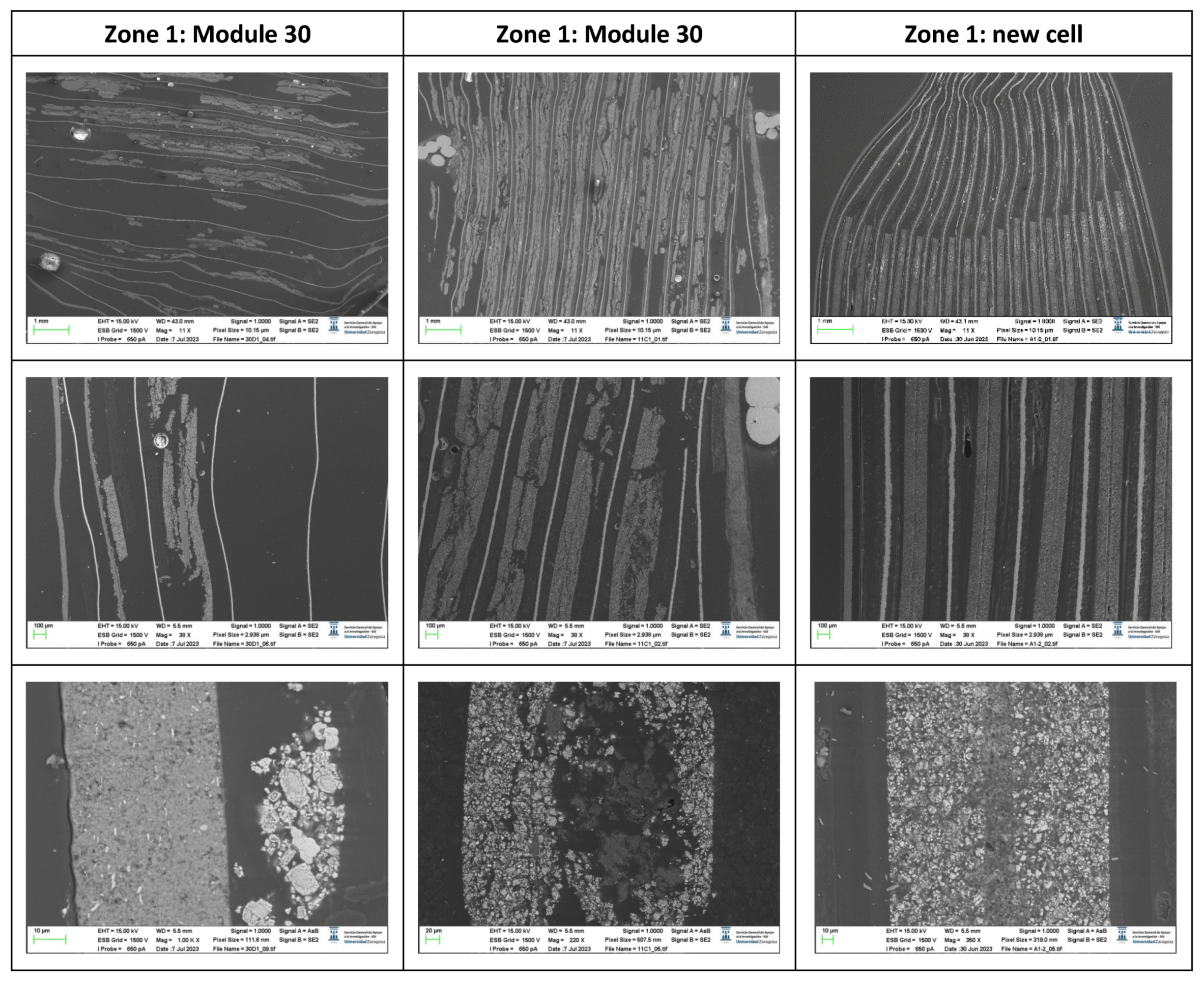
In this section, not only the methods used to derive the surface properties and chemical composition of all the batteries, but also the results of SEM images of transverse-sections of zone 1 (Anode) of an original cell and a cell from module 11 and module 30 of the burnt Nissan Leaf vehicle battery are presented. The surface properties and chemical composition of the different components of an original cell and of a burnt cell from module 11 and module 30 are also analysed. In addition, the thickness of all battery layers is described in detail.
3.3.1. Surface Tests Results: Surface Properties and Chemical Composition Analysis
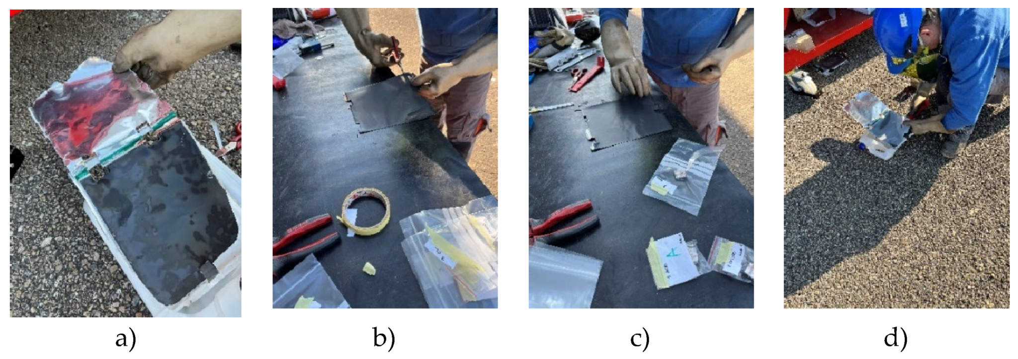
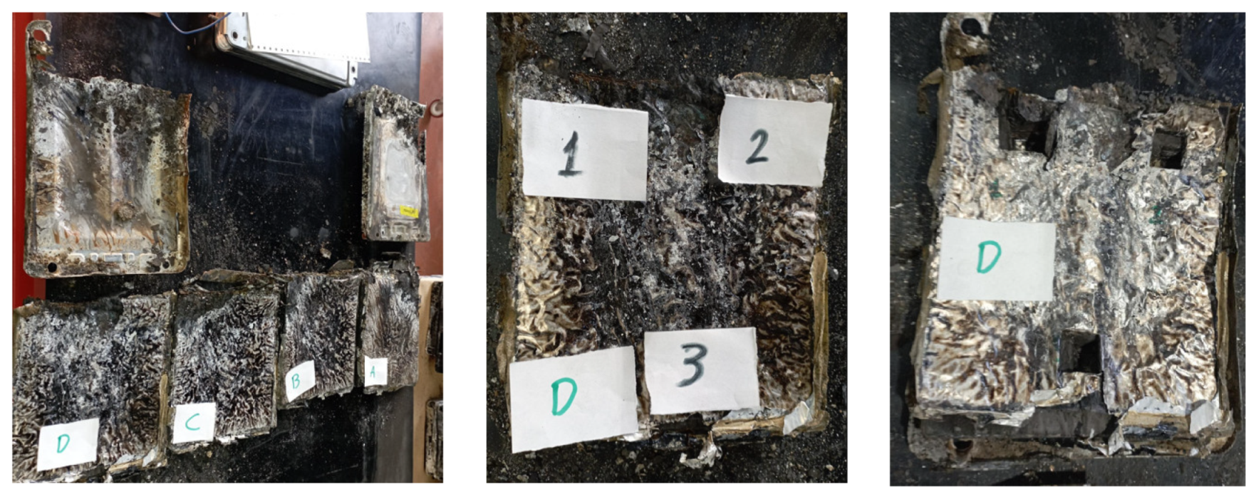
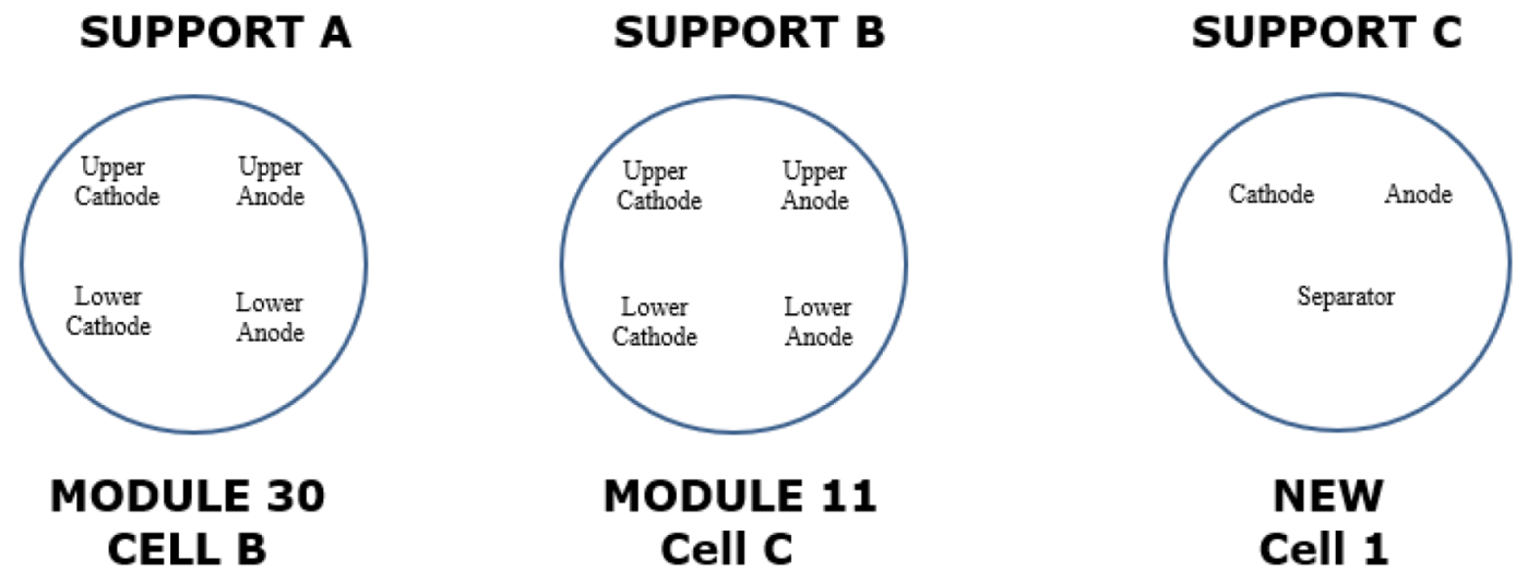
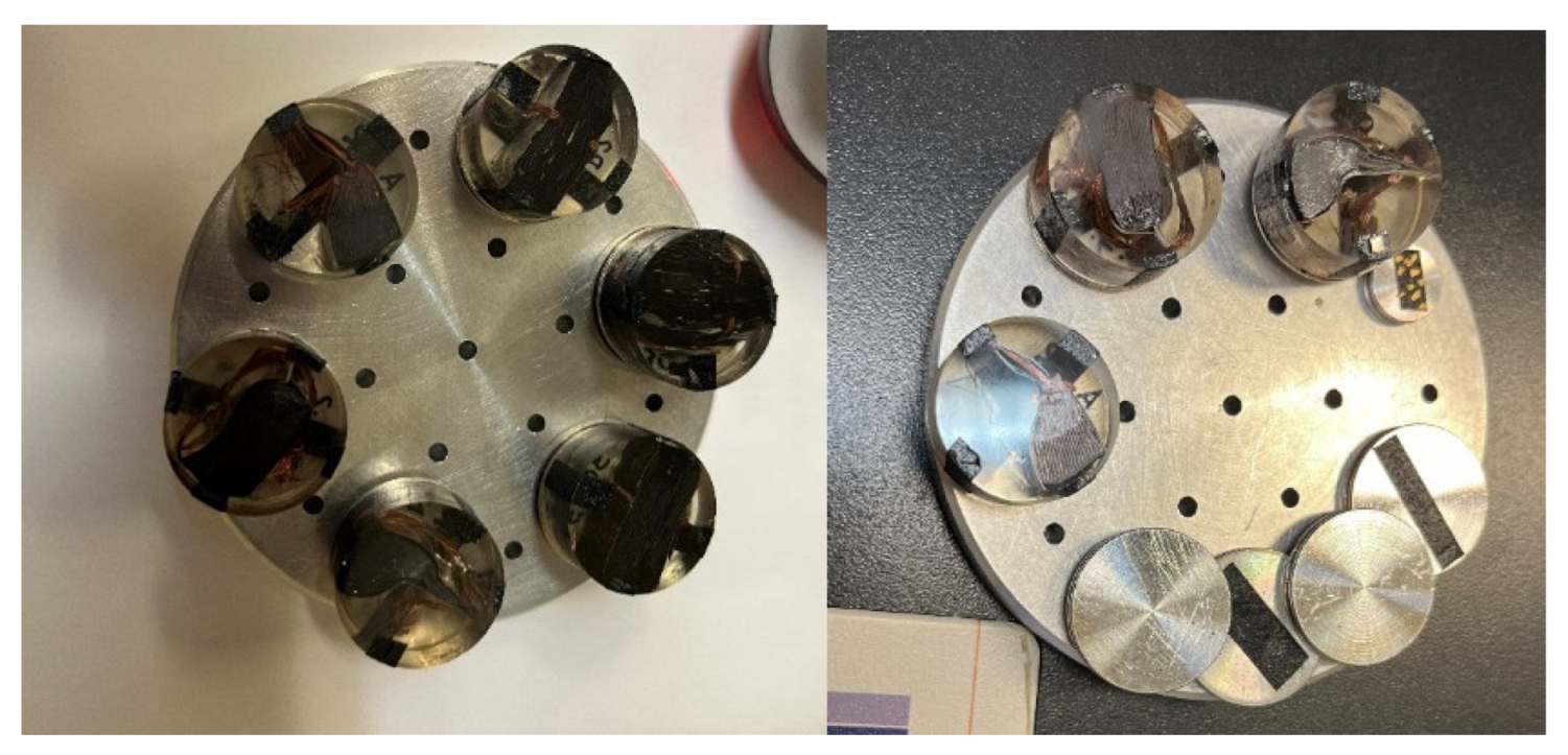
To carry out the surface analysis tests, three aluminium supports are prepared, support A, support B and support C. Two cathode samples, one from the upper cathode and one from the lower cathode, and two anode samples, one from the upper anode and one from the lower anode, are prepared in the support A from cell B of module 30, see
Figure 18. Two cathode samples, one from the upper cathode and one from the lower cathode, and two anode samples, one from the upper anode and one from the lower anode, are prepared in support B from cell C of module 11, see
Figure 18. And in support C, a sample of the cathode, anode and separator of a new Nissan Leaf cell is prepared.
Figure 17.
View of sample preparation for surface testing.
Figure 17.
View of sample preparation for surface testing.
Figure 18.
Arrangement of samples from different cells for surface analysis.
Figure 18.
Arrangement of samples from different cells for surface analysis.
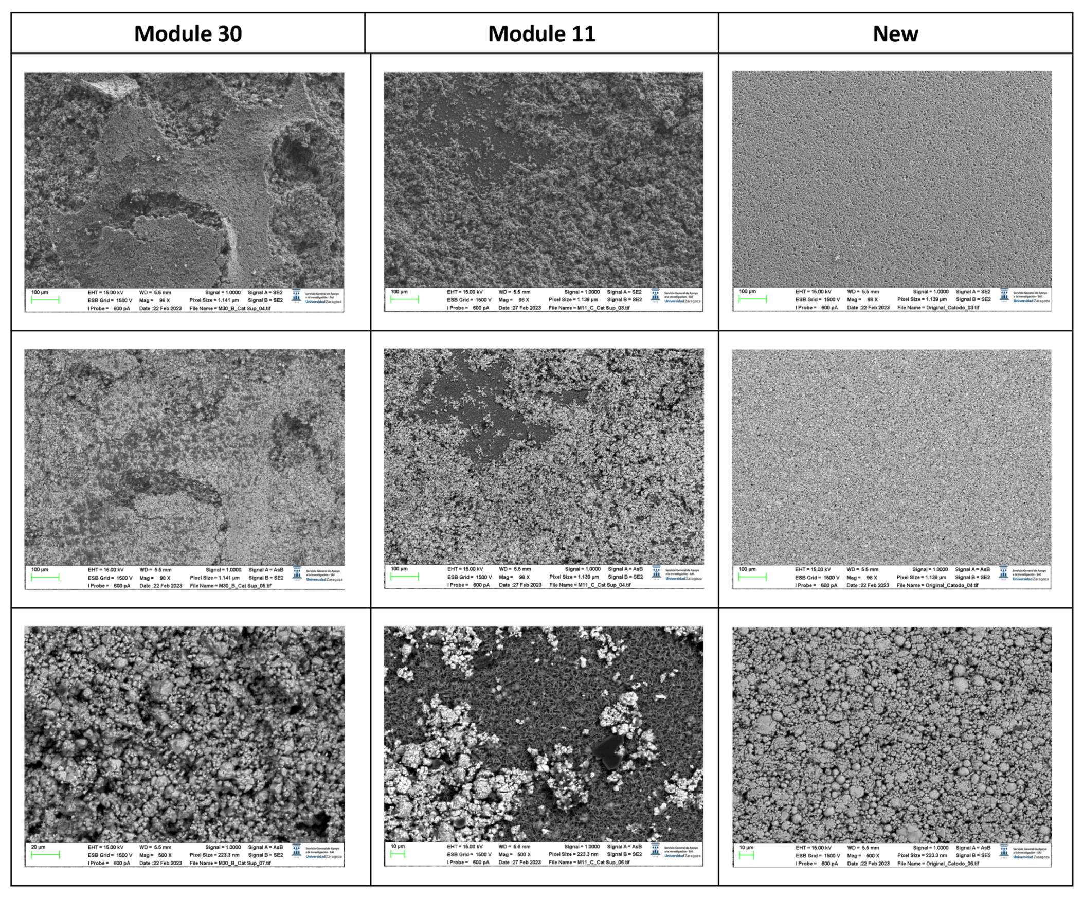
The following images compare different pictures obtained with FESEM of the upper cathode of module 30, module 11 and the new cell.
Figure 19.
Comparison of images obtained with the FESEM of different areas of the upper cathode of module 30, module 11 and the new cell.
Figure 19.
Comparison of images obtained with the FESEM of different areas of the upper cathode of module 30, module 11 and the new cell.
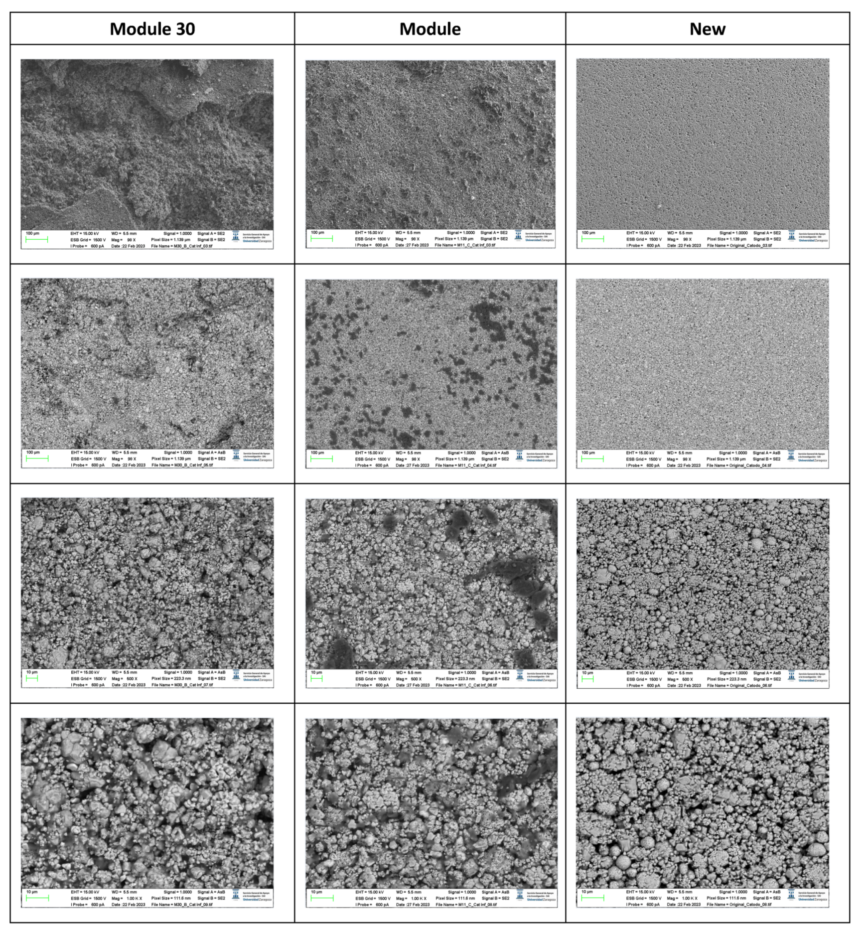
The following images compare different images obtained with FESEM of the lower cathode of module 30, module 11 and the new cell.
Figure 20.
Comparison of images obtained with the FESEM of different areas of the lower cathode of module 30, module 11 and the new cell.
Figure 20.
Comparison of images obtained with the FESEM of different areas of the lower cathode of module 30, module 11 and the new cell.
With respect to the cathode electrodes in the figure above, the cathode of an original cell has been compared with two cathodes (one upper and one lower) of module 30 and module 11 of the battery of the burning Nissan Leaf, after experiencing the Thermal Runaway. It should be noted that rather than a single particle size, most materials, especially the active materials used in battery electrodes, contain a variety of particle sizes.
It is noted that after experiencing the Thermal Runaway phenomenon, the cathode surface is covered with off-white floccules. The distribution of these floccules on the surface of the cathode electrodes is not uniform, being more concentrated in one area and more dispersed in another area.
Due to the morphology of these substances, it can be deduced that they are decomposed separators due to the high temperature, since at 150 ºC the separator shrinks and groups together. In other words, after TR the separator decomposes as the temperature increases.
The decomposition temperature of a PE-PP-based polymer is greater than 300 °C. Therefore, it is reasonable for the surfaces of the cathode electrodes to be covered with unevenly distributed separator particles.
It should be noted that the burned modules being analysed had 68% SoC (State of Charge). As SoC increases, the number of flocs increases greatly and darker coloured and spherical flocs appear, indicating that having an elevated SoC, the reaction temperature inside the cell is higher during TR, and the agglomeration and decomposition reactions of the separators are more intense [
36].
The spherical cluster structure of the cathode active materials and the flake structure of the graphite have been destroyed after TR. The cathode and anode are joined together, and it is quite difficult to identify them. There are also irregularly shaped impurities/debris, some rectangular and some spherical, and chaotically distributed. When the temperature is increased due to the TR, the aluminium current collector of the chaotic electrode had oxidized and adhered to the anode side.
Therefore, it is normal to observe in the cathode traces of fragments of cathode materials after TR, ash from the cathode material and separators, products of exothermic reactions and graphite peels.
It is observed that in the case of module 11 there are more dark-coloured flocs than in the case of module 30, and there are more in the upper cathode than in the lower cathode. Therefore, it is concluded that module 11, in vertical arrangement, experiences higher temperature in the TR at the same SoC as module 30, which is in horizontal arrangement. If the structural transformation (morphology analysis with InLens) of the cathode materials after the TR is analysed (
Figure 21 and
Figure 22) it is observed that in the case of modules 30 and 11 with a SoC of 68% after the TR, the layered structure of the material was destroyed, the particles dispersed outside the original layered structure and adhesion occurred. The positive electrode material (cathode) reacted at high temperature and decomposed. On the other hand, carbon particles from the negative electrode (anode) were doped into the positive electrode (cathode) through the damaged diaphragm.
It is observed that in the case of the lower cathode of module 30 (horizontal arrangement) the particles are smaller compared to the upper cathode of module 30, this may be due to the higher temperature as it is more exposed.
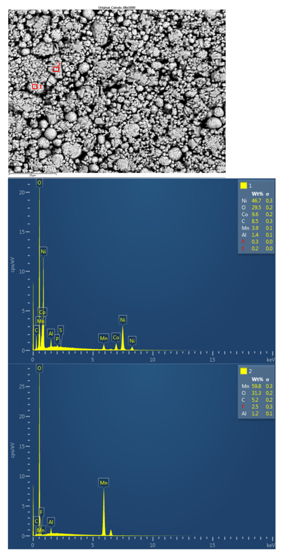
In the case of module 11 (vertical arrangement) there is no difference between the particle size of the upper cathode and the lower cathode. Hereafter, the chemical composition analysis of the upper cathode of module 30 and module 11 will be presented in comparison to the composition of the original cathode. The cathode showed a granular surface structure as can be seen in the following image (
Figure 23). The largest particles were about 6 μm in size. The following chemical elements were identified by EDXS: manganese (Mn), cobalt (Co), nickel (Ni), oxygen (O), and carbon (C). This led to the conclusion of a LiNiMnCoO
2 (NMC) cathode chemistry. Two different types of structures were observed on the cathode surface, marked in
Figure 24 by two red boxes. The results of a detailed analysis of the formed compounds show that the compound marked with "1" had the NMC chemistry mentioned above, while the second structure was determined to be a manganese oxide compound (LMO), some fluorine was also observed that may be from the electrolyte (LiPF6) when in contact with the cathode and anode. Considering these issues, cathode layer chemistry could be established as a mixture of NMC and LMO.
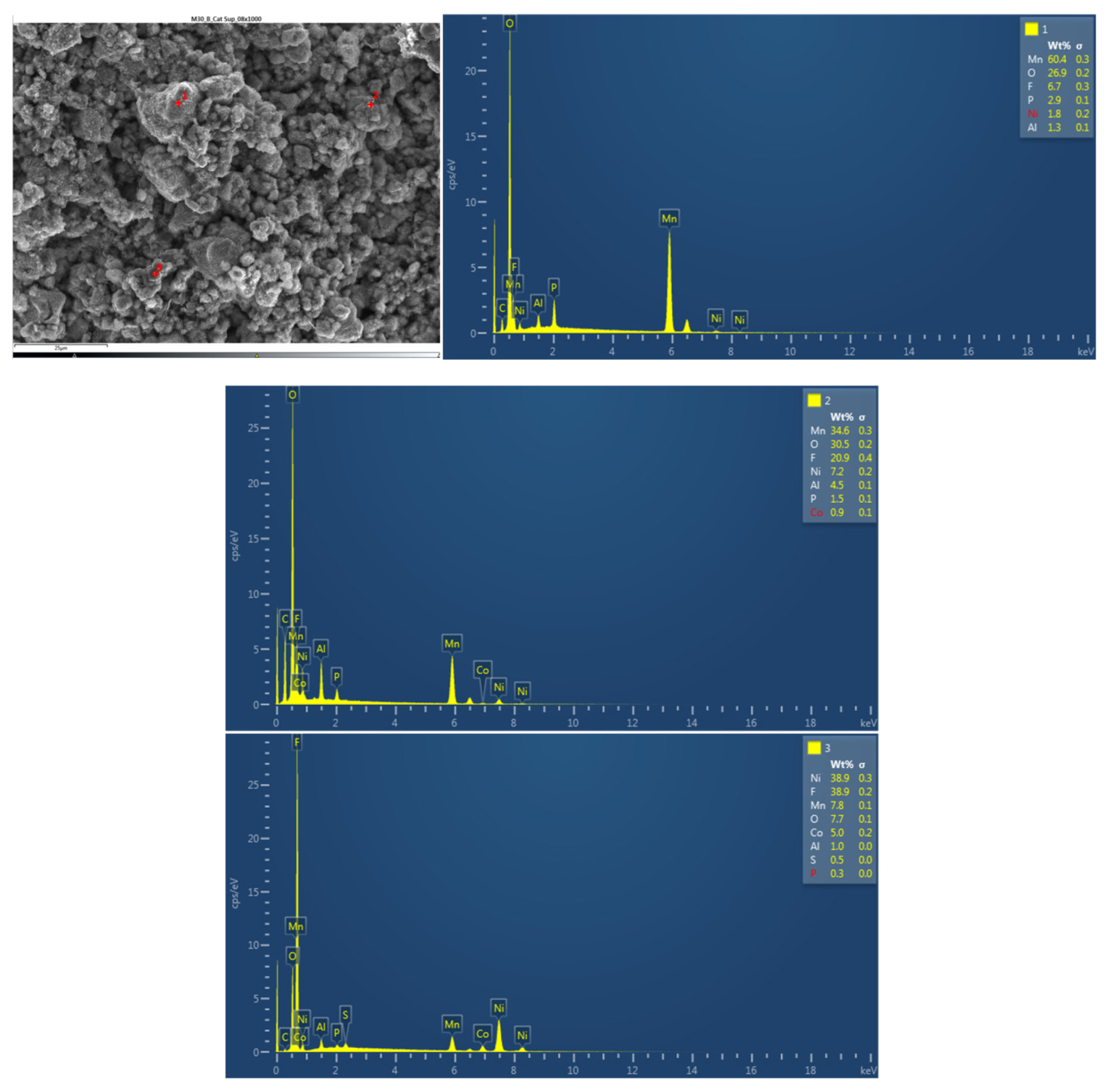
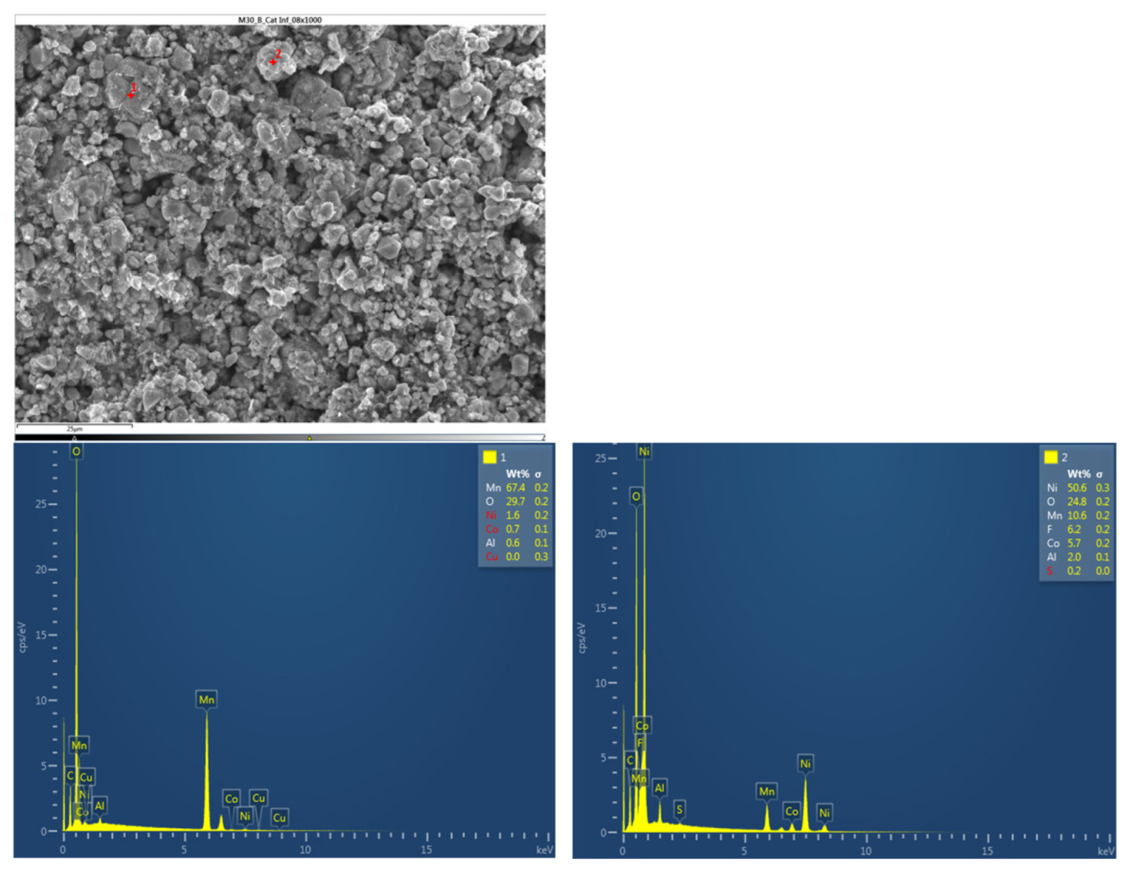
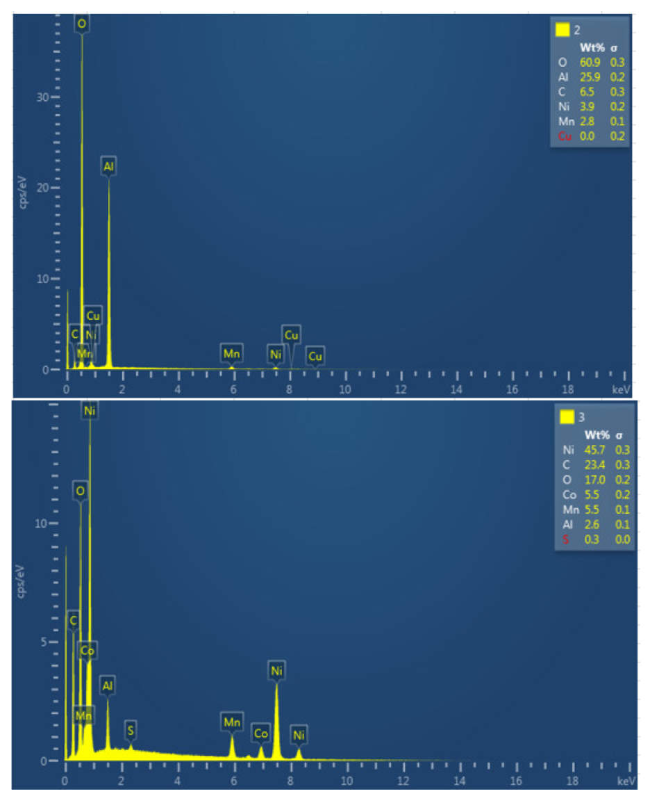
Next, the chemical composition of the upper cathode of the ignited module 30 is analyzed. The upper cathode of module 30 no longer shows a defined granular surface as in the case of the original cathode, the structure has been broken. The largest particles are about 5 μm in size. The following chemical elements were identified by EDXS: manganese (Mn), cobalt (Co), nickel (Ni), oxygen (O), fluorine (F), phosphorus (P), carbon (C) and aluminum (Al). Three different structural types were observed on the cathode surface of module 30, marked in
Figure 24 by three red crosses. The results of a detailed analysis of the formed compounds show that the compound marked with "1" had the chemistry of a compound with manganese and oxygen and some fluorine and phosphorus, while it was determined that the second structure was also a manganese and oxygen compound, more fluorine was observed than in the previous compound, was observed also nickel and aluminum. And finally in the rectangular shaped compound "3" it was observed fluorine and nickel. This last compound is due to the reactions that have taken place in the TR and that is why there are leftover of the electrolyte.
Figure 24.
Chemical composition of the upper cathode of module 30.
Figure 24.
Chemical composition of the upper cathode of module 30.
Next, the chemical composition of the lower cathode of the ignited module 30 is analyzed. The lower cathode of module 30 also does not show a defined granular surface as in the case of the original cathode, the structure has been broken. The larger particles are about 4 μm in size, so the particles are smaller than in the case of the upper cathode of the same module, probably because they have been exposed to higher temperature values. Two different types of structures were observed on the surface of the lower cathode of module 30, marked in
Figure 25 with two red crosses. The results of a detailed analysis of the compounds formed show that the compound marked with "1" had the chemistry of a compound with oxygen and manganese, while it was determined that the second structure was also the chemistry of a nickel and oxygen compound, some manganese, fluorine, cobalt, and aluminum were also observed.
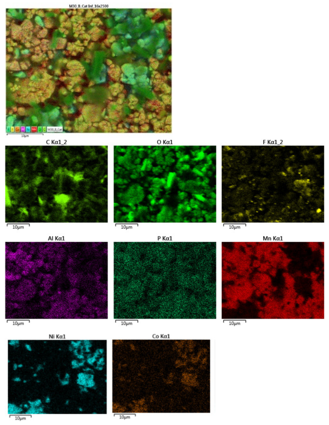
The distribution of elements in each area of the upper cathode of module 30 is also mapped. This information is also collected with the EDS detector and then processed with the AZtec software.
Figure 26.
Distribution of elements in each area of the upper cathode of module 30.
Figure 26.
Distribution of elements in each area of the upper cathode of module 30.
Below is a map of the distribution of elements in each area of the lower cathode of module 30.
Figure 27.
Distribution of elements in each area of the lower cathode of module 30.
Figure 27.
Distribution of elements in each area of the lower cathode of module 30.
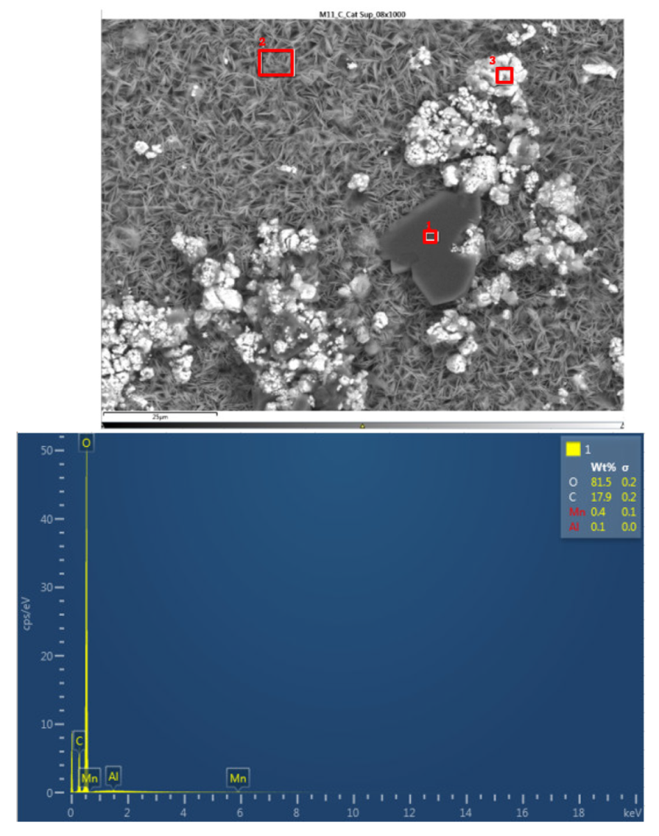
In the lower cathode there is a higher amount of fluorine, aluminum, manganese, phosphorus, nickel, and cobalt than in the upper cathode. The following figure shows the chemical composition of the upper cathode of modulo 11. The upper cathode of module 11 also does not show a defined granular surface as in the case of the original cathode, the structure has been broken. The larger particles are about 5 μm in size, so the particles are smaller than in the case of the original cathode. Three different types of structures are observed on the surface of the upper cathode of modulo 11, marked in
Figure 28 with three red squares.
The results of a detailed analysis of the formed compounds show that the compound marked with "1" had the chemistry of a carbon and oxygen compound, while the second structure was determined to be an aluminum and oxygen compound, formed from the fusion of the cathode aluminum collector, and the third structure was a nickel, carbon, oxygen, cobalt, manganese, and aluminum- containing chemical compound. They are all elements that are products of the cathode and collector coating. Regarding module 11, a higher amount of aluminum is observed, this may be since in this case the aluminum collector has been more damaged than in the case of module 30.
The following figure shows the chemical composition of the lower cathode of module 11. The lower cathode of module 11 also does not show a defined granular surface as in the case of the original cathode, the structure has been broken. Five different types of structures are observed on the surface of the lower cathode of module 11, shown in
Figure 29. The results of a detailed analysis of the compounds formed show that the compound marked with "1" had peaks of nickel, manganese, oxygen, copper, carbon, cobalt, and fluorine, so it presents all the elements of the cathode coating, there is also copper that can come from the anode collector. The second structure was a compound of nickel, manganese, cobalt, oxygen, and carbon, and the third structure was compound of copper and oxygen, probably because the anode collector has melted. If compound 4 is analyzed, it is a nickel, oxygen, manganese, and fluoride-containing chemical compound. And finally, compound 5 is a manganese and oxygen compound, formed from the active material of the cathode, and there is also aluminum coming from the aluminum collector of the cathode. In this area appears an aluminum peak this is the result of thermal failure that leaves the aluminum current collector exposed.
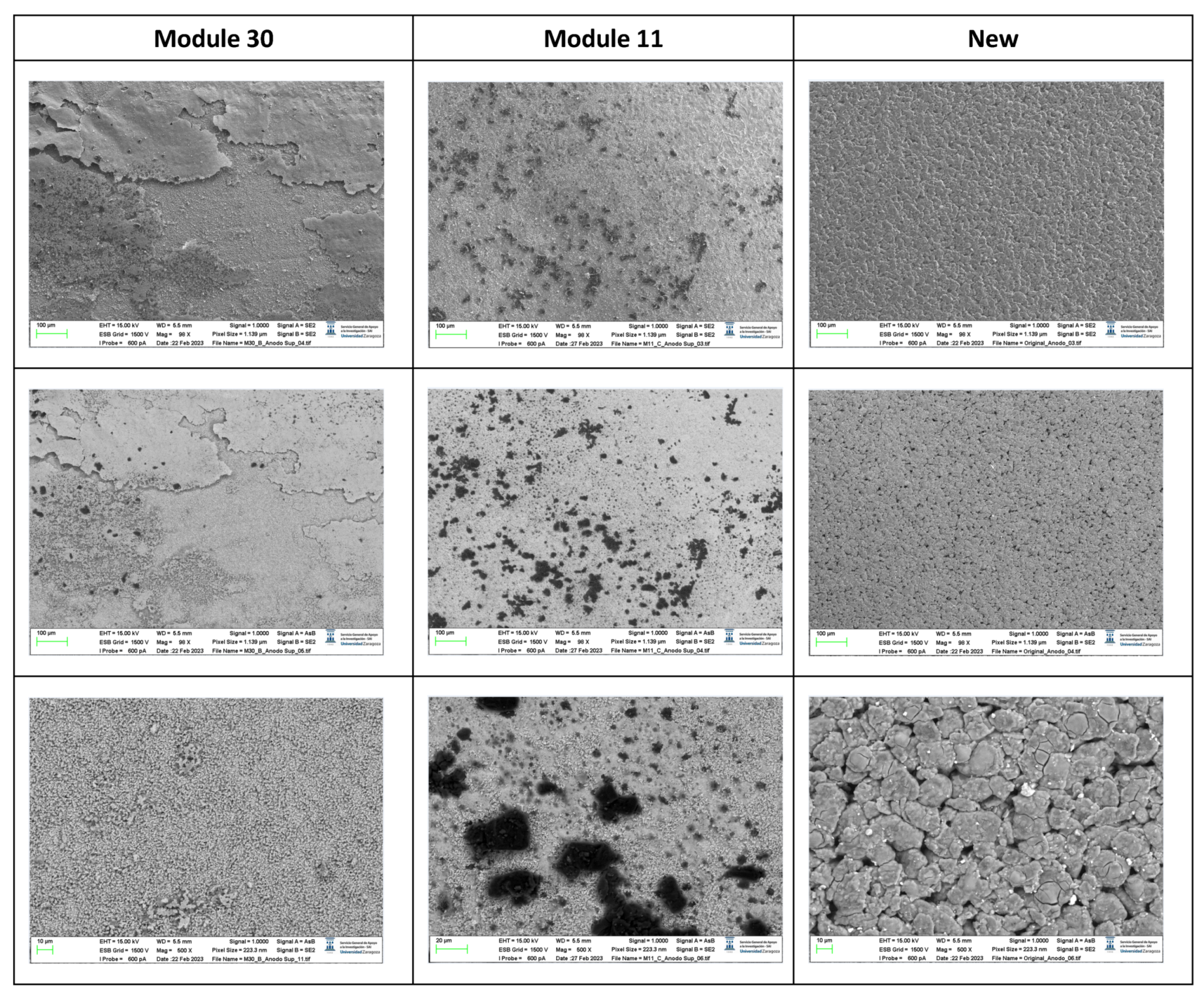
The following images compare different images obtained with FESEM of the upper anode of module 30, module 11 and the new cell. And in the
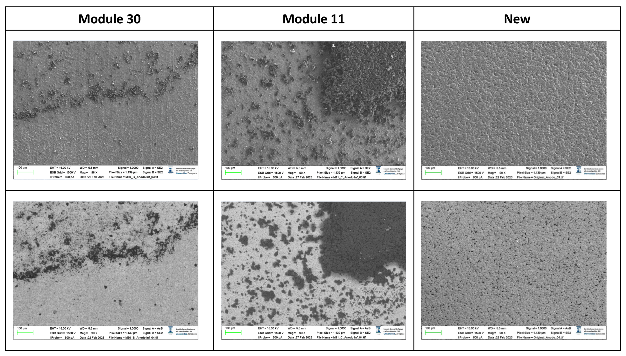
Figure 31, it is compared different images obtained with FESEM of the lower anode of module 30, module 11 and new cell.
Figure 30.
Comparison of images obtained with the FESEM of different areas of the upper anode of module 30, module 11 and the new cell.
Figure 30.
Comparison of images obtained with the FESEM of different areas of the upper anode of module 30, module 11 and the new cell.
Figure 31.
Comparison of images obtained with the FESEM of different areas of the lower node of module 30, module 11 and the new cell.
Figure 31.
Comparison of images obtained with the FESEM of different areas of the lower node of module 30, module 11 and the new cell.
With respect to the anode electrodes in the previous figure, as it has been done with the cathode electrodes, the anode of an original cell with two anodes (one upper and one lower), it has been compared with module 30 and module 11 of the battery of the burning Nissan Leaf, i.e., after experiencing the Thermal Runaway. It is observed that after experiencing the Thermal Runaway, that spherical particles exist on the surface of the graphite anode. These spherical surfaces are covered with smaller stereoscopic particles as can be seen in
Figure 30 and
Figure 31.
The original graphite anode has a porous structure that disappears when it undergoes a TR because the pores are occupied by spherical particles. The formation of stereoscopic particles is related to the exothermic reaction on the anode side when TR occurs. On the other hand, at higher temperatures, the intercalated carbon can react with the electrolytes to form Li
2CO
3 [
31] since at a temperature above 120 °C the SEI decomposes. In addition, as the temperature increases, at approximately 290 °C, the lithiated carbon could react with fluorine to form LiF [
31].
After the analysis of the state of the cathode and anode after experiencing the TR, it is concluded that the spherical structure of the active materials of the cathode and the flake structure of the graphite are destroyed. To obtain the sample from the ignited modules, the cathode and anode were joined together, and it was quite difficult to identify them.
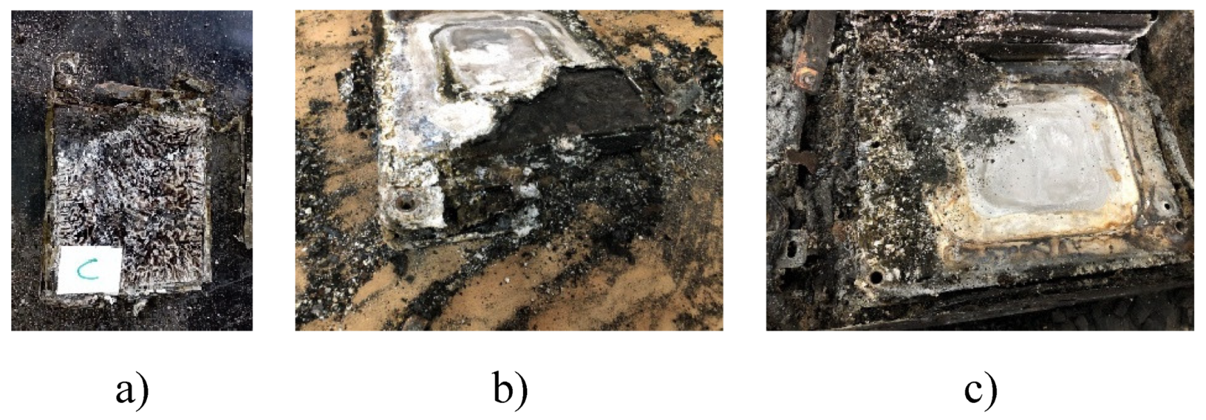
Figure 32.
a. Cell c of module 30, b. Module 11 set on fire, c. Module 30 burned down.
Figure 32.
a. Cell c of module 30, b. Module 11 set on fire, c. Module 30 burned down.
It is observed that there are many impurities on the surface of the electrode. The shape of these impurities is not regular. Sometimes it is rectangular and sometimes it is spherical. The surface distribution is chaotic as can be seen in
Figure 32b,c. Because the temperature at which TR is reached in NMC pouch cells is high, the aluminum current collector of the cathode electrode is oxidized and bonded to the anode. Therefore, it is normal to observe debris in the image observed with the SEM. Studies [
30] indicate that these debris can be fragments of cathode materials, cathode and separator ash, products of exothermic reactions, as well as graphite flaking. In some areas, a dense and brittle layer has been found on the surface of the electrode. In other areas, flake graphite particles were found under this layer. Thus, it follows that this layer was a completely oxidized aluminum current collector. Unlike in the cathode, the pores of the anode have been clogged by materials from TR reactions. In some areas, a dense, brittle layer covering the surface of the electrode is also observed. In other areas, flake graphite particles were observed under this layer. Therefore, the authors speculated that this layer was a completely oxidized Al current collector. Judging by the structure of the base layer, it was the layer of active material on the anode. Unlike the active material coating of the cathode of new cells, the pores of the electrode that suffered thermal runaway had been completely clogged by the products of the thermal runaway reactions. The active material of the cathode had completely ceased to function. If the structural transformation (morphology analysis with InLens) of the anode materials after the TR is analyzed (
Figure 33 and
Figure 34) it is observed that in the case of modules 30 and 11 with a SoC of 68% after the TR, the layered structure of the material was destroyed, the particles dispersed outside the original layered structure and adhesion occurred. The positive electrode material (cathode) reacted at high temperature and decomposed. On the other hand, carbon particles from the negative electrode (anode) were get into the positive electrode (cathode) structure through the damaged diaphragm.
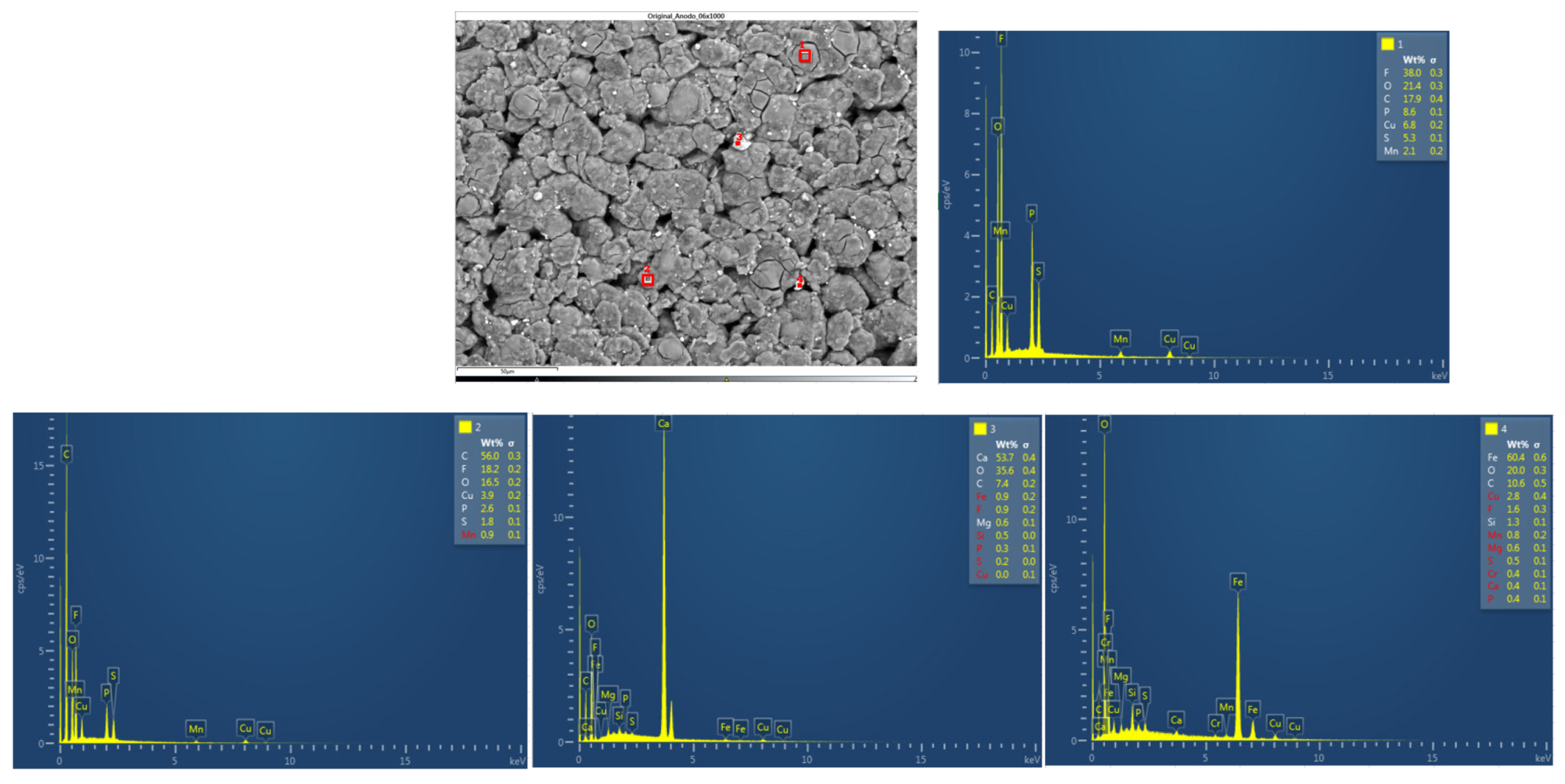
The chemical composition of the new cell anode is then analyzed. The anode has a granular structure. The diameter of the largest particles was 14 μm. Four types of structures are identified. The results of the chemical analysis revealed a high content in zone 2 of carbon (C), which allows the active material of the anode to be identified as graphite. There are traces of phosphorus (P) that can be identified as remnants of the electrolyte (assumed to be LiPF6 dissolved in a carbonate mixture solvent). Also, in zone 1 a fluorine peak is identified, it can be seen on the surface of the graphite particles and can be attributed to the decomposition of the electrolyte that is part of the SEI. The small peaks of Cu can be attributed to the preparation of the sample and can be neglected. On the other hand, in zones three and four, peaks of calcium and iron are identified, due to the shape of which impurities can be considered that have appeared due to the preparation of the sample. Manganese also appears.
Figure 35.
Chemical composition of the new cell anode.
Figure 35.
Chemical composition of the new cell anode.
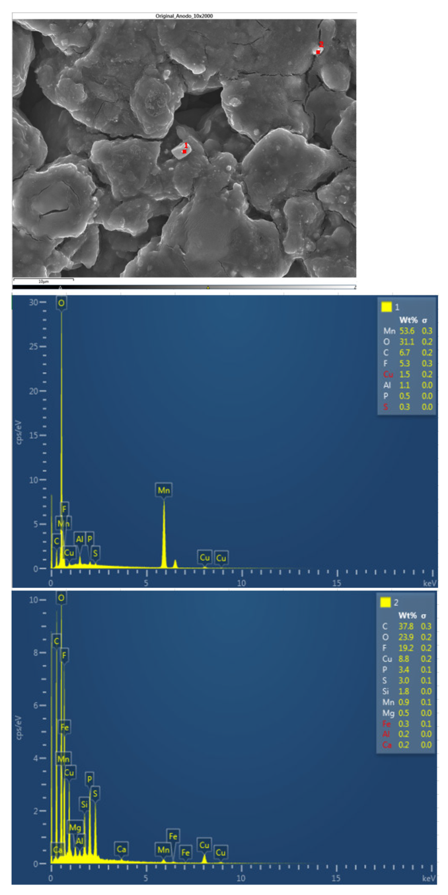
The following figure shows the chemical composition of other structures identified in the original anode. Structure 1 identifies a chemical compound of manganese and oxygen, and structure 2 identifies a chemical compound of carbon and oxygen with fluorine, which may be due to electrolyte, copper, phosphorus, and sulfur (the latter three elements may be due to impurities from sample preparation).
Figure 36.
Chemical composition of the new cell anode 2.
Figure 36.
Chemical composition of the new cell anode 2.
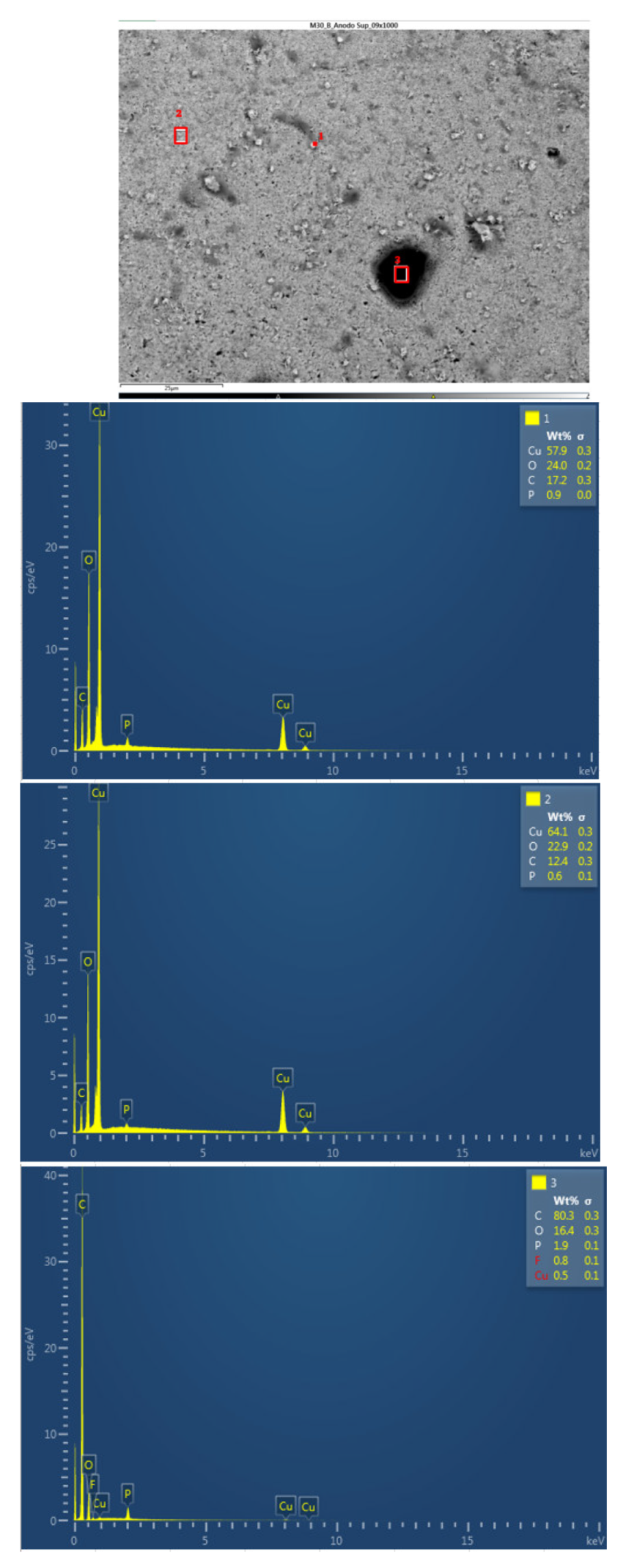
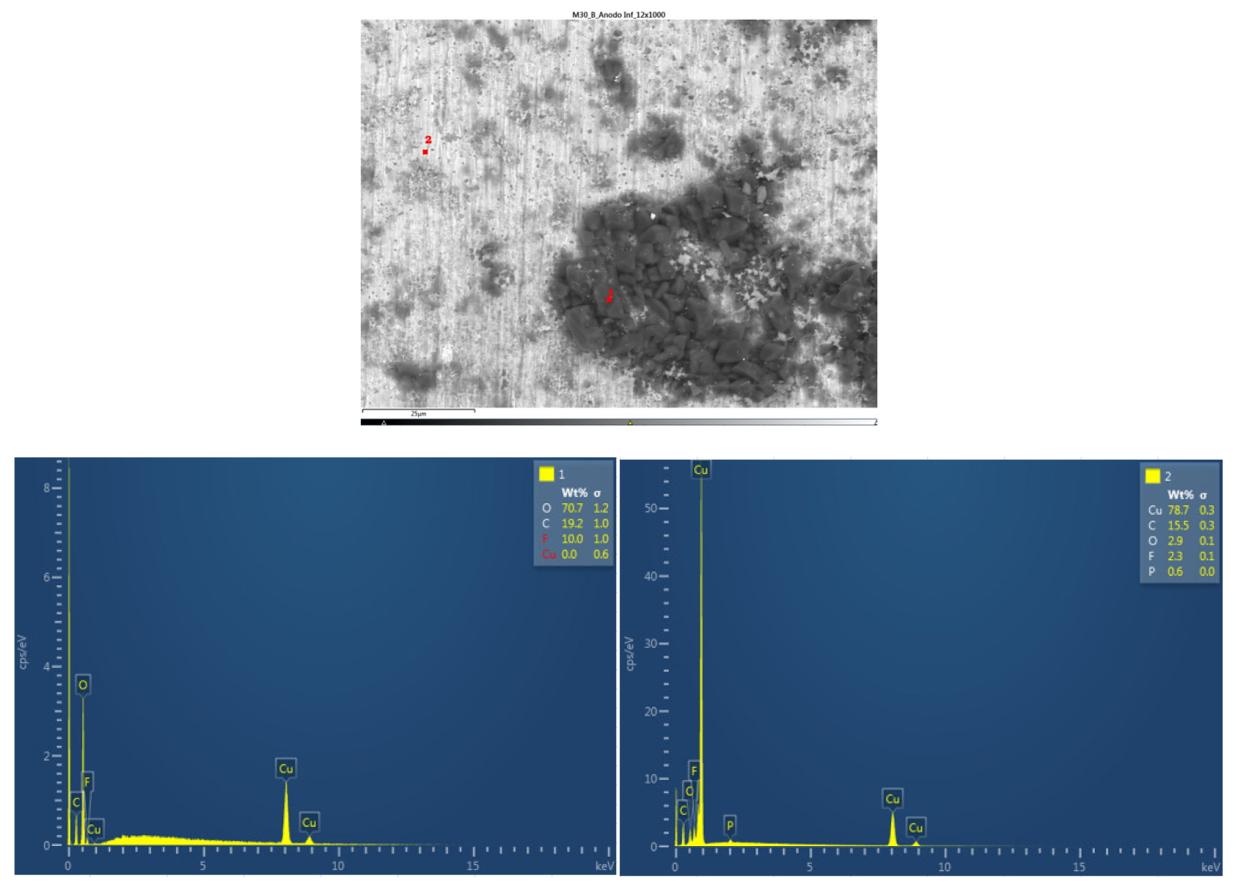
Afterwards, the chemical composition of the upper anode of the ignited module 30 is analyzed. The upper anode of module 30 also does not show a defined granular surface as in the case of the original anode, the structure has been broken. Three different types of structures were observed on the surface of the upper anode of module 30, shown in
Figure 37. The results of a detailed analysis of the compounds formed show that the compound marked with "1" had the chemical of a copper and oxygen compound, which may be due to the anode collector having melted due to the elevated temperatures, and the second structure was also identified as a copper and oxygen compound, while structure 3 was a carbon and oxygen compound, it may be due to the coating of the graphite anode.
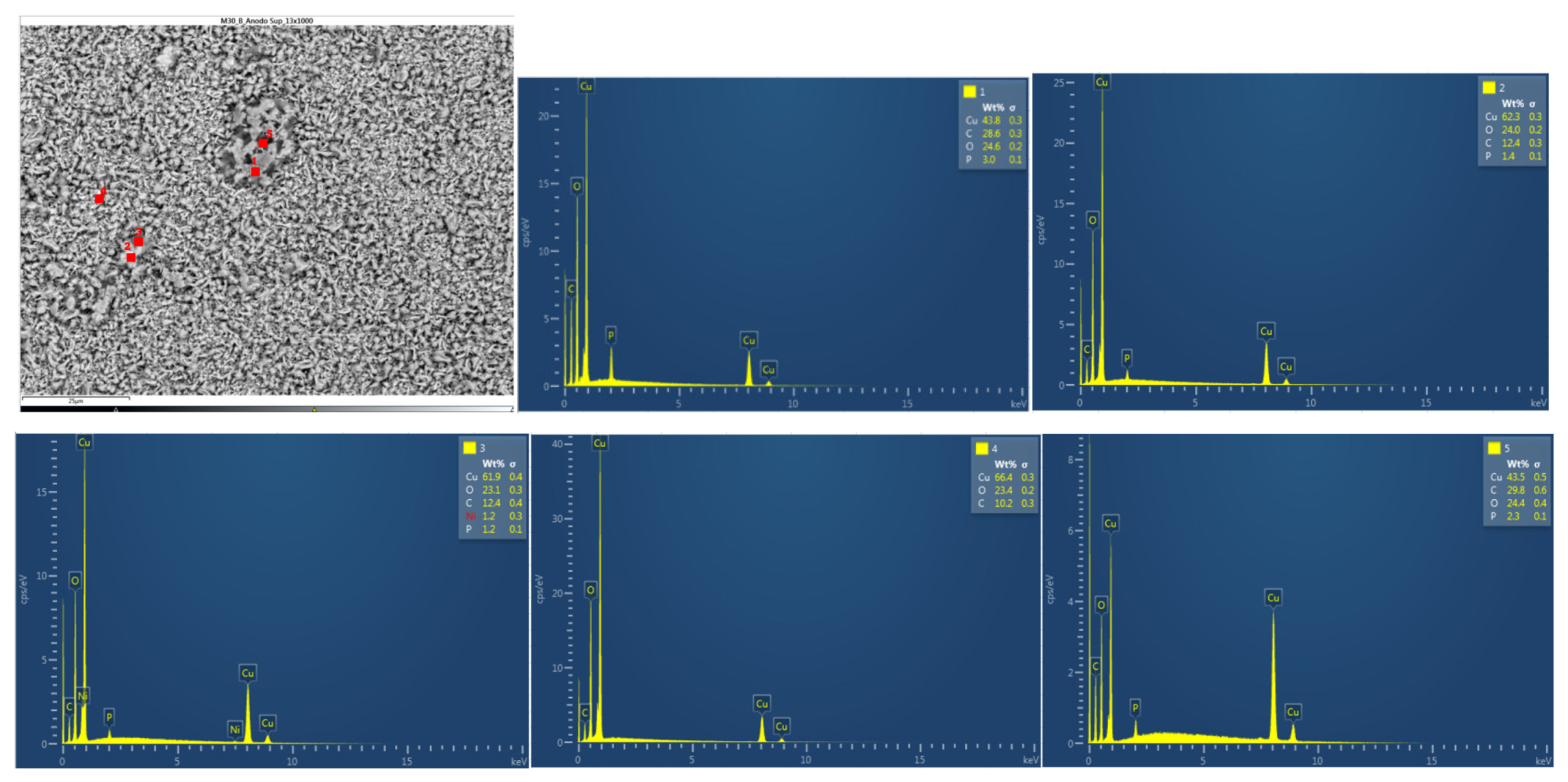
In
Figure 38 below, the chemical composition in another area of the upper anode of the ignited module 30 is analyzed. Five different types of structures were observed on the surface of the upper anode of module 30. All five structures feature copper, carbon, and oxygen.
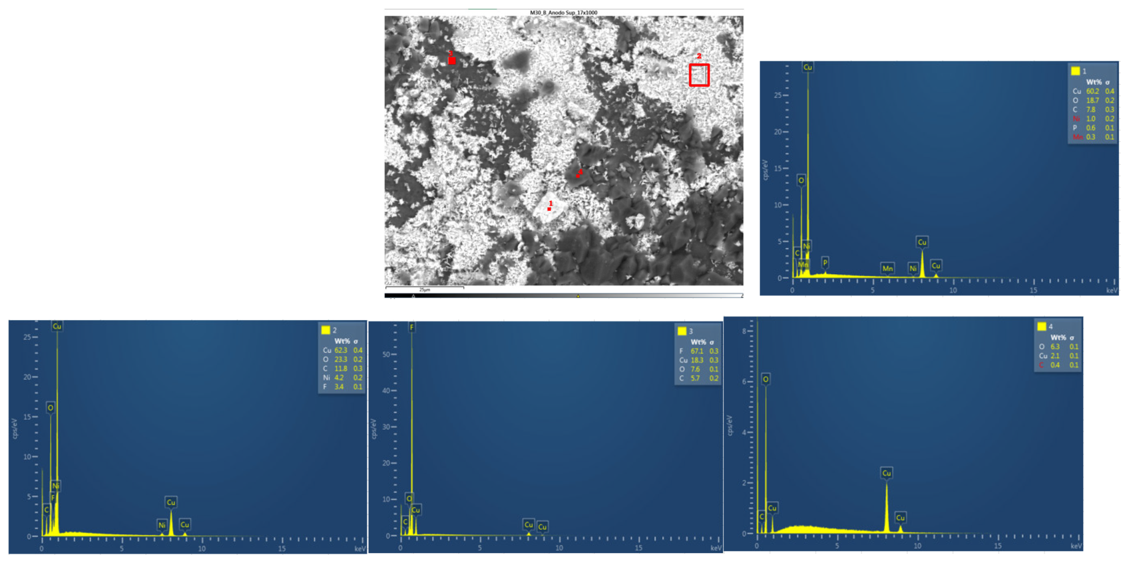
In
Figure 39 below, the chemical composition in another area of the upper anode of the ignited module 30 is analyzed. Four different types of structures were observed. In the first three ones a compound of copper, carbon and oxygen was observed. In zone 4, fluoride, copper and oxygen were identified, the existence of fluoride is due to the electrolyte and the existence of copper is due to copper from the anode collector.
Next, the chemical composition of the lower anode of the ignited module 30 is analyzed. The lower anode of module 30 also does not show a defined granular surface as in the case of the original anode, the structure has been broken. Two different types of structures were observed on the surface of the lower anode of module 30, shown in
Figure 40. The results of a detailed analysis of the compounds formed show that the compound marked with "1" had the chemistry of a Carbon and oxygen compound, which may be due to the anode coating, and the second structure features copper, carbon, and oxygen.
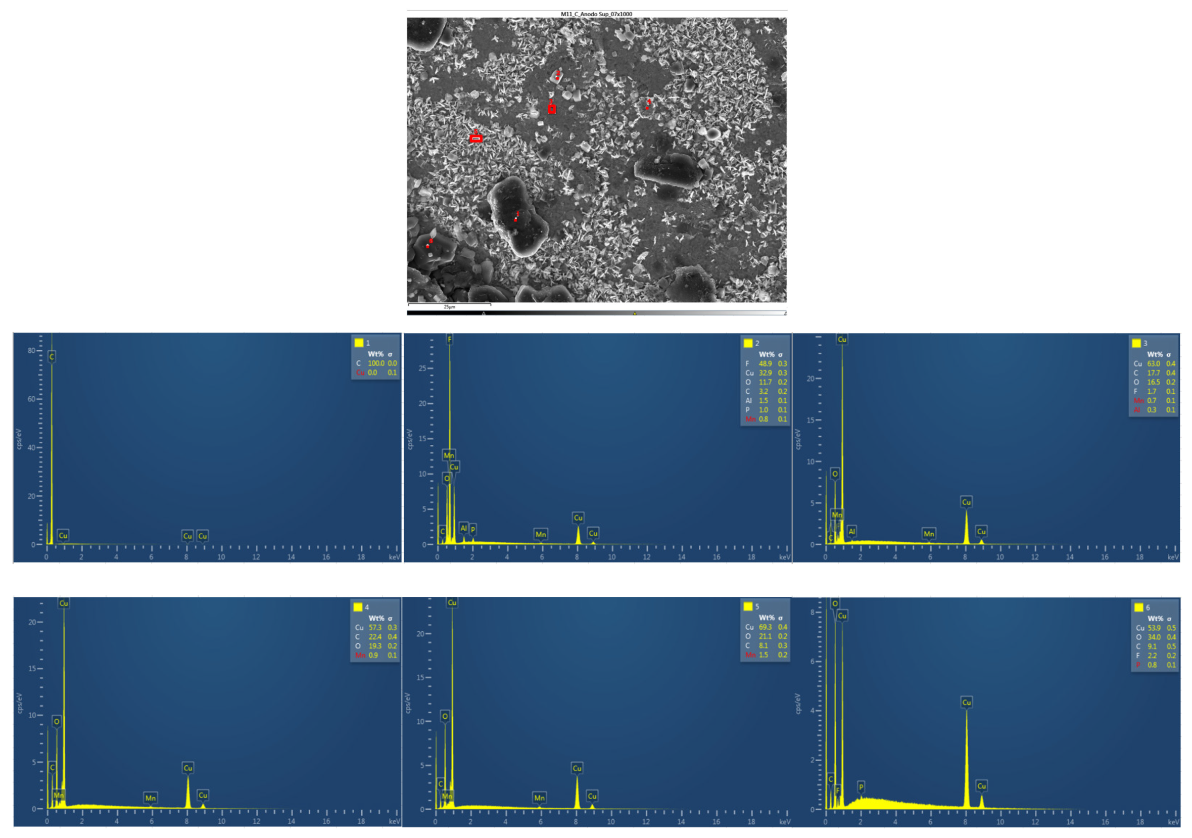
Figure 41 below shows the chemical composition in another area of the upper anode of the ignited module 11. Six different types of structures were observed on the surface of the upper anode of module 11. The first structure is carbon, coming from the graphite of the anode coating, the second structure was a compound of fluorine, copper and oxygen, fluorine comes from the electrolyte, the rest of the structures have copper, carbon, and oxygen.
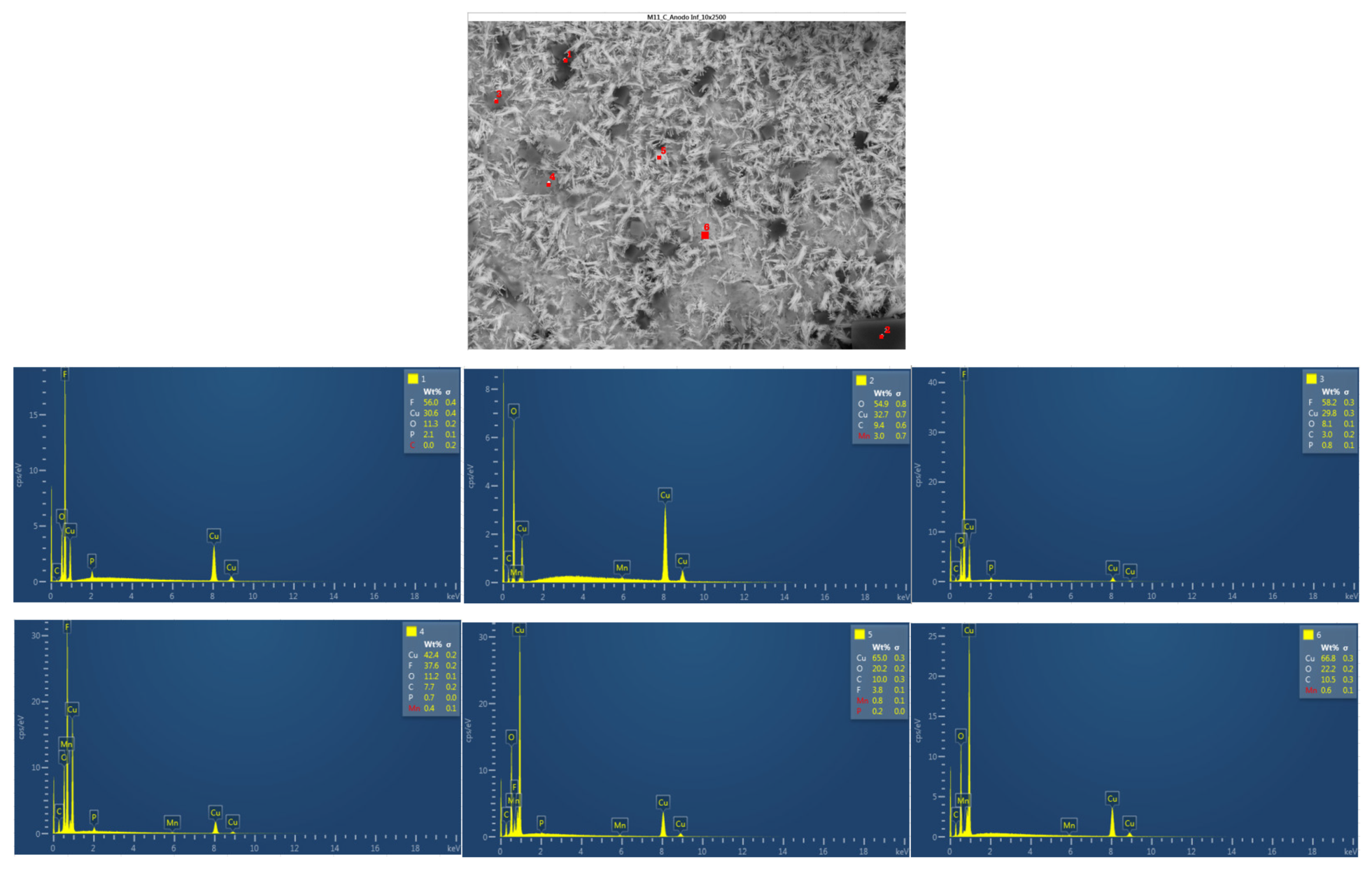
And finally, in the following
figure 42, the chemical composition in another area of the lower anode of the burning module 11 is analyzed. Six different types of structures were observed on the surface of the lower anode of module 11. The first structure was a compound of fluorine, copper, and oxygen, in structure 2 was identified copper and oxygen, structure 3 is like the first, a compound of fluorine, copper and oxygen. In structure 4 there is more copper than fluorine and oxygen, and in structures 5 and 6, there is copper oxide and carbon oxide.
The analysis of the cell anodes after the fire test, shows that the anode has peaks of oxygen and peaks of carbon, which indicates the formation of lithium carbonate (Li2CO3).
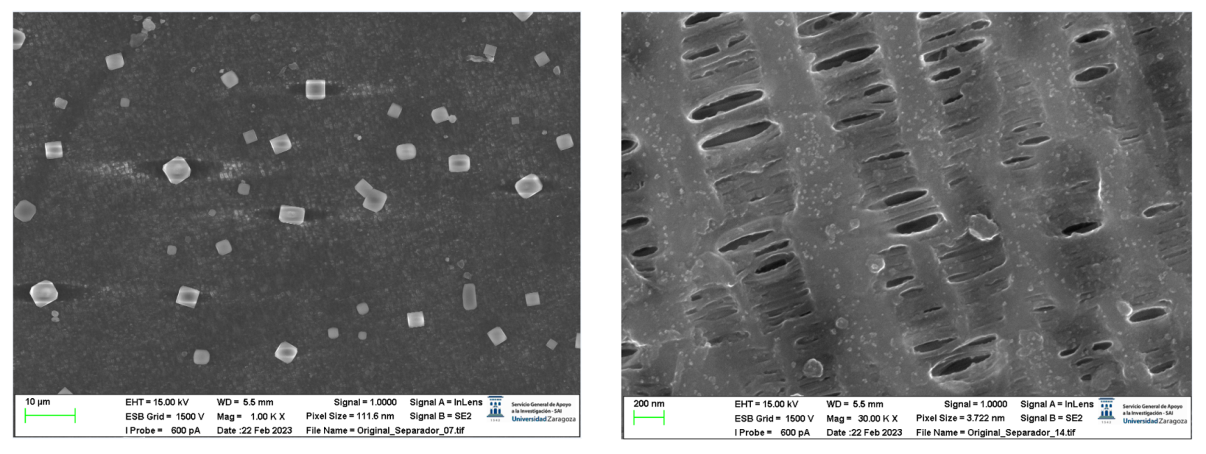
A morphological analysis of the separator of the new cell is then performed since the separator cannot be recovered in the burned modules because it has melted in the thermal runaway reaction. The surface structure of the separator was investigated to determine the thickness of the separator fibers and the size of the pores, as well as to determine whether an alumina layer had been deposited on the separator membrane, as indicated above.
Figure 43 shows the results of the SEM image. On the right is shown the structure of the fibers of the polypropylene membrane, (C3H6)n. The separator fibers were aligned in a direction perpendicular to the cell tabs.
The total thickness of the separating fiber was about 289 nm, as shown in
Figure 44. The analyzed structure shows pores of different diameters, the smallest of about 41.61 nm and the largest about 88.78 nm. A general requirement for pore size in lithium-ion cells is that they must be in the submicron range to prevent dendritic penetration of lithium from occurring over the life of the battery [
37].
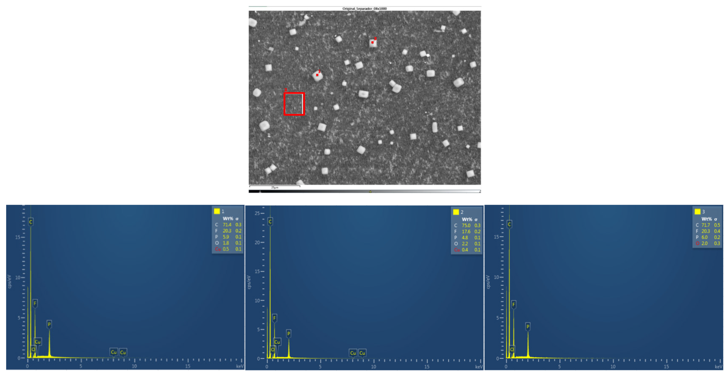
After that, the analysis of the chemical composition of the separator will be performed. There are three types of structures, the first being carbon with fluorine and phosphorus. The carbon is from the structure of the polypropylene separator itself; the fluorine comes from the electrolyte with which it is soaked, and the phosphorus may be due to an impurity in the preparation of the sample. Structure 2 and 3 have the same composition as the first structure.
Figure 45.
Chemical composition of the separator.
Figure 45.
Chemical composition of the separator.
The layered structure was destroyed when the thermal runaway occurred. In the battery sample with 68% SoC, there were characteristic fluoride peaks, indicating that the cathode material reacts with the electrolyte after decomposition [
38]. Characteristic carbon peaks are also shown, this is because, in the Thermal Runaway reaction, some of the carbon dust was get into the positive electrode material through the broken diaphragm [
39]. It is observed that in the samples of module 11 and module 30, in which a Thermal Runaway reaction has occurred, the structure of the positive electrode (anode) sample is destroyed, and the particles were dispersed outside the original stratified structure, and the adhesion phenomenon occurred, showing fragmentation. Particles cannot be found, and external impurities are placed inside the structure [
40].
The battery that caught fire in the test had 68% SoC. There are studies [
36] that indicate that in the case of NMC batteries the increase in SoC makes the thermal runaway reaction more intense, the temperature at which the thermal runaway starts is reduced, and the structural damage to the electrode materials is strong. In high-temperature conditions, the internal diaphragm of the battery has been destroyed, which will cause a short circuit inside the battery and aggravate the thermal runaway reaction. The structure of the positive electrode material is destroyed in the thermal runaway reaction, and the particles are exposed and dispersed outside the structure and adhered to the negative electrode.
If the particle size distribution (PSD) is compared for the case of the new cell and the burnt cells, it is observed that in the case of the latter, the particles of the aluminum negative cathode are smaller, they are further apart to facilitate the passage of gases and this gap will be occupied by another particle. In the case of burning cells, the particles are much smaller than in the case of new cells. Heat generation depends on the surface area and particle size of the positive electrode or cathode. There are studies [
41] that show that the microstructure of particles can influence exothermic reactions of exothermic degradation.
3.3.2. Structural Tests Resulst: Layer properties of the cell and identification of cell details
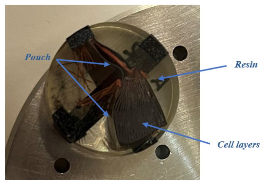
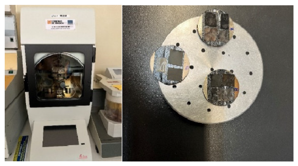
In this section, the transversal-section investigation of the cells will be carried out, which will allow obtaining information about the structure and manufacture of the cells, and the thickness measurement of each of the layers of the cell will be carried out.
Figure 46.
Preparation of samples from the section of cells to be analyzed under the microscope, embedded in resin, and polished.
Figure 46.
Preparation of samples from the section of cells to be analyzed under the microscope, embedded in resin, and polished.
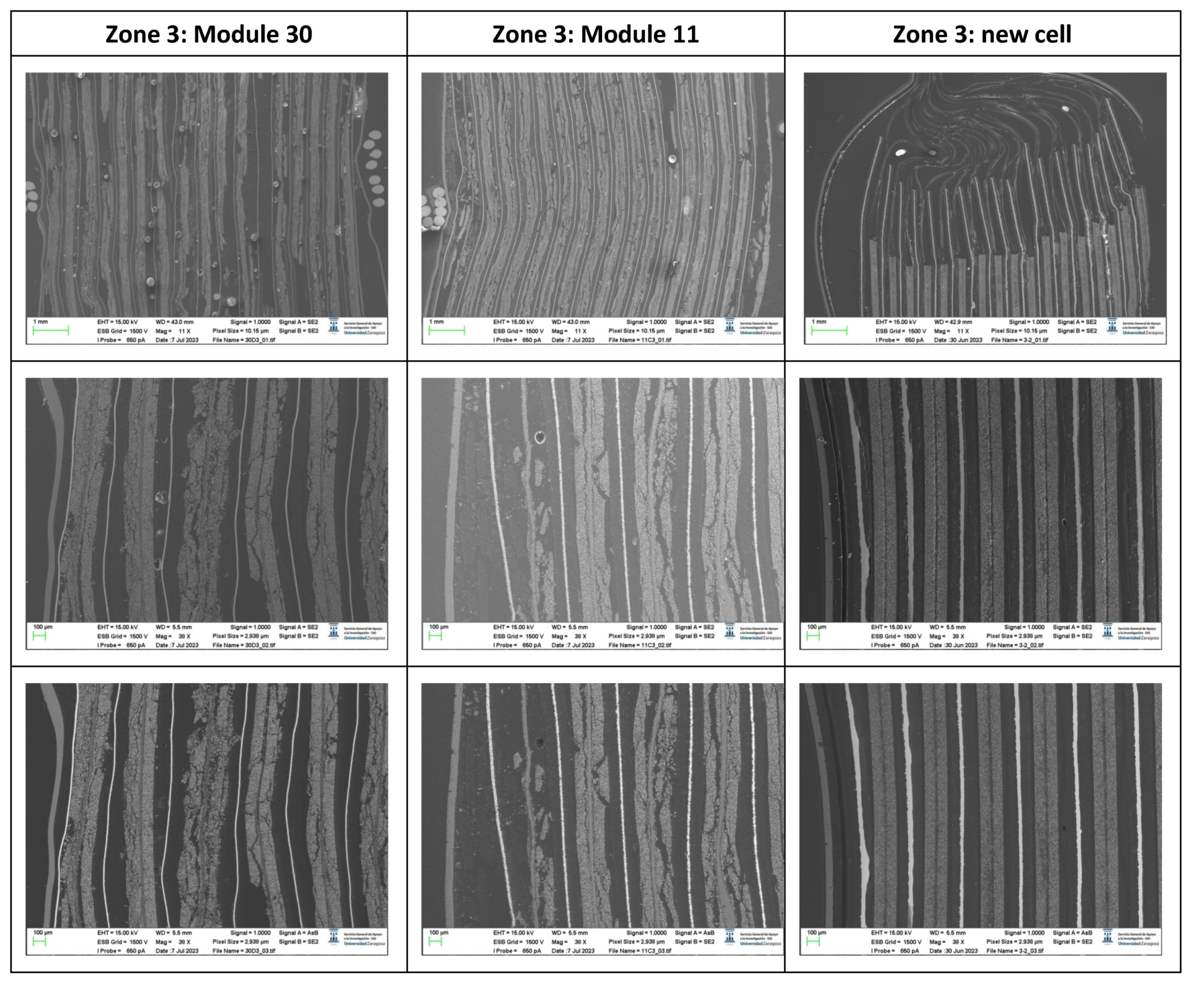
The stacking of the different layers of the cell will be analyzed in transversal-section, which will allow to identify interesting manufacturing details of the pouch cells. First, the sample taken from zone 3 is analyzed, the central area on the opposite side to the side where the battery tabs of the cell are.
It is observed that all the separating membranes are welded to the bag at the sealing point near the edge. Regarding the mechanical behavior of the cell and possible failure of it, this fact indicates that the separator could experience high tensile strain if a mechanical force acted on the battery near this axis and mechanical rupture of the separator membrane could occur. This would cause the battery electrodes to come into contact, which is the prerequisite for experiencing an electrical failure and thermal runaway. It is observed that near the edge of the battery the distances between layers are smaller due to the hot-soldered area of the bag. The lack of layers on this section of the battery ensures that no short circuits will occur, even if some of the battery layers were to get too close to each other.
Another purpose of an anode layer that is longer than the cathode is to increase the rigidity of the battery near the edge, which smooths the distribution of charge in the event of charging at the edge. The investigated cell contained 18 anodic layers, 17 cathode layers, and 34 separator sheets. The electrodes on both sides of the battery were anodes. This observation suggests that the active material deposited on the outer face of the last copper foil remained electrochemically inactive and did not participate in the charge transfer or energy storage process.
In lithium-ion batteries, a layer of aluminum oxide (Al2O3) is usually deposited on the separator membrane to improve its thermal resistance, also improving its thermal properties.
Figure 47.
Images of the section of the pouch cell in zone 3 (central area of the opposite side to the one where the battery tabs of the cell are located).
Figure 47.
Images of the section of the pouch cell in zone 3 (central area of the opposite side to the one where the battery tabs of the cell are located).
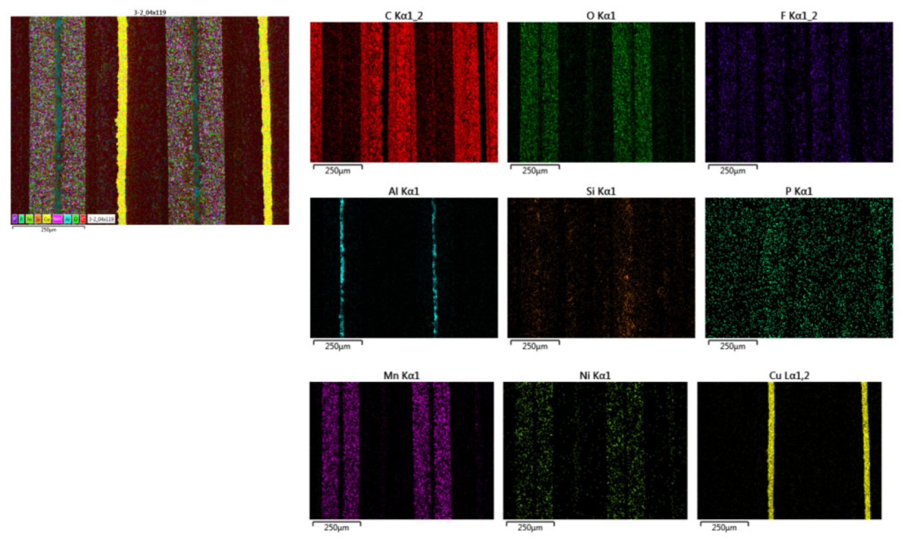
If the morphology is analyzed, it can be concluded that the outer area of zone three is more damaged in the case of module 11, while in the case of module 30 the central area is more damaged. It is also observed that the thickness of the copper collector decreases in case of thermal runaway, and it is observed to be narrower for module 30. To know the chemical composition of zone 3 in the original cell, a map of the distribution of elements was made. The copper collector (yellow) and the aluminum collector (blue) are identified. The coating of the anode is also observed, which is made of graphite (carbon, red color) and the coating of the cathode (composed of oxygen, manganese, nickel). Electrolyte fluoride is also observed.
Figure 48.
Distribution of the elements of a new pouch cell in zone 3 (central area of the opposite side to the one where the battery tabs of the cell are located).
Figure 48.
Distribution of the elements of a new pouch cell in zone 3 (central area of the opposite side to the one where the battery tabs of the cell are located).
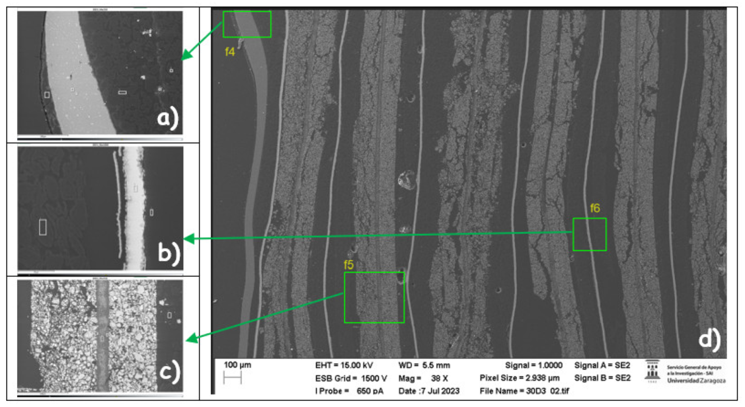
After that, the chemical composition of zone 3 was analyzed for the case of the cell of the burned module 30.
Figure 49.
Chemical composition of each of the layers of the pouch cell of module 30 in zone 3 (central zone of the opposite side to that of the battery tabs of the cell).
Figure 49.
Chemical composition of each of the layers of the pouch cell of module 30 in zone 3 (central zone of the opposite side to that of the battery tabs of the cell).
Figure 49.a identifies the pouch of the pouch cell which is made of aluminum (zones 2 and 3). In zone 5 there is carbon that may be graphite from the anode coating.
Figure 49.c identifies the cathode (manganese nickel oxide) and there are also carbon particles. Around the aluminum manifold, alumina (Al
2O
3) has been deposited on the separator in the cathode area. Alumina (aluminum oxide) has been deposited. In
Figure 49.b the anode area has been detected, graphite (carbon) coating, then there is a layer with cooper and oxygen and the anode collector shell.
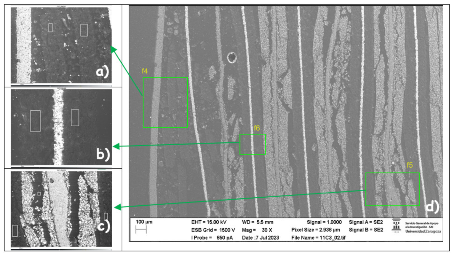
Moreover, the chemical composition of zone 3 is analyzed in the case of the cell of the burning module 11.
Figure 50.
Chemical composition of each of the layers of the pouch cell of module 30 in zone 3 (central zone of the opposite side to that of the battery tabs of the cell).
Figure 50.
Chemical composition of each of the layers of the pouch cell of module 30 in zone 3 (central zone of the opposite side to that of the battery tabs of the cell).
Figure 50.a identifies the pouch of the pouch cell which is made of aluminum (zone 1 and 2), it appears more damaged than the bag of module 30. In zones 6 and 8 there is compound of carbon and oxygen with some fluorine from the electrolyte and in zone 7 there is a compound of carbon and oxygen with aluminum from the cathode collector.
Figure 50.c identifies the cathode (manganese oxide) and there are also carbon particles. In this case, aluminum is not observed. In
Figure 50.b the anode zone has been detected, then there is a copper layer, copper collector and then there are silicon particles and then a graphite coating layer is detected. The silicon particles could be due to traces of a sealant material.
The sample obtained in zone 1 (anode battery tabs) is analyzed below:
Figure 51.
Images of the pouch cell section in zone one (anode zone) of the cell.
Figure 51.
Images of the pouch cell section in zone one (anode zone) of the cell.
If the morphology is analyzed, it can be observed that in zone one module 30 is more damaged than module 11. It is also observed that the thickness of the copper collector decreases in the case of thermal runaway, and it is observed to be narrower in the case of module 30.
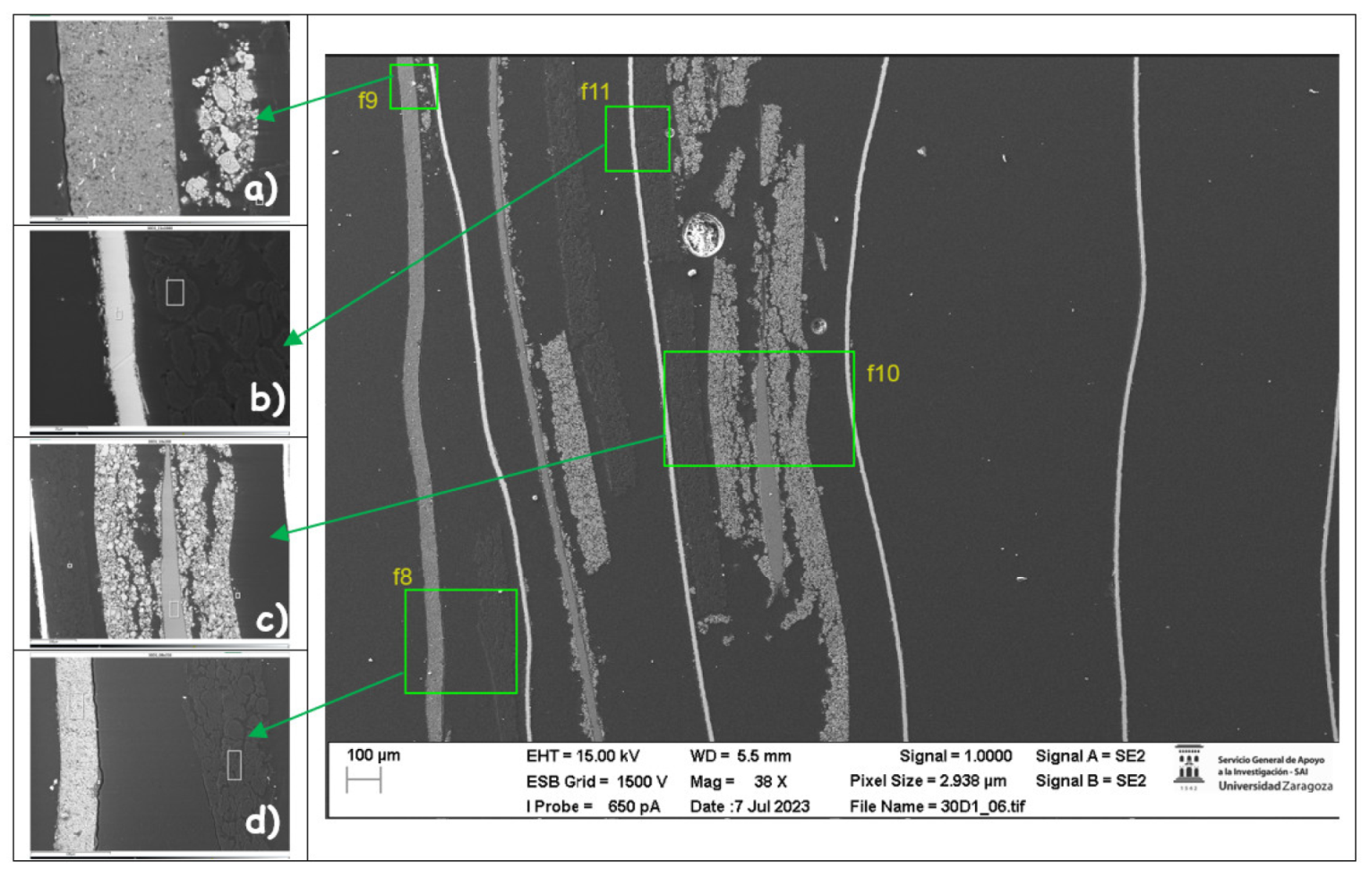
Subsequently, the chemical composition of zone 1 is analyzed in the case of the cell of module 30 that caught fire.
Figure 52.
Chemical composition of each of the layers of the pouch cell of module 30 in zone 1 (anode zone).
Figure 52.
Chemical composition of each of the layers of the pouch cell of module 30 in zone 1 (anode zone).
Figure 52a identifies a compound of nickel and oxygen in zone 1 with traces of carbon and manganese, a compound of manganese and oxygen in zone 2 and a compound of carbon and oxygen in zone 3.
Figure 52.b identifies a compound of copper, carbon, and oxygen in zone 1 and zone 3, copper in zone 2 which is the anode collector, and a compound of carbon and oxygen in zone 4.
Figure 52.c identifies carbon, anode coating in zone 1, a compound of manganese, oxygen, and carbon in zone 2, cathode coating in zone 2, cathode aluminum collector in zone 3, fluorine from the electrolyte in zone 4, and a compound of aluminum and oxygen in zone 5. Finally,
Figure 52.d identifies a compound of copper, carbon, and oxygen in zones 1 and 3, copper in zone 2 which is the copper collector of the anode, and a compound of carbon and oxygen in zone 4.
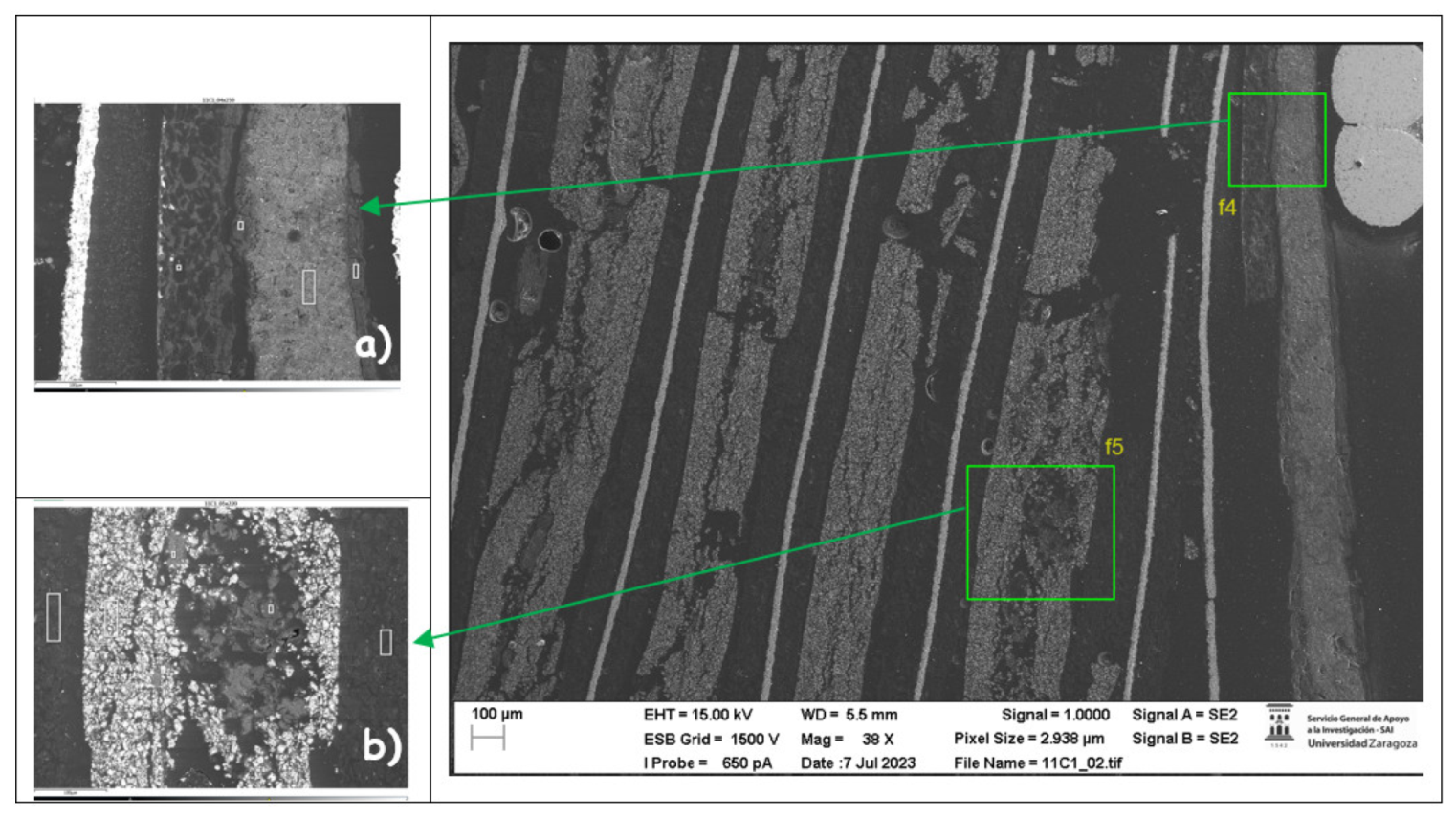
Next, the chemical composition of zone 1 is analyzed in the case of the cell of the burned module 11.
Figure 53.
Chemical composition of each of the layers of the pouch cell of module 11 in zone 1 (anode zone).
Figure 53.
Chemical composition of each of the layers of the pouch cell of module 11 in zone 1 (anode zone).
Figure 53.a identifies a compound of carbon, oxygen, and aluminum in zone 1 and 2, aluminum and carbon in zone 3 which is the pouch bag, in zone 4 carbon, oxygen and aluminum and some copper. And in zone 5 carbon which is the coating of the anode. In
Figure 53. B a compound of carbon and oxygen is identified in zone 1, 4 and 5, in zone 4 there is also some aluminum. In zone 2, there is a compound of manganese, carbon and oxygen, cathode coating and in the center, zone 3, there is a compound of aluminum and oxygen from the aluminum collector that has melted down and disappeared.
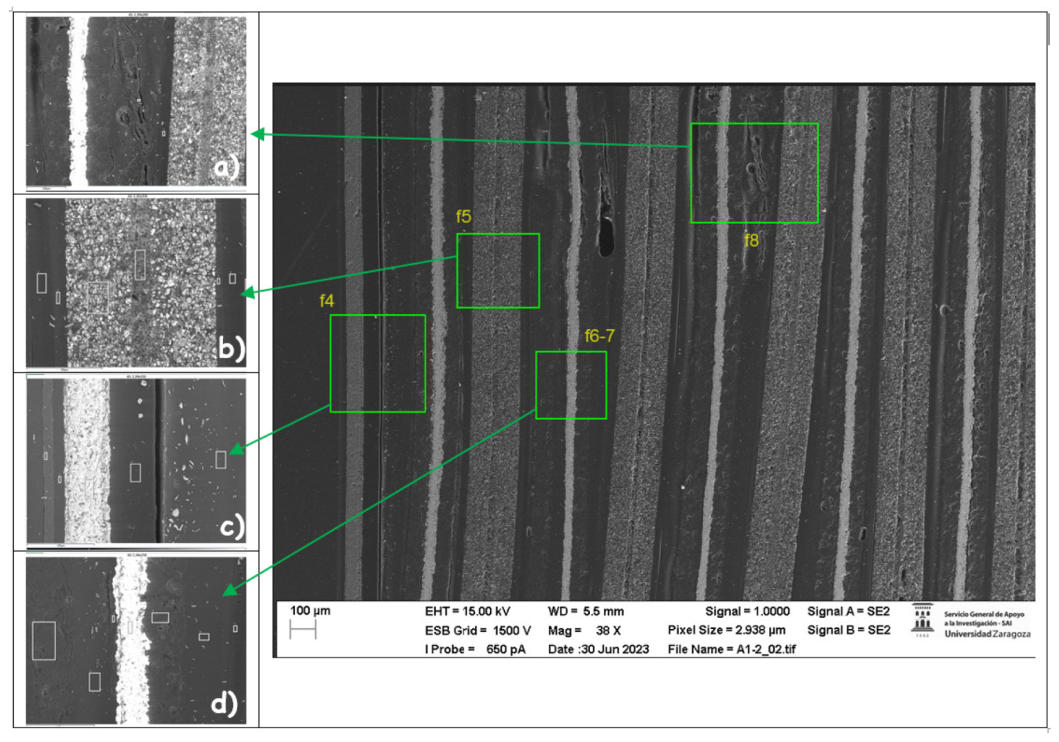
The chemical composition of zone 1 is then analyzed in the case of the new cell:
Figure 54.
Chemical composition of each of the layers of the new pouch cell in zone 1 (anode zone).
Figure 54.
Chemical composition of each of the layers of the new pouch cell in zone 1 (anode zone).
Figure 54.a identifies a compound of carbon and oxygen in the three zones analyzed,
Figure 54.b identifies a compound of carbon and oxygen in zones 1, 2, 5 and 6 and a compound of manganese, carbon, oxygen, and fluoride in zone 3, and carbon and aluminum in zone 4.
Figure 54.c identifies the bag that is aluminum in zone 3, coated on both sides by a compound of carbon and oxygen.
Figure 54.d identifies the copper collector of the anode in zone 4, which is coated by a compound of carbon and oxygen.
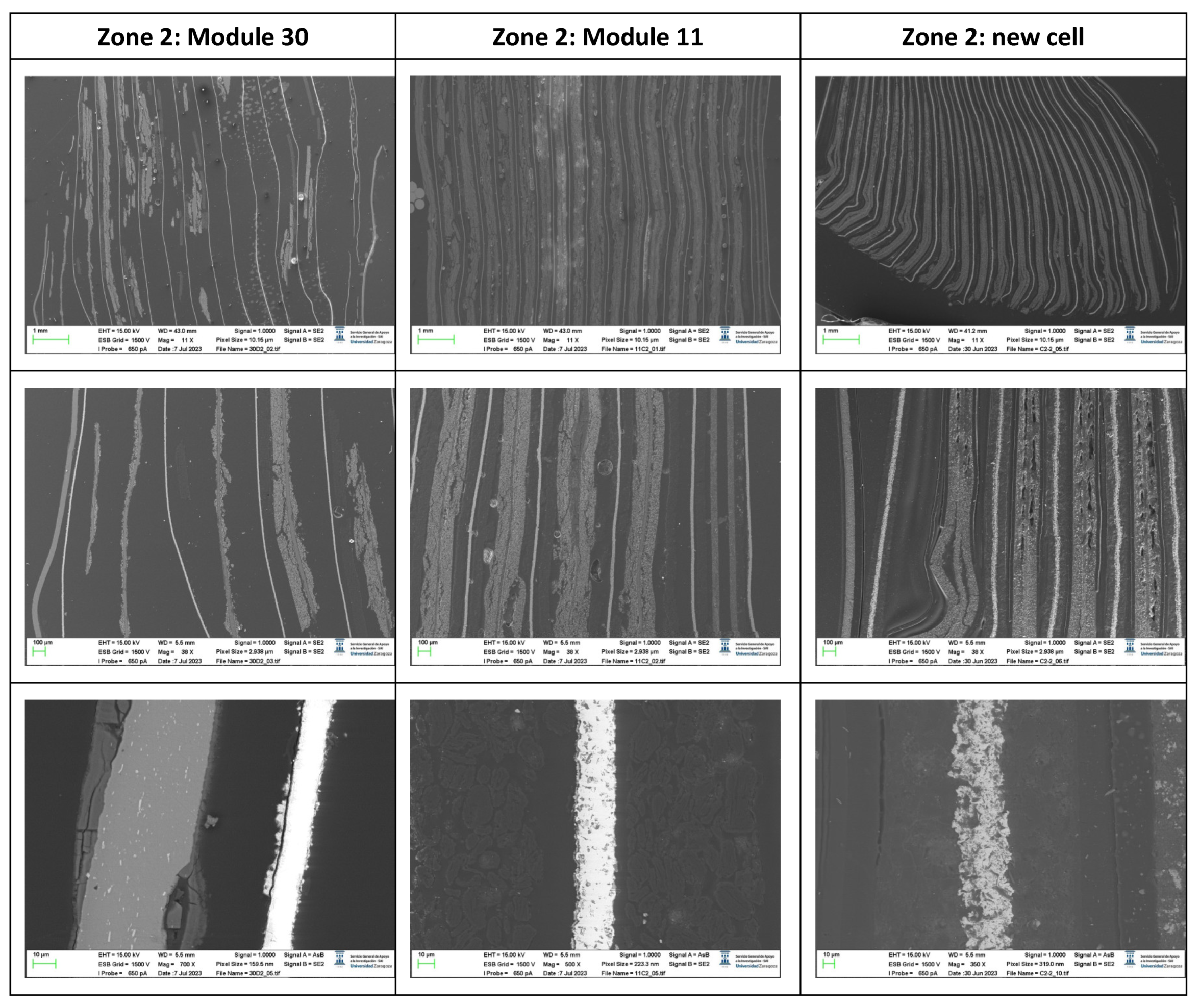
The sample obtained in zone 2 (cathode battery tabs) is analyzed below:
Figure 55.
Images of the pouch cell section in zone two (cathode zone) of the cell.
Figure 55.
Images of the pouch cell section in zone two (cathode zone) of the cell.
If the morphology is analyzed, in zone 2 module 30 is more damaged than module 11. It is also observed that the thickness of the copper collector decreases in the case of thermal runaway and is observed to be narrower in the case of module 30.
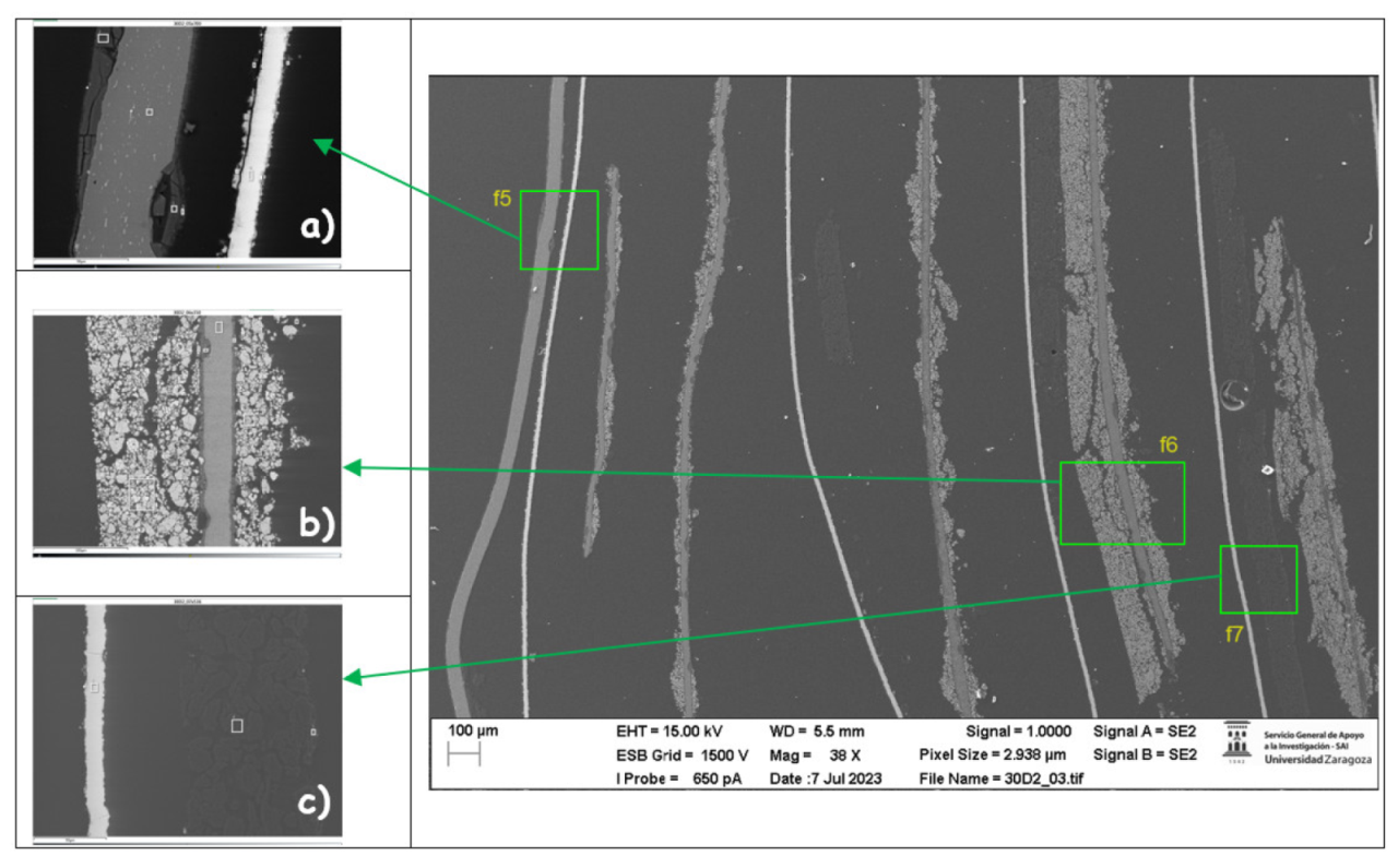
Next, the chemical composition of zone 2 is analyzed in the case of the cell of the burning module 30.
Figure 56.
Chemical composition of each of the layers of the module 30 pouch cell in zone 2 (cathode zone).
Figure 56.
Chemical composition of each of the layers of the module 30 pouch cell in zone 2 (cathode zone).
Figure 56.a identifies a layer of a compound of carbon and oxygen (zone 1), a layer of a compound of aluminum and oxygen (zone 2) and the aluminum pouch (zone 3), a layer of an aluminum and oxygen compound (zone 5) and a layer of a carbon and oxygen compound (zone 6), anode copper collector (zone 8), and a layer of a compound of cooper and oxygen (zone 7 and zone 9).
Figure 56.b identifies a compound of manganese, carbon, and oxygen in zone 1 and 5, a layer of an aluminum and oxygen compound in zones 2 and 4, and aluminum and carbon in zone 3, the cathode collector.
Figure 56.c identifies a compound of copper, carbon, and oxygen in zones 1 and 3 and copper and carbon in zone 2, which is the collector and anode.
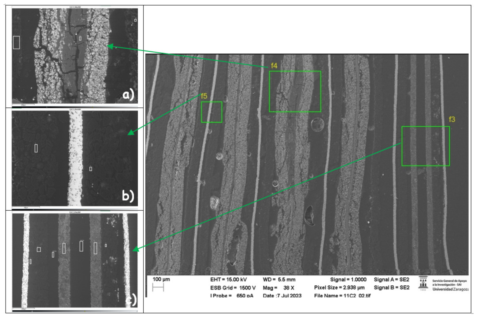
Next, the chemical composition of zone 2 is analyzed in the case of the cell of the burning module 11.
Figure 57.
Chemical composition of each of the layers of the module 11 pouch cell in zone 2 (cathode zone).
Figure 57.
Chemical composition of each of the layers of the module 11 pouch cell in zone 2 (cathode zone).
Figure 57.a shows the cracking of the collector and cathode coating, identifying a compound of aluminum and oxygen (zone 2 and zone 4) within a layer of manganese, carbon, nickel, and oxygen (zone 3).
Figure 57.b identifies a layer of carbon (zone 1 and zone 7), a layer with a compound of copper, carbon, and oxygen (zone 2, 3), a zone with a compound of copper and oxygen, that is the collector of the anode, and a zone that has silicon (zone 5 and zone 6).
Figure 57.c shows a copper zone (zone 1 and zone 8) with two collectors, zones 4 and 5 are carbon and aluminum, resin layers are also identified and in zone 7 carbon with traces of silicon and copper is observed. The silicon particles could be due to traces of a sealant material.
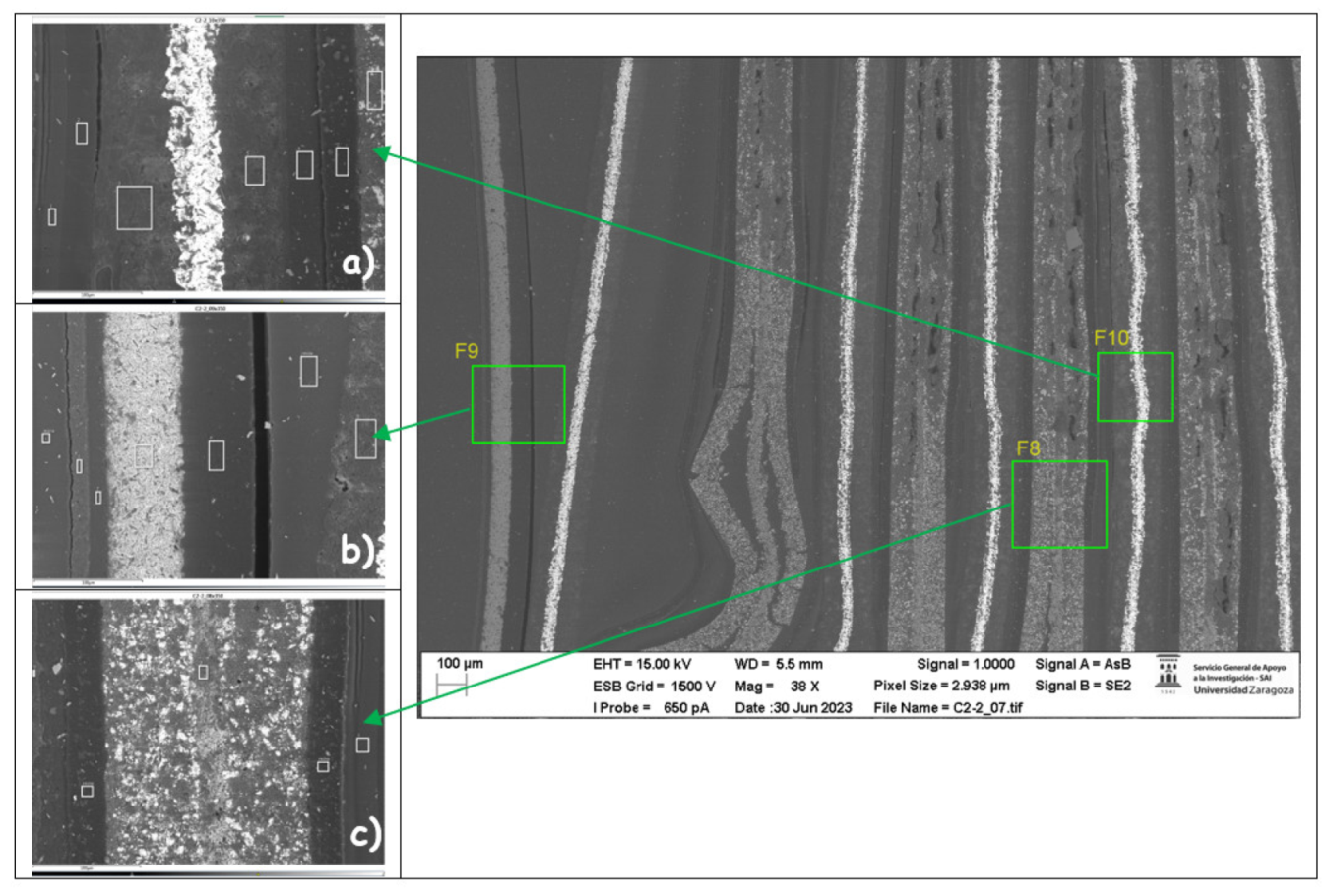
The chemical composition of zone 2 is then analyzed in the case of the new cell.
Figure 58.
Chemical composition of each of the layers of the new pouch cell in zone 2 (cathode zone).
Figure 58.
Chemical composition of each of the layers of the new pouch cell in zone 2 (cathode zone).
Figure 58.a shows the copper collector with carbon and some silicon (zone 4), a layer of a compound of carbon and oxygen on either side of the collector that comes from the graphite in the anode.
Figure 58.b shows the aluminum pouch with carbon and a compound of carbon and oxygen layers.
Figure 58.c shows layers of a carbon and oxygen compound, zone 3 shows aluminum and carbon, zone 4 shows a compound of manganese and oxygen, and zone 5 shows carbon and silicon. As stated above the silicon particles could be due to traces of a sealant material.
